EP1914839A2 - Installation switching device - Google Patents
Installation switching device Download PDFInfo
- Publication number
- EP1914839A2 EP1914839A2 EP07019448A EP07019448A EP1914839A2 EP 1914839 A2 EP1914839 A2 EP 1914839A2 EP 07019448 A EP07019448 A EP 07019448A EP 07019448 A EP07019448 A EP 07019448A EP 1914839 A2 EP1914839 A2 EP 1914839A2
- Authority
- EP
- European Patent Office
- Prior art keywords
- terminal
- switching device
- connection
- clamping
- cover
- Prior art date
- Legal status (The legal status is an assumption and is not a legal conclusion. Google has not performed a legal analysis and makes no representation as to the accuracy of the status listed.)
- Granted
Links
- 238000009434 installation Methods 0.000 title claims description 39
- 239000004020 conductor Substances 0.000 claims description 91
- 125000006850 spacer group Chemical group 0.000 claims description 23
- 238000003780 insertion Methods 0.000 claims description 20
- 230000037431 insertion Effects 0.000 claims description 20
- IHQKEDIOMGYHEB-UHFFFAOYSA-M sodium dimethylarsinate Chemical class [Na+].C[As](C)([O-])=O IHQKEDIOMGYHEB-UHFFFAOYSA-M 0.000 claims description 16
- 239000000463 material Substances 0.000 claims description 10
- 238000005452 bending Methods 0.000 claims description 9
- 230000008878 coupling Effects 0.000 claims description 7
- 238000010168 coupling process Methods 0.000 claims description 7
- 238000005859 coupling reaction Methods 0.000 claims description 7
- 238000012360 testing method Methods 0.000 claims description 7
- 238000001746 injection moulding Methods 0.000 claims description 6
- 230000006835 compression Effects 0.000 claims description 2
- 238000007906 compression Methods 0.000 claims description 2
- 230000008901 benefit Effects 0.000 description 8
- 238000003825 pressing Methods 0.000 description 5
- 238000013461 design Methods 0.000 description 4
- 238000000034 method Methods 0.000 description 4
- 238000002347 injection Methods 0.000 description 3
- 239000007924 injection Substances 0.000 description 3
- 238000004519 manufacturing process Methods 0.000 description 3
- 230000007704 transition Effects 0.000 description 3
- 230000009471 action Effects 0.000 description 2
- 230000001154 acute effect Effects 0.000 description 2
- 230000000712 assembly Effects 0.000 description 2
- 238000000429 assembly Methods 0.000 description 2
- 230000005540 biological transmission Effects 0.000 description 2
- 230000008859 change Effects 0.000 description 2
- 238000010276 construction Methods 0.000 description 2
- 238000011161 development Methods 0.000 description 2
- 238000010292 electrical insulation Methods 0.000 description 2
- 230000007935 neutral effect Effects 0.000 description 2
- 230000008569 process Effects 0.000 description 2
- 230000000087 stabilizing effect Effects 0.000 description 2
- 239000013589 supplement Substances 0.000 description 2
- 238000009411 base construction Methods 0.000 description 1
- 238000005520 cutting process Methods 0.000 description 1
- 238000009826 distribution Methods 0.000 description 1
- 230000002349 favourable effect Effects 0.000 description 1
- 238000009413 insulation Methods 0.000 description 1
- 239000002075 main ingredient Substances 0.000 description 1
- 239000002991 molded plastic Substances 0.000 description 1
- 239000004033 plastic Substances 0.000 description 1
- 229920003023 plastic Polymers 0.000 description 1
- 239000000523 sample Substances 0.000 description 1
- 238000000926 separation method Methods 0.000 description 1
- 239000007779 soft material Substances 0.000 description 1
- 239000007787 solid Substances 0.000 description 1
- 210000002023 somite Anatomy 0.000 description 1
Images


Classifications
-
- H—ELECTRICITY
- H01—ELECTRIC ELEMENTS
- H01R—ELECTRICALLY-CONDUCTIVE CONNECTIONS; STRUCTURAL ASSOCIATIONS OF A PLURALITY OF MUTUALLY-INSULATED ELECTRICAL CONNECTING ELEMENTS; COUPLING DEVICES; CURRENT COLLECTORS
- H01R4/00—Electrically-conductive connections between two or more conductive members in direct contact, i.e. touching one another; Means for effecting or maintaining such contact; Electrically-conductive connections having two or more spaced connecting locations for conductors and using contact members penetrating insulation
- H01R4/28—Clamped connections, spring connections
- H01R4/48—Clamped connections, spring connections utilising a spring, clip, or other resilient member
- H01R4/4809—Clamped connections, spring connections utilising a spring, clip, or other resilient member using a leaf spring to bias the conductor toward the busbar
- H01R4/4828—Spring-activating arrangements mounted on or integrally formed with the spring housing
- H01R4/48365—Spring-activating arrangements mounted on or integrally formed with the spring housing with integral release means
Definitions
- the invention relates to an installation switching device with a housing and with two screwless terminal connections, each with at least one clamping spring for connecting connecting conductors, which is fixed in position in a terminal connection space of the housing, according to the preamble of claim 1.
- a generic installation switching device comprises within its housing at least one contact point with at least one fixed and one movable contact piece, via which a current leading from an input to an output terminal current path can be opened and closed.
- the contact point is generally operated by a rear derailleur with Verklinkungsstelle.
- a generic service switching device may further comprise tripping devices, for example a thermal release or a magnetic quick release, which act on the contact point or the rear derailleur when a short circuit or fault current occurs in the current path, so that the contact point is opened.
- screw-type terminal connections are used in addition to screw terminals in generic service switching devices.
- clamping elements can thereby plug terminals or spring terminals for Use come. In principle, these can greatly simplify the connection of connecting conductors, but today known installation switching devices with screwless terminal connections are subject to disadvantages.
- the EP 1 213 791 B1 shows an installation switching device with two superimposed and partially transversely shifted fasteners spring-type terminal. The actuation of the terminal element is only possible with an external tool.
- each terminal connection space to the housing sides and the front side open, and the two terminal connections are transverse to the broad side next to each other and in height above the mounting side against each other, and each of the two terminal terminals is covered by a terminal cover member pivotally connected to the housing.
- Each terminal cover part has a connection surface with a number of connection openings corresponding to the number of connection conductors to be connected, and guide means for the connection conductors formed on each connection opening.
- each terminal cover part has two side surfaces which, when attached Cover the terminal cover part of the terminal connection assigned to it laterally in the direction of the broad sides.
- spring actuation means are formed on the terminal cover and formed so that they act upon opening the cover against the clamping spring opening.
- the guide means are tube-like, an insertion channel forming hollow body, which also serve as a spring actuating means for the clamping spring.
- Each terminal connection of a service switching device comprises very few components, namely essentially only the clamping spring, a busbar with a clamping edge against which the clamping spring clamps the connecting conductor to be connected, and the terminal cover.
- An inventive installation switching device comprises two such terminal connections, which are arranged side by side on a connection side of the device. It is therefore very easy and inexpensive to manufacture.
- the two terminal connections are also offset in height above the mounting side against each other and thus offset. In this way, the creepage and clearance between the two terminal connections are lengthened, further securing the electrical insulation between the two terminal connections.
- An installation switching device has the overall advantage that two terminal connections are mounted on one connection side and in a terminal connection space in a simple manner and from the outside very convenient accessible side by side, the two terminal terminals are electrically isolated from each other and independently operable without tools. For insertion as well as removal of fixed and flexible terminal connection leads into or out of the terminal connection, no external tool is required.
- the terminal connections are easy to set up with just a few prefabricated components
- each terminal cover is resiliently acted upon by the associated clamping spring against the insertion direction of the external connection conductor and pressed against this clamping spring.
- the terminal cover part can be resiliently acted upon by the clamping spring assigned to it against a projection of the housing wall serving as a stop.
- the terminal cover is held by the resilient application of the associated clamping spring in a defined starting position. The starting position is the closed position of the clamping spring.
- the terminal cover can be made particularly simple and can be produced for example as a cost-effective injection molded part.
- the terminal cover part has an externally accessible, manually operable pressure surface.
- a further advantageous variant of the invention is characterized in that the terminal connection space between the two terminal connections comprises an insulating plate running parallel to the broad sides.
- the terminal connection space between the two terminal connections comprises an insulating plate running parallel to the broad sides.
- the terminal cover part can have a test opening for electrical contacting of the terminal connection.
- a further advantageous variant of the invention is characterized in that an adjustment opening is made in the vicinity of a terminal cover part in the housing wall. This makes it possible to intervene during manufacture or in the installed state of the finished mounted switching device with a tool inside the switching device to access an arranged there in the vicinity of the adjustment opening adjustment means.
- the terminal surface of the terminal cover with respect to the front of the housing and the guide means relative to the pad provides a possible embodiment of the invention that the terminal surface of the terminal cover is approximately parallel to the rear front side and the guide means are inclined relative to the terminal surface of the terminal cover.
- the angle of inclination for the guide means is selected, for example, according to the fact that the connection conductors remain easily accessible when mounting a service switching device according to the invention, for example in a distribution box, and the connection conductors are not bent too much towards the top.
- a further advantageous embodiment provides in this respect that the terminal surface of the terminal cover part inclined relative to the rear front side and the guide channels extend approximately perpendicular to the connection surface.
- the inclination angle at which the leads are inserted relative to the spring clip is determined in this embodiment by the angle of inclination of the guide channels.
- connection surface of the terminal cover opposite the rear front side, and the guide channels are inclined relative to the connection surface.
- the terminal cover having an engagement opening for an operating tool. Through this engagement opening can then be spent with the actuating tool, such as a screwdriver, the clamping spring in its open position.
- each terminal cover pivotally coupled a closure member which covers the terminal connection space on the front side in cooperation with a housing-fixed front end, wherein upon actuation of each terminal cover the closure member with the housing-side front end at least partially overlapped.
- the respective closure part and the housing-fixed part of the front side together form the front side.
- the respective closure part thus acts as a supplement to the housing-fixed part as klemmenabdeckteil workedes part of the front.
- the closure part is plate-shaped. It may advantageously be made in the same injection molding process as the terminal cover.
- a hinge for example a film hinge.
- a film hinge can be produced very inexpensively by injection molding.
- Another very advantageous embodiment of the invention is characterized in that the respective closure part is guided in each case displaceably parallel to the front side via laterally projecting guide pins in a housing-fixed, slide-like guide.
- the respective closure part is then overlapped and displaceably guided with the respectively associated housing-side part of the front side. It can be pivoted and moved when pressing the respective terminal cover behind the respective associated housing-side part of the rear front.
- a tight covering of the terminal receiving space is ensured to the front side with simultaneous movement of the terminal cover and mechanical stability of the rear front.
- a further very advantageous development of the invention is characterized in that the respective terminal cover part carries a spacer surface following the connection surface, which forms the terminal cover-side closure of the terminal receiving space in the region of the respective narrow side, the closure part being pivotably coupled to the end of the spacer surface facing the front side is.
- the spacer surface is designed to be stiff.
- a power transmission to the spring of the terminal is also possible by pressing the terminal cover over the spacer surface.
- the pressure surface of the terminal cover is due to the location of the terminal very close to the mounting side of the switching device in the installed position of the switching device, for example, in an installation distributor, by an operator is difficult to access.
- the distance surface can thus be used in a region which is not covered by a connecting conductor, as a second pressure surface for actuating the spring.
- the spacer surface carries an engagement opening for an actuating tool.
- the terminal can thus be operated via the terminal cover either manually or by means of a tool.
- the respective closure part is at least in the region of the coupling with the first part body of a material that has different mechanical properties than the first part body of the terminal cover.
- the closure part covers the terminal connection space on the front side in cooperation with a housing-fixed front side end, wherein upon actuation of the terminal cover part, the closure part at least partially overlaps the housing-fixed front side end.
- the respective closure part and the housing-fixed part of the front side together form the front side.
- the respective closure part thus acts as a supplement to the housing-fixed part as klemmenabdeckteil workedes part of the front.
- the hinge and the respective closure part in the region of the hinge consists of a material which has different mechanical properties than the first part body of the terminal cover part.
- the respective closure part at least in the region of the coupling with the first part body of the respective terminal cover part, consists of a material with different mechanical properties than the latter, the resilient properties of the respective closure part and its coupling to the respectively first part body can be independent of those of the respective first part Part body of the terminal cover part set and optimized for the intended use. This is particularly advantageous if other, sometimes even opposite, mechanical requirements are placed on the respective first part body of the terminal cover part than on the closure part.
- the first sub-body of the respective terminal cover has a high rigidity, so that the force can be transmitted to the opening of the respective clamping spring without deformation of the respective terminal cover.
- the respective closure part should be flexible, but at least flexibly coupled to the first part of the body of the terminal cover so that it can slide to save space during the pivoting of the terminal cover in the backdrop-like guides behind the housing-side front end.
- the closure part should be as parallel as possible to the housing-fixed front end.
- the angle between the first sub-body of the terminal cover and the housing-fixed front end changes during pivoting of the terminal cover. Therefore, a mobility of the closure part relative to the first part body of the terminal cover part is required at the coupling point, which can only be achieved by a flexibility of the material at this point.
- the spacer surface is designed stiff, and the closure part is at least in the region of the coupling with the spacer surface made of a soft material, which is softer than the spacer surface executed.
- a single component, the respective terminal cover has different material properties in some areas. Due to the rigid part of a transmission of force to the respective spring of the terminal is also possible by pressing the terminal cover over the spacer surface.
- the closure part, the second part can nevertheless turn easily and move parallel to the front panels and behind them.
- the terminal cover part is produced with the closure part coupled thereto in a two-component injection molding process.
- materials with different mechanical properties so for example hard and soft plastics, are joined together in injection molding.
- each terminal connection of an installation switching device comprises a compression spring acting on the conductor end clamping spring for clamping the conductor end to an abutment
- the clamping connection comprises a busbar with a terminal end and an adjoining discharge area.
- the busbar has a window-like recess with a supporting edge and a clamping edge opposite the supporting edge at the transition of the connection end into the diverting region.
- the clamping spring also has a support leg, with which it is supported on the support edge of the busbar. At the support leg includes a curved piece and a clamping leg, so that the conductor end between the clamping leg and the clamping edge is clamped as an abutment. The conductor end can be inserted from the side of the elbow piece into the window-like recess.
- the invention connects to the respective elbow a first part-clamping leg, which merges at a bending edge in a bent from the respective first part-clamping leg second part-clamping legs, so that the respective first and the second part-clamping legs a occupy obtuse angle with each other, the opening points in the insertion direction of the connecting conductor.
- the obtuse angle between the respective first and the respective second partial clamping legs offers the advantage that the point of application can be placed in the vicinity of the spring actuating means in the vicinity of the bending edges.
- the contact point of the spring actuating means may have a greater distance to the pivot point of the clamping leg on the elbow without the thereby achievable maximum terminal opening is smaller, and without the spring actuating means would be a connection conductor with a large cross section in the way.
- a greater distance between the contact point and the pivot point means a more favorable lever ratio and thus a lower actuation force for the user.
- a preferred embodiment is characterized in that the busbar has approximately a U-shape, wherein the terminal end forms the one U-leg, and the diverting region is formed by the transverse web and the other U-leg. It can be provided at the free end of the other U-leg upstand for attaching further conductors that lead into the interior of the service switching device.
- a discharge bar at the free end of the other U-leg and a discharge bar may be formed.
- the discharge bar can run approximately perpendicular to the other U-leg, and the side of the connection end opposite the clamping edge can be supported on the discharge bar.
- Another advantage of a service switching device is that the dissipation region of the busbar can be used for electrical contacting during the calibration of the bimetallic strip.
- the contact point for the calibration of the bimetallic strip is located at another location, outside the access area of the terminal connection, and is not accessible via the terminal connection. Since the calibration of the bimetallic strip can only take place in the fully assembled state, in the case of known service switching devices following the calibration, the separate access openings to the calibration contacts must be covered by additional cover parts.
- An inventive installation switching device can be completely assembled, except for the terminal cover parts. Now - by means of electrical contacting through the opening of the terminal terminal - the calibration of the bimetallic strip is made by the Ableit Scheme the busbar is used as a calibration contact. After calibration, the terminal cover is placed, and thus completed the installation switching device. A separate cover for the calibration opening is no longer required.
- the terminal connections of a service switching device according to the invention are designed so that they have only a small electrical resistance even with very narrow outer dimensions. This is achieved in that the bus bar in the discharge region between the clamping edge and the point at which another conductor is fixed, which leads into the interior of the service switching device, has a uniform width. This makes it possible to build installation switching devices according to the invention also in half standard module width.
- a division unit a is defined for the installation width of service switching devices.
- An installation switching device with a half standard module width thus has a mounting width of 9 mm.
- the busbar has only a single window-like recess for receiving a plurality of connection conductors.
- the individual connection conductors which are accommodated in the one recess of the busbar, are held apart by the connection openings and the guide means connected to them. For an individual insertion and removal of multiple connection conductors in only a single recess is possible without the individual connection conductors affect each other.
- the invention makes it possible to use two terminal connections next to one another in an installation switching device of a standard module width, which are electrically isolated from one another and do not have to overlap. As a result, electrical crosstalk between the two adjacent terminal connections is reliably avoided.
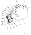
- FIGS. 1 to 5 An installation switchgear 1 according to the invention, see FIG. 1, has an insulating housing 3 formed from two housing parts 2, 2 'joined along a parting line 2a with a front front 4, rear front sides 5, 5', a fastening or connection side 6, front narrow sides 7, 7 ', which connect the front front side 4 with the rear front sides 5,5', rear narrow sides 8, 8 ', and two broad sides 9, of which in the view of Figure 1, only one is shown.
- a conventional screw terminal accessible by a terminal opening 11 for connecting connecting conductors is mounted in a terminal connection space provided inside the housing 3.
- a terminal connection space 18 is provided, which is open to the housing broad sides 9, to the rear narrow side 8 and to the rear front side 5.
- the terminal connection space 18 there are two terminal connections 10, 10 'which are transverse to the broad side 9 next to each other, and are shifted in height above the attachment side 6 against each other. Seen from the attachment side 6, therefore, a first terminal connection 10 lies above a second terminal connection 10 '.
- Each of the two terminal connections 10, 10 ' is fixed in position in the terminal connection space 18 and accessible for the connection of connection conductors 14 (see FIG. 3). Due to the openness of the terminal connection space on four sides, an increased flexibility for the connection direction of the connection conductor 14 is given.
- Each of the two terminal connections 10, 10 ' is covered by a terminal cover part 22, 22' assigned to it. This serves on the one hand to protect against contact of the current-carrying terminal connections, on the other hand - as will be shown below - it ensures a tool-free operation of the terminal connections.
- the cover of the terminal connection space 18 pointing towards the interior of the device is formed by a section 8a of the housing wall.
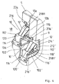
- the terminal cover 22, 22 ' has substantially the shape of a box open on two sides (see also Figure 2, in which as a section of Figure 1, only the upper terminal terminal 10 is shown). Two sides of this box are formed by two opposing cover plates on which laterally two side surfaces 29, 29 'are formed, which cover the terminal connection 10,10' laterally in the direction of broadsides 9 out.
- the first cover plate covers the associated terminal connection 10 or 10 'toward the rear front side 5 and has a connection surface 24 or 24', each with two connection openings 26 and 26 ', wherein a connection conductor can be connected through each of the connection openings 26, 26' ,
- the second cover plate covers the associated terminal connection 10 or 10 'toward the rear narrow side 8 and has an externally accessible, manually operable pressure surface 230 or 230'. At the free edge of the second cover plate has a semi-open, tubular cavity with which they are in one connected to the rear narrow side 8 of the housing 3 pivot pin 232 or 232 'is rotatably mounted.
- FIG. 1 shows an inventive installation switching device 1 with the terminal cover parts 22, 22 '
- FIG. 4 shows a view of the terminal connection space 18 with terminal cover parts removed.
- Each of the terminal connections 10 and 10 ' is a so-called plug-in terminal. Its construction will be described with reference to FIG. 3, which shows the terminal connection 10 from FIG. 2, but with the side face 29 of the terminal cover part 22 removed, and with reference to FIG. 4, in which the arrangement of the two terminal connections 10 and 10 'in the terminal connection compartment 18 is shown. be explained.
- the reference numerals without apostrophe refer to the upper terminal terminal 10, the reference numerals with apostrophe refer to the lower terminal terminal 10 '.
- the reference numerals without apostrophe are not mentioned because of the easier readability, however, drawn in the figures. Otherwise, the two terminal connections 10, 10 'are constructed essentially identically.
- the terminal connection 10 comprises a busbar 102 and a clamping spring 12.
- the terminal connection 10 rests on a projection formed in the interior of the housing 3, which is not shown in more detail here, and is there by way of webs and pins, of which only one pin is shown here by way of example 106 is fixed in position in a known manner in the terminal connection space 18.
- the busbar 102 includes a connection end 112 and a subsequent discharge region 114. At the connection end 112, it has a single window-like recess 116 with a support edge 118 and a clamping edge 120 opposite the support edge. The clamping edge 120 is located at the transition of the connection end 112 into the discharge region 114.
- the clamping spring 12 has a support leg 212, with which it is supported on the support edge of the bus bar 102.
- the support can be made so that the support leg 212 has at its free end a raised edge, with which it includes the supporting edge for the purpose of supporting partially.
- a curved piece 214 and thereon a clamping leg 216 connects.
- the conductor end 16 of a connecting conductor 14 is inserted from the side of the elbow 214 ago in the window-like recess 116 and is clamped between the clamping leg 216 and acting as an abutment clamping edge 120.
- the free end of the clamping leg 216 passes through the window-like recess 116th
- the clamping leg 216 of the clamping spring 12 is longitudinally slotted along a slot 218, so that two independently clampable part springs 13a, 13b arise with which two connection conductors can be clamped independently of each other.
- the busbar 102 has approximately a U-shaped basic shape, wherein the terminal end 112 forms the first U-leg, and the discharge region 114 is formed by a transverse web 220 and the second U-leg 222. At the free end of the second U-leg 222 a Aufkantung 224 is attached. At this Aufkantung 224 further connection conductors can be attached, with which the terminal connection 10 is connected to other modules within the switching device housing, such as the trigger assemblies. In particular, the connection conductors can be welded or brazed to this upstand, also a screwing or riveting is possible.
- An illustrated design of the busbar has the advantage that the forces acting on the terminal connection 10 when inserting and releasing the connecting conductor are absorbed by this as a closed system, and thus forces on other elements of the service switching device, such as the housing can be reduced.
- the busbar 102 can be produced cost-effectively and simply and in a wide variety of shapes, for example as a stamped and bent part in very large quantities.
- the terminal cover 22 By pressure on the pressure surface 230, the terminal cover 22 can be pivoted about the free edge of the second cover plate in the direction of the clamping spring 12 out. Falling out of the cover 22 is prevented by serving as a stop projection 234 on the housing wall.
- an insertion channel forming hollow body 28 are attached at the first cover plate of the cover member 22, aligned with the clamping spring 12, at each of the connection openings 26 tubular. These serve as a guide means for the introduced lead 14, and as spring actuation means.
- the cover member 22 is pivoted by pressure on the pressure surface 230 about the pivot pin 232 in the direction of the clamping spring 12, the hollow body 28 press the clamping leg 216 of the clamping spring 12 away from the clamping edge 120 of the bus bar 102, so that between the clamping edge 120th and the clamping leg 216 space for inserting the stripped terminal conductor end 16 of the connecting conductor 14 is formed.
- FIG. 3 shows this state.
- the clamping leg 216 of the clamping spring 12 presses the covering part 22 outward again due to its spring force via the hollow body 28 and at the same time clamps the end 16 of the connection conductor 14 against the clamping edge 120 the window-like recess 116.
- connection openings 26 are present in the connection surface 24 of the cover part 22, and behind each connection opening 26 is integrally formed on the connection surface a tubular hollow body 28 as a guide means for the connection conductor and spring action means (in the illustration of Figure 3 is only one of the hollow bodies 28 visible).
- Each connection opening 26 and each guide means 28 is one of the two partial clamping springs 13a, Assigned to 13 b, as they are caused by the slot 218 in the clamping spring 12. So if two conductors are to be clamped to a terminal connection, a conductor 14 is inserted through each of the two connection opening 26 and clamped by one of the partial clamping springs 13a, 13b.
- connection conductors 14 takes place in the hollow bodies 28 serving as guide means for the connecting conductors 14, thus no separate guiding or separating devices are required at the terminal connection. In particular, it is not necessary to divide the recess 116 into two receiving spaces by means of a web.
- the terminal connection 10 can be made very simple and narrow. In this way, two terminal connections can be installed side by side in an installation switching device with a standard module width, without the two terminal connections having to overlap. This is advantageous, for example, if one of the two terminal connections of one phase and the other, adjacent terminal connection is assigned to the neutral conductor. Then it is particularly important that no electrical connection between the two terminal connections can occur. If the terminal connections were not designed according to the invention, they would have to partially overlap in order to fit next to one another in an installation switchgear housing of a standard module width. As a result, there is a risk of electrical contact between the two terminal connections. The inventive arrangement of the two terminal connections a short circuit between the two terminal connections is reliably avoided even with adjacent terminal connections in a housing with a standard - module width.
- the cover member 22 is pressed in the state of rest to the outside against the projection 234, so that the cover always assumes a defined position in the idle state.
- the cover thus fulfills two functions: once the functions of the leadership of the connection conductor and the second, the function of the spring actuating tool. Without external actuating tool for the clamping spring, both rigid and flexible conductor ends can be clamped with the device according to the invention and also removed again from the terminal, namely at two terminal connections arranged next to one another.
- an additional slot could be present through which then an external tool for actuating the clamping spring 12 could be inserted therethrough.
- a test opening 236 is further attached. Through this test opening, the clamping spring 12 can be electrically contacted by means of a test probe.
- the terminal surface 24 of the cover 22 extends inclined to the rear front side 5.
- the guide means 28 are approximately perpendicular to the pad 24.
- the inclination angle at which the terminal conductor 14 is inserted into the terminal so determined by the inclination angle of the pad 24.
- An embodiment is also conceivable in which the connection surface 24 extends approximately parallel to the rear front side 5, and the guide means 28 are inclined with respect to the connection surface 24. Then, the inclination angle at which the leads 14 are inserted into the clamp is determined by the inclination angle of the guide means 28 opposite to the pad 24.
- the cover 22 can be made very cheap as an injection molded plastic part in an injection process.
- FIG. 5 shows a further embodiment of an installation switching device according to the invention, in which an insulating plate 244 extending parallel to the broad sides is inserted between the two terminal connections 10, 10 '.
- FIG. 6 shows a particular embodiment of such an insulating plate 244. This consists essentially of two parallel plates 247, 248, with different lengths, which are connected at a free end by a web 249, so that a total of a U-shape with two different length legs is formed.
- the insulating plate 244 is inserted between the two terminal connections 10 and 10 'so that the longer of the two plates 247 cover the upper terminal terminal 10 and the shorter of the two plates 248 cover the lower terminal terminal 10' toward the center of the service switching device.
- pins 250 are still attached to the plates 247, 248, with which the insulating plate 244 in corresponding grooves on the Inside the housing parts 2, 2 'engages and thereby immovably between the two terminal terminals 10,10' is held.
- an insulating plate 244 By using an insulating plate 244 according to FIG. 5, a contact and thus an electrical contact between the two terminal connections 10, 10 'are prevented even more reliably.
- the insulating plate acts mechanically stabilizing, for example, it prevents slippage of the terminal connections 10, 10 'transverse to the broad side 9 into the interior of the switching device into it.
- an adjustment opening 246 is introduced above the lower terminal connection 10 'in the section 8a of the housing wall. Through this can be intervened from the direction of the terminal connection space forth with a tool inside the switching device, for example, to access a nearby there in the adjustment hole 246 adjusting means, such as a setting screw to access.
- the embodiments shown illustrate the invention by way of example. Under no circumstances should they limit the invention to the embodiments shown there. Thus, it is also conceivable, for example, to place the two terminal connections without offset, that is to say in relation to the fastening side 6, at the same height next to one another.
- the specific embodiment of the terminal cover parts 22, 22 ' is also not limited to the box shape shown. In particular, the second cover plate could be longer than shown.
- the terminal connections 10,10 'could also be arranged at a different point on the rear narrow side 8, for example oriented even further in the direction of the fastening side 6.
- the invention has been explained above the example of a service switching device in shell construction, in which two housing shells are joined together along a parting line parallel to the broad sides.
- the invention can also be realized on a service switching device in base construction, in which the housing is assembled from two parts along a parting line parallel to the mounting side.
- FIGS. 7 and 8 are considered.
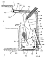
- FIG. 7 shows a partial sectional view of the terminal connection space 18 of another service switching device 1 according to the invention. Only the first, lower terminal connection 10 is shown. The second, upper terminal connection 10 'is designed accordingly, but with a shortened distance surface of its associated second terminal cover.
- the service switching device 1 has an insulating housing formed from two housing parts 2 with a front side 304, a rear front side 305, a mounting side 6, a front narrow side 7, a rear narrow side 8, and two broad sides 9, of which in the view of Figure 1 only one, lying in the drawing plane, is shown.
- the terminal connection space 18 is laterally, ie towards the broad side, limited by the housing broad sides 9 of the insulating housing 3.
- an opening 20 of the terminal connection space 18 is formed through a recess in the rear front side 305 of the housing part 2, through which the terminal connection 10 fixed in position in the terminal connection space 18 is accessible for the connection of connection conductors 14.
- a housing-side section 356 of the rear front side 305 connects.
- an opening 20 is formed on the rear front side 305 in the region between the end of the housing-side section 356 facing away from the front narrow sides 7 and the rear narrow side 8.
- the opening 20 of the terminal connection space 18 extends over the abutting edges between the rear narrow side 8 and the rear front side 305 away still in the rear narrow side 8 inside. This has the advantage that increased flexibility is given for the connection direction of the connection conductor 14.
- the terminal connection 10 described below essentially corresponds to the terminal connection already described above in FIGS. 1-6. It comprises a bus bar 102 and a clamping spring 312.
- the terminal connection 10 is fixed in position in the inside of the broad side 9 by means of webs 104 and pins 106, 108 in a manner known per se in the terminal connection space 18.
- the fixed in the terminal connection space 18 terminal terminal 10 is located in the region of the abutting edge between the rear narrow side 8 and the rear attachment side. 6
- the busbar 102 of the terminal terminal 10 comprises a connection end 112 and a subsequent discharge region 114. At the connection end 112, it has a window-like recess 116 with a support edge 118 and a clamping edge 120 opposite the support edge 118. The clamping edge 120 is located at the transition of the connection end 112 into the discharge region 114.
- the clamping spring 12 has a support leg 212, with which it is supported on the support edge 118 of the bus bar 102.
- the support can be made so that the support leg 212 has at its free end an upstand, with which it includes the support edge 118 for the purpose of supporting partially.
- a curved piece 214 and thereon a clamping leg 216 connects.
- the conductor end of a connecting conductor (not shown here) is introduced from the side of the elbow 214 forth in the window-like recess 116 and is clamped between the clamping leg 216 and acting as an abutment clamping edge 120.
- the free end of the clamping leg 216 passes through the window-like recess 116th
- the busbar 102 has approximately a U-shaped basic shape, wherein the terminal end 112 forms the first U-leg, and the discharge region 114 is formed by a transverse web 220 and the second U-leg 222. At the free end of the second U-leg 222 a Aufkantung 224 is attached. At this Aufkantung 224 further connection conductors can be attached, with which the terminal connection 10 is connected to other modules within the switching device housing, such as the trigger assemblies. In particular, the connection conductors of this upstand can be welded or brazed, also screwing is possible.
- the upstand at the free end of the second U-leg 222 is extended to a discharge rail 226.
- the discharge rail 226 is thus positively connected to the second U-leg 222; it points approximately perpendicularly from this towards the window-like recess 116 and projects beyond it.
- a first partial clamping leg 217 which merges at a bending edge 219 in a second partial clamping limb 218 bent from the first partial clamping leg 217, initially adjoins the curved piece 214, so that the first and the second partial clamping legs 217 , 218 take an obtuse angle with each other.
- the opening of the obtuse angle points in the insertion direction of the connecting conductor, the bending edge 219 is located approximately in the middle of the clamping leg 216.
- the opening 20 of the terminal connection space 18 is covered by a terminal cover part 22 pivotally connected to the housing part 2.
- the terminal cover part 22 comprises a longitudinally extending in the direction of the rear narrow side 8, via a pivot pin 232 to the housing part 2 pivotally coupled first part body 322 and at its free end via a hinge 352 pivotally coupled closure member 354, which is approximately parallel to the rear front side 305th runs. To improve the mobility in the hinge 352 this is designed as a film hinge.
- the first part body 322 includes a first cover plate 323 which covers the terminal connection space 18 in the lower part of the narrow side 8 adjacent to the attachment side 6 and which carries an approximately tubular counterpart to the hinge pin 232 with which it is pivotally coupled to the hinge pin is.
- the first cover plate 323 has an externally accessible, manually operable pressure surface 330.
- the first cover plate 323 is connected via a pointing into the housing intermediate piece 325 with a spacer surface 338, which is also parallel to the rear narrow side 8 in the direction extends the front side 305 and covers the terminal connection space 18 in the upper part of the narrow side 8 adjoining the rear front side 305.
- the closure part 354 and the housing-side part 356 of the rear front side thus together form the rear front side 305.
- the closure member 354 carries laterally, in the direction of the broad sides 9 facing, projecting pins 358.
- a backdrop-like guide 360 is mounted, in such a way that the pins 358 included in the guide 360.
- the closure member 354 is slid behind the housing-side part 356 of the rear front side 305 and guided by the slide-like guide 360 parallel to this.
- the angle between the closure part 354 and the spacer surface 338 changes.
- closure part 354 and the spacer surface 338 form an acute angle with one another, which is opened into the interior of the housing.
- the closure member 354 and the spacer surface 338 form an obtuse angle with an opening into the housing interior.
- the closure member 354 and the spacer surface 338 Upon actuation of the terminal cover member and concomitant pivoting about the pivot pin 232, the closure member 354 and the spacer surface 338 also pivot against each other about the film hinge 352.
- the closure part 354 can thus save space behind the housing-side part 356 of the rear front side 305 in order to save space.
- the intermediate piece 325 has an outwardly directed connection surface 324.
- connection surface 324 In the connection surface 324, at least one connection opening 26 is present. Starting from the connection opening 26, the intermediate piece 325 is penetrated by a tubular recess 28 which, starting approximately perpendicularly from the connection surface 324, penetrates the intermediate piece 325 and thus serves as guide means for a connection conductor to be connected to the terminal connection 10.
- connection conductor is guided through the connection opening 26 in the terminal cover part 22 and, after leaving the tubular recess 28, strikes the clamping leg 216 of the clamping spring 312.
- the terminal conductor is a rigid conductor, then by means of the terminal conductor alone the clamping leg 216 of the clamping spring 312 can be pushed away from the clamping edge 120 so far that the terminal conductor between the free end of the clamping leg 216 and the clamping edge 120 in the window-like recess 116 inserted and clamped is.
- the window-like recess 116 In a flexible connection conductor, the window-like recess 116 must first be opened in another way.
- the terminal cover member 22 carries on the intermediate piece 325 a directed towards the clamping leg 216 toward nose 30, which serves as a spring actuating means.
- the nose 30 can of course also be other protruding components or components, in particular the function of the nose 30 could also be formed by a collar which surrounds the outlet opening of the tubular recess 28.
- the terminal cover member 22 By pressing on the pressure surface 330 or on the spacer surface 338, the terminal cover member 22 is pivoted inwardly, and via the nose 30 of the clamping leg 216 so far pushed away from the clamping edge 120 that the window-like recess 116 is free for the insertion of the connecting conductor, see Figure 8.
- the nose 30 is formed on the terminal cover 22 and formed so that they act upon the pivoting of the cover against the clamping spring opening this close to the bending edge 219.
- first and second partial clamping legs 217, 218 form an angle of about 160 °.
- Compared to an otherwise unchanged clamping spring with straight, unbent clamping leg 216 halves the insertion force of the angle, the operating force at maximum terminal opening.
- the opening movement of the terminal cover member 22 may also be effected by a commercially available slotted or Phillips screwdriver 364.
- a commercially available slotted or Phillips screwdriver 364 For this purpose, it is placed on the spacer surface 338 at an acute angle into a receptacle opening 350 (slotted, cross-shaped or spherical recess) which is suitable for receiving, and the clamp is opened by a pressure movement with the screwdriver 364.
- connection opening 26 and only one tubular recess 28 is shown in the illustration according to FIGS. 7 and 8, it is of course also possible to provide two or more such connection openings and recesses for receiving and connecting a plurality of connection conductors in the intermediate piece 325. All connected connection conductors can be connected with a common clamping spring via their clamping legs 216. Upon actuation of the terminal cover 22 then all connected conductors are released simultaneously and can be solved simultaneously.
- the terminal cover part 22 with the first part body 322, the hinge 352 and the closure part 354 consists in a further embodiment, for which, however, the same figures 7 and 8 apply as schematic drawings, of two material components with different mechanical properties.
- the result is a hard / soft connection.
- the hard component is the main ingredient. From her, the first part of body 322 is made. It serves to transmit the actuating forces to the clamping spring 312 and thereby prevent or at least minimize bending of the component.
- the soft component is used.
- the hinge 352 need not necessarily be a living hinge. Because the mobility of the hinge is ensured by the choice of a flexible material in the hinge area, not only by the thickness of the hinge.
- a flexibility of the closure part 354 further contributes to this, when it is in the slide-like guide 360 in the direction of the front narrow side. 7 shifted parallel to the rear front side 305, could also bend something in itself, and thus can rest even lighter and closer to the front narrow side 305.
Abstract
Description
Die Erfindung betrifft ein Installationsschaltgerät mit einem Gehäuse und mit zwei schraubenlosen Klemmenanschlüssen mit jeweils wenigstens einer Klemmfeder zum Anschließen von Anschlussleitern, die in einem Klemmenanschlussraum des Gehäuses lagefixiert ist, gemäß dem Oberbegriff des Anspruchs 1.The invention relates to an installation switching device with a housing and with two screwless terminal connections, each with at least one clamping spring for connecting connecting conductors, which is fixed in position in a terminal connection space of the housing, according to the preamble of
Ein gattungsgemäßes Installationsschaltgerät umfasst innerhalb seines Gehäuses wenigstens eine Kontaktstelle mit wenigstens einem festen und einem beweglichen Kontaktstück, über die ein von einer Eingangs - zu einer Ausgangsklemme führender Strompfad geöffnet und geschlossen werden kann. Die Kontaktstelle wird im allgemeinen von einem Schaltwerk mit Verklinkungsstelle betätigt. Ein gattungsgemäßes Installationsschaltgerät kann weiterhin Auslösevorrichtungen umfassen, beispielsweise einen thermischen Auslöser oder einen magnetischen Schnellauslöser, die bei Auftreten eines Kurzschluss - oder Fehlerstromes in dem Strompfad auf die Kontaktstelle beziehungsweise das Schaltwerk einwirken, so dass die Kontaktstelle geöffnet wird.A generic installation switching device comprises within its housing at least one contact point with at least one fixed and one movable contact piece, via which a current leading from an input to an output terminal current path can be opened and closed. The contact point is generally operated by a rear derailleur with Verklinkungsstelle. A generic service switching device may further comprise tripping devices, for example a thermal release or a magnetic quick release, which act on the contact point or the rear derailleur when a short circuit or fault current occurs in the current path, so that the contact point is opened.
Bei manchen gattungsgemäßen Installationsschaltgeräten wird neben dem stromführenden Pol auch noch in der Nulleiter angeschlossen. Bei solchen Geräten ist es dann erforderlich, dass an der Klemmenanschlussseite zwei Leiter dicht nebeneinander anschließbar sind, allerdings an der Anschlussstelle des Installationsschaltgerätes elektrisch voneinander isoliert bleiben.In some generic service switching devices in addition to the current-carrying pole is still connected in the neutral. In such devices, it is then necessary that two conductors can be connected close to each other at the terminal connection side, but remain electrically isolated from one another at the connection point of the service switching device.
Zur Verbindung mit äußeren Anschlussleitern werden in gattungsgemäßen Installationsschaltgeräten neben Schraubklemmen auch schraubenlose Klemmanschlüsse eingesetzt. Als Klemmelemente können dabei Steckklemmen oder Federzugklemmen zum Einsatz kommen. Im Prinzip können diese das Anschließen von Anschlussleitern erheblich vereinfachen, doch sind heute bekannte Installationsschaltgeräte mit schraubenlosen Klemmenanschlüssen mit Nachteilen behaftet.For connection with external connection conductors, screw-type terminal connections are used in addition to screw terminals in generic service switching devices. As clamping elements can thereby plug terminals or spring terminals for Use come. In principle, these can greatly simplify the connection of connecting conductors, but today known installation switching devices with screwless terminal connections are subject to disadvantages.
Aus der
Die
Es ist daher die Aufgabe der vorliegenden Erfindung, ein gattungsgemäßes Installationsschaltgerät zu schaffen, bei dem zwei schraubenlose Klemmenanschlüsse an einer Seite des Installationsschaltgerätes in einem gemeinsamen Klemmenanschlussraum einander zugeordnet sind und die Klemmenanschlüsse auf einfache und kostengünstige Art und Weise so gestaltet ist, dass das werkzeugfreie Einführen und Entfernen von Anschlussleitungen möglich wird.It is therefore an object of the present invention to provide a generic service switching device, in which two screwless terminal connections are assigned to one another on one side of the service switching device in a common terminal connection space and the terminal connections in a simple and cost-effective manner is designed so that the tool-free insertion and removal of leads is possible.
Die Aufgabe wird gelöst durch ein gattungsgemäßes Installationsschaltgerät mit den kennzeichnenden Merkmalen des Anspruchs 1. Erfindungsgemäß also ist der Klemmenanschlussraum zu den Gehäusebreitseiten und zur Frontseite hin offen, und die beiden Klemmenanschlüsse sind quer zur Breitseite nebeneinander und in der Höhe über der Befestigungsseite gegeneinander verschoben, und jeder der beiden Klemmenanschlüsse ist durch ein schwenkbar mit dem Gehäuse verbundenes Klemmenabdeckteil bedeckt. Jedes Klemmenabdeckteil weist eine Anschlussfläche mit einer der Anzahl anzuschließender Anschlussleiter entsprechenden Anzahl von Anschlußöffnungen sowie an jeder Anschlußöffnung angeformte Führungsmittel für die Anschlussleiter auf. Weiterhin weist jedes Klemmenabdeckteil zwei Seitenflächen auf, die bei aufgesetztem Klemmenabdeckteil den ihm zugeordneten Klemmenanschluss seitlich in Richtung der Breitseiten hin abdecken.The object is achieved by a generic service switching device with the characterizing features of
Gemäß einer vorteilhaften Ausführungsform der Erfindung sind an das Klemmenabdeckteil Federbetätigungsmittel angeformt und so ausgebildet, dass sie beim Verschwenken des Abdeckteils gegen die Klemmfeder diese öffnend beaufschlagen.According to an advantageous embodiment of the invention spring actuation means are formed on the terminal cover and formed so that they act upon opening the cover against the clamping spring opening.
Eine weitere sehr vorteilhafte Ausführungsform der Erfindung sieht vor, dass die Führungsmittel röhrenartige, einen Einführkanal bildende Hohlkörper sind, die gleichzeitig als Federbetätigungsmittel für die Klemmfeder dienen.Another very advantageous embodiment of the invention provides that the guide means are tube-like, an insertion channel forming hollow body, which also serve as a spring actuating means for the clamping spring.
Jeder Klemmenanschluss eines erfindungsgemäßen Installationsschaltgerätes umfasst sehr wenige Bauteile, nämlich im wesentlichen nur die Klemmfeder, eine Stromschiene mit einer Klemmkante, gegen die die Klemmfeder den anzuschließenden Anschlussleiter klemmt, und das Klemmenabdeckteil. Ein erfindungsgemäßes Installationsschaltgerät umfasst zwei solcher Klemmenanschlüsse, die an einer Anschlussseite des Gerätes nebeneinander angeordnet sind. Er ist daher sehr einfach und kostengünstig zu fertigen.Each terminal connection of a service switching device according to the invention comprises very few components, namely essentially only the clamping spring, a busbar with a clamping edge against which the clamping spring clamps the connecting conductor to be connected, and the terminal cover. An inventive installation switching device comprises two such terminal connections, which are arranged side by side on a connection side of the device. It is therefore very easy and inexpensive to manufacture.
Gemäß einer besonders vorteilhaften Ausführungsform sind die beiden Klemmenanschlüsse auch in der Höhe über der Befestigungsseite gegeneinander verschoben und damit versetzt. Auf diese Weise wird die Luft- und Kriechstrecke zwischen den beiden Klemmenanschlüssen verlängert, wodurch die elektrische Isolierung zwischen den beiden Klemmenanschlüssen weiter abgesichert wird.According to a particularly advantageous embodiment, the two terminal connections are also offset in height above the mounting side against each other and thus offset. In this way, the creepage and clearance between the two terminal connections are lengthened, further securing the electrical insulation between the two terminal connections.
Das Klemmenabdeckteil ist so gestaltet, dass es mehrere Funktionen in einem Bauteil verwirklicht:
- Die an dem Klemmenabdeckteil an jeder Anschlussöffnung angeformten Führungsmittel sorgen für die Führung des Anschlussleiters hin zur Klemmfeder in dem gewünschten Einführungswinkel. Weder die Stromschiene, noch die Klemmfeder selbst brauchen weitere Führungsmittel zur Führung des Anschlussleiters vorzuweisen.
- Mehrere Anschlussleiter werden durch mehrere Anschlussöffnungen eingeführt und dabei gleichzeitig auseinander gehalten. Somit ist auch bei mehreren anzuklemmenden Leiterenden ein individuelles Einführen jedes einzelnen Leiterendes möglich, ohne dass auf Seiten der Klemmfeder oder der Stromschiene weitere Maßnahmen zum Auseinanderhalten der einzelnen Leiter erforderlich sind.
- Durch die gemäß einer vorteilhaften Ausführungsform gleichzeitig an dem Klemmenabdeckteil angeformten Federbetätigungsmittel wird das Klemmenabdeckteil gleichzeitig zum Öffnungswerkzeug für die Klemmfeder. Ein separates Betätigungswerkzeug, beispielsweise ein Schraubendreher, ist nicht mehr erforderlich, um die Klemmfeder zu öffnen. Dadurch wird das Einführen und das wieder Entnehmen von Anschlussleitern stark vereinfacht.
- The integrally formed on the terminal cover at each connection opening guide means to guide the connection conductor towards the clamping spring in the desired insertion angle. Neither the busbar, nor the clamping spring itself need to show further guidance means for guiding the connecting conductor.
- Several connection conductors are inserted through several connection openings while at the same time kept apart. Thus, it is also to be clamped at several Ladder ends an individual insertion of each conductor end possible without further action on the side of the clamping spring or the busbar to keep apart of the individual conductors are required.
- By virtue of the spring actuation means formed integrally on the terminal cover part according to an advantageous embodiment, the terminal cover part simultaneously becomes the opening tool for the clamping spring. A separate operating tool, such as a screwdriver, is no longer required to open the clamping spring. This greatly simplifies the insertion and removal of connecting leads.
Ein erfindungsgemäßes Installationsschaltgerät weist insgesamt den Vorteil auf, dass an einer Anschlussseite und in einem Klemmenanschlussraum zwei Klemmenanschlüsse auf einfache Art und Weise und von außen sehr bequem zugänglich nebeneinander angebracht sind, wobei die beiden Klemmenanschlüssen elektrisch voneinander isoliert und unabhängig voneinander ohne Werkzeug betätigbar sind. Sowohl zum Einführen als auch zum Entfernen von Anschlussleitern mit festem und mit flexiblem Anschlussende, in bzw. aus dem Klemmenanschluss wird kein externes Werkzeug benötigt. Die Klemmenanschlüsse sind mit wenigen vorgefertigten Bauteilen einfach aufzubauenAn installation switching device according to the invention has the overall advantage that two terminal connections are mounted on one connection side and in a terminal connection space in a simple manner and from the outside very convenient accessible side by side, the two terminal terminals are electrically isolated from each other and independently operable without tools. For insertion as well as removal of fixed and flexible terminal connection leads into or out of the terminal connection, no external tool is required. The terminal connections are easy to set up with just a few prefabricated components
Gemäß einer vorteilhaften Ausführungsform der Erfindung ist jedes Klemmenabdeckteil durch die ihm zugeordnete Klemmfeder entgegen der Einführrichtung des externen Anschlussleiters federnd beaufschlagt und gegen diese Klemmfeder drückbar. Dabei kann in besonders vorteilhafter Weise das Klemmenabdeckteil durch die ihm zugeordnete Klemmfeder gegen einen als Anschlag dienenden Vorsprung der Gehäusewand federnd beaufschlagt sein. Somit wird das Klemmenabdeckteil durch die federnde Beaufschlagung der ihm zugeordneten Klemmfeder in einer definierten Ausgangsposition gehalten. Die Ausgangsposition ist dabei die Schließposition der Klemmfeder.According to an advantageous embodiment of the invention, each terminal cover is resiliently acted upon by the associated clamping spring against the insertion direction of the external connection conductor and pressed against this clamping spring. In this case, in a particularly advantageous manner, the terminal cover part can be resiliently acted upon by the clamping spring assigned to it against a projection of the housing wall serving as a stop. Thus, the terminal cover is held by the resilient application of the associated clamping spring in a defined starting position. The starting position is the closed position of the clamping spring.
Das Klemmenabdeckteil kann besonders einfach gestaltet werden und ist beispielsweise als kostengünstiges Spritzgußteil herstellbar.The terminal cover can be made particularly simple and can be produced for example as a cost-effective injection molded part.
Zur Druckbetätigung des Klemmenabdeckteils kann vorgesehen sein, dass das Klemmenabdeckteil eine von außen zugängliche, manuell betätigbare Druckfläche aufweist.For the pressure actuation of the terminal cover part it can be provided that the terminal cover part has an externally accessible, manually operable pressure surface.
Eine weitere vorteilhafte Variante der Erfindung ist dadurch gekennzeichnet, dass der Klemmenanschlussraum zwischen den beiden Klemmenanschlüssen eine parallel zu den Breitseiten verlaufende Isolierplatte umfasst. Dadurch wird eine Berührung und damit ein elektrischer Kontakt zwischen den beiden Klemmenanschlüssen, beispielsweise zwischen den beiden Stromschienen, vermieden. Außerdem wirkt die Isolierplatte mechanisch stabilisierend.A further advantageous variant of the invention is characterized in that the terminal connection space between the two terminal connections comprises an insulating plate running parallel to the broad sides. As a result, a contact and thus an electrical contact between the two terminal connections, for example between the two busbars avoided. In addition, the insulating acts mechanically stabilizing.
Um im Betriebszustand, also nach der Fertigmontage des Installationsschaltgerätes, auf einfache Art und Weise für einen Spannungsprüfer Zugang zu dem Klemmenanschluss zu gewährleisten, kann das Klemmenabdeckteil eine Testöffnung für eine elektrische Kontaktierung des Klemmmenanschlusses aufweisen.In order to ensure access to the terminal connection in a simple manner for a voltage tester in the operating state, ie after the final installation of the service switching device, the terminal cover part can have a test opening for electrical contacting of the terminal connection.
Eine weitere vorteilhafte Variante der Erfindung ist dadurch gekennzeichnet, dass in der Nähe eines Klemmenabdeckteiles eine Einstellöffnung in die Gehäusewand eingebracht ist. Damit ist es möglich, während der Fertigung oder im eingebauten Zustand des fertig montierten Schaltgerätes mit einem Werkzeug ins Innere des Schaltgerätes einzugreifen, um auf ein dort in der Nähe der Einstellungsöffnung angeordnetes Justagemittel zuzugreifen.A further advantageous variant of the invention is characterized in that an adjustment opening is made in the vicinity of a terminal cover part in the housing wall. This makes it possible to intervene during manufacture or in the installed state of the finished mounted switching device with a tool inside the switching device to access an arranged there in the vicinity of the adjustment opening adjustment means.
Bezüglich der räumlichen. Anordnung der Anschlussfläche des Klemmenabdeckteils bezogen auf die Frontseite des Gehäuses und der Führungsmittel gegenüber der Anschlussfläche sieht eine mögliche Ausführungsform der Erfindung vor, dass die Anschlussfläche des Klemmenabdeckteils etwa parallel zur hinteren Frontseite verläuft und die Führungsmittel gegenüber der Anschlussfläche des Klemmenabdeckteils geneigt sind. Der Neigungswinkel für die Führungsmittel wird beispielsweise danach gewählt, dass die Anschlussleiter beim Reiheneinbau eines erfindungsgemäßen Installationsschaltgerätes, beispielsweise in einen Verteilerkasten, gut zugänglich bleiben und die Anschlussleiter nicht zu stark nach oben hin abgeknickt werden.Regarding the spatial. Arrangement of the terminal surface of the terminal cover with respect to the front of the housing and the guide means relative to the pad provides a possible embodiment of the invention that the terminal surface of the terminal cover is approximately parallel to the rear front side and the guide means are inclined relative to the terminal surface of the terminal cover. The angle of inclination for the guide means is selected, for example, according to the fact that the connection conductors remain easily accessible when mounting a service switching device according to the invention, for example in a distribution box, and the connection conductors are not bent too much towards the top.
Eine weitere vorteilhafte Ausführungsform sieht diesbezüglich vor, dass die Anschlußfläche des Klemmenabdeckteils gegenüber der hinteren Frontseite geneigt und die Führungskanäle in etwa senkrecht zu der Anschlussfläche verlaufen. Der Neigungswinkel, unter dem die Anschlussleiter relativ zur Federklemme eingeführt werden, wird in dieser Ausführungsform durch den Neigungswinkel der Führungskanäle bestimmt.A further advantageous embodiment provides in this respect that the terminal surface of the terminal cover part inclined relative to the rear front side and the guide channels extend approximately perpendicular to the connection surface. The inclination angle at which the leads are inserted relative to the spring clip is determined in this embodiment by the angle of inclination of the guide channels.
Es wäre selbstverständlich auch eine Kombination beider oben gezeigten Möglichkeiten denkbar, bei der sowohl die Anschlussfläche des Klemmenabdeckteils gegenüber der hinteren Frontseite, als auch die Führungskanäle gegenüber der Anschlussfläche geneigt sind.It would of course also a combination of the above two options are conceivable in which both the connection surface of the terminal cover opposite the rear front side, and the guide channels are inclined relative to the connection surface.
Um auf Wunsch, etwa aus Gründen der Redundanz, zusätzlich die Betätigung der Federklemme durch ein externes Werkzeugs zu ermöglichen, kann gemäß einer weiteren Ausführungsform des erfindungsgemäßen Installationsschaltgerätes das Klemmenabdeckteil eine Eingriffsöffnung für ein Betätigungswerkzeug aufweisen. Durch diese Eingriffsöffnung hindurch kann dann mit dem Betätigungswerkzeug, beispielsweise einem Schraubendreher, die Klemmfeder in ihre Öffnungsposition verbracht werden.In order to enable on request, for reasons of redundancy, in addition, the operation of the spring clamp by an external tool, according to another embodiment of the service switching device according to the invention, the terminal cover having an engagement opening for an operating tool. Through this engagement opening can then be spent with the actuating tool, such as a screwdriver, the clamping spring in its open position.
Gemäß einer weiteren, sehr vorteilhaften Ausführungsform ist mit dem freien, der Frontseite zuweisenden Ende eines ersten Teilkörpers jedes Klemmenabdeckteils verschwenkbar ein Verschlussteil gekoppelt, welches jeweils den Klemmenanschlussraum an der Frontseite im Zusammenwirken mit einem gehäusefesten Frontseitenende bedeckt, wobei bei Betätigung jedes Klemmenabdeckteils das Verschlussteil mit dem gehäusefesten Frontseitenende zumindest teilsweise überlappt.According to a further, very advantageous embodiment, with the free, the front facing end of a first body part of each terminal cover pivotally coupled a closure member which covers the terminal connection space on the front side in cooperation with a housing-fixed front end, wherein upon actuation of each terminal cover the closure member with the housing-side front end at least partially overlapped.
Das jeweilige Verschlussteil und das gehäusefeste Teil der Frontseite bilden zusammen die Frontseite. Das jeweilige Verschlussteil wirkt somit in Ergänzung zu dem gehäusefesten Teil als klemmenabdeckteilseitiges Teil der Frontseite.The respective closure part and the housing-fixed part of the front side together form the front side. The respective closure part thus acts as a supplement to the housing-fixed part as klemmenabdeckteilseitiges part of the front.
Gemäß einer besonders vorteilhaften Ausführungsform ist das Verschlussteil plattenförmig ausgebildet. Es kann dabei vorteilhafterweise in demselben Spritzgussvorgang wie das Klemmenabdeckteil hergestellt sein.According to a particularly advantageous embodiment, the closure part is plate-shaped. It may advantageously be made in the same injection molding process as the terminal cover.
Sehr vorteilhaft ist insbesondere eine Ausführungsform, bei der das jeweilige Verschlussteil mittels eines Scharniers, beispielsweise eines Filmscharniers mit dem jeweiligen Klemmenabdeckteil gekoppelt ist. Ein solches Filmscharnier lässt sich sehr günstig durch Spritzgießen herstellen.Especially advantageous is an embodiment in which the respective closure part is coupled to the respective terminal cover part by means of a hinge, for example a film hinge. Such a film hinge can be produced very inexpensively by injection molding.
Eine weitere sehr vorteilhafte Ausführungsform der Erfindung ist dadurch gekennzeichnet, dass das jeweilige Verschlussteil über seitlich abstehende Führungszapfen in einer gehäusefesten, kulissenartigen Führung jeweils parallel zur Frontseite verschieblich geführt ist. Das jeweilige Verschlussteil ist dann mit dem jeweils zugehörigen gehäuseseitigen Teil der Frontseite überlappend und verschieblich geführt. Dadurch kann es beim Betätigen des jeweiligen Klemmenabdeckteils hinter das jeweils zugehörige gehäuseseitige Teil der hinteren Frontseite verschwenkt und verschoben werden. Somit ist ein dichtes Abdecken des Klemmenaufnahmeraums zur Frontseite hin bei gleichzeitiger Beweglichkeit des Klemmenabdeckteils und mechanischer Stabilität der hinteren Frontseite gewährleistet.Another very advantageous embodiment of the invention is characterized in that the respective closure part is guided in each case displaceably parallel to the front side via laterally projecting guide pins in a housing-fixed, slide-like guide. The respective closure part is then overlapped and displaceably guided with the respectively associated housing-side part of the front side. It can be pivoted and moved when pressing the respective terminal cover behind the respective associated housing-side part of the rear front. Thus, a tight covering of the terminal receiving space is ensured to the front side with simultaneous movement of the terminal cover and mechanical stability of the rear front.
Durch die Anbringung des Scharniers an dem jeweiligen Verschlussteil kann sich dieses platzsparend parallel zu der Frontseite in einer kulissenartigen Führung bewegen.By attaching the hinge to the respective closure part, this can move in a space-saving parallel to the front in a backdrop-like leadership.
Eine weiterhin sehr vorteilhafte Weiterbildung der Erfindung ist dadurch gekennzeichnet, dass das jeweilige Klemmenabdeckteil im Anschluss an die Anschlussfläche eine Distanzfläche trägt, welche im Bereich der jeweiligen Schmalseite den klemmenabdeckteilseitigen Verschluss des Klemmenaufnahmeraumes bildet, wobei das Verschlussteil an dem der Frontseite zuweisenden Ende der Distanzfläche verschwenkbar gekoppelt ist. Dadurch ist es möglich, die Anschlussfläche in einen der Befestigungsseite näher liegenden Teil der Schmalseitenwand des Schaltgerätes zu verlegen, wenn dies aufgrund einer vorgegebenen Anordnung der Anschlussklemmen im Inneren des Schaltgerätes nahe der Befestigungsseite erforderlich ist.A further very advantageous development of the invention is characterized in that the respective terminal cover part carries a spacer surface following the connection surface, which forms the terminal cover-side closure of the terminal receiving space in the region of the respective narrow side, the closure part being pivotably coupled to the end of the spacer surface facing the front side is. This makes it possible to move the pad in one of the mounting side closer part of the narrow side wall of the switching device, if this is required due to a predetermined arrangement of the terminals in the interior of the switching device near the mounting side.
Gemäß einer besonders vorteilhaften Weiterbildung dieser Ausführungsform ist die Distanzfläche steif ausgeführt ist. Damit wird eine Kraftübertragung auf die Feder der Anschlussklemme auch durch Betätigung des Klemmenabdeckteiles über die Distanzfläche möglich. Dies ist vorteilhaft, wenn die Druckfläche des Klemmenabdeckteils aufgrund der Lage der Anschlussklemme sehr nahe an der Befestigungsseite des Schaltgerätes in der Einbaulage des Schaltgerätes, beispielsweise in einem Installationsverteiler, durch eine Bedienperson nur noch schwer zugänglich ist. Die Distanzfläche kann somit in einem Bereich, der nicht durch einen Anschlussleiter verdeckt ist, als zweite Druckfläche zur Betätigung der Feder genutzt werden.According to a particularly advantageous development of this embodiment, the spacer surface is designed to be stiff. Thus, a power transmission to the spring of the terminal is also possible by pressing the terminal cover over the spacer surface. This is advantageous if the pressure surface of the terminal cover is due to the location of the terminal very close to the mounting side of the switching device in the installed position of the switching device, for example, in an installation distributor, by an operator is difficult to access. The distance surface can thus be used in a region which is not covered by a connecting conductor, as a second pressure surface for actuating the spring.
In einer besonders vorteilhaften weiteren Ausführungsform der Erfindung trägt die Distanzfläche eine Eingriffsöffnung für ein Betätigungswerkzeug. Die Anschlussklemme kann über das Klemmenabdeckteil somit entweder manuell in oder auch mittels eines Werkzeugs betätigt werden.In a particularly advantageous further embodiment of the invention, the spacer surface carries an engagement opening for an actuating tool. The terminal can thus be operated via the terminal cover either manually or by means of a tool.
Gemäß einer weiteren, sehr vorteilhaften Ausführungsform der Erfindung besteht das jeweilige Verschlussteil zumindest im Bereich der Kopplung mit dem ersten Teilkörper aus einem Material, das andere mechanische Eigenschaften aufweist als der erste Teilkörper des Klemmenabdeckteils.According to a further, very advantageous embodiment of the invention, the respective closure part is at least in the region of the coupling with the first part body of a material that has different mechanical properties than the first part body of the terminal cover.
Auch hier bedeckt das Verschlussteil den Klemmenanschlussraum an der Frontseite im Zusammenwirken mit einem gehäusefesten Frontseitenende, wobei bei Betätigung des Klemmenabdeckteils das Verschlussteil mit dem gehäusefesten Frontseitenende zumindest teilsweise überlappt.Again, the closure part covers the terminal connection space on the front side in cooperation with a housing-fixed front side end, wherein upon actuation of the terminal cover part, the closure part at least partially overlaps the housing-fixed front side end.
Das jeweilige Verschlussteil und das gehäusefeste Teil der Frontseite bilden damit zusammen die Frontseite. Das jeweilige Verschlussteil wirkt somit in Ergänzung zu dem gehäusefesten Teil als klemmenabdeckteilseitiges Teil der Frontseite.The respective closure part and the housing-fixed part of the front side together form the front side. The respective closure part thus acts as a supplement to the housing-fixed part as klemmenabdeckteilseitiges part of the front.
Insbesondere vorteilhaft ist dabei eine Ausführungsform, bei der das Scharnier und das jeweilige Verschlussteil im Bereich des Scharniers aus einem Material besteht, das andere mechanische Eigenschaften aufweist als der erste Teilkörper des Klemmenabdeckteils.Particularly advantageous is an embodiment in which the hinge and the respective closure part in the region of the hinge consists of a material which has different mechanical properties than the first part body of the terminal cover part.
Dadurch, dass das jeweilige Verschlussteil zumindest im Bereich der Kopplung mit dem ersten Teilkörper des jeweiligen Klemmenabdeckteils aus einem Material mit anderen mechanischen Eigenschaften als dieses besteht, können die federelastischen Eigenschaften des jeweiligen Verschlussteils und dessen Kopplung an den jeweils ersten Teilkörper unabhängig von denen des jeweils ersten Teilkörpers des Klemmenabdeckteils festgelegt und für den Verwendungszweck optimiert werden. Dies ist insbesondere dann vorteilhaft, wenn an den jeweils ersten Teilkörper des Klemmenabdeckteils andere, manchmal sogar gegenläufige, mechanische Anforderungen gestellt sind als an das Verschlussteil.Because the respective closure part, at least in the region of the coupling with the first part body of the respective terminal cover part, consists of a material with different mechanical properties than the latter, the resilient properties of the respective closure part and its coupling to the respectively first part body can be independent of those of the respective first part Part body of the terminal cover part set and optimized for the intended use. This is particularly advantageous if other, sometimes even opposite, mechanical requirements are placed on the respective first part body of the terminal cover part than on the closure part.
Dies kann dann der Fall sein, wenn das jeweilige Klemmenabdeckteil bei einer Betätigung, also einem Verschwenken ins Innere des Schaltgerätes hinein, gleichzeitig die jeweils zugehörige Klemmfeder entgegen deren rückstellenden Federkraft öffnend betätigt.This can then be the case when the respective terminal cover at an actuation, ie a pivoting into the interior of the switching device inside, simultaneously activates the respectively associated clamping spring against its restoring spring force.
Dies kann beispielsweise durch an das jeweilige Klemmenabdeckteil in geeigneter Lage angeformte Federbetätigungsmittel, die bei einem Verschwenken des Klemmenabdeckteils auf die Klemmfeder einwirken, bewirkt sein.This can be effected, for example, by spring actuation means integrally formed on the respective terminal cover part in a suitable position and acting upon pivoting of the terminal cover part onto the clamping spring.
In diesem Fall muss der erste Teilkörper des jeweiligen Klemmenabdeckteils eine hohe Steifigkeit aufweisen, damit die Kraft zur Öffnung der jeweiligen Klemmfeder ohne Deformationen des jeweiligen Klemmenabdeckteils übertragen werden kann.In this case, the first sub-body of the respective terminal cover has a high rigidity, so that the force can be transmitted to the opening of the respective clamping spring without deformation of the respective terminal cover.
Das jeweilige Verschlussteil soll jedoch flexibel sein, zumindest jedoch flexibel an den ersten Teilkörper die des Klemmenabdeckteils gekoppelt sein, damit es sich beim Verschwenken des Klemmenabdeckteils platzsparend in der kulissenartigen Führungen hinter das gehäusefeste Frontseitenende schieben kann.However, the respective closure part should be flexible, but at least flexibly coupled to the first part of the body of the terminal cover so that it can slide to save space during the pivoting of the terminal cover in the backdrop-like guides behind the housing-side front end.
Beim Verschwenken des jeweiligen Klemmenabdeckteils ins Geräteinnere hinein wird sich nämlich zwangsläufig der Winkel zwischen dem Verschlussteil und dem ersten Teilkörper des jeweiligen Klemmenabdeckteils ändern.During pivoting of the respective terminal cover part into the interior of the device, the angle between the closure part and the first part body of the respective terminal cover part will inevitably change.
Denn das Verschlussteil soll möglichst parallel zum dem gehäusefesten Frontseitenende verlaufen. Doch der Winkel zwischen dem ersten Teilkörper des Klemmenabdeckteils und dem gehäusefesten Frontseitenende ändert sich beim Verschwenken des Klemmenabdeckteils. An der Koppelstelle ist daher eine Beweglichkeit des Verschlussteils gegenüber dem ersten Teilkörper des Klemmenabdeckteils erforderlich, die nur durch eine Flexibilität des Materials an dieser Stelle erreicht werden kann.Because the closure part should be as parallel as possible to the housing-fixed front end. However, the angle between the first sub-body of the terminal cover and the housing-fixed front end changes during pivoting of the terminal cover. Therefore, a mobility of the closure part relative to the first part body of the terminal cover part is required at the coupling point, which can only be achieved by a flexibility of the material at this point.
Gemäß einer besonders vorteilhaften Weiterbildung der Erfindung ist die Distanzfläche steif ausgeführt, und das Verschlussteil ist zumindest im Bereich der Kopplung mit der Distanzfläche aus einem weichen Material, welches weicher als die Distanzfläche ist, ausgeführt.According to a particularly advantageous embodiment of the invention, the spacer surface is designed stiff, and the closure part is at least in the region of the coupling with the spacer surface made of a soft material, which is softer than the spacer surface executed.
Damit sind die beiden widersprechenden Anforderungen an unterschiedliche Teilkörper des Klemmenabdeckteils erfüllt. Ein einziges Bauteil, das jeweilige Klemmenabdeckteil, hat bereichsweise unterschiedliche Materialeigenschaften. Durch den steifen Teilbereich wird eine Kraftübertragung auf die jeweilige Feder der Anschlussklemme auch durch Betätigung des Klemmenabdeckteiles über die Distanzfläche möglich. Das Verschlussteil, der zweite Teilbereich, kann sich dennoch leicht abbiegen und parallel zur vorderen Frontseiten und hinter diese verschieben.Thus, the two conflicting requirements for different body parts of the terminal cover are met. A single component, the respective terminal cover, has different material properties in some areas. Due to the rigid part of a transmission of force to the respective spring of the terminal is also possible by pressing the terminal cover over the spacer surface. The closure part, the second part, can nevertheless turn easily and move parallel to the front panels and behind them.
In einer besonders vorteilhaften Ausführungsform der Erfindung ist das Klemmenabdeckteil mit dem daran gekoppelten Verschlussteil in einem Zweikomponenten-Spritzgußverfahren hergestellt. In diesem Verfahren können Materialien mit unterschiedlichen mechanischen Eigenschaften, also beispielsweise harte und weiche Kunststoffe, beim Spritzgiessen zusammengefügt werden.In a particularly advantageous embodiment of the invention, the terminal cover part is produced with the closure part coupled thereto in a two-component injection molding process. In this process, materials with different mechanical properties, so for example hard and soft plastics, are joined together in injection molding.
Bezüglich einer vorteilhaften Ausgestaltung der Klemmenanschlüsse umfasst jeder Klemmenanschluss eines erfindungsgemäßen Installationsschaltgerätes eine als Druckfeder auf das Leiterende einwirkende Klemmfeder zum Festklemmen des Leiterendes an einem Widerlager, wobei der Klemmanschluss eine Stromschiene mit einem Anschlussende und einem daran anschließenden Ableitbereich umfasst. Die Stromschiene weist am Anschlussende eine fensterartige Aussparung mit einer Stützkante und einer der Stützkante gegenüberliegenden Klemmkante am Übergang des Anschlussendes in den Ableitbereich auf. Die Klemmfeder weist weiterhin einen Stützschenkel auf, mit dem sie an der Stützkante der Stromschiene abgestützt ist. An den Stützschenkel schließt ein Bogenstück und daran ein Klemmschenkel an, so dass das Leiterende zwischen dem Klemmschenkel und der Klemmkante als Widerlager festklemmbar ist. Das Leiterende ist von der Seite des Bogenstücks her in die fensterartige Aussparung einführbar.With regard to an advantageous embodiment of the terminal connections, each terminal connection of an installation switching device according to the invention comprises a compression spring acting on the conductor end clamping spring for clamping the conductor end to an abutment, wherein the clamping connection comprises a busbar with a terminal end and an adjoining discharge area. At the connection end, the busbar has a window-like recess with a supporting edge and a clamping edge opposite the supporting edge at the transition of the connection end into the diverting region. The clamping spring also has a support leg, with which it is supported on the support edge of the busbar. At the support leg includes a curved piece and a clamping leg, so that the conductor end between the clamping leg and the clamping edge is clamped as an abutment. The conductor end can be inserted from the side of the elbow piece into the window-like recess.
Gemäß einer vorteilhaften Ausführungsform der Erfindung schließt an das jeweilige Bogenstück ein erster Teil-Klemmschenkel an, der an einer Biegekante in einen von dem jeweiligen ersten Teil-Klemmschenkel abgebogenen zweiten Teil-Klemmschenkel übergeht, so dass der jeweils erste und der zweite Teil-Klemmschenkel einen stumpfen Winkel miteinander einnehmen, dessen Öffnung in die Einführrichtung des Anschlussleiters weist.According to an advantageous embodiment of the invention connects to the respective elbow a first part-clamping leg, which merges at a bending edge in a bent from the respective first part-clamping leg second part-clamping legs, so that the respective first and the second part-clamping legs a occupy obtuse angle with each other, the opening points in the insertion direction of the connecting conductor.
Der stumpfe Winkel zwischen dem jeweils ersten und dem jeweils zweiten Teil-Klemmschenkel bietet den Vorteil, dass der Angriffspunkt in die Nähe des Federbetätigungsmittel des in die Nähe der Biegekanten gelegt werden kann. Dadurch kann der Anlagepunkt des Federbetätigungsmittels einen größeren Abstand zum Drehpunkt des Klemmschenkels an dem Bogenstück aufweisen, ohne dass die dadurch erreichbare maximale Klemmenöffnung kleiner wird, und ohne dass das Federbetätigungsmittel einem Anschlussleiter mit großen Querschnitt im Wege stünde. Ein größerer Abstand zwischen dem Anlagepunkt und dem Drehpunkt bedeutet aber ein günstigeres Hebelverhältnis und damit eine geringere Betätigungskraft für den Anwender.The obtuse angle between the respective first and the respective second partial clamping legs offers the advantage that the point of application can be placed in the vicinity of the spring actuating means in the vicinity of the bending edges. Thereby, the contact point of the spring actuating means may have a greater distance to the pivot point of the clamping leg on the elbow without the thereby achievable maximum terminal opening is smaller, and without the spring actuating means would be a connection conductor with a large cross section in the way. However, a greater distance between the contact point and the pivot point means a more favorable lever ratio and thus a lower actuation force for the user.
Eine bevorzugte Ausführungsform ist dadurch gekennzeichnet, dass die Stromschiene in etwa eine U-Form aufweist, wobei das Anschlussende den einen U-Schenkel bildet, und der Ableitbereich durch den Quersteg und den anderen U-Schenkel gebildet ist. Dabei kann am freien Ende des anderen U-Schenkels eine Aufkantung zum Befestigen weiterer Stromleiter, die ins Innere des Installationsschaltgerätes führen, vorgesehen sein.A preferred embodiment is characterized in that the busbar has approximately a U-shape, wherein the terminal end forms the one U-leg, and the diverting region is formed by the transverse web and the other U-leg. It can be provided at the free end of the other U-leg upstand for attaching further conductors that lead into the interior of the service switching device.
Gemäß einer weiteren Ausführungsform kann am freien Ende des anderen U-Schenkels auch eine Ableitschiene angeformt sein. Die Ableitschiene kann dabei etwa senkrecht zu dem anderen U-Schenkel verlaufen und die der Klemmkante gegenüberliegende Seite des Anschlussendes kann an der Ableitschiene abgestützt sein.According to a further embodiment, at the free end of the other U-leg and a discharge bar may be formed. In this case, the discharge bar can run approximately perpendicular to the other U-leg, and the side of the connection end opposite the clamping edge can be supported on the discharge bar.
Ein weiterer Vorteil eines erfindungsgemäßen Installationsschaltgerätes liegt darin, dass der Ableitbereich der Stromschiene zur elektrischen Kontaktierung bei der Kalibrierung des Thermobimetalls genutzt werden kann. Bei bisher bekannten Installationsschaltgeräten ist der Kontaktpunkt für die Kalibrierung des Thermobimetalls an einer anderen Stelle, außerhalb des Zugangsbereiches des Klemmenanschluss, angeordnet und ist nicht über den Klemmenanschluss zugänglich. Da die Kalibrierung des Thermobimetalls nur in fertig montiertem Zustand erfolgen kann, müssen bei bekannten Installationsschaltgeräten im Anschluss an die Kalibrierung die separaten Zugangsöffnungen zu den Kalibrierkontakten durch zusätzliche Abdeckteile abgedeckt werden.Another advantage of a service switching device according to the invention is that the dissipation region of the busbar can be used for electrical contacting during the calibration of the bimetallic strip. In previously known installation switching devices, the contact point for the calibration of the bimetallic strip is located at another location, outside the access area of the terminal connection, and is not accessible via the terminal connection. Since the calibration of the bimetallic strip can only take place in the fully assembled state, in the case of known service switching devices following the calibration, the separate access openings to the calibration contacts must be covered by additional cover parts.
Dies ist bei einem erfindungsgemäßen Installationsschaltgerät nicht nötig. Es werden somit gegenüber aus dem Stand der Technik bekannten Installationsschaltgeräten sowohl Montageteile - nämlich die zusätzlichen Abdeckteile -, als auch Fertigungsschritte bei der Montage eingespart, so dass sich durch die daraus resultierende Montagevereinfachung ein weiterer Vorteil des erfindungsgemäßen Installationsschaltgerätes ergibt.This is not necessary in an installation switching device according to the invention. It is thus compared to both known from the prior art installation switching devices both mounting parts - namely the additional cover - - saved as well as manufacturing steps in the assembly, so that there is a further advantage of the installation switching device according to the invention by the resulting simplification of assembly.
Ein erfindungsgemäßes Installationsschaltgerät kann fertig montiert werden, bis auf die Klemmenabdeckteile. Nun wird - mittels elektrischer Kontaktierung durch die Öffnung des Klemmenanschlusses hindurch - die Kalibrierung des Thermobimetalls vorgenommen, indem der Ableitbereich der Stromschiene als Kalibrierkontakt verwendet wird. Nach erfolgter Kalibrierung wird das Klemmenabdeckteil aufgesetzt, und damit das Installationsschaltgerät fertig gestellt. Ein separates Abdeckteil für die Kalibrierungsöffnung ist nicht mehr erforderlich.An inventive installation switching device can be completely assembled, except for the terminal cover parts. Now - by means of electrical contacting through the opening of the terminal terminal - the calibration of the bimetallic strip is made by the Ableitbereich the busbar is used as a calibration contact. After calibration, the terminal cover is placed, and thus completed the installation switching device. A separate cover for the calibration opening is no longer required.
Ein weiterer Vorteil ist dadurch gegeben, dass aufgrund der erfindungsgemäßen Gestaltung die Klemmenanschlüsse eines erfindungsgemäßen Installationsschaltgerätes so ausgeführt sind, dass sie auch bei sehr schmalen Außenabmessungen nur einen geringen elektrischen Widerstand aufweisen. Dies wird dadurch erreicht, dass die Stromschiene im Ableitbereich zwischen der Klemmkante und der Stelle, an der ein weiterer Stromleiter befestigt ist, der ins Innere des Installationsschaltgerätes führt, eine gleichmäßige Breite aufweist. Dadurch wird es möglich, erfindungsgemäße Installationsschaltgeräte auch in halber Norm-Modulbreite aufzubauen.Another advantage is given by the fact that due to the design according to the invention, the terminal connections of a service switching device according to the invention are designed so that they have only a small electrical resistance even with very narrow outer dimensions. This is achieved in that the bus bar in the discharge region between the clamping edge and the point at which another conductor is fixed, which leads into the interior of the service switching device, has a uniform width. This makes it possible to build installation switching devices according to the invention also in half standard module width.
Nach DIN 43 880 ist eine Teilungseinheit a für die Einbaubreite von Installationsschaltgeräten definiert. Laut dieser Norm beträgt die Einbaubreite ein ganz- oder halbzahliges Vielfaches von 17,5 mm, genauer: a = n x (17,5mm +0,5mm), n = 0,5; 1,5; 1,5; 2,0, ....According to DIN 43 880, a division unit a is defined for the installation width of service switching devices. According to this standard, the paving width is a whole number or half integer multiple of 17.5 mm, more precisely: a = n x (17.5 mm + 0.5 mm), n = 0.5; 1.5; 1.5; 2,0, ....
Ein Installationsschaltgerät mit einer halben Normmodulbreite hat also eine Einbaubreite von 9 mm.An installation switching device with a half standard module width thus has a mounting width of 9 mm.
Die Stromschiene weist nur eine einzige fensterartige Ausnehmung zur Aufnahme auch mehrerer Anschlussleiter auf. Die einzelnen Anschlussleiter, die in der einen Ausnehmung der Stromschiene aufgenommen sind, werden durch die Anschlussöffnungen und die mit diesen verbundenen Führungsmittel auseinander gehalten. Damit ist ein individuelles Einführen und Entnehmen mehrerer Anschlussleiter in nur einer einzigen Ausnehmung möglich, ohne dass die einzelnen Anschlussleiter sich gegenseitig beeinflussen.The busbar has only a single window-like recess for receiving a plurality of connection conductors. The individual connection conductors, which are accommodated in the one recess of the busbar, are held apart by the connection openings and the guide means connected to them. For an individual insertion and removal of multiple connection conductors in only a single recess is possible without the individual connection conductors affect each other.
Noch besser ist das bei einer weiteren Ausführungsform der Erfindung ermöglicht, bei der der Klemmschenkel der Klemmfeder längs geschlitzt ist, so dass zwei dicht beieinander liegende, unabhängig voneinander klemmfähige Teilfedern entstehen, die je einer Anschlussöffnung in dem Klemmenabdeckteil und damit je einem anzuschließenden Anschlussleiter zugeordnet sind. Dadurch, dass die beiden Teilfedern dicht beieinander liegen, also ohne einen trennenden größeren Zwischenraum oder einen etwa in der Mitte liegenden Zwischensteg zwischen sich aufzuweisen, wird ein weiterer Beitrag zu einer schmalen Bauweise des Klemmenanschlusses geleistet, um das der erfindungsgemäße Klemmenanschluss in ein Installationsschaltgeräte nur einer halben Norm-Modulbreite eingebaut werden kann.Even better that is possible in a further embodiment of the invention in which the clamping leg of the clamping spring is slotted longitudinally, so that two closely spaced, independently clampable part springs arise, each associated with a connection opening in the terminal cover and thus each to be connected terminal conductor , Due to the fact that the two part springs lie close to each other, ie without a separating larger intermediate space or an intermediate web located approximately in the middle, a further contribution to a narrow design of the terminal connection is made, by which the terminal connection according to the invention in a service switching devices only one half standard module width can be installed.
Bei den bisher bekannten Installationsschaltgeräten ist an den Klemmanschlüssen für jeden Anschlussleiter eine gesonderte Ausnehmung in der Stromschiene vorgesehen, getrennt durch einen Mittelsteg. Damit werden die Klemmenanschlüsse so bereit, dass bei Einbau von zwei Klemmenanschlüssen in einem Installationsschaltgerät einer Norm - Modulbreite die beiden Klemmenanschlüssen sich teilweise überlappen müssen. Das erschwert die erforderliche elektrische Isolation zwischen den beiden Klemmenanschlüssen gemäß dem Stand der Technik.In the previously known installation switching devices, a separate recess in the busbar is provided at the terminal connections for each terminal conductor, separated by a central web. Thus, the terminal connections become so ready that when two terminal connections are installed in a service switching device of a standard module width, the two terminal connections must partially overlap. This complicates the required electrical insulation between the two terminal connections according to the prior art.
Durch die Erfindung wird es möglich, zwei Klemmenanschlüsse nebeneinander in einem Installationsschaltgerät einer Norm - Modulbreite einsetzen zu können, die elektrisch voneinander isoliert sind und sich nicht überlappen müssen. Dadurch wird ein elektrisches Übersprechen zwischen den beiden nebeneinander liegenden Klemmenanschlüssen sicher vermieden.The invention makes it possible to use two terminal connections next to one another in an installation switching device of a standard module width, which are electrically isolated from one another and do not have to overlap. As a result, electrical crosstalk between the two adjacent terminal connections is reliably avoided.
Weitere vorteilhafte Ausgestaltungen und Verbesserungen der Erfindung und weitere Vorteile sind den Unteransprüchen zu entnehmen.Further advantageous embodiments and improvements of the invention and further advantages can be taken from the subclaims.
Anhand der Zeichnungen, in denen 2 Ausführungsbeispiele der Erfindung dargestellt sind, sollen die Erfindung sowie weitere vorteilhafte Ausgestaltungen und Verbesserungen der Erfindung näher erläutert und beschrieben werden.Reference to the drawings, in which 2 embodiments of the invention are shown, the invention and further advantageous refinements and improvements of the invention will be explained and described in detail.
Es zeigen:
- Figur 1:
- eine schematische Ansicht eines erfindungsgemäßen Installationsschaltgerätes,
- Figur 2:
- eine vergrößerte Ansicht des oberen Klemmenanschlusses des Installationsschaltgerätes gemäß Figur 1 mit aufgesetzter Klemmenabdeckung,
- Figur 3:
- eine schematische Einsicht in einem Klemmenanschluss entsprechend der Figur 2, wobei die Seitenwand der Klemmenabdeckung entfernt wurde,
- Figur 4:
- eine schematische Ansicht des Klemmenanschlussraumes gemäß Figur 1, bei abgenommenen Klemmenabdeckungen,
- Figur 5:
- eine weitere Ausführungsform eines erfindungsgemäßen Installationsschaltgerätes mit einer Isolierplatte zwischen den beiden Klemmenanschlüssen, sowie
- Figur 6:
- eine Isolierplatte zum Einsetzen in ein erfindungsgemäßes
Installationsschaltgerät gemäß Figur 5. - Figur 7:
- eine schematische Teilschnittansicht einer weiteren Ausführungsform eines erfindungsgemäßen Installationsschaltgerätes, welches nur den ersten, unteren Klemmenanschluss zeigt, mit einem Klemmenabdeckteil, an dem über ein Scharnier ein Verschlussteil gekoppelt ist, bei geschlossener Klemme, sowie
- Figur 8:
- eine schematische Teilansicht des Installationsschaltgerätes gemäß Figur 7, bei geöffneter Klemme in Betätigungsstellung,
- FIG. 1:
- a schematic view of a service switching device according to the invention,
- FIG. 2:
- an enlarged view of the upper terminal terminal of the service switching device according to Figure 1 with attached terminal cover,
- FIG. 3:
- a schematic view in a terminal connection according to the figure 2, wherein the side wall of the terminal cover has been removed,
- FIG. 4:
- 1 is a schematic view of the terminal connection space according to FIG. 1, with the terminal covers removed;
- FIG. 5:
- a further embodiment of a service switching device according to the invention with an insulating plate between the two terminal connections, as well
- FIG. 6:
- an insulating plate for insertion into an inventive installation switching device according to Figure 5.
- FIG. 7:
- a schematic partial sectional view of another embodiment of a service switching device according to the invention, which shows only the first, lower terminal connection, with a terminal cover, to which a closure member is coupled via a hinge, with the clamp closed, as well
- FIG. 8:
- 1 is a schematic partial view of the service switching device according to FIG. 7, with the clamp open in the actuated position,
In den Figuren sind gleiche oder gleichwirkende Bauteile oder Elemente jeweils mit den gleichen Bezugsziffern versehen, auch wenn sie bei verschiedenen Ausführungsvarianten in leicht abgewandelter Form gestaltet sind.In the figures, the same or equivalent components or elements are each provided with the same reference numerals, even if they are designed in different embodiments in a slightly modified form.
Es werden zunächst die Figuren 1 bis 5 betrachtet. Ein erfindungsgemäßes Installationsschaltgerät 1, siehe Figur 1, besitzt ein aus zwei längs einer Trennfuge 2a zusammengefügten Gehäuseteilen 2, 2' gebildetes Isolierstoffgehäuse 3 mit einer vorderen Frontseite 4, hinteren Frontseiten 5, 5', einer Befestigungs - beziehungsweise Anschlussseite 6, vorderen Schmalseiten 7, 7', die die vordere Frontseite 4 mit den hinteren Frontseiten 5,5' verbinden , hinteren Schmalseiten 8, 8', sowie zwei Breitseiten 9, von denen in der Ansicht nach Figur 1 nur eine dargestellt ist.At first, FIGS. 1 to 5 will be considered. An
An einer der hinteren Frontseiten 5' ist in einem innerhalb des Gehäuses 3 angebrachten Klemmenanschlussraum eine durch eine Klemmenöffnung 11 zugängliche, konventionelle Schraubklemme zum Anschluss von Anschlussleitern angebracht.On one of the rear front sides 5 ', a conventional screw terminal accessible by a
An der zweiten, der Schraubklemme gegenüberliegenden hinteren Frontseite 5, ist ein Klemmenanschlussraum 18 vorgesehen, der zu den Gehäusebreitseiten 9, zu der hinteren Schmalseite 8 und zu der hinteren Frontseite 5 hin offen ist. In dem Klemmenanschlussraum 18 sind zwei Klemmenanschlüsse 10,10' vorhandenen, welche quer zu der Breitseite 9 nebeneinander, und in der Höhe über der Befestigungsseite 6 gegeneinander verschoben sind. Von der Befestigungsseite 6 aus gesehen liegt also ein erster Klemmenanschluss 10 über einem zweiten Klemmenanschluss 10'. Jeder der beiden Klemmenanschlüsse 10,10' ist in dem Klemmenanschlussraum 18 lagefixiert und für den Anschluss von Anschlussleitern 14 zugänglich (siehe Figur 3). Durch die Offenheit des Klemmenanschlussraumes an vier Seiten ist eine erhöhte Flexibilität für die Anschlussrichtung der Anschlussleiter 14 gegeben.At the second, opposite the screw terminal rear
Jeder der beiden Klemmenanschlüsse 10,10' ist durch ein ihm zugeordnetes Klemmenabdeckteil 22, 22' bedeckt. Dieses dient einerseits zum Schutz vor Berührung der Strom führenden Klemmenanschlüsse, andererseits - wie weiter unten gezeigt werden wird - gewährleistet es eine werkzeugfreie Betätigung der Klemmenanschlüsse.Each of the two
Zwischen der Oberkante des zweiten Klemmenanschlusses 10' und der hinteren Frontseite 5 ist die ins Geräteinnere weisende Abdeckung des Klemmenanschlussraumes 18 durch einen Teilstück 8a der Gehäusewand gebildet.Between the upper edge of the second terminal connection 10 'and the rear
Das Klemmenabdeckteil 22, 22' hat im wesentlichen die Form eines an zwei Seiten offenen Kastens (siehe auch Figur 2, in der als Ausschnitt der Figur 1 nur der obere Klemmenanschluss 10 dargestellt ist). Zwei Seiten dieses Kastens sind durch zwei winklig aufeinander stehende Abdeckplatten gebildet, an denen seitlich zwei Seitenflächen 29, 29' angeformt sind, die den Klemmenanschluss 10,10' seitlich in Richtung der Breitseiten 9 hin bedecken.The
Die erste Abdeckplatte deckt den zugehörigen Klemmenanschluss 10 beziehungsweise 10' zur hinteren Frontseite 5 hin ab und weist eine Anschlussfläche 24 beziehungsweise 24' auf, mit jeweils zwei Anschlussöffnungen 26 beziehungsweise 26', wobei durch jede der Anschlussöffnungen 26,26' ein Anschlussleiter angeschlossen werden kann.The first cover plate covers the associated
Die zweite Abdeckplatte deckt den zugehörigen Klemmenanschluss 10 beziehungsweise 10' zur hinteren Schmalseite 8 hin ab und weist eine von außen zugängliche, manuell betätigbare Druckfläche 230 beziehungsweise 230' auf. An der freien Kante besitzt die zweite Abdeckplatte eine halboffene, röhrenartige Höhlung, mit der sie in einem mit der hinteren Schmalseite 8 des Gehäuses 3 verbundenen Gelenkzapfen 232 beziehungsweise 232' drehbar gelagert ist.The second cover plate covers the associated
Selbstverständlich sind auch andere Arten der drehbaren Lagerung des Klemmenabdeckteils an dem Gehäuse denkbar, beispielsweise eine drehbare Nietverbindung oder auch eine gelenkige Scharnierverbindung.Of course, other types of rotatable mounting of the terminal cover on the housing are conceivable, for example, a rotatable rivet or a hinged hinge connection.
Die Figur 1 zeigt ein erfindungsgemäßes Installationsschaltgerät 1 mit den Klemmenabdeckteilen 22, 22' , in Figur 4 ist eine Ansicht auf den Klemmenanschlussraum 18 mit entfernten Klemmenabdeckteilen dargestellt.FIG. 1 shows an inventive
Jeder der Klemmenanschlüsse 10 bzw. 10' ist ein sogenannter Steckklemmen-Anschluß. Sein Aufbau soll anhand der Figur 3, welche den Klemmenanschluss 10 aus Figur 2, jedoch mit entfernter Seitenfläche 29 des Klemmenabdeckteils 22 zeigt, und anhand der Figur 4, in der die Anordnung der beiden Klemmenanschlüsse 10 beziehungsweise 10' in dem Klemmenanschlussraum 18 dargestellt ist, erläutert werden. Die Bezugsziffern ohne Apostroph beziehen sich dabei auf den oberen Klemmenanschluss 10, die Bezugsziffern mit Apostroph beziehen sich auf den unteren Klemmenanschluss 10'. Im folgenden Text sind die Bezugsziffern ohne Apostroph wegen der leichteren Lesbarkeit nicht erwähnt, jedoch in den Figuren eingezeichnet. Im übrigen sind die beiden Klemmenanschlüsse 10,10' im Wesentlichen identisch aufgebaut.Each of the
Der Klemmenanschluss 10, umfasst eine Stromschiene 102 und eine Klemmfeder 12. Der Klemmenanschluss 10 liegt auf einem im Inneren des Gehäuses 3 gebildeten Vorsprung, der hier nicht näher dargestellt ist, auf und ist dort mittels Stegen und Zapfen, von denen hier exemplarisch nur ein Zapfen 106 dargestellt ist, auf an sich bekannter Weise in dem Klemmenanschlussraum 18 lagefixiert.The
Die Stromschiene 102 umfasst ein Anschlussende 112 und einen daran anschließenden Ableitbereich 114. Am Anschlussende 112 weist sie eine einzige fensterartige Aussparung 116 mit einer Stützkante 118 und einer der Stützkante gegenüberliegenden Klemmkante 120 auf. Die Klemmkante 120 befindet sich am Übergang des Anschlussendes 112 in den Ableitbereich 114.The
Die Klemmfeder 12 weist einen Stützschenkel 212 auf, mit dem sie an der Stützkante der Stromschiene 102 abgestützt ist. Die Abstützung kann so erfolgen, dass der Stützschenkel 212 an seinem freien Ende eine Aufkantung aufweist, mit der er die Stützkante zum Zwecke des Abstützens teilweise umfasst.The clamping
An den Stützschenkel 212 schließt sich ein Bogenstück 214 und daran ein Klemmschenkel 216 an. Das Leiterende 16 eines Anschlussleiters 14 wird von der Seite des Bogenstücks 214 her in die fensterartige Aussparung 116 eingeführt und ist zwischen dem Klemmschenkel 216 und der als Widerlager fungierenden Klemmkante 120 festklemmbar. Das freie Ende des Klemmschenkels 216 durchgreift dabei die fensterartige Aussparung 116.At the
Der Klemmschenkel 216 der Klemmfeder 12 ist längs eines Schlitzes 218 längs geschlitzt, so dass zwei unabhängig voneinander klemmfähige Teilfedern 13a, 13b entstehen, mit denen unabhängig voneinander zwei Anschlussleiter angeklemmt werden können.The clamping
Die Stromschiene 102 weist in etwa eine U-förmige Grundform auf, wobei das Anschlussende 112 den ersten U-Schenkel bildet, und der Ableitbereich 114 durch einen Quersteg 220 und den zweiten U-Schenkel 222 gebildet ist. Am freien Ende des zweiten U-Schenkels 222 ist eine Aufkantung 224 angebracht. An dieser Aufkantung 224 können weitere Anschlussleiter angebracht werden, mit denen der Klemmenanschluss 10 mit weiteren Baugruppen innerhalb des Schaltgerätegehäuses, wie beispielsweise den Auslöserbaugruppen, verbunden ist. Insbesondere können die Anschlussleiter an dieser Aufkantung angeschweißt oder hartgelötet werden, auch ein Anschrauben oder Annieten ist möglich.The
Eine dargestellte Gestaltung der Stromschiene hat den Vorteil, dass die beim Einsetzen und Lösen des Anschlussleiters auf den Klemmenanschluss 10 wirkenden Kräfte von diesem als geschlossenes System aufgenommen werden, und damit Kräfte auf weitere Elemente des Installationsschaltgerätes, wie beispielsweise das Gehäuse, reduziert werden.An illustrated design of the busbar has the advantage that the forces acting on the
Die Stromschiene 102 kann beispielsweise als Stanzbiegeteil in sehr großen Stückzahlen kostengünstig und einfach und in einer weiten Formenvielfalt hergestellt werden.The
Durch Druck auf die Druckfläche 230 kann das Klemmenabdeckteil 22 um die freie Kante der zweiten Abdeckplatte in Richtung auf die Klemmfeder 12 hin verschwenkt werden. Ein Herausfallen des Abdeckteiles 22 wird durch einen als Anschlag dienenden Vorsprung 234 an der Gehäusewand verhindert.By pressure on the
An der ersten Abdeckplatte des Abdeckteiles 22 sind, ausgerichtet auf die Klemmfeder 12, an jeder der Anschlussöffnungen 26 röhrenartige, einen Einführkanal bildende Hohlkörper 28 angebracht. Diese dienen gleichzeitig als Führungsmittel für den einzuführenden Anschlussleiter 14, und als Federbetätigungsmittel. Wenn das Abdeckteil 22 durch Druck auf die Druckfläche 230 um den Gelenkzapfen 232 in Richtung auf die Klemmfeder 12 hin verschwenkt wird, so drücken die Hohlkörper 28 den Klemmschenkel 216 der Klemmfeder 12 von der Klemmkante 120 der Stromschiene 102 weg, so dass zwischen der Klemmkante 120 und dem Klemmschenkel 216 Raum zum Einführen des abisolierten Anschlussleiterendes 16 des Anschlussleiters 14 entsteht. Die Figur 3 zeigt diesen Zustand.At the first cover plate of the
Wenn nach dem Einführen des Anschlussleiterendes die Druckfläche 230 des Abdeckteiles 22 wieder losgelassen wird, so drückt der Klemmschenkel 216 der Klemmfeder 12 aufgrund Ihrer Federkraft über die Hohlkörper 28 das Abdeckteil 22 wieder nach außen und klemmt gleichzeitig das Ende 16 des Anschlussleiters 14 gegen die Klemmkante 120 der fensterartigen Aussparung 116.If the
Das Einführen von Anschlussleitern mit starren Anschlussleiterenden ist selbstverständlich auch ohne Betätigen des Klemmenabdeckteils möglich. Denn ein starres Anschlussleiterende kann beim Einführen die entsprechende Teil - Klemmfeder 13a beziehungsweise 13b selbst verbiegen. Jedoch ist auch bei starren Anschlussleiterenden zum Entfernen des Anschlussleiters ein Betätigen des Klemmenabdeckteils erforderlich.The introduction of leads with rigid leads ends is of course possible without pressing the terminal cover. For a rigid connection conductor end can bend the corresponding part - clamping
In der dargestellten Ausführungsform sind in der Anschlussfläche 24 des Abdeckteiles 22 zwei Anschlussöffnungen 26 vorhandenen, und hinter jeder Anschlussöffnung 26 befindet sich an der Anschlussfläche angeformt ein rohrförmiger Hohlkörper 28 als Führungsmittel für den Anschlussleiter und als Federbetätigungsmittel (in der Darstellung nach Figur 3 ist allerdings nur einer der Hohlkörper 28 sichtbar). Jede Anschlussöffnung 26 und jedes Führungsmittel 28 ist dabei einer der beiden Teil-Klemmfedern 13a, 13b zugeordnet, wie sie durch den Schlitz 218 in der Klemmfeder 12 entstanden sind. Wenn also an einem Klemmenanschluss zwei Leiter angeklemmt werden sollen, so wird durch jede der beiden Anschlussöffnung 26 ein Leiter 14 eingeführt und durch jeweils eine der Teil-Klemmfedern 13a, 13b angeklemmt. Die Trennung und Führung der Anschlussleiter 14 geschieht in den als Führungsmittel für die Anschlussleiter 14 dienenden Hohlkörpern 28, somit sind keine separaten Führungs - oder Trennvorrichtungen am Klemmenanschluss erforderlich. Insbesondere ist es nicht erforderlich, durch einen Steg die Aussparung 116 in zwei Aufnahmeräume zu unterteilen.In the illustrated embodiment, two
Der Klemmenanschluss 10 kann dadurch sehr einfach und schmal aufgebaut werden. Auf diese Weise lassen sich zwei Klemmenanschlüsse nebeneinander in ein Installationsschaltgerät mit einer Norm - Modulbreite einbauen, ohne dass die beiden Klemmenanschlüsse sich überlappen müssen. Dies ist beispielsweise dann von Vorteil, wenn einer der beiden Klemmenanschlüssen einer Phase und der andere, daneben angeordnete Klemmenanschluss dem Nulleiter zugeordnet ist. Dann ist es besonders wichtig, dass keine elektrische Verbindung zwischen den beiden Klemmenanschlüssen entstehen kann. Wären die Klemmenanschlüsse nicht erfindungsgemäß gestaltet, so müssten sie, um nebeneinander in ein Installationsschaltgeräte-Gehäuse einer Norm-Modulbreite zu passen, sich teilweise überlappen. Dadurch besteht aber die Gefahr eines elektrischen Kontaktes zwischen den beiden Klemmenanschlüssen. Durch die erfindungsgemäße Anordnung der beiden Klemmenanschlüsse ist auch bei nebeneinander liegenden Klemmenanschlüssen in einem Gehäuse mit einer Norm - Modulbreite ein Kurzschluss zwischen beiden Klemmenanschlüssen sicher vermieden.The
Durch die Federkraft der Klemmfeder 12 wird das Abdeckteil 22 im Ruhezustand nach außen gegen den Vorsprung 234 gedrückt, so dass das Abdeckteil im Ruhezustand immer eine definierte Lage einnimmt.By the spring force of the clamping
Das Abdeckteil erfüllt also zwei Funktionen: einmal die Funktionen der Führung der Anschlussleiter und zum zweiten die Funktion des Federbetätigungswerkzeuges. Ohne externes Betätigungswerkzeug für die Klemmfeder können mit der erfindungsgemäßen Vorrichtung sowohl starre als auch flexible Leiterenden eingeklemmt und auch wieder aus der Klemme entnommen werden, und zwar an zwei nebeneinander angeordneten Klemmenanschlüssen.The cover thus fulfills two functions: once the functions of the leadership of the connection conductor and the second, the function of the spring actuating tool. Without external actuating tool for the clamping spring, both rigid and flexible conductor ends can be clamped with the device according to the invention and also removed again from the terminal, namely at two terminal connections arranged next to one another.
Selbstverständlich könnte in dem Abdeckteil 24, beispielsweise in der der Anschlussfläche 24 oder in der Druckfläche 230 auch noch ein zusätzlicher Schlitz vorhanden sein, durch den dann ein externes Werkzeug zur Betätigung der Klemmfeder 12 hindurchgesteckt werden könnte.Of course, in the
In der Anschlussfläche 24 ist weiterhin eine Testöffnung 236 angebracht. Durch diese Testöffnung hindurch kann die Klemmfeder 12 mittels einer Testsonde elektrisch kontaktiert werden.In the pad 24 a
In der in der Figur 1 und 3 gezeigten Ausführungsform verläuft die Anschlussfläche 24 des Abdeckteiles 22 geneigt zur hinteren Frontseite 5. Die Führungsmittel 28 stehen etwa senkrecht auf der Anschlussfläche 24. Der Neigungswinkel, mit dem der Anschlussleiter 14 in die Klemme eingeführt wird, wird also durch den Neigungswinkel der Anschlussfläche 24 bestimmt. Es ist auch eine Ausführungsform denkbar, bei der die Anschlussfläche 24 in etwa parallel zu den hinteren Frontseite 5 verläuft, und die Führungsmittel 28 gegenüber der Anschlussfläche 24 geneigt sind. Dann wird der Neigungswinkel, mit dem die Anschlussleiter 14 in die Klemme eingeführt werden, durch den Neigungswinkel der Führungsmittel 28 gegenüber der Anschlussfläche 24 bestimmt.In the embodiment shown in Figures 1 and 3, the
Das Abdeckteil 22 kann sehr günstig als Spritzgussteil aus Kunststoff in einem Spritzvorgang hergestellt werden.The
Die Figur 5 zeigt eine weitere Ausführungsform eines erfindungsgemäßen Installationsschaltgerätes, bei der zwischen den beiden Klemmenanschlüssen 10,10' eine parallel zu den Breitseiten sich erstreckende Isolierplatte 244 eingefügt ist. In der Figur 6 ist eine besondere Ausführungsform für eine solche Isolierplatte 244 gezeigt. Diese besteht demgemäß im Wesentlichen aus zwei parallelen Platten 247, 248, mit unterschiedlicher Länge, die an einem freien Ende durch einen Steg 249 verbunden sind, so dass insgesamt eine U-Form mit zwei unterschiedlich langen Schenkeln entsteht. Die Isolierplatte 244 ist so zwischen die beiden Klemmenanschlüsse 10 und 10' eingesetzt, dass die längere der beiden Platten 247 den oberen Klemmenanschluss 10 und die kürzere der beiden Platten 248 den unteren Klemmenanschluss 10' zur Mitte des Installationsschaltgerätes hin abdecken. Zusätzlich sind an den Platten 247, 248 noch Zapfen 250 angebracht, mit denen die Isolierplatte 244 in entsprechende Nuten an der Innenseite der Gehäuseteile 2, 2' eingreift und dadurch unverschieblich zwischen den beiden Klemmenanschlüssen 10,10' gehalten ist.FIG. 5 shows a further embodiment of an installation switching device according to the invention, in which an insulating
Durch den Einsatz einer Isolierplatte 244 gemäß Figur 5 wird eine Berührung und damit ein elektrischer Kontakt zwischen den beiden Klemmenanschlüssen 10,10' noch sicherer verhindert. Außerdem wirkt die Isolierplatte mechanisch stabilisierend, beispielsweise verhindert sie ein Verrutschen der Klemmenanschlüsse 10, 10' quer zur Breitseite 9 ins Innere des Schaltgerätes hinein.By using an insulating
Weiterhin ist in der Ausführungsform gemäß der Figur 5 oberhalb des unteren Klemmenanschlusses 10' in dem Teilstück 8a der Gehäusewand eine Einstellöffnung 246 eingebracht. Durch diese hindurch kann aus Richtung des Klemmenanschlussraumes her mit einem Werkzeug ins Innere des Schaltgerätes eingegriffen werden, beispielsweise um auf ein dort in der Nähe in der Einstellöffnung 246 angeordnetes Justagemittel, etwa eine Einstellungsschraube, zuzugreifen.Furthermore, in the embodiment according to FIG. 5, an
Die gezeigten Ausführungsbeispiele erläutern die Erfindung exemplarisch. Keinesfalls sollen sie die Erfindung auf die dort gezeigten Ausführungsbeispiele beschränken. So ist es beispielsweise auch denkbar, die beiden Klemmenanschlüsse unversetzt, also bezogen auf die Befestigungsseite 6 in gleicher Höhe nebeneinander anzuordnen. Die konkrete Ausgestaltung der Klemmenabdeckteile 22, 22' ist ebenfalls nicht auf die gezeigte Kastenform beschränkt. So könnte insbesondere die zweite Abdeckplatte länger sein als dargestellt. Insgesamt könnten die Klemmenanschlüsse 10,10' auch an einer anderen Stelle der hinteren Schmalseite 8 angeordnet sein, etwa noch weiter in Richtung auf die Befestigungsseite 6 hin orientiert.The embodiments shown illustrate the invention by way of example. Under no circumstances should they limit the invention to the embodiments shown there. Thus, it is also conceivable, for example, to place the two terminal connections without offset, that is to say in relation to the
Die Erfindung wurde oben am Beispiel eines Installationsschaltgerätes in Schalenbauweise, bei dem zwei Gehäuseschalen längs einer Trennfuge parallel zu den Breitseiten zusammengefügt sind, erläutert. Selbst verständlich lässt sich die Erfindung auch an einem Installationsschaltgerät in Sockelbauweise realisieren, bei dem das Gehäuse aus zwei Teilen längs einer Trennfuge parallel zur Befestigungsseite zusammengefügt ist.The invention has been explained above the example of a service switching device in shell construction, in which two housing shells are joined together along a parting line parallel to the broad sides. Of course, the invention can also be realized on a service switching device in base construction, in which the housing is assembled from two parts along a parting line parallel to the mounting side.
Ebenso sind Ausführungen von erfindungsgemäßen Installationsschaltgeräten denkbar, bei denen kein zusätzlicher Schraubklemmen-Anschluss vorgesehen ist, sondern die ausschließlich erfindungsgemäße, werkzeugfreie Klemmanschlüsse aufweisen. Dabei könnten die Klemmenanschlüsse auch als Federzug - oder Schneid-Klemmanschlüsse ausgeführt sein.Likewise, embodiments of installation switching devices according to the invention are conceivable in which no additional screw terminal connection is provided, but the exclusively inventive, tool-free terminal connections have. The terminal connections could also be designed as spring tension or cutting clamp connections.
Nun werden die Figuren 7 und 8 betrachtet.Now, FIGS. 7 and 8 are considered.
Die Figur 7 zeigt eine Teilschnittansicht des Klemmenanschlussraumes 18 eines weiteren erfindungsgemäßen Installationsschaltgerätes 1. Es ist nur der erste, untere Klemmenanschluss 10 dargestellt. Der zweite, obere Klemmenanschluss 10' ist entsprechend ausgeführt, allerdings mit einer verkürzten Distanzfläche des ihm zugehörigen zweiten Klemmenabdeckteils.FIG. 7 shows a partial sectional view of the
Das Installationsschaltgerät 1 besitzt ein aus zwei Gehäuseteilen 2 gebildetes Isolierstoffgehäuse mit einer vorderen Frontseite 304, einer hinteren Frontseite 305, einer Befestigungsseite 6, einer vorderen Schmalseite 7, einer hinteren Schmalseite 8, sowie zwei Breitseiten 9, von denen in der Ansicht nach Figur 1 nur eine, in der Zeichenebene liegend, dargestellt ist.The
Der Klemmenanschlussraum 18 ist seitlich, also zur Breitseite hin, durch die Gehäusebreitseiten 9 des Isolierstoffgehäuses 3 begrenzt.The
Zur vorderen Frontseite 304 hin ist durch eine Ausnehmung in der hinteren Frontseite 305 des Gehäuseteiles 2 eine Öffnung 20 des Klemmenanschlussraums 18 gebildet, durch die hindurch der in dem Klemmenanschlussraum 18 lagefixierte Klemmenanschluss 10 für den Anschluss von Anschlussleitern 14 zugänglich ist. An der vorderen Schmalseite 7 schließt zunächst ein gehäuseseitiges Teilstück 356 der hinteren Frontseite 305 an. Dadurch entsteht an der hinteren Frontseite 305 eine Öffnung 20 in dem Bereich zwischen dem der vorderen Schmalseiten 7 abgewandten Ende des gehäuseseitigen Teilstückes 356 und der hinteren Schmalseite 8.Towards the front
Aufgrund einer weiteren Ausnehmung an der hinteren Schmalseite 8 des Gehäuseteiles 2 erstreckt sich die Öffnung 20 des Klemmenanschlussraumes 18 über die Stoßkanten zwischen der hinteren Schmalseite 8 und der hinteren Frontseite 305 hinweg noch in die hintere Schmalseite 8 hinein. Dies hat den Vorteil, dass eine erhöhte Flexibilität für die Anschlussrichtung des Anschlussleiters 14 gegeben ist.Due to a further recess on the rear
Der im Folgenden beschriebene Klemmenanschluss 10 entspricht im wesentlichen dem oben in den Figuren 1 - 6 bereits beschriebenen Klemmenanschluss. Er umfasst eine Stromschiene 102 und eine Klemmfeder 312. Der Klemmenanschluss 10 ist in der Innenseite der Breitseite 9 mittels Stegen 104 und Zapfen 106, 108 auf an sich bekannter Weise in dem Klemmenanschlussraum 18 lagefixiert. Der in dem Klemmenanschlussraum 18 lagefixierte Klemmenanschluss 10 befindet sich im Bereich der Stoßkante zwischen der hinteren Schmalseite 8 und der hinteren Befestigungsseite 6.The
Die Stromschiene 102 des Klemmenanschlusses 10 umfasst ein Anschlussende 112 und einen daran anschließenden Ableitbereich 114. Am Anschlussende 112 weist sie eine fensterartige Aussparung 116 mit einer Stützkante 118 und einer der Stützkante 118 gegenüberliegenden Klemmkante 120 auf. Die Klemmkante 120 befindet sich am Übergang des Anschlussendes 112 in den Ableitbereich 114.The
Die Klemmfeder 12 weist einen Stützschenkel 212 auf, mit dem sie an der Stützkante 118 der Stromschiene 102 abgestützt ist. Die Abstützung kann so erfolgen, dass der Stützschenkel 212 an seinem freien Ende eine Aufkantung aufweist, mit der er die Stützkante 118 zum Zwecke des Abstützens teilweise umfasst.The clamping
An den Stützschenkel 212 schließt sich ein Bogenstück 214 und daran ein Klemmschenkel 216 an. Das Leiterende eines Anschlussleiters (hier nicht dargestellt) wird von der Seite des Bogenstücks 214 her in die fensterartige Aussparung 116 eingeführt und ist zwischen dem Klemmschenkel 216 und der als Widerlager fungierenden Klemmkante 120 festklemmbar. Das freie Ende des Klemmschenkels 216 durchgreift dabei die fensterartige Aussparung 116.At the
Die Stromschiene 102 weist in etwa eine U-förmige Grundform auf, wobei das Anschlussende 112 den ersten U-Schenkel bildet, und der Ableitbereich 114 durch einen Quersteg 220 und den zweiten U-Schenkel 222 gebildet ist. Am freien Ende des zweiten U-Schenkels 222 ist eine Aufkantung 224 angebracht. An dieser Aufkantung 224 können weitere Anschlussleiter angebracht werden, mit denen der Klemmenanschluss 10 mit weiteren Baugruppen innerhalb des Schaltgerätegehäuses, wie beispielsweise den Auslöserbaugruppen, verbunden ist. Insbesondere können die Anschlussleiter dieser Aufkantung angeschweißt oder hartgelötet werden, auch ein Anschrauben ist möglich.The
In der Ausführungsform eines Klemmenanschlusses, der in der Figur 1 dargestellt ist, ist die Aufkantung am freien Ende des zweiten U-Schenkels 222 zu einer Ableitschiene 226 verlängert. Die Ableitschiene 226 ist somit formschlüssig mit dem zweiten U-Schenkel 222 verbunden; sie weist etwa senkrecht von diesem in Richtung auf die fensterartige Aussparung 116 hin und überragt diese.In the embodiment of a terminal connection, which is shown in FIG. 1, the upstand at the free end of the
An das Bogenstück 214 schließt in dieser Ausführungsform zunächst ein erster Teil-Klemmschenkel 217 an, der an einer Biegekante 219 in einem von dem ersten Teil-Klemmschenkel 217 abgebogenen zweiten Teil-Klemmschenkel 218 übergeht, so dass der erste und der zweite Teil-Klemmschenkel 217, 218 einen stumpfen Winkel miteinander einnehmen. Die Öffnung des stumpfen Winkels weist in die Einführrichtung des Anschlussleiters, die Biegekante 219 befindet sich in etwa in der Mitte des Klemmschenkels 216.In this embodiment, a first
Die Öffnung 20 des Klemmenanschlussraumes 18 ist durch ein schwenkbar mit dem Gehäuseteil 2 verbundenes Klemmenabdeckteil 22 bedeckt.The
Das Klemmenabdeckteil 22 umfasst einen in Richtung der hinteren Schmalseite 8 längserstreckten, über einen Gelenkzapfen 232 mit dem Gehäuseteil 2 schwenkbar gekoppelten, ersten Teilkörper 322 und einen an dessen freiem Ende über ein Scharnier 352 verschwenkbar gekoppeltes Verschlussteil 354, welches etwa parallel zu der hinteren Frontseite 305 verläuft. Zur Verbesserung der Beweglichkeit in dem Scharnier 352 ist dieses als Filmscharnier ausgeführt.The
Der erste Teilkörper 322 umfasst eine erste Abdeckplatte 323, die den Klemmenanschlussraum 18 in dem unteren, an die Befestigungsseite 6 angrenzenden Teil der Schmalseite 8 abdeckt, und die ein in etwa röhrenartiges Gegenstück zu dem Gelenkszapfen 232 trägt, mit dem sie an dem Gelenkszapfen verschwenkbar gekoppelt ist. Die erste Abdeckplatte 323 weist eine von außen zugängliche, manuell betätigbare Druckfläche 330 auf.The
In der Nähe des freien Endes der Druckfläche 330 ist die erste Abdeckplatte 323 über ein in das Gehäuseinnere weisende Zwischenstück 325 mit einer Distanzfläche 338 verbunden, welche sich ebenfalls parallel zu der hinteren Schmalseite 8 in Richtung auf die Frontseite 305 zu erstreckt und den Klemmenanschlussraum 18 in dem oberen, an die hintere Frontseite 305 angrenzenden Teil der Schmalseite 8 abdeckt.In the vicinity of the free end of the
An dem freien Ende der Distanzfläche 338 befindet sich das bereits erwähnte Filmscharnier 352 mit dem daran schwenkbar gekoppelten Verschlussteil 354.At the free end of the
Bei diesem handelt es sich um eine Platte, welche an ihrem freien Ende zumindest teilweise mit dem gehäuseseitigen Teil 356 der hinteren Frontseite 305 überlappt. Das Verschlussteil 354 und das gehäuseseitige Teil 356 der hinteren Frontseite bilden somit zusammen die hintere Frontseite 305.This is a plate which at least partially overlaps at its free end with the housing-
An seinem freien Ende trägt das Verschlussteil 354 seitlich, in Richtung auf die Breitseiten 9 hin weisende, abstehende Zapfen 358. In dem Gehäuse ist nahe dem gehäuseseitigen Teil 356 der hinteren Frontseite 305 eine kulissenartige Führung 360 angebracht, und zwar so, dass die Zapfen 358 in der Führung 360 aufgenommen sind.At its free end, the
Wenn nun das Klemmenabdeckteil 22 durch Druck auf die Druckfläche 330 in Richtung auf das Geräteinnere verschwenkt wird, so wird das Verschlussteil 354 hinter das gehäuseseitige Teil 356 der hinteren Frontseite 305 gleiten und durch die kulissenartige Führung 360 parallel zu diesem verschieblich geführt. Der Winkel zwischen dem Verschlussteil 354 und der Distanzfläche 338 verändert sich dabei.Now, if the
So bilden das Verschlussteil 354 und die Distanzfläche 338 in der geschlossenen Position gemäß der Figur 7 einen spitzen Winkel miteinander, der in das Gehäuseinnere hin geöffnet ist. In der Position gemäß Figur 2, wenn das Klemmenabdeckteil 22 in das Gehäuseinnere hinein verschwenkt ist, bilden das Verschlussteil 354 und die Distanzfläche 338 einen stumpfen Winkel mit Öffnung in das Gehäuseinneren hinein.Thus, in the closed position according to FIG. 7, the
Bei Betätigung des Klemmenabdeckteils und damit einhergehender Verschwenkung um den Gelenkzapfen 232 führen das Verschlussteil 354 und die Distanzfläche 338 ebenfalls eine Schwenkbewegung gegeneinander um das Filmscharnier 352 aus.Upon actuation of the terminal cover member and concomitant pivoting about the
Durch die Anbringung des Filmscharniers zwischen dem Verschlussteil 354 und der Distanzfläche 338 kann sich also das Verschlussteil 354 platzsparend etwa parallel hinter das gehäuseseitige Teil 356 der hinteren Frontseite 305 schieben.As a result of the attachment of the film hinge between the
Das Zwischenstück 325 weist eine nach außen gerichtete Anschlussfläche 324 auf. In der Anschlussfläche 324 ist wenigstens eine Anschlussöffnung 26 vorhandenen. Ausgehend von der Anschlussöffnung 26 wird das Zwischenstück 325 von einer röhrenartigen Ausnehmung 28 durchgedrungen, die etwa senkrecht von der Anschlussfläche 324 ausgehend das Zwischenstück 325 durchdringt und damit als Führungsmittel für einen an dem Klemmenanschluss 10 anzuschließenden Anschlussleiter dient.The
Der Anschlussleiter wird durch die Anschlussöffnung 26 in dem Klemmenabdeckteil 22 geführt und trifft nach Verlassen der röhrenartigen Ausnehmung 28 auf den Klemmschenkel 216 der Klemmfeder 312.The connection conductor is guided through the
Wenn der Anschlussleiter ein starrer Leiter ist, dann kann mittels des Anschlussleiters allein der Klemmschenkel 216 der Klemmfeder 312 soweit von der Klemmkante 120 weggedrückt werden, dass der Anschlussleiter zwischen dem freien Ende des Klemmschenkels 216 und der Klemmkante 120 in die fensterartige Aussparung 116 einführbar und festklemmbar ist.If the terminal conductor is a rigid conductor, then by means of the terminal conductor alone the clamping
Bei einem flexiblen Anschlussleiter muss die fensterartige Aussparung 116 zunächst auf andere Art geöffnet werden.In a flexible connection conductor, the window-
Dies geschieht durch Verschwenken des Klemmenabdeckteils 22.This is done by pivoting the terminal cover 22nd
In der Nähe der röhrenartigen Ausnehmung 28 trägt das Klemmenabdeckteil 22 an dem Zwischenstück 325 eine auf den Klemmschenkel 216 hin gerichtete Nase 30, welche als Federbetätigungsmittel dient.In the vicinity of the
Bei der Nase 30 kann es sich selbstverständlich auch um andere hervorstehende Bauteile oder Komponenten handeln, insbesondere könnte die Funktion der Nase 30 auch von einem kragenartig die Austrittsöffnung der röhrenartigen Ausnehmung 28 umlaufenden Steg gebildet sein.The
Durch die rückstellende Federkraft des Klemmschenkels 216 drückt dieser die Nase 30 und damit das Klemmenabdeckteil 22 nach außen.Due to the restoring spring force of the clamping
Durch Druck auf die Druckfläche 330 oder auf die Distanzfläche 338 wird das Klemmenabdeckteil 22 nach innen verschwenkt, und über die Nase 30 wird der Klemmschenkel 216 soweit von der Klemmkante 120 weggedrückt, dass die fensterartige Aussparung 116 für das Einführen des Anschlussleiters frei wird, siehe Figur 8.By pressing on the
Die Nase 30 ist so an das Klemmenabdeckteil 22 angeformt und so ausgebildet, dass sie beim Verschwenken des Abdeckteils gegen die Klemmfeder diese nahe der Biegekante 219 öffnend beaufschlagen.The
Durch ihre Ausrichtung in der Art, dass sie beim Verschwenken des Abdeckteiles die Klemmfeder nahe der Biegekanten öffnend beaufschlagt, wird beim öffnenden Betätigen des Klemmenabdeckteils weniger Kraftaufwand erforderlich, bei gleichbleibend großer Öffnungsfläche in dem Klemmfenster.Due to their orientation in the way that they act upon opening the clamping spring near the bending edges opening during pivoting of the cover, less force is required in the opening operation of the terminal cover, with a consistently large opening area in the clamping window.
In einem konkreten Beispiel bilden der erste und zweite Teil-Klemmschenkel 217, 218 einen Winkel von etwa 160°. Gegenüber einer ansonsten unveränderten Klemmfeder mit geradem, ungebogenem Klemmschenkel 216 halbiert sich durch das Einführen des Winkels die Betätigungkraft bei maximaler Klemmenöffnung.In a specific example, the first and second partial clamping
Entsprechend wird zum Lösen eines angeklemmten Anschlussleiters vorgegangen. Druck auf das Klemmenabdeckteil 22 löst in der oben beschriebenen Art und Weise die Verklemmung zwischen dem Klemmschenkel 216 und dem Anschlussleiter, so dass dieser aus der fensterartigen Aussparung 116 herausgezogen werden kann. Aufgrund der oben beschriebenen geknickten Ausführung des Klemmschenkels 216 ist auch die Betätigungskraft zum Lösen des Anschlussleiters wesentlich geringer.Accordingly, the procedure for releasing a clamped connection conductor. Pressure on the
Entsprechend wird zum Lösen eines angeklemmten Anschlussleiters vorgegangen. Druck auf das Klemmenabdeckteil 22 löst in der oben beschriebenen Art und Weise die Verklemmung zwischen dem Klemmschenkel 216 und dem Anschlussleiter, so dass dieser aus der fensterartigen Aussparung 116 herausgezogen werden kann.Accordingly, the procedure for releasing a clamped connection conductor. Pressure on the
Alternativ kann die Öffnungsbewegung des Klemmenabdeckteils 22 auch durch einen handelsüblichen Längschlitz-, oder Kreuzschlitzschraubendreher 364 bewirkt werden. Dazu wird dieser in einem spitzen Winkel in eine zur Aufnahme geeignete Aufnahmeöffnung 350 (schlitz- , kreuz- oder kugelförmige Ausnehmung) an der Distanzfläche 338 aufgesetzt und die Klemme durch eine Druckbewegung mit dem Schraubendreher 364 geöffnet.Alternatively, the opening movement of the
Auch wenn in der Darstellung gemäß den Figuren 7 und 8 nur eine Anschlussöffnung 26 und nur eine röhrenartige Ausnehmung 28 dargestellt ist, so können selbstverständlich auch zwei oder mehrere solcher Anschlussöffnungen und Ausnehmungen für die Aufnahme und den Anschluss mehrerer Anschlussleiter in dem Zwischenstück 325 vorgesehen sein. Alle angeschlossenen Anschlussleiter können mit einer gemeinsamen Klemmfeder über deren Klemmschenkel 216 angeklemmt werden. Bei der Betätigung des Klemmenabdeckteils 22 werden dann alle angeschlossenen Leiter gleichzeitig freigegeben und können gleichzeitig gelöst werden.Although only one
Das Klemmenabdeckteil 22 mit dem ersten Teilkörper 322, dem Scharnier 352 und dem Verschlussteil 354 besteht in einer weiteren Ausführungsform, für die jedoch dieselben Figuren 7 und 8 als Schemazeichnungen zutreffen, aus zwei Werkstoffkomponenten mit unterschiedlichen mechanischen Eigenschaften.The
Diese werden in einem Zweikomponenten-Spritzgußverfahren miteinander verbunden.These are connected together in a two-component injection molding process.
Das Ergebnis ist eine Hart/Weich - Verbindung. Die harte Komponente bildet den Hauptbestandteil. Aus ihr ist der erste Teilkörper 322 hergestellt. Sie dient dazu, die Betätigungskräfte auf die Klemmfeder 312 zu übertragen und dabei ein Durchbiegen des Bauteils zu verhindern oder wenigstens zu minimieren.The result is a hard / soft connection. The hard component is the main ingredient. From her, the first part of
Im Bereich des Scharniers 352 und des Verschlussteils 354 kommt die weiche Komponente zum Einsatz.In the region of the
Diese ermöglicht eine leichte Beweglichkeit des Scharniers, welche erforderlich ist, damit die oben beschriebene Winkeländerung des Winkels zwischen dem Verschlussteil 354 und dem ersten Teilkörper 322 beim Betätigen des Klemmenabdeckteils 22 sich leicht einstellen kann.This allows easy hinge movement required to allow the above-described angle change of the angle between the
In dieser Ausführungsform muss das Scharnier 352 nicht notwendigerweise ein Filmscharnier sein. Denn die Beweglichkeit des Scharniers wird durch die Wahl eines flexiblen Materials im Schanierbereich sichergestellt, nicht allein durch die Dicke des Scharniers.In this embodiment, the
Eine Flexibilität des Verschlussteils 354 trägt weiterhin dazu bei, dass dieses sich, wenn es in der kulissenartigen Führung 360 in Richtung auf die vordere Schmalseite 7 hin parallel zu der hinteren Frontseite 305 verschoben wird, sich auch in sich etwas verbiegen könnte, und damit noch leichter und enger an der vorderen Schmalseite 305 anliegen kann.A flexibility of the
Insgesamt führt dies zu einer sehr engen Führung des Verschlussteils 354 an der hinteren Frontseite 305 und damit zu einer großen Platzersparnis beim Verschwenken des Klemmenabdeckteils 322.Overall, this leads to a very tight guidance of the
- 11
- InstallationsschaltgerätService switching device
- 10, 10'10, 10 '
- Schraubenloser KlemmenanschlussScrewless terminal connection
- 102, 102'102, 102 '
- Stromschieneconductor rail
- 104104
- Stegweb
- 106106
- Zapfenspigot
- 108108
- Zapfenspigot
- 1111
- Öffnung für SchraubklemmeOpening for screw terminal
- 110110
- Vorsprunghead Start
- 112, 112'112, 112 '
- Anschlussendeterminal end
- 114, 114'114, 114 '
- Ableitbereichdischarge area
- 116, 116'116, 116 '
- Fensterartige AussparungWindow-like recess
- 118118
- Stützkantesupporting edge
- 12, 12'12, 12 '
- Klemmfederclamping spring
- 120, 120'120, 120 '
- Klemmkanteclamping edge
- 13a, b13a, b
- Teilfederpartial spring
- 1414
- Anschlussleiterconnecting conductors
- 1616
- Abisoliertes Anschlussleiter-EndeStripped connection conductor end
- 1818
- KlemmenanschlussraumTerminal chamber
- 22
- Gehäuseteil, GehäuseHousing part, housing
- 2'2 '
- Gehäuseteilhousing part
- 2020
- KlemmenanschlussraumöffnungTerminal chamber opening
- 212212
- Stützschenkelsupport legs
- 212'212 '
- Stützschenkelsupport legs
- 214214
- Bogenstückelbow
- 214'214 '
- Bogenstückelbow
- 216216
- Klemmschenkelclamping leg
- 216'216 '
- Klemmschenkelclamping leg
- 217217
- Erster Teil-KlemmschenkelFirst part clamping leg
- 218218
- Zweiter Teil-KlemmschenkelSecond part clamping leg
- 2181'2181 '
- Schlitzslot
- 21812181
- Schlitzslot
- 219219
- Biegekantebending edge
- 2222
- Abdeckteil, KlemmenabdeckteilCover part, terminal cover part
- 22'22 '
- Abdeckteil, KlemmenabdeckteilCover part, terminal cover part
- 220220
- Querstegcrosspiece
- 222222
- Zweiter U-SchenkelSecond U-thigh
- 224224
- Aufkantungbacksplash
- 226226
- Ableitschienedischarge bar
- 228228
- Aufkantungbacksplash
- 230230
- Druckflächeprint area
- 230'230 '
- Druckflächeprint area
- 232232
- Gelenkzapfenpivot pin
- 232'232 '
- Gelenkzapfenpivot pin
- 234234
- Vorsprunghead Start
- 234'234 '
- Vorsprunghead Start
- 236236
- Testöffnungtest opening
- 236'236 '
- Testöffnungtest opening
- 238238
- DistanzflächeDistance area
- 2424
- Anschlussflächeterminal area
- 24'24 '
- Anschlussflächeterminal area
- 240240
- zweite Bedienflächesecond control surface
- 242242
- IsolierstegInsulating web
- 244244
- Isolierplatteinsulation
- 246246
- Einstellöffnunginsertion opening
- 247, 248247, 248
- Platteplate
- 249249
- Stegweb
- 2626
- Anschlussöffnungport opening
- 26'26 '
- Anschlussöffnungport opening
- 2828
- Führungsmittel, röhrenartige AusnehmungGuide means, tubular recess
- 29, 29'29, 29 '
- Seitenflächeside surface
- 2a2a
- Trennfugeparting line
- 33
- Gehäusecasing
- 3030
- Federbetätigungsmittel, NaseSpring actuator, nose
- 304304
- Vordere FrontseiteFront front
- 305305
- Hintere FrontseiteRear front
- 312312
- Klemmfederclamping spring
- 322322
- Erster TeilkörperFirst part body
- 323323
- Erste AbdeckplatteFirst cover plate
- 324324
- Anschlussflächeterminal area
- 325325
- Zwischenstückconnecting piece
- 330330
- Druckflächeprint area
- 338338
- DistanzflächeDistance area
- 350350
- Eingriffsöffnungengagement opening
- 352352
- Scharnierhinge
- 354354
- Verschlussteilclosing part
- 356356
- Gehäuseseitiger Teil der hinteren FrontseiteHousing-side part of the rear front
- 358358
- Zapfenspigot
- 360360
- Kulissenartige Führung in der inneren BreitseiteSliding guide in the inner broadside
- 364364
- Schraubendreherscrewdriver
- 44
- Vordere FrontseiteFront front
- 55
- Hintere FrontseiteRear front
- 66
- Befestigungsseitemounting side
- 77
- Vordere SchmalseiteFront narrow side
- 88th
- Hintere SchmalseiteRear narrow side
- 8'8th'
- Hintere SchmalseiteRear narrow side
- 8a8a
- Teilstück der GehäusewandPart of the housing wall
- 99
- Breitseitebroadside
Claims (24)
Applications Claiming Priority (4)
| Application Number | Priority Date | Filing Date | Title |
|---|---|---|---|
| DE102006049772A DE102006049772B4 (en) | 2006-10-21 | 2006-10-21 | Service switching device |
| DE102007043801A DE102007043801A1 (en) | 2006-10-06 | 2007-09-13 | Service switching device |
| DE102007044069A DE102007044069A1 (en) | 2006-10-06 | 2007-09-14 | Installation switching device with a screwless terminal connection |
| DE102007044262A DE102007044262A1 (en) | 2006-10-06 | 2007-09-17 | Terminal connection and installation switching device |
Publications (3)
| Publication Number | Publication Date |
|---|---|
| EP1914839A2 true EP1914839A2 (en) | 2008-04-23 |
| EP1914839A3 EP1914839A3 (en) | 2008-07-16 |
| EP1914839B1 EP1914839B1 (en) | 2010-12-08 |
Family
ID=38973770
Family Applications (1)
| Application Number | Title | Priority Date | Filing Date |
|---|---|---|---|
| EP07019448A Active EP1914839B1 (en) | 2006-10-21 | 2007-10-04 | Installation switching device |
Country Status (3)
| Country | Link |
|---|---|
| US (1) | US7625253B2 (en) |
| EP (1) | EP1914839B1 (en) |
| CA (1) | CA2607158A1 (en) |
Cited By (4)
| Publication number | Priority date | Publication date | Assignee | Title |
|---|---|---|---|---|
| EP1928058B1 (en) * | 2006-11-28 | 2012-08-15 | Legrand France | Automatic electrical connection terminal |
| CN103569156A (en) * | 2012-07-31 | 2014-02-12 | 西安全路通号器材研究有限公司 | Static contact |
| WO2014072182A1 (en) * | 2012-11-09 | 2014-05-15 | Weidmüller Interface GmbH & Co. KG | Spring force terminal with an actuation means |
| WO2023274949A1 (en) * | 2021-06-30 | 2023-01-05 | Hager-Electro Sas | Connection terminal and associated electrical apparatus |
Families Citing this family (15)
| Publication number | Priority date | Publication date | Assignee | Title |
|---|---|---|---|---|
| DE102007039709A1 (en) * | 2007-08-22 | 2009-02-26 | Abb Ag | Installation switching device with a terminal arrangement |
| WO2010034430A1 (en) * | 2008-09-29 | 2010-04-01 | Abb Ag | Installation switching device having a screwless clamp terminal |
| US8262422B1 (en) * | 2011-07-28 | 2012-09-11 | Cheng Uei Precision Industry Co., Ltd. | Electrical connector |
| US8113858B1 (en) * | 2011-08-20 | 2012-02-14 | Cheng Uei Precision Industry Co., Ltd. | Cable connector having switching function |
| DE102013101409B4 (en) * | 2013-02-13 | 2022-01-20 | Wago Verwaltungsgesellschaft Mbh | conductor terminal |
| TW201507300A (en) * | 2013-08-07 | 2015-02-16 | Switchlab Inc | Wire terminal seat improvement structure |
| DE102013110481A1 (en) * | 2013-09-23 | 2015-03-26 | Phoenix Contact Gmbh & Co. Kg | Electrical connection terminal |
| DE102013110475A1 (en) * | 2013-09-23 | 2015-03-26 | Phoenix Contact Gmbh & Co. Kg | Electrical connection terminal |
| DE102014200271A1 (en) * | 2014-01-10 | 2015-07-16 | MCQ TECH GmbH | PCB terminal |
| CN204558667U (en) * | 2015-04-11 | 2015-08-12 | 江门市创艺电器有限公司 | A kind of terminal connector |
| US9922778B2 (en) * | 2015-10-19 | 2018-03-20 | Switchlab Inc. | Switch wire connection device |
| US10020136B2 (en) * | 2015-10-19 | 2018-07-10 | Switchlab Inc. | Switch wire connection device |
| TWM529310U (en) * | 2016-03-11 | 2016-09-21 | Switchlab Inc | Electric connection head limiter structure of conductive wire joint terminal |
| FR3060216B1 (en) * | 2016-12-09 | 2019-07-19 | Schneider Electric Industries Sas | ELECTRICAL CONNECTION TERMINAL BETWEEN TWO CONDUCTIVE ELEMENTS |
| LU500765B1 (en) * | 2021-10-20 | 2023-04-21 | Phoenix Contact Gmbh & Co | contact arrangement |
Citations (5)
| Publication number | Priority date | Publication date | Assignee | Title |
|---|---|---|---|---|
| EP0335093A2 (en) | 1988-03-28 | 1989-10-04 | Feller Ag | Screwless electrical terminal |
| DE20312861U1 (en) | 2003-08-20 | 2003-10-30 | Phoenix Contact Gmbh & Co | Spring biased clamp for electric cables having a clamp tongue for the clamp spring |
| EP1432077A1 (en) | 2002-12-20 | 2004-06-23 | Hager Electro S.A. | Modular electrical apparatus having inclined connection sides |
| EP1213791B1 (en) | 2000-12-11 | 2005-08-17 | Hager Electro S.A. | Electrical connector with cage spring and selfsupported lever |
| EP1641079A1 (en) | 2004-09-27 | 2006-03-29 | Legrand | Device with a connecting block |
Family Cites Families (3)
| Publication number | Priority date | Publication date | Assignee | Title |
|---|---|---|---|---|
| FR2792778B1 (en) * | 1999-04-22 | 2001-05-18 | Schneider Electric Sa | ELASTIC TERMINAL OF ELECTRICAL APPLIANCE |
| JP3915424B2 (en) * | 2001-03-30 | 2007-05-16 | オムロン株式会社 | Electrical equipment connection socket |
| FR2846154B1 (en) * | 2002-10-17 | 2004-12-17 | Schneider Electric Ind Sas | ELASTIC CONNECTION TERMINAL |
-
2007
- 2007-10-04 EP EP07019448A patent/EP1914839B1/en active Active
- 2007-10-18 US US11/907,952 patent/US7625253B2/en not_active Expired - Fee Related
- 2007-10-19 CA CA002607158A patent/CA2607158A1/en not_active Abandoned
Patent Citations (5)
| Publication number | Priority date | Publication date | Assignee | Title |
|---|---|---|---|---|
| EP0335093A2 (en) | 1988-03-28 | 1989-10-04 | Feller Ag | Screwless electrical terminal |
| EP1213791B1 (en) | 2000-12-11 | 2005-08-17 | Hager Electro S.A. | Electrical connector with cage spring and selfsupported lever |
| EP1432077A1 (en) | 2002-12-20 | 2004-06-23 | Hager Electro S.A. | Modular electrical apparatus having inclined connection sides |
| DE20312861U1 (en) | 2003-08-20 | 2003-10-30 | Phoenix Contact Gmbh & Co | Spring biased clamp for electric cables having a clamp tongue for the clamp spring |
| EP1641079A1 (en) | 2004-09-27 | 2006-03-29 | Legrand | Device with a connecting block |
Cited By (8)
| Publication number | Priority date | Publication date | Assignee | Title |
|---|---|---|---|---|
| EP1928058B1 (en) * | 2006-11-28 | 2012-08-15 | Legrand France | Automatic electrical connection terminal |
| CN103569156A (en) * | 2012-07-31 | 2014-02-12 | 西安全路通号器材研究有限公司 | Static contact |
| CN103569156B (en) * | 2012-07-31 | 2015-12-02 | 西安全路通号器材研究有限公司 | A kind of break |
| WO2014072182A1 (en) * | 2012-11-09 | 2014-05-15 | Weidmüller Interface GmbH & Co. KG | Spring force terminal with an actuation means |
| CN104769779A (en) * | 2012-11-09 | 2015-07-08 | 威德米勒界面有限公司及两合公司 | Spring force terminal with an actuation means |
| CN104769779B (en) * | 2012-11-09 | 2017-10-20 | 威德米勒界面有限公司及两合公司 | Spring force terminal with operating mechanism |
| WO2023274949A1 (en) * | 2021-06-30 | 2023-01-05 | Hager-Electro Sas | Connection terminal and associated electrical apparatus |
| FR3124900A1 (en) * | 2021-06-30 | 2023-01-06 | Hager-Electro Sas | Connection terminal and associated electrical device |
Also Published As
| Publication number | Publication date |
|---|---|
| US7625253B2 (en) | 2009-12-01 |
| US20080108254A1 (en) | 2008-05-08 |
| EP1914839B1 (en) | 2010-12-08 |
| CA2607158A1 (en) | 2008-04-21 |
| EP1914839A3 (en) | 2008-07-16 |
Similar Documents
| Publication | Publication Date | Title |
|---|---|---|
| EP1914839B1 (en) | Installation switching device | |
| EP2070161B1 (en) | Installation switching device | |
| EP3504755B1 (en) | Spring clamp terminal | |
| EP3627625B1 (en) | Connecting terminal | |
| DE19838008B4 (en) | Electrical connection terminal, in particular for use on printed circuit boards | |
| EP2019449B1 (en) | Screw-clamp and method for manufacturing thereof | |
| DE102006049772B4 (en) | Service switching device | |
| EP2329564B1 (en) | Installation switching device having a screwless clamp terminal | |
| EP2140521A1 (en) | Installation switchgear having a spring-loaded terminal arrangement | |
| EP1753087B1 (en) | ELECTRICAL terminal | |
| DE102007044262A1 (en) | Terminal connection and installation switching device | |
| DE102007017836A1 (en) | Bus connector for a ribbon cable and associated method for its attachment | |
| EP3275049B2 (en) | Clamping assembly, spring terminal and swithc device comprising such clamping assembly | |
| DE19835459C2 (en) | Terminal for electrical conductors | |
| EP3454422A1 (en) | Cable connection terminal | |
| DE10103187B4 (en) | Electrical terminal | |
| EP1816707A2 (en) | Terminal block for electrical apparatus , especially for plugs | |
| EP1909359A2 (en) | Terminal clamp, connecting terminal assembly and installation switching device | |
| WO2010015308A1 (en) | Installation switch device having a screwless clamped connection | |
| EP3982486A1 (en) | Clamp with release lever | |
| DE2706988A1 (en) | Bared wire ends connection system - has slider acting on V=shaped leaf spring which used to retain wire | |
| EP1394827A2 (en) | Switch device | |
| EP3324489A1 (en) | Electrical junction and connection terminal | |
| EP4123839A1 (en) | Electrical terminal clamp with release lever | |
| DE202022102833U1 (en) | Clamp with release lever and pusher |
Legal Events
| Date | Code | Title | Description |
|---|---|---|---|
| PUAI | Public reference made under article 153(3) epc to a published international application that has entered the european phase |
Free format text: ORIGINAL CODE: 0009012 |
|
| AK | Designated contracting states |
Kind code of ref document: A2 Designated state(s): AT BE BG CH CY CZ DE DK EE ES FI FR GB GR HU IE IS IT LI LT LU LV MC MT NL PL PT RO SE SI SK TR |
|
| AX | Request for extension of the european patent |
Extension state: AL BA HR MK RS |
|
| PUAL | Search report despatched |
Free format text: ORIGINAL CODE: 0009013 |
|
| AK | Designated contracting states |
Kind code of ref document: A3 Designated state(s): AT BE BG CH CY CZ DE DK EE ES FI FR GB GR HU IE IS IT LI LT LU LV MC MT NL PL PT RO SE SI SK TR |
|
| AX | Request for extension of the european patent |
Extension state: AL BA HR MK RS |
|
| 17P | Request for examination filed |
Effective date: 20081006 |
|
| 17Q | First examination report despatched |
Effective date: 20081120 |
|
| AKX | Designation fees paid |
Designated state(s): AT BE BG CH CY CZ DE DK EE ES FI FR GB GR HU IE IS IT LI LT LU LV MC MT NL PL PT RO SE SI SK TR |
|
| RAP1 | Party data changed (applicant data changed or rights of an application transferred) |
Owner name: ABB AG |
|
| GRAP | Despatch of communication of intention to grant a patent |
Free format text: ORIGINAL CODE: EPIDOSNIGR1 |
|
| GRAS | Grant fee paid |
Free format text: ORIGINAL CODE: EPIDOSNIGR3 |
|
| GRAA | (expected) grant |
Free format text: ORIGINAL CODE: 0009210 |
|
| AK | Designated contracting states |
Kind code of ref document: B1 Designated state(s): AT BE BG CH CY CZ DE DK EE ES FI FR GB GR HU IE IS IT LI LT LU LV MC MT NL PL PT RO SE SI SK TR |
|
| REG | Reference to a national code |
Ref country code: GB Ref legal event code: FG4D Free format text: NOT ENGLISH |
|
| REG | Reference to a national code |
Ref country code: CH Ref legal event code: EP |
|
| REG | Reference to a national code |
Ref country code: IE Ref legal event code: FG4D |
|
| REF | Corresponds to: |
Ref document number: 502007005887 Country of ref document: DE Date of ref document: 20110120 Kind code of ref document: P |
|
| REG | Reference to a national code |
Ref country code: NL Ref legal event code: T3 |
|
| REG | Reference to a national code |
Ref country code: ES Ref legal event code: FG2A Ref document number: 2357253 Country of ref document: ES Kind code of ref document: T3 Effective date: 20110420 |
|
| PG25 | Lapsed in a contracting state [announced via postgrant information from national office to epo] |
Ref country code: LT Free format text: LAPSE BECAUSE OF FAILURE TO SUBMIT A TRANSLATION OF THE DESCRIPTION OR TO PAY THE FEE WITHIN THE PRESCRIBED TIME-LIMIT Effective date: 20101208 |
|
| LTIE | Lt: invalidation of european patent or patent extension |
Effective date: 20101208 |
|
| PG25 | Lapsed in a contracting state [announced via postgrant information from national office to epo] |
Ref country code: CY Free format text: LAPSE BECAUSE OF FAILURE TO SUBMIT A TRANSLATION OF THE DESCRIPTION OR TO PAY THE FEE WITHIN THE PRESCRIBED TIME-LIMIT Effective date: 20101208 Ref country code: LV Free format text: LAPSE BECAUSE OF FAILURE TO SUBMIT A TRANSLATION OF THE DESCRIPTION OR TO PAY THE FEE WITHIN THE PRESCRIBED TIME-LIMIT Effective date: 20101208 Ref country code: BG Free format text: LAPSE BECAUSE OF FAILURE TO SUBMIT A TRANSLATION OF THE DESCRIPTION OR TO PAY THE FEE WITHIN THE PRESCRIBED TIME-LIMIT Effective date: 20110308 Ref country code: FI Free format text: LAPSE BECAUSE OF FAILURE TO SUBMIT A TRANSLATION OF THE DESCRIPTION OR TO PAY THE FEE WITHIN THE PRESCRIBED TIME-LIMIT Effective date: 20101208 Ref country code: SE Free format text: LAPSE BECAUSE OF FAILURE TO SUBMIT A TRANSLATION OF THE DESCRIPTION OR TO PAY THE FEE WITHIN THE PRESCRIBED TIME-LIMIT Effective date: 20101208 Ref country code: SI Free format text: LAPSE BECAUSE OF FAILURE TO SUBMIT A TRANSLATION OF THE DESCRIPTION OR TO PAY THE FEE WITHIN THE PRESCRIBED TIME-LIMIT Effective date: 20101208 |
|
| REG | Reference to a national code |
Ref country code: IE Ref legal event code: FD4D |
|
| PG25 | Lapsed in a contracting state [announced via postgrant information from national office to epo] |
Ref country code: PT Free format text: LAPSE BECAUSE OF FAILURE TO SUBMIT A TRANSLATION OF THE DESCRIPTION OR TO PAY THE FEE WITHIN THE PRESCRIBED TIME-LIMIT Effective date: 20110408 Ref country code: EE Free format text: LAPSE BECAUSE OF FAILURE TO SUBMIT A TRANSLATION OF THE DESCRIPTION OR TO PAY THE FEE WITHIN THE PRESCRIBED TIME-LIMIT Effective date: 20101208 Ref country code: CZ Free format text: LAPSE BECAUSE OF FAILURE TO SUBMIT A TRANSLATION OF THE DESCRIPTION OR TO PAY THE FEE WITHIN THE PRESCRIBED TIME-LIMIT Effective date: 20101208 Ref country code: IE Free format text: LAPSE BECAUSE OF FAILURE TO SUBMIT A TRANSLATION OF THE DESCRIPTION OR TO PAY THE FEE WITHIN THE PRESCRIBED TIME-LIMIT Effective date: 20101208 Ref country code: GR Free format text: LAPSE BECAUSE OF FAILURE TO SUBMIT A TRANSLATION OF THE DESCRIPTION OR TO PAY THE FEE WITHIN THE PRESCRIBED TIME-LIMIT Effective date: 20110309 Ref country code: IS Free format text: LAPSE BECAUSE OF FAILURE TO SUBMIT A TRANSLATION OF THE DESCRIPTION OR TO PAY THE FEE WITHIN THE PRESCRIBED TIME-LIMIT Effective date: 20110408 |
|
| PG25 | Lapsed in a contracting state [announced via postgrant information from national office to epo] |
Ref country code: PL Free format text: LAPSE BECAUSE OF FAILURE TO SUBMIT A TRANSLATION OF THE DESCRIPTION OR TO PAY THE FEE WITHIN THE PRESCRIBED TIME-LIMIT Effective date: 20101208 Ref country code: RO Free format text: LAPSE BECAUSE OF FAILURE TO SUBMIT A TRANSLATION OF THE DESCRIPTION OR TO PAY THE FEE WITHIN THE PRESCRIBED TIME-LIMIT Effective date: 20101208 Ref country code: SK Free format text: LAPSE BECAUSE OF FAILURE TO SUBMIT A TRANSLATION OF THE DESCRIPTION OR TO PAY THE FEE WITHIN THE PRESCRIBED TIME-LIMIT Effective date: 20101208 |
|
| PLBE | No opposition filed within time limit |
Free format text: ORIGINAL CODE: 0009261 |
|
| STAA | Information on the status of an ep patent application or granted ep patent |
Free format text: STATUS: NO OPPOSITION FILED WITHIN TIME LIMIT |
|
| PG25 | Lapsed in a contracting state [announced via postgrant information from national office to epo] |
Ref country code: DK Free format text: LAPSE BECAUSE OF FAILURE TO SUBMIT A TRANSLATION OF THE DESCRIPTION OR TO PAY THE FEE WITHIN THE PRESCRIBED TIME-LIMIT Effective date: 20101208 |
|
| 26N | No opposition filed |
Effective date: 20110909 |
|
| REG | Reference to a national code |
Ref country code: DE Ref legal event code: R097 Ref document number: 502007005887 Country of ref document: DE Effective date: 20110909 |
|
| BERE | Be: lapsed |
Owner name: ABB A.G. Effective date: 20111031 |
|
| PG25 | Lapsed in a contracting state [announced via postgrant information from national office to epo] |
Ref country code: MC Free format text: LAPSE BECAUSE OF NON-PAYMENT OF DUE FEES Effective date: 20111031 |
|
| REG | Reference to a national code |
Ref country code: CH Ref legal event code: PL |
|
| GBPC | Gb: european patent ceased through non-payment of renewal fee |
Effective date: 20111004 |
|
| PG25 | Lapsed in a contracting state [announced via postgrant information from national office to epo] |
Ref country code: CH Free format text: LAPSE BECAUSE OF NON-PAYMENT OF DUE FEES Effective date: 20111031 Ref country code: LI Free format text: LAPSE BECAUSE OF NON-PAYMENT OF DUE FEES Effective date: 20111031 Ref country code: BE Free format text: LAPSE BECAUSE OF NON-PAYMENT OF DUE FEES Effective date: 20111031 |
|
| PG25 | Lapsed in a contracting state [announced via postgrant information from national office to epo] |
Ref country code: GB Free format text: LAPSE BECAUSE OF NON-PAYMENT OF DUE FEES Effective date: 20111004 |
|
| PG25 | Lapsed in a contracting state [announced via postgrant information from national office to epo] |
Ref country code: MT Free format text: LAPSE BECAUSE OF FAILURE TO SUBMIT A TRANSLATION OF THE DESCRIPTION OR TO PAY THE FEE WITHIN THE PRESCRIBED TIME-LIMIT Effective date: 20101208 |
|
| PG25 | Lapsed in a contracting state [announced via postgrant information from national office to epo] |
Ref country code: LU Free format text: LAPSE BECAUSE OF NON-PAYMENT OF DUE FEES Effective date: 20111004 |
|
| PG25 | Lapsed in a contracting state [announced via postgrant information from national office to epo] |
Ref country code: TR Free format text: LAPSE BECAUSE OF FAILURE TO SUBMIT A TRANSLATION OF THE DESCRIPTION OR TO PAY THE FEE WITHIN THE PRESCRIBED TIME-LIMIT Effective date: 20101208 |
|
| PG25 | Lapsed in a contracting state [announced via postgrant information from national office to epo] |
Ref country code: HU Free format text: LAPSE BECAUSE OF FAILURE TO SUBMIT A TRANSLATION OF THE DESCRIPTION OR TO PAY THE FEE WITHIN THE PRESCRIBED TIME-LIMIT Effective date: 20101208 |
|
| REG | Reference to a national code |
Ref country code: AT Ref legal event code: MM01 Ref document number: 491245 Country of ref document: AT Kind code of ref document: T Effective date: 20121031 |
|
| PG25 | Lapsed in a contracting state [announced via postgrant information from national office to epo] |
Ref country code: AT Free format text: LAPSE BECAUSE OF NON-PAYMENT OF DUE FEES Effective date: 20121031 |
|
| PGFP | Annual fee paid to national office [announced via postgrant information from national office to epo] |
Ref country code: ES Payment date: 20131029 Year of fee payment: 7 |
|
| REG | Reference to a national code |
Ref country code: FR Ref legal event code: PLFP Year of fee payment: 9 |
|
| REG | Reference to a national code |
Ref country code: ES Ref legal event code: FD2A Effective date: 20160226 |
|
| PG25 | Lapsed in a contracting state [announced via postgrant information from national office to epo] |
Ref country code: ES Free format text: LAPSE BECAUSE OF NON-PAYMENT OF DUE FEES Effective date: 20141005 |
|
| REG | Reference to a national code |
Ref country code: FR Ref legal event code: PLFP Year of fee payment: 10 |
|
| REG | Reference to a national code |
Ref country code: FR Ref legal event code: PLFP Year of fee payment: 11 |
|
| REG | Reference to a national code |
Ref country code: FR Ref legal event code: PLFP Year of fee payment: 12 |
|
| PGFP | Annual fee paid to national office [announced via postgrant information from national office to epo] |
Ref country code: DE Payment date: 20191021 Year of fee payment: 13 |
|
| PGFP | Annual fee paid to national office [announced via postgrant information from national office to epo] |
Ref country code: IT Payment date: 20191028 Year of fee payment: 13 Ref country code: FR Payment date: 20191028 Year of fee payment: 13 |
|
| REG | Reference to a national code |
Ref country code: DE Ref legal event code: R119 Ref document number: 502007005887 Country of ref document: DE |
|
| PG25 | Lapsed in a contracting state [announced via postgrant information from national office to epo] |
Ref country code: FR Free format text: LAPSE BECAUSE OF NON-PAYMENT OF DUE FEES Effective date: 20201031 Ref country code: DE Free format text: LAPSE BECAUSE OF NON-PAYMENT OF DUE FEES Effective date: 20210501 |
|
| PG25 | Lapsed in a contracting state [announced via postgrant information from national office to epo] |
Ref country code: IT Free format text: LAPSE BECAUSE OF NON-PAYMENT OF DUE FEES Effective date: 20201004 |
|
| PGFP | Annual fee paid to national office [announced via postgrant information from national office to epo] |
Ref country code: NL Payment date: 20231019 Year of fee payment: 17 |