EP1912305B1 - Steuerverfahren einer Natrium-Schwefel-Batterie - Google Patents
Steuerverfahren einer Natrium-Schwefel-Batterie Download PDFInfo
- Publication number
- EP1912305B1 EP1912305B1 EP07253756A EP07253756A EP1912305B1 EP 1912305 B1 EP1912305 B1 EP 1912305B1 EP 07253756 A EP07253756 A EP 07253756A EP 07253756 A EP07253756 A EP 07253756A EP 1912305 B1 EP1912305 B1 EP 1912305B1
- Authority
- EP
- European Patent Office
- Prior art keywords
- sodium
- sulfur battery
- sulfur
- discharge capacity
- power
- Prior art date
- Legal status (The legal status is an assumption and is not a legal conclusion. Google has not performed a legal analysis and makes no representation as to the accuracy of the status listed.)
- Not-in-force
Links
Images


Classifications
-
- H—ELECTRICITY
- H01—ELECTRIC ELEMENTS
- H01M—PROCESSES OR MEANS, e.g. BATTERIES, FOR THE DIRECT CONVERSION OF CHEMICAL ENERGY INTO ELECTRICAL ENERGY
- H01M10/00—Secondary cells; Manufacture thereof
- H01M10/36—Accumulators not provided for in groups H01M10/05-H01M10/34
- H01M10/39—Accumulators not provided for in groups H01M10/05-H01M10/34 working at high temperature
- H01M10/3909—Sodium-sulfur cells
-
- H—ELECTRICITY
- H01—ELECTRIC ELEMENTS
- H01M—PROCESSES OR MEANS, e.g. BATTERIES, FOR THE DIRECT CONVERSION OF CHEMICAL ENERGY INTO ELECTRICAL ENERGY
- H01M10/00—Secondary cells; Manufacture thereof
- H01M10/42—Methods or arrangements for servicing or maintenance of secondary cells or secondary half-cells
- H01M10/44—Methods for charging or discharging
-
- H—ELECTRICITY
- H02—GENERATION; CONVERSION OR DISTRIBUTION OF ELECTRIC POWER
- H02J—CIRCUIT ARRANGEMENTS OR SYSTEMS FOR SUPPLYING OR DISTRIBUTING ELECTRIC POWER; SYSTEMS FOR STORING ELECTRIC ENERGY
- H02J3/00—Circuit arrangements for ac mains or ac distribution networks
- H02J3/28—Arrangements for balancing of the load in a network by storage of energy
- H02J3/32—Arrangements for balancing of the load in a network by storage of energy using batteries with converting means
-
- H—ELECTRICITY
- H02—GENERATION; CONVERSION OR DISTRIBUTION OF ELECTRIC POWER
- H02J—CIRCUIT ARRANGEMENTS OR SYSTEMS FOR SUPPLYING OR DISTRIBUTING ELECTRIC POWER; SYSTEMS FOR STORING ELECTRIC ENERGY
- H02J3/00—Circuit arrangements for ac mains or ac distribution networks
- H02J3/38—Arrangements for parallely feeding a single network by two or more generators, converters or transformers
- H02J3/381—Dispersed generators
-
- H—ELECTRICITY
- H02—GENERATION; CONVERSION OR DISTRIBUTION OF ELECTRIC POWER
- H02J—CIRCUIT ARRANGEMENTS OR SYSTEMS FOR SUPPLYING OR DISTRIBUTING ELECTRIC POWER; SYSTEMS FOR STORING ELECTRIC ENERGY
- H02J7/00—Circuit arrangements for charging or depolarising batteries or for supplying loads from batteries
- H02J7/0013—Circuit arrangements for charging or depolarising batteries or for supplying loads from batteries acting upon several batteries simultaneously or sequentially
- H02J7/0014—Circuits for equalisation of charge between batteries
- H02J7/0016—Circuits for equalisation of charge between batteries using shunting, discharge or bypass circuits
-
- H—ELECTRICITY
- H02—GENERATION; CONVERSION OR DISTRIBUTION OF ELECTRIC POWER
- H02J—CIRCUIT ARRANGEMENTS OR SYSTEMS FOR SUPPLYING OR DISTRIBUTING ELECTRIC POWER; SYSTEMS FOR STORING ELECTRIC ENERGY
- H02J7/00—Circuit arrangements for charging or depolarising batteries or for supplying loads from batteries
- H02J7/34—Parallel operation in networks using both storage and other dc sources, e.g. providing buffering
-
- H—ELECTRICITY
- H02—GENERATION; CONVERSION OR DISTRIBUTION OF ELECTRIC POWER
- H02J—CIRCUIT ARRANGEMENTS OR SYSTEMS FOR SUPPLYING OR DISTRIBUTING ELECTRIC POWER; SYSTEMS FOR STORING ELECTRIC ENERGY
- H02J2300/00—Systems for supplying or distributing electric power characterised by decentralized, dispersed, or local generation
- H02J2300/20—The dispersed energy generation being of renewable origin
- H02J2300/22—The renewable source being solar energy
- H02J2300/24—The renewable source being solar energy of photovoltaic origin
-
- H—ELECTRICITY
- H02—GENERATION; CONVERSION OR DISTRIBUTION OF ELECTRIC POWER
- H02J—CIRCUIT ARRANGEMENTS OR SYSTEMS FOR SUPPLYING OR DISTRIBUTING ELECTRIC POWER; SYSTEMS FOR STORING ELECTRIC ENERGY
- H02J2300/00—Systems for supplying or distributing electric power characterised by decentralized, dispersed, or local generation
- H02J2300/20—The dispersed energy generation being of renewable origin
- H02J2300/28—The renewable source being wind energy
-
- Y—GENERAL TAGGING OF NEW TECHNOLOGICAL DEVELOPMENTS; GENERAL TAGGING OF CROSS-SECTIONAL TECHNOLOGIES SPANNING OVER SEVERAL SECTIONS OF THE IPC; TECHNICAL SUBJECTS COVERED BY FORMER USPC CROSS-REFERENCE ART COLLECTIONS [XRACs] AND DIGESTS
- Y02—TECHNOLOGIES OR APPLICATIONS FOR MITIGATION OR ADAPTATION AGAINST CLIMATE CHANGE
- Y02E—REDUCTION OF GREENHOUSE GAS [GHG] EMISSIONS, RELATED TO ENERGY GENERATION, TRANSMISSION OR DISTRIBUTION
- Y02E10/00—Energy generation through renewable energy sources
- Y02E10/50—Photovoltaic [PV] energy
- Y02E10/56—Power conversion systems, e.g. maximum power point trackers
-
- Y—GENERAL TAGGING OF NEW TECHNOLOGICAL DEVELOPMENTS; GENERAL TAGGING OF CROSS-SECTIONAL TECHNOLOGIES SPANNING OVER SEVERAL SECTIONS OF THE IPC; TECHNICAL SUBJECTS COVERED BY FORMER USPC CROSS-REFERENCE ART COLLECTIONS [XRACs] AND DIGESTS
- Y02—TECHNOLOGIES OR APPLICATIONS FOR MITIGATION OR ADAPTATION AGAINST CLIMATE CHANGE
- Y02E—REDUCTION OF GREENHOUSE GAS [GHG] EMISSIONS, RELATED TO ENERGY GENERATION, TRANSMISSION OR DISTRIBUTION
- Y02E10/00—Energy generation through renewable energy sources
- Y02E10/70—Wind energy
- Y02E10/76—Power conversion electric or electronic aspects
-
- Y—GENERAL TAGGING OF NEW TECHNOLOGICAL DEVELOPMENTS; GENERAL TAGGING OF CROSS-SECTIONAL TECHNOLOGIES SPANNING OVER SEVERAL SECTIONS OF THE IPC; TECHNICAL SUBJECTS COVERED BY FORMER USPC CROSS-REFERENCE ART COLLECTIONS [XRACs] AND DIGESTS
- Y02—TECHNOLOGIES OR APPLICATIONS FOR MITIGATION OR ADAPTATION AGAINST CLIMATE CHANGE
- Y02E—REDUCTION OF GREENHOUSE GAS [GHG] EMISSIONS, RELATED TO ENERGY GENERATION, TRANSMISSION OR DISTRIBUTION
- Y02E60/00—Enabling technologies; Technologies with a potential or indirect contribution to GHG emissions mitigation
- Y02E60/10—Energy storage using batteries
-
- Y—GENERAL TAGGING OF NEW TECHNOLOGICAL DEVELOPMENTS; GENERAL TAGGING OF CROSS-SECTIONAL TECHNOLOGIES SPANNING OVER SEVERAL SECTIONS OF THE IPC; TECHNICAL SUBJECTS COVERED BY FORMER USPC CROSS-REFERENCE ART COLLECTIONS [XRACs] AND DIGESTS
- Y02—TECHNOLOGIES OR APPLICATIONS FOR MITIGATION OR ADAPTATION AGAINST CLIMATE CHANGE
- Y02E—REDUCTION OF GREENHOUSE GAS [GHG] EMISSIONS, RELATED TO ENERGY GENERATION, TRANSMISSION OR DISTRIBUTION
- Y02E70/00—Other energy conversion or management systems reducing GHG emissions
- Y02E70/30—Systems combining energy storage with energy generation of non-fossil origin
Definitions
- the present invention relates to a control method of a sodium-sulfur battery in an interconnection system where a power generation device such as a wind power generation device having a fluctuant output is combined with a power storage compensation device having a plurality of sodium-sulfur batteries to supply an electric power to a power system.
- the natural energy power generation device which produces an electric power from a wind power, a sunlight, a geothermal power and the like has been attended and put to practical use.
- the natural energy power generation device is a clean power generation device in which a limited resource such as petroleum is not used but an exhaustless natural energy source is used, and the device is capable of reducing emission of carbon dioxide. Therefore, corporations, autonomy communities and the like which introduce the device are increasing from a viewpoint of prevention of global warming.
- an interconnection (power generation) system where the natural energy power generation device is combined with a power storage compensation device including a plurality of sodium-sulfur batteries (secondary batteries) as main constituting units.
- the sodium-sulfur battery has a high energy density, is capable of generating a high output in a short time, and has an excellent high-speed response. Accordingly, when the battery is provided with a bidirectional converter which controls charging and discharging, the battery has a merit that the output fluctuations generated on the order of several hundred milliseconds to several seconds in the natural energy power generation device can be compensated. Therefore, the interconnection system where the natural energy power generation device is combined with the power storage compensation device including a plurality of sodium-sulfur batteries as the constituting units is considered to be a desirable power generation system. It is to be noted that there is not present any prior art having a theme of the present invention described later, but as an example having related technical contents, Patent Document 1 can be enumerated.
- Patent Document 1 Japanese Patent Application Laid-Open No. 2003-317808
- control of the charging and the discharging of the plurality of sodium-sulfur batteries has been generally performed by a simple method in which the control can be collectively made.
- a discharge capacity of each of the sodium-sulfur batteries can be obtained by introducing a current value required for the charging or the discharging from an initially set discharge capacity into a control device such as a sequencer to perform adding or subtracting (e.g., adding in the case of the charging, subtracting in the case of the discharging) and integrating, thereby accomplishing the control.
- the charging is periodically performed by a predetermined charging method, and the control value of the discharge capacity (or the remaining capacity) needs to be corrected and reset.
- the sodium-sulfur batteries are used as the main constituting units of the power storage compensation device in a load equalization system which compensates for a gap between daytime power consumption and nighttime power consumption in, for example, a power system
- the above-mentioned deviation and fluctuation do not raise any problem.
- the load equalization system for example, at rise of sun when nighttime (the power consumption is small) ends, the charging ends.
- all of the control values of the discharge capacities (or the remaining capacities) of all the sodium-sulfur batteries can be corrected and reset collectively. In consequence, the deviation and the fluctuation can be eliminated.
- the control values of the discharge capacities cannot easily be corrected or reset. This is because the sodium-sulfur battery which has reached the end of the charging cannot be used in compensating for the fluctuating power in a charging direction until the battery is discharged as much as a constant amount.
- the sodium-sulfur batteries need to be provided with a preliminary line, but this is not advisable in respect of costs.
- the power generated by the natural energy power generation device fluctuates, the power is frequently repeatedly input or output with respect to the power storage compensation device, and the sodium-sulfur batteries constituting the power storage compensation device are continuously repeatedly charged and discharged. Therefore, in the sodium-sulfur batteries for use in the interconnection system with the natural energy power generation device, the deviation and the fluctuation are more easily generated, and it is considered to be more difficult to precisely control the discharge capacities (or the remaining capacities) as compared with a case where the batteries are applied to the load equalization system.
- the present invention has been developed in view of such situations, and an object thereof is to provide means for precisely controlling discharge capacities (or remaining capacities) of sodium-sulfur batteries in an interconnection system where a natural energy power generation device in which an output fluctuates is combined with a power storage compensation device including the plurality of sodium-sulfur batteries.
- a natural energy power generation device in which an output fluctuates is combined with a power storage compensation device including the plurality of sodium-sulfur batteries.
- a control method of a plurality of sodium-sulfur batteries comprising: providing an interconnection system where a power generation device in which the output fluctuates is combined with a power storage compensation device to supply an electric power to a power system, the plurality of sodium-sulfur batteries comprising the power storage compensation device and compensating a fluctuation of an output of the power generation device; specifying the sodium-sulfur battery in which a discharge capacity control value is to be corrected or reset, among the plurality of sodium-sulfur batteries; correcting or resetting the discharge capacity control value of the specified sodium-sulfur battery; and successively specifying all of the plurality of sodium-sulfur batteries to repeatedly correct or reset the discharge capacity control value.
- the number of the specified sodium-sulfur batteries is not limited to one, but is preferably one. In a case where one sodium-sulfur battery is specified, the discharge capacity control values of the individual sodium-sulfur batteries constituting the plurality of sodium-sulfur batteries are successively and individually corrected or reset.
- To correct or reset the discharge capacity control value is to eliminate a deviation between an actual discharge capacity and a control value.
- the discharge capacity control value is corrected or reset, but even in a case where it is described that the value is simply corrected or simply reset, the same meaning is indicated. If the discharge capacity can correctly be controlled, a remaining capacity can be seen. Therefore, in the present description, the remaining capacity can be replaced with the remaining capacity. The discharge capacity (or the remaining capacity) is appropriately described.
- To repeatedly correct or reset the discharge capacity control value means that after all of the plurality of sodium-sulfur batteries are successively specified to return to the first specified sodium-sulfur battery, the discharge capacity control value is corrected or reset, furthermore, the batteries are successively specified again, and the correcting or the resetting of the discharge capacity control value is repeatedly performed.
- a vicinity of the end of charging or discharging is detected to correct or reset the discharge capacity control value.
- the vicinity of the end of the charging or the discharging is detected based on a voltage of the battery which is being operated.
- the vicinity of the end of the charging is detected in a case where a discharge capacity is larger than 0% and less than 10% of a battery rated capacity and that the vicinity of the end of the discharging is detected in a case where the discharge capacity is larger than 60% and less than 100% of the battery rated capacity.
- the battery voltage of the sodium-sulfur battery which is being operated is substantially constant in a case where the operation is not in the vicinity of the end of the charging or the discharging, but the voltage clearly rises in the vicinity of the end of the charging, and clearly drops in the vicinity of the end of the discharging.
- the output of the power generation device in which the output fluctuates is preferentially assigned to the specified sodium-sulfur battery up to an allowable maximum input to charge the specified sodium-sulfur battery.
- 2 MW is assigned to the specified sodium-sulfur battery up to the allowable maximum input of one sodium-sulfur battery to charge the specified sodium-sulfur battery.
- the output of the power generation device in which the output fluctuates is 2 MW or less or the allowable maximum input of one sodium-sulfur battery or less, all of the outputs is assigned to the specified sodium-sulfur battery to charge the battery.
- an order of priority to correct or reset the discharge capacity control value is beforehand set to the plurality of sodium-sulfur batteries, and the order of priority of the sodium-sulfur battery in which the discharge capacity control value has been corrected or reset is lowered to the last order thereafter.
- the output of the power generation device in which the output fluctuates is assigned to the sodium-sulfur battery in the order of priority up to the allowable maximum input to charge the sodium-sulfur battery.
- “thereafter” means "after the discharge capacity control value of the sodium-sulfur battery has been corrected or reset".
- the order of priority is beforehand set to No. 1, No. 2, No. 3 and No. 4 in order.
- the priority order of No. 1 is lowered to the last order, and the priority order is set to No. 2, No. 3, No. 4 and No. 1 in order.
- the priority order of No. 2 is lowered to the last order, and the priority order is set to No. 3, No. 4, No. 1 and No. 2 in order.
- the priority order of No. 3 is lowered to the last order, and the priority order is set to No. 4, No. 1, No. 2 and No. 3 in order.
- the priority order of No. 4 is lowered to the last order, and the priority order is set to the original order of No. 1, No. 2, No. 3 and No. 4. This is repeated.
- the output of the power generation device in which the output fluctuates is assigned to the sodium-sulfur battery in order of priority up to the allowable maximum input to charge the sodium-sulfur battery
- the order of priority of four No. 1 to No. 4 sodium-sulfur batteries is set to the order of No. 1, No. 2, No. 3 and No. 4 and the output of the power generation device where the output fluctuates is 5 MW
- 2 MW of the value is first assigned to the No. 1 sodium-sulfur battery in order to charge the battery. Subsequently, 2 MW is assigned to No. 2 sodium-sulfur battery to charge the battery.
- the control method of the sodium-sulfur battery according to the present invention is preferably used in a case where the power generation device in which the output fluctuates is a natural energy power generation device in which one or two or more types of natural energy selected from the group consisting of a wind power, a sunlight and a geothermal power is used.
- the control method of the sodium-sulfur battery according to the present invention is a method of controlling a plurality of sodium-sulfur batteries constituting a power storage compensation device in an interconnection system where a power generation device in which an output fluctuates is combined with the power storage compensation device to supply an electric power to a power system.
- one sodium-sulfur battery constituting the plurality of sodium-sulfur batteries is a sodium-sulfur battery separated as a control unit from the other batteries. The battery is not determined by the number of single batteries, the number of module batteries, a magnitude of the output or the like.
- the sodium-sulfur batteries constitute the power storage compensation device
- the sodium-sulfur battery under control of one bidirectional converter is handled as one sodium-sulfur battery. It is preferable that all of the sodium-sulfur batteries have an equal rated capacity, but does not have to have the equal capacity.
- the sodium-sulfur battery in which the discharge capacity control value is to be corrected or reset is specified among the plurality of sodium-sulfur batteries, and the discharge capacity control value of the specified sodium-sulfur battery is corrected or reset. Moreover, all of the plurality of sodium-sulfur batteries is successively specified, and the correcting of the resetting of the discharge capacity control value are repeated. Therefore, without ending the charging or the discharging of all of the sodium-sulfur batteries simultaneously, the deviation between the actual discharge capacity and the control value can be eliminated from all of the sodium-sulfur batteries. Therefore, the discharge capacities (or the remaining capacities) of the plurality of sodium-sulfur batteries constituting the power storage compensation device are precisely controlled. A problem that the charging suddenly ends and the charging cannot be continued, or a problem that the discharging suddenly ends, the discharging cannot be continued and output fluctuations of the natural energy power generation device cannot be compensated does not occur.
- the output fluctuations of the natural energy power generation device can be compensated continuously for a long period by the power storage compensation device using the sodium-sulfur battery controlled by the control method of the sodium-sulfur battery according to the present invention. Therefore, reliability of a long-period operation of the interconnection system remarkably improves.
- the discharge capacity control values of all of the plurality of sodium-sulfur batteries are corrected or reset. Therefore, since a preliminary line of the sodium-sulfur batteries does not have to be disposed, a more inexpensive power storage compensation device can be constructed, and the interconnection system has an excellent cost aspect.
- the control method of the sodium-sulfur battery of the present invention when the deviation between the actual discharge capacity and the control value is eliminated from all of the plurality of sodium-sulfur batteries, fluctuations of a degree of the deviation between the actual discharge capacity and the control value among the sodium-sulfur batteries are eliminated. Therefore, a problem that the sodium-sulfur batteries (the power storage compensation device) stop while the output fluctuations of the natural energy power generation device are compensated does not easily occur.
- FIG. 1 a system constitution diagram shown in FIG. 1 , one example of the interconnection system having a power generation device in which an output fluctuates and a power storage compensation device is shown.
- An interconnection system 8 shown in FIG. 1 has wind power generation devices 7 (natural energy power generation devices) which convert a power of wind into rotation of a windmill to rotate a power generator and power storage compensation devices 5.
- each of the power storage compensation devices 5 includes sodium-sulfur batteries 3 as secondary batteries capable of storing and outputting an electric power, a bidirectional converter 4 having a direct-current/alternate-current converting function and a transformer 9.
- the bidirectional converter 4 may include, for example, a chopper and/or an inverter.
- the interconnection system 8 is provided with m lines of No. 1 to No. m (m is an integer larger than 1) of wind power generation devices 7, and n lines of No. 1 to No. n (n is an integer larger than 1) of sodium-sulfur batteries 3 (power storage compensation devices 5).
- the sodium-sulfur batteries 3 included in one power storage compensation device 5 are handled as one sodium-sulfur battery 3 as a whole.
- a private power generator is added as another power generation device, and an auxiliary machine such as a heater of the sodium-sulfur battery is disposed as a load, but they are omitted from the interconnection system 8. They may be considered to be included (added or subtracted) in the electric power generated by the power generation device (the wind power generation device 7) in which the output fluctuates in the control method of the sodium-sulfur battery according to the present invention.
- the sodium-sulfur battery 3 is discharged in the power storage compensation device 5, and an electric power P N measured with a power meter 42 compensates for an output fluctuation of an electric power (an electric power P W measured with a power meter 43) generated by the wind power generation device 7.
- the electric power P T output from the whole interconnection system 8 is supplied as an electric power having a stable quality to, for example, a power system 1 between a power supply transformer station and an electricity demand household.
- the power storage compensation device 5 changes a control target value of the bidirectional converter 4 based on the output (the electric power P W ) from the wind power generation device 7 so as to input or output an electric power which compensates for the output of the wind power generation device.
- the sodium-sulfur battery 3 is charged or discharged to absorb the output fluctuation of the wind power generation device 7.
- the electric power having the stable good quality can be supplied using the natural energy power generation device (the wind power generation device 7) and the sodium-sulfur battery 3 (the power storage compensation device 5) which scarcely discharge carbon dioxide. Therefore, it can be said that the interconnection system 8 is a preferable power generation system.
- the abscissa is a time axis, and indicates time t.
- the sodium-sulfur battery 3 (the power storage compensation device 5) includes four units No. 1 to No. 4, and a rated input power of one sodium-sulfur battery 3 is 2 MW.
- FIG. 3 is a graph showing one example of the output of the wind power generation device 7.
- the ordinate indicates the electric power P w measured with the power meter 43.
- P W 8 MW at time t1
- P w 6 MW at time t2
- P W 2 MW at time t3.
- FIG. 6 is a graph showing one example of an output from the whole interconnection system 8 to the power system 1 in the same time zone as that of FIG. 3 .
- FIG. 4 is a graph showing one example of an output (a minus output is indicated because the battery is charged, that is, the output corresponds to an input) of each of four sodium-sulfur batteries 3 (power storage compensation devices 5) in the same time zone as that of FIG. 3 .
- FIG. 4 conventional control of charging of the sodium-sulfur battery is shown.
- the ordinate indicates electric powers P N1 to P N4 measured with power meters 44.
- FIG. 4(a) indicates a time-series change of the electric power of the No. 1 sodium-sulfur battery 3 (the power storage compensation device 5), (b) indicates a time-series change of the electric power of the No.
- FIG. 5 is a graph showing one example of an output (a minus output is indicated because the battery is charged, that is, the output corresponds to the input) of each of four sodium-sulfur batteries 3 (power storage compensation devices 5) in the same time zone as that of FIG. 3 .
- the ordinate indicates the electric powers P N1 to P N4 measured with the power meters 44 in the same manner as in FIG. 4 .
- 5(a) indicates a time-series change of the electric power of the No. 1 sodium-sulfur battery 3 (the power storage compensation device 5)
- (b) indicates a time-series change of the electric power of the No. 2 sodium-sulfur battery 3 (the power storage compensation device 5)
- (c) indicates a time-series change of the electric power of the No. 3 sodium-sulfur battery 3 (the power storage compensation device 5)
- (d) indicates a time-series change of the electric power of the No. 4 sodium-sulfur battery 3 (the power storage compensation device 5).
- an order of priority of No. 1, No. 2, No. 3 and No. 4 is set to the No. 1 to No. 4 sodium-sulfur batteries 3.
- the power may constantly be assigned to the batteries in order of priority up to 2 MW at maximum in order to charge the batteries.
- an electric power of a range 31 (a left lowering hatched portion) shown in FIG. 3 is assigned to the No.
- the control target value of the bidirectional converter 4 of each power storage compensation device 5 may be changed based on the electric power P W .
- the No. 1 sodium-sulfur battery 3 having a high order of priority is preferentially charged, and first comes close to the end of the charging (in the case of discharging, the No. 1 sodium-sulfur battery 3 having the high order of priority is similarly preferentially discharged, and first comes close to the end of the discharging).
- the battery voltage rises. Therefore, this phenomenon can be detected to correct or reset the discharge capacity control value of the No. 1 sodium-sulfur battery 3.
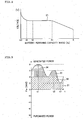
- FIG. 2 is a graph showing a correlation between a battery remaining capacity ratio (also referred to simply as the remaining capacity ratio) and a battery voltage (V) in the sodium-sulfur battery 3.
- the remaining capacity ratio indicates a ratio (%) of a dischargeable capacity (Ah) with respect to a rated capacity (Ah) of the sodium-sulfur battery. Therefore, the discharge capacity (Ah) which is an already discharged capacity is obtained by the rated capacity (Ah) x (100-the remaining capacity ratio (%).).
- a (general) characteristic of the sodium-sulfur battery is that the battery voltage (also referred to simply as the voltage) is maintained to be constant irrespective of the remaining capacity ratio in a range of approximately 40 to 90%. Moreover, when the charging proceeds and the remaining capacity ratio is approximately 95% (e.g., the discharge capacity is approximately 5% of the rated capacity), the voltage rises. Therefore, in a case where a relation between a value of the voltage and the discharge capacity at a time when the voltage rises is set beforehand, when the charging proceeds to reach the voltage, the discharge capacity control value can be corrected (reset). It is to be noted that as seen from FIG. 2 , since the voltage changes (drops) even at the end of the discharging, the discharge capacity control value can similarly be corrected (or reset) at the end of the discharging.
- the order of priority of the No. 1 sodium-sulfur battery is lowered to the last order, and the order of priority of the No. 1 to No. 4 sodium-sulfur batteries 3 is set to the order of No. 2, No. 3, No. 4 and No. 1.
- the electric power P W is assigned to the No. 1 to No. 4 sodium-sulfur batteries 3 constantly up to 2 MW at maximum in order to charge the batteries.
- the No. 2 sodium-sulfur battery 3 having a high order of priority is preferentially charged and first comes close to the end of the charging.
- the rise of the voltage can be detected to correct (reset) the discharge capacity control value of the No. 2 sodium-sulfur battery 3.
- the order of priority of the No. 2 sodium-sulfur battery is lowered to the last order. Subsequently, the order of priority may similarly be changed to repeatedly correct (reset) the discharge capacity control value of the sodium-sulfur battery 3.
- the order of priority is set to four No. 1 to No. 4 sodium-sulfur batteries, but it is important that at least one sodium-sulfur battery 3 to which the electric power P W generated by the wind power generation device 7 is to be preferentially assigned is specified among the four sodium-sulfur batteries 3.
- the discharge capacity control value can be corrected (reset).
- the order to correct (reset) the discharge capacity control value can clearly be controlled.
- the electric power P W is more assigned in accordance with the order of priority. Therefore, when the order of priority is set, the order to reach the end of the charging does not easily deviate. In these respects, it is more preferable that the order of priority is set to four No. 1 to No. 4 sodium-sulfur batteries 3 as compared with a case where the sodium-sulfur battery 3 to which the electric power P W is to be preferentially assigned is simply specified.
- a control method of a sodium-sulfur battery according to the present invention can be utilized as a method of controlling a plurality of sodium-sulfur batteries constituting a power storage compensation device in an interconnection system where natural energy such as a wind power, a sunlight or a geothermal power is used and a power generation device in which an output fluctuates is combined with the power storage compensation device to supply an electric power to a power system.
Claims (8)
- Verfahren zur Steuerung einer Vielzahl von Natrium-Schwefel-Batterien, umfassend:die Bereitstellung eines Verbindungssystems, bei dem eine Energieerzeugungsvorrichtung, in welcher das Ausgangssignal schwankt, mit einer Energiespeicherungs-Kompensationsvorrichtung kombiniert ist, um elektrische Energie in ein Energiesystem einzuspeisen, wobei die Vielzahl an Natrium-Schwefel-Batterien die Energiespeicherungs-Kompensationsvorrichtung umfasst und eine Schwankung des Ausgangssignals der Energieerzeugungsvorrichtung kompensiert,die Spezifizierung der Natrium-Schwefel-Batterie, für die ein Entladungskapazitäts-Steuerungswert unter der Vielzahl an Natrium-Schwefel-Batterien zu korrigieren oder zurückzusetzen ist;das Korrigieren oder Zurücksetzen des Entladungskapazitäts-Steuerungswerts der spezifizierten Natrium-Schwefel-Batterie; unddie nacheinander erfolgende Spezifizierung der gesamten Vielzahl an Natrium-Schwefel-Batterien um den Entladungskapazitäts-Steuerungswert wiederholt zu korrigieren oder zurückzusetzen.
- Verfahren zur Steuerung einer Natrium-Schwefel-Batterie nach Anspruch 1, worin das nahende Ende der Ladung oder Entladung detektiert wird, um den Entladungskapazitäts-Steuerungswert zu korrigieren oder zurückzusetzen.
- Verfahren zur Steuerung einer Natrium-Schwefel-Batterie nach Anspruch 2, worin das nahende Ende der Ladung oder Entladung basierend auf der Spannung der betriebenen Batterie detektiert wird.
- Verfahren zur Steuerung einer Natrium-Schwefel-Batterie nach Anspruch 3, worin das nahende Ende der Ladung für einen Fall detektiert wird, bei dem die Entladungskapazität größer als 0 % und weniger als 10 % der Nennbatteriekapazität ist und das nahende Ende der Entladung für einen Fall detektiert wird, bei dem die Entladungskapazität größer als 60 % und weniger als 100 % der Nennbatteriekapazität ist.
- Verfahren zur Steuerung einer Natrium-Schwefel-Batterie nach einem der Ansprüche 1 bis 4, worin das Ausgangssignal der Energieerzeugungsvorrichtung, in welcher das Ausgangssignal schwankt, vorzugsweise der spezifizierten Natrium-Schwefel-Batterie bis zu einem maximal zulässigen Eingangssignal zugeordnet wird, um die spezifizierte Natrium-Schwefel-Batterie zu laden.
- Verfahren zur Steuerung einer Natrium-Schwefel-Batterie nach einem der Ansprüche 1 bis 5, worin eine Rangordnung zum Korrigieren oder Zurückzusetzen des Entladungskapazitäts-Steuerungswerts für die Vielzahl an Natrium-Schwefel-Batterien zuvor eingestellt wird und die Rangordnung der Natrium-Schwefel-Batterie, in welcher der Entladungskapazitäts-Steuerungswert korrigiert oder zurückgesetzt wurde, auf den danach folgende letzten Rang heruntergesetzt wird.
- Verfahren zur Steuerung einer Natrium-Schwefel-Batterie nach Anspruch 6, worin das Ausgangssignal der Energieerzeugungsvorrichtung, in welcher das Ausgangssignal schwankt, der Natrium-Schwefel-Batterie in der Rangordnung bis zum maximal zulässigen Eingangssignal zugeordnet wird, um die Natrium-Schwefel-Batterie zu laden.
- Verfahren zur Steuerung einer Natrium-Schwefel-Batterie nach einem der Ansprüche 1 bis 7, worin die Energieerzeugungsvorrichtung, in welcher das Ausgangssignal schwankt, eine natürliche Energieerzeugungsvorrichtung ist, worin ein oder zwei oder mehr Typen von natürlichen Energiequellen ausgewählt aus der aus Windenergie, Sonnenlicht- und geothermischer Energie bestehenden Gruppe eingesetzt werden.
Priority Applications (1)
| Application Number | Priority Date | Filing Date | Title |
|---|---|---|---|
| CY20091100842T CY1110356T1 (el) | 2006-09-27 | 2009-08-07 | Μεθοδος ελεγχου μπαταριας θειικου νατριου |
Applications Claiming Priority (1)
| Application Number | Priority Date | Filing Date | Title |
|---|---|---|---|
| JP2006262667A JP5073258B2 (ja) | 2006-09-27 | 2006-09-27 | ナトリウム−硫黄電池の制御方法 |
Publications (2)
| Publication Number | Publication Date |
|---|---|
| EP1912305A1 EP1912305A1 (de) | 2008-04-16 |
| EP1912305B1 true EP1912305B1 (de) | 2009-05-27 |
Family
ID=39033656
Family Applications (1)
| Application Number | Title | Priority Date | Filing Date |
|---|---|---|---|
| EP07253756A Not-in-force EP1912305B1 (de) | 2006-09-27 | 2007-09-21 | Steuerverfahren einer Natrium-Schwefel-Batterie |
Country Status (8)
| Country | Link |
|---|---|
| US (1) | US20080076010A1 (de) |
| EP (1) | EP1912305B1 (de) |
| JP (1) | JP5073258B2 (de) |
| AT (1) | ATE432551T1 (de) |
| CY (1) | CY1110356T1 (de) |
| DE (1) | DE602007001177D1 (de) |
| DK (1) | DK1912305T3 (de) |
| ES (1) | ES2329190T3 (de) |
Families Citing this family (20)
| Publication number | Priority date | Publication date | Assignee | Title |
|---|---|---|---|---|
| JP2010051074A (ja) * | 2008-08-20 | 2010-03-04 | Ngk Insulators Ltd | ナトリウム−硫黄電池のヒータ電力供給方法 |
| EP2333894B1 (de) * | 2008-09-30 | 2014-11-05 | NGK Insulators, Ltd. | Verfahren zur steuerung einer natrium-schwefel-batterie |
| WO2010038663A1 (ja) * | 2008-09-30 | 2010-04-08 | 日本碍子株式会社 | ナトリウム-硫黄電池の制御方法 |
| WO2010038666A1 (ja) * | 2008-09-30 | 2010-04-08 | 日本碍子株式会社 | 連系システムの制御方法 |
| CN102138247B (zh) | 2008-09-30 | 2014-03-12 | 日本碍子株式会社 | 钠硫电池的控制方法 |
| CN102144328B (zh) | 2008-09-30 | 2013-11-20 | 日本碍子株式会社 | 钠硫电池的控制方法 |
| JP5599714B2 (ja) | 2008-09-30 | 2014-10-01 | 日本碍子株式会社 | 二次電池の電力制御方法 |
| JP5600066B2 (ja) * | 2008-09-30 | 2014-10-01 | 日本碍子株式会社 | ナトリウム−硫黄電池の制御方法 |
| JP5288463B2 (ja) * | 2008-10-29 | 2013-09-11 | 日本碍子株式会社 | ナトリウム−硫黄電池の充電方法 |
| EP2395595B1 (de) * | 2009-02-06 | 2014-07-23 | NGK Insulators, Ltd. | Verfahren zur bestimmung des kapazitätsabfalls einer natriumschwefelbatterie |
| JP5519665B2 (ja) | 2009-06-24 | 2014-06-11 | 日本碍子株式会社 | 電池制御装置及び電池制御方法 |
| JP5628820B2 (ja) | 2009-10-05 | 2014-11-19 | 日本碍子株式会社 | 制御装置、制御装置網及び制御方法 |
| JP5519692B2 (ja) | 2009-10-30 | 2014-06-11 | 日本碍子株式会社 | 二次電池の制御方法および電力貯蔵装置 |
| ITCS20100005A1 (it) * | 2010-02-24 | 2011-08-25 | Francesco Antonio Amoroso | Sistema e metodo per lo scambio intelligente di energia elettrica tra la rete di distribuzione elettrica ed una batteria |
| JP5533343B2 (ja) * | 2010-06-28 | 2014-06-25 | 富士通株式会社 | 電力平準化システム |
| JP5560146B2 (ja) * | 2010-09-10 | 2014-07-23 | 関西電力株式会社 | 蓄電装置制御装置 |
| EP2637277A4 (de) * | 2010-11-02 | 2017-08-09 | Panasonic Intellectual Property Management Co., Ltd. | Steuervorrichtung |
| US20120175962A1 (en) * | 2011-01-11 | 2012-07-12 | Converteam Technology Ltd. | Power Collection and Transmission Systems |
| DE102012201969A1 (de) * | 2012-02-09 | 2013-08-14 | N-ERGIE Netz GmbH | Verfahren zur Bestimmung einer maximal aufzunehmenden elektrischen Arbeit eines elektrischen Energiespeichers für ein Stromnetz |
| US20150030901A1 (en) * | 2013-07-26 | 2015-01-29 | General Electric Company | Battery heater systems and methods |
Family Cites Families (8)
| Publication number | Priority date | Publication date | Assignee | Title |
|---|---|---|---|---|
| US5686815A (en) * | 1991-02-14 | 1997-11-11 | Chartec Laboratories A/S | Method and apparatus for controlling the charging of a rechargeable battery to ensure that full charge is achieved without damaging the battery |
| US6274950B1 (en) * | 1994-03-03 | 2001-08-14 | American Power Conversion | Battery communication system |
| FR2780827B1 (fr) * | 1998-07-03 | 2000-09-29 | Electricite De France | Procede de commande d'une centrale electrique associee a une source d'energie temporellement aleatoire |
| JP2001327083A (ja) * | 2000-05-18 | 2001-11-22 | Ngk Insulators Ltd | 高温二次電池による電力貯蔵及び補償システム |
| JP2003317808A (ja) * | 2002-04-22 | 2003-11-07 | Ngk Insulators Ltd | ナトリウム−硫黄電池の充放電制御方法、並びに電力貯蔵及び補償装置 |
| JP2004147477A (ja) * | 2002-10-28 | 2004-05-20 | Komatsu Ltd | 電動機の電源装置 |
| US7239112B2 (en) * | 2004-05-10 | 2007-07-03 | International Business Machines Corporation | Battery overcharging compensation system and method |
| FR2871624B1 (fr) * | 2004-06-14 | 2006-11-17 | Commissariat Energie Atomique | Procede de gestion d'un parc de batteries rechargeables |
-
2006
- 2006-09-27 JP JP2006262667A patent/JP5073258B2/ja not_active Expired - Fee Related
-
2007
- 2007-09-18 US US11/856,787 patent/US20080076010A1/en not_active Abandoned
- 2007-09-21 AT AT07253756T patent/ATE432551T1/de not_active IP Right Cessation
- 2007-09-21 EP EP07253756A patent/EP1912305B1/de not_active Not-in-force
- 2007-09-21 ES ES07253756T patent/ES2329190T3/es active Active
- 2007-09-21 DE DE602007001177T patent/DE602007001177D1/de active Active
- 2007-09-21 DK DK07253756T patent/DK1912305T3/da active
-
2009
- 2009-08-07 CY CY20091100842T patent/CY1110356T1/el unknown
Also Published As
| Publication number | Publication date |
|---|---|
| JP5073258B2 (ja) | 2012-11-14 |
| EP1912305A1 (de) | 2008-04-16 |
| ATE432551T1 (de) | 2009-06-15 |
| CY1110356T1 (el) | 2015-04-29 |
| US20080076010A1 (en) | 2008-03-27 |
| ES2329190T3 (es) | 2009-11-23 |
| DE602007001177D1 (de) | 2009-07-09 |
| DK1912305T3 (da) | 2009-08-17 |
| JP2008084677A (ja) | 2008-04-10 |
Similar Documents
| Publication | Publication Date | Title |
|---|---|---|
| EP1912305B1 (de) | Steuerverfahren einer Natrium-Schwefel-Batterie | |
| US8080898B2 (en) | Power control method for secondary batteries | |
| JP5599714B2 (ja) | 二次電池の電力制御方法 | |
| JP5519692B2 (ja) | 二次電池の制御方法および電力貯蔵装置 | |
| JP2005312138A (ja) | 電力制御装置、発電システム及び電力系統システム | |
| US20160172864A1 (en) | Photovoltaic system | |
| KR101426826B1 (ko) | 독립형(stand-alone) 마이크로그리드를 위한 가변 저항 방식의 드룹 제어 장치 및 방법 | |
| JP2015192566A (ja) | 電力システム及び直流送電方法 | |
| US8420240B2 (en) | Method for controlling sodium-sulfur batteries | |
| EP2330677B1 (de) | Verfahren zur steuerung einer natrium-schwefel-batterie | |
| KR20170092976A (ko) | 독립형 마이크로그리드의 안정적인 운영을 위한 충전 상태 기반의 드룹 제어 방법 및 장치 | |
| JP6802694B2 (ja) | 電力供給安定化システムおよび再生エネルギ発電システム | |
| EP2333894B1 (de) | Verfahren zur steuerung einer natrium-schwefel-batterie | |
| EP2330679B1 (de) | Verfahren zur steuerung einer natrium-schwefel-batterie | |
| EP2339685B1 (de) | Verfahren zur steuerung einer natrium-schwefel-batterie | |
| US20190222028A1 (en) | System and Method for Symmetric DC Regulation for Optimized Solar Power Generation and Storage | |
| JP6055968B2 (ja) | 電源システム | |
| JP7080165B2 (ja) | 分散型電源システム | |
| JP6257425B2 (ja) | 電力供給システム | |
| KR20170002089A (ko) | 배터리 충전 시스템 및 충전 방법 | |
| JP2010108717A (ja) | ナトリウム−硫黄電池の充電方法 |
Legal Events
| Date | Code | Title | Description |
|---|---|---|---|
| PUAI | Public reference made under article 153(3) epc to a published international application that has entered the european phase |
Free format text: ORIGINAL CODE: 0009012 |
|
| AK | Designated contracting states |
Kind code of ref document: A1 Designated state(s): AT BE BG CH CY CZ DE DK EE ES FI FR GB GR HU IE IS IT LI LT LU LV MC MT NL PL PT RO SE SI SK TR |
|
| AX | Request for extension of the european patent |
Extension state: AL BA HR MK RS |
|
| 17P | Request for examination filed |
Effective date: 20080829 |
|
| GRAP | Despatch of communication of intention to grant a patent |
Free format text: ORIGINAL CODE: EPIDOSNIGR1 |
|
| AKX | Designation fees paid |
Designated state(s): AT BE BG CH CY CZ DE DK EE ES FI FR GB GR HU IE IS IT LI LT LU LV MC MT NL PL PT RO SE SI SK TR |
|
| GRAS | Grant fee paid |
Free format text: ORIGINAL CODE: EPIDOSNIGR3 |
|
| GRAA | (expected) grant |
Free format text: ORIGINAL CODE: 0009210 |
|
| AK | Designated contracting states |
Kind code of ref document: B1 Designated state(s): AT BE BG CH CY CZ DE DK EE ES FI FR GB GR HU IE IS IT LI LT LU LV MC MT NL PL PT RO SE SI SK TR |
|
| REG | Reference to a national code |
Ref country code: GB Ref legal event code: FG4D |
|
| REG | Reference to a national code |
Ref country code: CH Ref legal event code: EP |
|
| REG | Reference to a national code |
Ref country code: IE Ref legal event code: FG4D |
|
| REF | Corresponds to: |
Ref document number: 602007001177 Country of ref document: DE Date of ref document: 20090709 Kind code of ref document: P |
|
| REG | Reference to a national code |
Ref country code: DK Ref legal event code: T3 |
|
| REG | Reference to a national code |
Ref country code: GR Ref legal event code: EP Ref document number: 20090401989 Country of ref document: GR |
|
| PG25 | Lapsed in a contracting state [announced via postgrant information from national office to epo] |
Ref country code: AT Free format text: LAPSE BECAUSE OF FAILURE TO SUBMIT A TRANSLATION OF THE DESCRIPTION OR TO PAY THE FEE WITHIN THE PRESCRIBED TIME-LIMIT Effective date: 20090527 Ref country code: FI Free format text: LAPSE BECAUSE OF FAILURE TO SUBMIT A TRANSLATION OF THE DESCRIPTION OR TO PAY THE FEE WITHIN THE PRESCRIBED TIME-LIMIT Effective date: 20090527 Ref country code: PT Free format text: LAPSE BECAUSE OF FAILURE TO SUBMIT A TRANSLATION OF THE DESCRIPTION OR TO PAY THE FEE WITHIN THE PRESCRIBED TIME-LIMIT Effective date: 20090927 Ref country code: LT Free format text: LAPSE BECAUSE OF FAILURE TO SUBMIT A TRANSLATION OF THE DESCRIPTION OR TO PAY THE FEE WITHIN THE PRESCRIBED TIME-LIMIT Effective date: 20090527 |
|
| NLV1 | Nl: lapsed or annulled due to failure to fulfill the requirements of art. 29p and 29m of the patents act | ||
| REG | Reference to a national code |
Ref country code: ES Ref legal event code: FG2A Ref document number: 2329190 Country of ref document: ES Kind code of ref document: T3 |
|
| PG25 | Lapsed in a contracting state [announced via postgrant information from national office to epo] |
Ref country code: LV Free format text: LAPSE BECAUSE OF FAILURE TO SUBMIT A TRANSLATION OF THE DESCRIPTION OR TO PAY THE FEE WITHIN THE PRESCRIBED TIME-LIMIT Effective date: 20090527 Ref country code: IS Free format text: LAPSE BECAUSE OF FAILURE TO SUBMIT A TRANSLATION OF THE DESCRIPTION OR TO PAY THE FEE WITHIN THE PRESCRIBED TIME-LIMIT Effective date: 20090927 Ref country code: NL Free format text: LAPSE BECAUSE OF FAILURE TO SUBMIT A TRANSLATION OF THE DESCRIPTION OR TO PAY THE FEE WITHIN THE PRESCRIBED TIME-LIMIT Effective date: 20090527 Ref country code: PL Free format text: LAPSE BECAUSE OF FAILURE TO SUBMIT A TRANSLATION OF THE DESCRIPTION OR TO PAY THE FEE WITHIN THE PRESCRIBED TIME-LIMIT Effective date: 20090527 Ref country code: SI Free format text: LAPSE BECAUSE OF FAILURE TO SUBMIT A TRANSLATION OF THE DESCRIPTION OR TO PAY THE FEE WITHIN THE PRESCRIBED TIME-LIMIT Effective date: 20090527 Ref country code: SE Free format text: LAPSE BECAUSE OF FAILURE TO SUBMIT A TRANSLATION OF THE DESCRIPTION OR TO PAY THE FEE WITHIN THE PRESCRIBED TIME-LIMIT Effective date: 20090827 |
|
| PG25 | Lapsed in a contracting state [announced via postgrant information from national office to epo] |
Ref country code: RO Free format text: LAPSE BECAUSE OF FAILURE TO SUBMIT A TRANSLATION OF THE DESCRIPTION OR TO PAY THE FEE WITHIN THE PRESCRIBED TIME-LIMIT Effective date: 20090527 Ref country code: EE Free format text: LAPSE BECAUSE OF FAILURE TO SUBMIT A TRANSLATION OF THE DESCRIPTION OR TO PAY THE FEE WITHIN THE PRESCRIBED TIME-LIMIT Effective date: 20090527 Ref country code: CZ Free format text: LAPSE BECAUSE OF FAILURE TO SUBMIT A TRANSLATION OF THE DESCRIPTION OR TO PAY THE FEE WITHIN THE PRESCRIBED TIME-LIMIT Effective date: 20090527 |
|
| PG25 | Lapsed in a contracting state [announced via postgrant information from national office to epo] |
Ref country code: SK Free format text: LAPSE BECAUSE OF FAILURE TO SUBMIT A TRANSLATION OF THE DESCRIPTION OR TO PAY THE FEE WITHIN THE PRESCRIBED TIME-LIMIT Effective date: 20090527 Ref country code: BE Free format text: LAPSE BECAUSE OF FAILURE TO SUBMIT A TRANSLATION OF THE DESCRIPTION OR TO PAY THE FEE WITHIN THE PRESCRIBED TIME-LIMIT Effective date: 20090527 |
|
| PG25 | Lapsed in a contracting state [announced via postgrant information from national office to epo] |
Ref country code: BG Free format text: LAPSE BECAUSE OF FAILURE TO SUBMIT A TRANSLATION OF THE DESCRIPTION OR TO PAY THE FEE WITHIN THE PRESCRIBED TIME-LIMIT Effective date: 20090827 |
|
| PLBE | No opposition filed within time limit |
Free format text: ORIGINAL CODE: 0009261 |
|
| STAA | Information on the status of an ep patent application or granted ep patent |
Free format text: STATUS: NO OPPOSITION FILED WITHIN TIME LIMIT |
|
| PG25 | Lapsed in a contracting state [announced via postgrant information from national office to epo] |
Ref country code: MC Free format text: LAPSE BECAUSE OF NON-PAYMENT OF DUE FEES Effective date: 20090930 |
|
| 26N | No opposition filed |
Effective date: 20100302 |
|
| REG | Reference to a national code |
Ref country code: IE Ref legal event code: MM4A |
|
| PG25 | Lapsed in a contracting state [announced via postgrant information from national office to epo] |
Ref country code: IE Free format text: LAPSE BECAUSE OF NON-PAYMENT OF DUE FEES Effective date: 20090921 |
|
| PG25 | Lapsed in a contracting state [announced via postgrant information from national office to epo] |
Ref country code: MT Free format text: LAPSE BECAUSE OF FAILURE TO SUBMIT A TRANSLATION OF THE DESCRIPTION OR TO PAY THE FEE WITHIN THE PRESCRIBED TIME-LIMIT Effective date: 20090527 Ref country code: LU Free format text: LAPSE BECAUSE OF NON-PAYMENT OF DUE FEES Effective date: 20090921 |
|
| PG25 | Lapsed in a contracting state [announced via postgrant information from national office to epo] |
Ref country code: HU Free format text: LAPSE BECAUSE OF FAILURE TO SUBMIT A TRANSLATION OF THE DESCRIPTION OR TO PAY THE FEE WITHIN THE PRESCRIBED TIME-LIMIT Effective date: 20091128 |
|
| PG25 | Lapsed in a contracting state [announced via postgrant information from national office to epo] |
Ref country code: TR Free format text: LAPSE BECAUSE OF FAILURE TO SUBMIT A TRANSLATION OF THE DESCRIPTION OR TO PAY THE FEE WITHIN THE PRESCRIBED TIME-LIMIT Effective date: 20090527 |
|
| PGFP | Annual fee paid to national office [announced via postgrant information from national office to epo] |
Ref country code: GR Payment date: 20140814 Year of fee payment: 8 Ref country code: CH Payment date: 20140915 Year of fee payment: 8 Ref country code: DK Payment date: 20140910 Year of fee payment: 8 Ref country code: DE Payment date: 20140917 Year of fee payment: 8 Ref country code: CY Payment date: 20140808 Year of fee payment: 8 |
|
| PGFP | Annual fee paid to national office [announced via postgrant information from national office to epo] |
Ref country code: GB Payment date: 20140917 Year of fee payment: 8 Ref country code: ES Payment date: 20140812 Year of fee payment: 8 |
|
| PGFP | Annual fee paid to national office [announced via postgrant information from national office to epo] |
Ref country code: IT Payment date: 20140807 Year of fee payment: 8 |
|
| PGFP | Annual fee paid to national office [announced via postgrant information from national office to epo] |
Ref country code: FR Payment date: 20140906 Year of fee payment: 8 |
|
| REG | Reference to a national code |
Ref country code: DE Ref legal event code: R119 Ref document number: 602007001177 Country of ref document: DE |
|
| REG | Reference to a national code |
Ref country code: DK Ref legal event code: EBP Effective date: 20150930 |
|
| PG25 | Lapsed in a contracting state [announced via postgrant information from national office to epo] |
Ref country code: CY Free format text: LAPSE BECAUSE OF NON-PAYMENT OF DUE FEES Effective date: 20150921 Ref country code: IT Free format text: LAPSE BECAUSE OF NON-PAYMENT OF DUE FEES Effective date: 20150921 |
|
| REG | Reference to a national code |
Ref country code: CH Ref legal event code: PL |
|
| GBPC | Gb: european patent ceased through non-payment of renewal fee |
Effective date: 20150921 |
|
| REG | Reference to a national code |
Ref country code: GR Ref legal event code: ML Ref document number: 20090401989 Country of ref document: GR Effective date: 20160405 |
|
| REG | Reference to a national code |
Ref country code: FR Ref legal event code: ST Effective date: 20160531 |
|
| PG25 | Lapsed in a contracting state [announced via postgrant information from national office to epo] |
Ref country code: GB Free format text: LAPSE BECAUSE OF NON-PAYMENT OF DUE FEES Effective date: 20150921 Ref country code: CH Free format text: LAPSE BECAUSE OF NON-PAYMENT OF DUE FEES Effective date: 20150930 Ref country code: LI Free format text: LAPSE BECAUSE OF NON-PAYMENT OF DUE FEES Effective date: 20150930 Ref country code: DE Free format text: LAPSE BECAUSE OF NON-PAYMENT OF DUE FEES Effective date: 20160401 Ref country code: GR Free format text: LAPSE BECAUSE OF NON-PAYMENT OF DUE FEES Effective date: 20160405 |
|
| PG25 | Lapsed in a contracting state [announced via postgrant information from national office to epo] |
Ref country code: FR Free format text: LAPSE BECAUSE OF NON-PAYMENT OF DUE FEES Effective date: 20150930 |
|
| PG25 | Lapsed in a contracting state [announced via postgrant information from national office to epo] |
Ref country code: DK Free format text: LAPSE BECAUSE OF NON-PAYMENT OF DUE FEES Effective date: 20150930 |
|
| REG | Reference to a national code |
Ref country code: ES Ref legal event code: FD2A Effective date: 20161128 |
|
| PG25 | Lapsed in a contracting state [announced via postgrant information from national office to epo] |
Ref country code: ES Free format text: LAPSE BECAUSE OF NON-PAYMENT OF DUE FEES Effective date: 20150922 |