EP1910171B1 - Mécanisme de transfet rotatif - Google Patents
Mécanisme de transfet rotatif Download PDFInfo
- Publication number
- EP1910171B1 EP1910171B1 EP06755712A EP06755712A EP1910171B1 EP 1910171 B1 EP1910171 B1 EP 1910171B1 EP 06755712 A EP06755712 A EP 06755712A EP 06755712 A EP06755712 A EP 06755712A EP 1910171 B1 EP1910171 B1 EP 1910171B1
- Authority
- EP
- European Patent Office
- Prior art keywords
- conveyor
- drive shaft
- support shaft
- carton
- magazine
- Prior art date
- Legal status (The legal status is an assumption and is not a legal conclusion. Google has not performed a legal analysis and makes no representation as to the accuracy of the status listed.)
- Not-in-force
Links
- 230000007246 mechanism Effects 0.000 title claims abstract description 29
- 230000010006 flight Effects 0.000 claims abstract description 17
- 230000033001 locomotion Effects 0.000 claims abstract description 16
- 230000000694 effects Effects 0.000 claims abstract description 3
- 229910000831 Steel Inorganic materials 0.000 claims description 6
- 239000010959 steel Substances 0.000 claims description 6
- 238000000151 deposition Methods 0.000 claims description 3
- 230000009471 action Effects 0.000 claims description 2
- 238000005461 lubrication Methods 0.000 claims description 2
- 230000009467 reduction Effects 0.000 claims description 2
- 230000008901 benefit Effects 0.000 description 3
- 238000010586 diagram Methods 0.000 description 3
- 230000001133 acceleration Effects 0.000 description 1
- 238000013459 approach Methods 0.000 description 1
- 238000000429 assembly Methods 0.000 description 1
- 230000000712 assembly Effects 0.000 description 1
- 238000011109 contamination Methods 0.000 description 1
- 238000000605 extraction Methods 0.000 description 1
- 238000009432 framing Methods 0.000 description 1
- 230000003993 interaction Effects 0.000 description 1
- 210000002445 nipple Anatomy 0.000 description 1
- 239000011295 pitch Substances 0.000 description 1
Images


Classifications
-
- B—PERFORMING OPERATIONS; TRANSPORTING
- B65—CONVEYING; PACKING; STORING; HANDLING THIN OR FILAMENTARY MATERIAL
- B65B—MACHINES, APPARATUS OR DEVICES FOR, OR METHODS OF, PACKAGING ARTICLES OR MATERIALS; UNPACKING
- B65B43/00—Forming, feeding, opening or setting-up containers or receptacles in association with packaging
- B65B43/12—Feeding flexible bags or carton blanks in flat or collapsed state; Feeding flat bags connected to form a series or chain
- B65B43/14—Feeding individual bags or carton blanks from piles or magazines
- B65B43/16—Feeding individual bags or carton blanks from piles or magazines by grippers
- B65B43/18—Feeding individual bags or carton blanks from piles or magazines by grippers by suction-operated grippers
- B65B43/185—Feeding individual bags or carton blanks from piles or magazines by grippers by suction-operated grippers specially adapted for carton blanks
Definitions
- This invention relates to a rotary transfer mechanism for extracting a flat article from the discharge opening of a magazine and depositing it at a receiving station.
- EP-A-0331325 discloses a rotary mechanism according to the preamble of claim 1 and comprises a support member, a drive shaft rotatably mounted on and extending from the support member, means for rotatably driving the drive shaft, carrier means rotatable with the drive shaft, at least one support shaft rotatable on the carrier means substantially parallel to the drive shaft, whereby the support shaft can orbit round the drive shaft, means for controlling the rotational disposition of the support shaft with respect to the carrier means, at least one suction cup attached to the support shaft, means for producing a vacuum, means alternatively connecting the suction cup with the vacuum-producing means and the atmosphere, the means for controlling the support shaft including means causing the suction cup while connected with the vacuum producing means to contact an article at the discharge opening of the magazine, extract the article from the magazine, and transfer the article to the receiving station, whereupon the suction cup is connected with the atmosphere to release the article to the receiving station, characterised in that the means for controlling the at least one support shaft comprises on the one
- the suction cup "plucks" each article from the magazine, but instead of merely dropping the article at the receiving station, the suction cup imparts to the article a major component of motion in the direction of movement of the conveyor, with consequent better placement of the article on the conveyor.
- the flexibility of design in suction cup path afforded by the combination of the ratio of the rack-and-pinion drive, the disposition of the rack, and the profile of the operative extent of the cam track, allows for a wide choice of article length and disposition of magazine, whilst avoiding interference between the magazine or the conveyor with the article while it is being transferred. This is particularly important when the conveyor has flights for the timed positioning of the articles in relation to a subsequent operation, such as when the article is a sleeve carton presented on the conveyor in open condition ready for end loading with a product at a subsequent station.
- An object of the present invention is to provide a simpler and more compact rotary transfer mechanism than that of EP-A-0331325 .
- Another object is to keep the fed article path beyond the perimeter of the rotating mechanism at all times, thus enabling, in a sleeve carton feeding, erecting, and end-loading machine, product to be loaded, adjacent to fed cartons, to pass unhindered beneath the mechanism.
- a further object is to enable the mechanism to partially overhang the conveyor, thus reducing cantilevered loads and inertia of the at least one suction cup.
- Yet another object is to provide an improved path for the fed article, particularly a sleeve carton, as compared with the path afforded by the mechanism of EP-A-0331325 .
- a still further object is to provide a programmed variable motion path for the fed article, particularly of a sleeve carton with respect to its dimensions, thus giving further carton erection improvements by optimising carton erection geometry.
- a rotary transfer mechanism is provided according to claim 1.
- the carrier means needs to have a radial extent little more than the radial distance of the support shaft from the drive shaft, while the maximum radial extent of the cam track can be appreciably less, thus minimising the radial extent of the carrier means.
- opening of the cartons, ready for end loading with a product at a subsequent station along the conveyor is facilitated by arranging for the combined action of the means for rotatably driving the drive shaft and the means for controlling the at least one support shaft so that at the receiving station the at least one suction cup is moving in the same direction as the conveyor relatively at a slightly greater speed, whereby the relative movement between the suction cup, holding one side of a sleeve carton, and leading flights on the conveyor, which flights are abutted by the leading corner fold of the carton, is such as to effect an opening of the carton which is substantially completed before the carton is abutted by trailing flights on the conveyor to hold the carton in its fully open condition as it passes to and through a subsequent end-loading station.
- the drive shaft is rotatably driven by a servomotor programmed by a computer, to afford variation in the speed of the at least one suction cup along its path through the receiving station, particularly to suit different sizes of sleeve cartons.
- three support shafts are provided with two or more suction cups attached to each shaft; but two, or four or more support shafts may be provided, depending on the size of the article to be transferred and/or the spacing of articles on a conveyor; and, likewise, three or more suction cups may be attached to each support shaft, depending on the size and/or weight of article to be transferred.
- the or each pair (or more) of suction cups is preferably carried by a cantilever from a bracket secured on one end of a crank arm the other end of which is pivoted to the support shaft, and the bracket is secured to one end of a link arm the other end of which is pivoted to one end of a rocker arm the other end of which is freely rotatable on the drive shaft, whereby as the crank arm swings the suction cups are orientated accordingly, firstly for contact with an article at the discharge opening of the magazine, and secondly as required for passage through the receiving station on the conveyor.
- the cam track is preferably provided on a disc mounted inside a casing forming the carrier means along with the gear segment and cam follower, and the pinion, with the or each support shaft exiting through a sealed bearing, and with the drive shaft passing through the support member and coaxially through the casing via sealed bearings, from a gearbox and motor (e.g. a servomotor) to the rocker arm, thus effecting driving of the casing through the link arm, the crank arm and the support shaft; thus enabling the use of a steel cam plate with attendant accuracy and durability, steel gear segment and cam follower, and steel pinion, with permanent lubrication affording increased life expectation and potential noise reduction.
- a gearbox and motor e.g. a servomotor
- the rotary transfer mechanism for extracting a flat sleeve carton 20 from the discharge opening or "gate" 21 of a magazine 22 and depositing it, erected, at a receiving station 23 on a conveyor 24, comprises a support member 25, a drive shaft 26 rotatably mounted on and extending from the support member, means for rotatably driving the drive shaft consisting of a servomotor 27 programmed by a computer (not shown) and gearbox 28, carrier means 29 rotatable with the drive shaft, three support shafts 30 rotatable on the carrier means substantially parallel to the drive shaft, whereby each support shaft can orbit round the drive shaft, means 31 for controlling the rotational disposition of each support shaft with respect to the carrier means, four suction cups 32 attached to each support shaft, means (not shown) for producing a vacuum, means 33 alternately connecting the suction cups with the vacuum producing means and the atmosphere, the means 31 for controlling the support shafts including means causing the suction cups 32 while connected to the vacuum producing means to contact a carton
- the vacuum-producing means comprises two suction pumps (not shown) connected by pipelines 39, 40 to arcuate ports 41, 42 in a stationary valve plate 43 of the vacuum control means 33, a rotary valve plate 44 of which is driven with the drive shaft 26.
- the drive shaft is hollow and contains three tubes 45, one for each set of four suction cups 32 to which connection is made by means of flexible pipes 46 (indicated by broken lines only in Figure 2 for the sake of clarity) from the nearer ends of the respective tubes 45 to manifold tubes 47 cantilevered from mounting blocks 48.
- the other ends of the tubes 45 are connected by flexible pipes 49 to respective ports 50 in the rotary valve plate 44 which co-operate with the ports 41, 42 in the stationary valve plate 43, to provide vacuum at the suction cups 32, communication with the arcuate port 41 enabling a carton 20 to be plucked from the magazine 22, the feed line 39 from the respective pump to the port 41 being switched off via a solenoid valve (not shown) to avoid plucking a carton when missing product is detected.
- the arcuate port 42 enables a plucked carton to be carried into the delivery station 23 on the conveyor 24 whilst the next carton is plucked from the magazine by the next set of suction cups 32.
- a third arcuate port 51 in the stationary valve plate 43 is an exhaust port only, allowing vacuum to be 'dumped' to atmosphere, thus releasing each carton when erection is complete, and this port communicates with the atmosphere via a nipple 52 which may be provided with means to prevent ingress of contamination in very dirty atmospheres.
- Each bracket 48 is pivoted on one end of a crank arm 53 the other end of which is secured to the respective support shaft 30, and the bracket is secured to one end of a link arm 54 the other end of which is pivoted to one end of a rocker arm 55 the other end of which is freely rotatable on the drive shaft 26, whereby, as the crank arm 53 swings the respective suction cups 32 are orientated accordingly, firstly for contact with a carton blank 20 at the discharge opening 21 of the magazine 22, and, secondly, as required for passage through the receiving station 23 on the conveyor 24.
- the cam track 34 is provided on a plate 56 mounted inside a two-part casing 57, 58 forming the carrier means 29 along with the gear segments 35 and cam followers 37, and the pinions 38, with the support shafts 30 exiting through sealed bearings (not visible) from the casing port 57, and with the drive shaft 26 passing through the support member 25 and coaxially through the gearbox 28 and the two-part casing 57, 58 via bearings 59, 60 to the rocker arms 55 (each on a bearing indicated by a small x), thus effecting driving of the carrier means 29 through the link arms 54, the crank arms 53 and the support shafts 30.
- the cam plate 56 is secured to the gearbox 28 by four screws 61 and houses the bearing 59, the other bearing 60 being housed within the gearbox on a spigot 62 extending from a bevel gear 63 meshing with a bevel gear (not visible) driven by the servomotor 27.
- each set of suction cups 32 follows a curving path approaching the magazine 22 and reaches a "node point" at position E ( Figure 12 ) pushing slightly into the opening 21 of the magazine to ensure adequate contact with the foremost sleeve carton 20 for suction then to hold the nearside of the carton and pull it from the magazine as the suction cups move in a substantially straight line perpendicular to the plane of the opening 21 from the "node point" E to position H ( Figure 15 ) when the carton comes clear from the magazine.
- This substantially straight line movement of the suction cups is particularly advantageous in avoiding any slipping (or attempted slipping) between the cups and the carton as the sleeve carton is caused to open until the lower or leading corner or fold is about to be pulled free of the magazine, as shown at position G ( Figure 14 ).
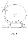
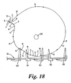
- the carton 20 then springs back towards its collapsed condition, as indicated as it passes through positions J ( Figure 16 ) and K ( Figure 17 ) to position L (see again Figure 8 ), thus thrusting its leading corner down towards the conveyor 24 through position M ( Figure 9 ) until first contacting leading flights 64 on the conveyor 24 at position N ( Figure 10 ).
- a slightly greater speed of the suction cups 32 through positions P ( Figure 11 ) and Q ( Figure 12 ) results in opening of the carton 20 again, following which the speed of the suction cups matches that of the conveyor 24 whilst passing through positions R ( Figure 13 ), S ( Figure 14 ) and T ( Figure 15 ) to press the carton into fully open position abutted by trailing flights 65 on the conveyor, as shown at position U ( Figure 16 ), at which point the suction cups are about to be connected to atmosphere (by the vacuum control means 33) to release the carton, from which the suction cups move clear, as shown at position V ( Figure 17 ).
- the support member 25 ( Figures 1 and 6 ) is plate-like and has weight-reducing cut-outs 70, 71, 72, and is mounted for limited vertical movement (for adjustment of its position to suit different sizes of cartons 20, as will be referred to again presently) by attached bearings 73 in a vertical shaft 74 upstanding from the machine base (not shown), the vertical position being set by a screw jack 75 whose screw 76 passes through a nut 77 on a bracket 78 carried by machine framing (not shown) at the top of the shaft 74.
- the support member 25 is prevented from swinging about the shaft 74 by a depending arm 79 having a roller 80 engaged in a vertical channel 81 adjacent the conveyor 24.
- Figure 1 also shows the support member 25 provided with an interchangeable plate 82 carrying an interchangeable magazine 22 of a size and with a delivery opening or "gate" 21 to suit a particular size of carton.
- the fixed continuous cam determines the locus of the path of the suction cups
- their motion is modified by the computer software programming the servomotor velocities.
- the 'overlaid' servo motion determines the speed, including acceleration and deceleration, at which the suction cups travel around the locus path, particularly through the delivery station relative to the constant velocity of the flights.
- the primary advantage arising from the 'overlaid' servo motion is to allow exactly the same rotary feeder mechanism to be used for erecting cartons of different sizes into different flight pitches.
- Complete feeder mechanism assemblies may be held in stock without need of knowledge as to what flight length they may be applied, as each flight length will have servo motion profile software dedicated to it.
- a secondary advantage afforded by the 'overlaid' servo motion is the ability to modify the motion profile of the suction cups for particular carton sizes within a given flight length machine.
- Two or more distinct predetermined motion profiles may be used to modify the position of the suction cups relative to the flights for different ranges of carton size, e.g. large, medium or small.
- a mathematical formula may be embedded within the software that will automatically modify the motion profile software responding to carton length and width dimension inputs, which can be made in various ways, e.g., at the main operator interface, such as an LED touch screen, from a menu recipe predetermined by the machine manufacturer, from a recipe input by the customer, or a combination thereof.
Claims (6)
- Mécanisme de transfert rotatif pour extraire un article (20) plat de l'ouverture d'évacuation (21) d'un magasin (22) et le déposer à un poste de réception (23) sur un transporteur (24) comprenant un élément de support (25), un arbre d'entraînement (26) monté de manière rotative sur et s'étendant à partir de l'élément de support, des moyens (27) pour entraîner en rotation de l'arbre d'entraînement, des moyens porteurs (29) rotatifs avec l'arbre d'entraînement, au moins un arbre de support (30) rotatif sur les moyens porteurs (29) essentiellement parallèles à l'arbre d'entraînement (26), moyennant quoi l'arbre de support (30) peut graviter autour de l'arbre d'entraînement (26), des moyens (31) pour commander la disposition rotative de l'arbre de support (30) par rapport aux moyens porteurs (29), au moins une ventouse (32) fixée sur l'arbre de support (30), des moyens de production d'un vide, des moyens (33) reliant en alternance la ventouse (32) aux moyens de production du vide et à l'atmosphère, les moyens (31) pour commander l'arbre de support (30) comportant des moyens faisant en sorte que la ventouse (32) tout en étant reliée aux moyens de production du vide touche un article au niveau de l'ouverture d'évacuation du magasin, extraie l'article du magasin et transfère l'article au poste de réception (23), à la suite de quoi la ventouse (32) est reliée à l'atmosphère pour libérer l'article jusqu'au poste de réception (23), caractérisé en ce que les moyens pour commander l'au moins un arbre de support (30) comprennent une piste de came (34) stationnaire continue, un segment denté (35) sur un pivot (36) sur les moyens porteurs axialement parallèle à l'arbre d'entraînement, un suiveur de came (37) sur le segment denté engagé en permanence avec la piste de came (34), et un pignon (38) fixé coaxialement à l'arbre de support (30) et s'engrenant en permanence avec le segment denté (35), le profil de la piste de came (34) étant de sorte à agir sur le segment denté (35) le long d'une partie de la piste pour faire osciller le pignon (38) afin de créer un chemin partiel de l'au moins une ventouse avec un « point nodal » au niveau de l'ouverture d'évacuation du magasin, et le long d'une autre partie de la piste afin de faire pivoter en partie le pignon (38) de sorte à faire en sorte que la ventouse (32) se déplace au-delà du poste de réception (23) dans la même direction que le transporteur (24) avec l'article généralement parallèle au transporteur (24), et en ce que l'arbre d'entraînement (26) est entraîné en rotation par un servomoteur programmé par un ordinateur, pour fournir une variation de vitesse de l'au moins une ventouse (32) le long de son chemin par le poste de réception (23), particulièrement pour s'adapter aux différentes tailles des cartons pochettes.
- Mécanisme de transfert rotatif selon la revendication 1, appliqué à une machine pour transférer des cartons pochettes plats de l'ouverture d'évacuation d'un magasin au niveau d'un poste de réception sur un transporteur (24) ayant des volées (64, 65), pour ouvrir des cartons prêts pour le chargement final avec un produit sur un poste suivant le long du transporteur, caractérisé par la disposition pour l'action combinée des moyens pour entraîner à rotation l'arbre d'entraînement (26) et des moyens pour commander l'au moins un arbre de support (30) de sorte que, au niveau du poste de réception (23), l'au moins une ventouse (32) se déplace dans la même direction que le transporteur (24) relativement à une vitesse légèrement supérieure, moyennant quoi le mouvement relatif entre la ventouse (32), maintenant un côté d'un carton pochette (20), et des volées (64, 65) avant sur le transporteur (24), lesquelles volées (64, 65) sont aboutées par le coin avant plié du carton (20), est de sorte à effectuer une ouverture du carton (20) qui est essentiellement terminée avant que le carton (20) ne soit abouté par des volées arrière (64, 65) sur le transporteur (24) pour maintenir le carton (20) dans sa condition complètement ouverte lorsqu'il passe vers et par un poste de chargement final suivant.
- Mécanisme de transfert rotatif selon la revendication 1 ou la revendication 2, caractérisé en ce que trois arbres de support (30) sont équipés de deux ou plus ventouses (32) fixées à chaque arbre.
- Mécanisme de transfert rotatif selon la revendication 3, caractérisé en ce que la ou chaque paire ou ensemble de ventouses (32) est porté(e) par un porte-à-faux d'un support (48) montée pivotante sur une extrémité d'un bras de manivelle (53), dont l'autre extrémité est pivotée vers l'arbre de support (30), et le support (48) est fixé à une extrémité d'un bras de liaison (54), dont l'autre extrémité montée pivotante sur une extrémité d'un bras oscillant (55), dont l'autre extrémité est librement rotative sur l'arbre d'entraînement (26), moyennant quoi lorsque le bras de manivelle (53) oscille, les ventouses (32) sont orientées en conséquence, premièrement pour toucher un article au niveau de l'ouverture d'évacuation du magasin, et deuxièmement comme requis, pour passer par le poste de réception sur le transporteur (24).
- Mécanisme de transfert rotatif selon l'une quelconque des revendications 1 à 4, caractérisé en ce que la piste de came (34) est prévue sur un disque à came (56) monté à l'intérieur d'un boîtier (57, 58) formant les moyens porteurs (29) avec le segment denté (35) et le suiveur de came (37), et le pignon (38), le ou chaque arbre de support (30) sortant par un palier étanche et l'arbre d'entraînement (26) passant par l'élément de support (25) et coaxialement par le boîtier (57, 58) via des paliers étanches (59, 60), d'une boîte d'engrenages (28) et d'un moteur au bras oscillant (55), effectuant ainsi l'entraînement des moyens porteurs (29) via le bras de liaison (54), le bras de manivelle (53) et l'arbre de support (30).
- Mécanisme de transfert rotatif selon l'une quelconque des revendications 1 à 5, caractérisé par un disque à came en acier (56), un segment denté (35) et un suiveur de came (37) en acier ainsi qu'un pignon en acier (38) avec une lubrification permanente permettant une augmentation de la durée de vie et une réduction potentielle du bruit.
Applications Claiming Priority (2)
| Application Number | Priority Date | Filing Date | Title |
|---|---|---|---|
| GBGB0516051.0A GB0516051D0 (en) | 2005-08-04 | 2005-08-04 | Rotary transfer mechanism |
| PCT/GB2006/002489 WO2007015049A1 (fr) | 2005-08-04 | 2006-07-05 | Mécanisme de transfet rotatif |
Publications (2)
| Publication Number | Publication Date |
|---|---|
| EP1910171A1 EP1910171A1 (fr) | 2008-04-16 |
| EP1910171B1 true EP1910171B1 (fr) | 2009-05-06 |
Family
ID=34984088
Family Applications (1)
| Application Number | Title | Priority Date | Filing Date |
|---|---|---|---|
| EP06755712A Not-in-force EP1910171B1 (fr) | 2005-08-04 | 2006-07-05 | Mécanisme de transfet rotatif |
Country Status (7)
| Country | Link |
|---|---|
| US (1) | US8047530B2 (fr) |
| EP (1) | EP1910171B1 (fr) |
| AT (1) | ATE430694T1 (fr) |
| DE (1) | DE602006006681D1 (fr) |
| ES (1) | ES2323548T3 (fr) |
| GB (1) | GB0516051D0 (fr) |
| WO (1) | WO2007015049A1 (fr) |
Cited By (1)
| Publication number | Priority date | Publication date | Assignee | Title |
|---|---|---|---|---|
| WO2014161699A1 (fr) * | 2013-04-02 | 2014-10-09 | Robert Bosch Gmbh | Système de transport d'emballages |
Families Citing this family (30)
| Publication number | Priority date | Publication date | Assignee | Title |
|---|---|---|---|---|
| US7695421B2 (en) * | 2006-02-01 | 2010-04-13 | Graphic Packaging International, Inc. | Rotary carton feeder |
| DE102007023964A1 (de) * | 2007-05-23 | 2008-11-27 | Iwk Verpackungstechnik Gmbh | Übergabevorrichtung zur Übergabe einer Faltschachtel |
| PL2098468T3 (pl) * | 2008-03-06 | 2014-07-31 | Indag Gesellschaft Fuer Ind Mbh & Co Betriebs Kg | Urządzenie do przenoszenia przedmiotów arkuszowych |
| IT1401655B1 (it) * | 2010-08-31 | 2013-08-02 | Zambelli Srl | Apparato per alimentare in continuo ad una confezionatrice anch'essa a funzionamento continuo, delle scatole od astucci impilati in configurazione tubolare e piatta. |
| IT1401817B1 (it) * | 2010-09-20 | 2013-08-28 | Baumer Srl | Sistema rotante per prelevare, trasportare ed alimentare fustellati |
| CN102139813B (zh) * | 2011-01-31 | 2013-01-23 | 杭州永创智能设备股份有限公司 | 一种纸盒坯片的吸头机构 |
| US8870519B2 (en) | 2011-09-13 | 2014-10-28 | Graphic Packaging International, Inc. | Carton feeding system |
| US20130105279A1 (en) * | 2011-10-31 | 2013-05-02 | Hernando Ramirez | System and method for independently rotating carriers |
| ITBO20120001A1 (it) * | 2012-01-03 | 2013-07-04 | Marchesini Group Spa | Unita' per il prelievo di un fustellato tubolare in configurazione appiattita e per la messa a volume dello stesso fustellato tubolare |
| EP3083417B1 (fr) * | 2013-12-20 | 2019-10-16 | Tetra Laval Holdings & Finance S.A. | Appareil d'acheminement de découpes en carton d'un magasin vers un transporteur |
| CN104369912B (zh) * | 2014-09-15 | 2016-08-17 | 中国科学院沈阳自动化研究所义乌中心 | 包装袋整存单取装置及其整存单取方法 |
| EP3265305B1 (fr) * | 2015-03-02 | 2020-09-09 | Kilklok LLC | Machine de formation de ou d'alimentation en brique alimentaire ayant un mouvement commandé |
| MX2017013718A (es) | 2015-04-29 | 2018-03-02 | Graphic Packaging Int Llc | Metodo y sistema para formar paquetes. |
| US10562675B2 (en) | 2015-04-29 | 2020-02-18 | Graphic Packaging International, Llc | Method and system for forming packages |
| CA2988665C (fr) | 2015-07-14 | 2020-06-30 | Graphic Packaging International, Inc. | Procede et systeme permettant de former des emballages |
| ITUB20154226A1 (it) * | 2015-10-08 | 2017-04-08 | Gima Spa | Stazione di prelievo e consegna di fogli sagomati definenti corpi scatolari di differente tipologia |
| CN105128404B (zh) * | 2015-10-12 | 2017-06-13 | 广东中科天工智能技术有限公司 | 一种多工位柔性装夹装置及方法 |
| IT201700036039A1 (it) * | 2017-04-03 | 2018-10-03 | Gima Spa | Stazione di prelievo e consegna |
| WO2019032436A1 (fr) | 2017-08-09 | 2019-02-14 | Graphic Packaging International, Llc | Procédé et système de formation d'emballages |
| CN107600544B (zh) * | 2017-09-30 | 2023-03-31 | 辽宁春光制药装备股份有限公司 | 装盒机高速取盒装置 |
| RU2742017C1 (ru) * | 2017-10-10 | 2021-02-01 | Бобст Гренхен Аг | Самонаклад для машины для обработки листообразного материала, как бумага, картон или пленки |
| WO2019079016A1 (fr) * | 2017-10-19 | 2019-04-25 | Westrock Packaging Systems, Llc | Dispositif de manipulation d'article pour monter des cartons |
| MX2021000248A (es) | 2018-07-09 | 2021-03-25 | Graphic Packaging Int Llc | Metodo y sistema para formar envases. |
| CA3114806C (fr) | 2018-11-06 | 2023-08-08 | Graphic Packaging International, Llc | Procede et systeme de traitement d'ebauches pour former des constructions |
| KR102003353B1 (ko) * | 2018-11-29 | 2019-07-24 | 현진제업주식회사 | 종이컵 제조를 위한 옆지 원지를 공급하는 옆지 공급 장치 |
| CN109625437B (zh) * | 2018-12-27 | 2024-01-30 | 重庆市灵龙自动化设备有限公司 | 用于塑型及定型硬质外包装的传送线 |
| MX2021008829A (es) | 2019-01-28 | 2021-09-08 | Graphic Packaging Int Llc | Empaque reforzado. |
| CN113232360A (zh) * | 2021-04-14 | 2021-08-10 | 浙江新发现机械制造有限公司 | 一种旋转吸纸机构 |
| CN113428416A (zh) * | 2021-06-29 | 2021-09-24 | 无锡西奇智能科技有限公司 | 一种内衬自动成型装置 |
| CN114290352A (zh) * | 2022-01-24 | 2022-04-08 | 惠州市超发瓦通纸品有限公司 | 一种用于印刷包装瓦楞纸的智能机器人 |
Family Cites Families (12)
| Publication number | Priority date | Publication date | Assignee | Title |
|---|---|---|---|---|
| JP2525586B2 (ja) * | 1986-12-19 | 1996-08-21 | 澁谷工業 株式会社 | カ−トン取出し装置 |
| GB8804637D0 (en) * | 1988-02-27 | 1988-03-30 | Kliklok International Ltd | Rotary transfer mechanism |
| DE4125573A1 (de) * | 1990-11-13 | 1992-05-14 | Hermann Kronseder | Vorrichtung zum ein- oder auspacken von behaeltern |
| DE4224897C1 (fr) | 1992-07-28 | 1993-06-03 | Uhlmann Pac-Systeme Gmbh & Co Kg, 7958 Laupheim, De | |
| IT1257448B (it) * | 1992-09-30 | 1996-01-25 | Apparato per l'alimentazione continua di astucci ad una cosiddetta astucciatrice | |
| US5215515A (en) | 1992-11-05 | 1993-06-01 | Boris Bershadsky | Automatic carton opening and feeding apparatus with improved breaking and supporting mechanism |
| US5431274A (en) * | 1993-06-02 | 1995-07-11 | Hms Label Specialties, Inc. | Rotary electronic profile placer |
| DE19845384B4 (de) * | 1998-10-02 | 2008-08-21 | Robert Bosch Gmbh | Vorrichtung zum Überführen flachliegender Gegenstände, insbesondere Faltschachteln |
| DE19909754A1 (de) * | 1999-03-05 | 2000-09-07 | Iwk Verpackungstechnik Gmbh | Vorrichtung zur Übergabe einer Faltschachtel |
| MXPA04002096A (es) | 2001-09-05 | 2005-07-29 | Graphic Packaging Int Inc | Tecnologia de recoleccion y colocacion giratoria. |
| DE10236069B4 (de) | 2002-08-07 | 2004-07-08 | Uhlmann Pac-Systeme Gmbh & Co Kg | Vorrichtung für die Entnahme von flach zusammengelegten Faltschachteln aus einem Magazinschacht und deren Übergabe an einen Förderer |
| US7695421B2 (en) * | 2006-02-01 | 2010-04-13 | Graphic Packaging International, Inc. | Rotary carton feeder |
-
2005
- 2005-08-04 GB GBGB0516051.0A patent/GB0516051D0/en not_active Ceased
-
2006
- 2006-07-05 EP EP06755712A patent/EP1910171B1/fr not_active Not-in-force
- 2006-07-05 US US11/997,012 patent/US8047530B2/en active Active
- 2006-07-05 DE DE602006006681T patent/DE602006006681D1/de active Active
- 2006-07-05 WO PCT/GB2006/002489 patent/WO2007015049A1/fr active Application Filing
- 2006-07-05 ES ES06755712T patent/ES2323548T3/es active Active
- 2006-07-05 AT AT06755712T patent/ATE430694T1/de not_active IP Right Cessation
Cited By (1)
| Publication number | Priority date | Publication date | Assignee | Title |
|---|---|---|---|---|
| WO2014161699A1 (fr) * | 2013-04-02 | 2014-10-09 | Robert Bosch Gmbh | Système de transport d'emballages |
Also Published As
| Publication number | Publication date |
|---|---|
| DE602006006681D1 (de) | 2009-06-18 |
| EP1910171A1 (fr) | 2008-04-16 |
| US20080227612A1 (en) | 2008-09-18 |
| ATE430694T1 (de) | 2009-05-15 |
| ES2323548T3 (es) | 2009-07-20 |
| US8047530B2 (en) | 2011-11-01 |
| WO2007015049A1 (fr) | 2007-02-08 |
| GB0516051D0 (en) | 2005-09-14 |
Similar Documents
| Publication | Publication Date | Title |
|---|---|---|
| EP1910171B1 (fr) | Mécanisme de transfet rotatif | |
| JP2794096B2 (ja) | 連続的・断続的送りインターフェイス | |
| EP0331325B1 (fr) | Mécanisme de transfert rotatif | |
| US5061231A (en) | Apparatus for erecting boxes | |
| US4596545A (en) | Orbital feeder | |
| EP0100143B1 (fr) | Magasin pour des cartons plats, des feuilles prépliées etc. | |
| US4871348A (en) | Carton erecting apparatus | |
| US5562581A (en) | Device for withdrawing and opening cases made of sheet material and for feeding them to a packaging line | |
| EP0565644A1 (fr) | Mecanisme alimentateur pour cartons en forme de boites | |
| US5613828A (en) | Handling partly completed containers | |
| JPH03620A (ja) | ブランクの連続送り方法及びその装置 | |
| US4901843A (en) | Advancing motion rotary apparatus | |
| US4605393A (en) | Carton blank removal, erection and transfer apparatus | |
| US5503519A (en) | Apparatus for loading plate-shaped articles | |
| CN112061499A (zh) | 一种基于自动包装设备的平面口罩自动包装方法 | |
| US4902192A (en) | Article control assembly for article transfer device | |
| EP1177980A2 (fr) | Machine d'emballage | |
| US7395639B2 (en) | Drive apparatus for a mail-processing system | |
| US7220094B2 (en) | Transfer device for cylindrical stacks of products arranged on an edge | |
| EP1196339B1 (fr) | Appareil de transfert rotatif dote d'une came en ligne | |
| US7441764B2 (en) | Feeder mechanism for a packaging machine | |
| JPS6214445B2 (fr) | ||
| JP2001206314A (ja) | 物品移載装置 | |
| CN210761580U (zh) | 纸箱开箱机 | |
| JP4279877B2 (ja) | パッケージング装置用の供給機構 |
Legal Events
| Date | Code | Title | Description |
|---|---|---|---|
| PUAI | Public reference made under article 153(3) epc to a published international application that has entered the european phase |
Free format text: ORIGINAL CODE: 0009012 |
|
| 17P | Request for examination filed |
Effective date: 20080110 |
|
| AK | Designated contracting states |
Kind code of ref document: A1 Designated state(s): AT BE BG CH CY CZ DE DK EE ES FI FR GB GR HU IE IS IT LI LT LU LV MC NL PL PT RO SE SI SK TR |
|
| RIN1 | Information on inventor provided before grant (corrected) |
Inventor name: HARSTON, JOHN CHRISTOPHER |
|
| GRAP | Despatch of communication of intention to grant a patent |
Free format text: ORIGINAL CODE: EPIDOSNIGR1 |
|
| GRAS | Grant fee paid |
Free format text: ORIGINAL CODE: EPIDOSNIGR3 |
|
| GRAA | (expected) grant |
Free format text: ORIGINAL CODE: 0009210 |
|
| AK | Designated contracting states |
Kind code of ref document: B1 Designated state(s): AT BE BG CH CY CZ DE DK EE ES FI FR GB GR HU IE IS IT LI LT LU LV MC NL PL PT RO SE SI SK TR |
|
| REG | Reference to a national code |
Ref country code: GB Ref legal event code: FG4D |
|
| REG | Reference to a national code |
Ref country code: CH Ref legal event code: EP |
|
| REG | Reference to a national code |
Ref country code: IE Ref legal event code: FG4D |
|
| REF | Corresponds to: |
Ref document number: 602006006681 Country of ref document: DE Date of ref document: 20090618 Kind code of ref document: P |
|
| REG | Reference to a national code |
Ref country code: ES Ref legal event code: FG2A Ref document number: 2323548 Country of ref document: ES Kind code of ref document: T3 |
|
| PG25 | Lapsed in a contracting state [announced via postgrant information from national office to epo] |
Ref country code: PT Free format text: LAPSE BECAUSE OF FAILURE TO SUBMIT A TRANSLATION OF THE DESCRIPTION OR TO PAY THE FEE WITHIN THE PRESCRIBED TIME-LIMIT Effective date: 20090906 Ref country code: LT Free format text: LAPSE BECAUSE OF FAILURE TO SUBMIT A TRANSLATION OF THE DESCRIPTION OR TO PAY THE FEE WITHIN THE PRESCRIBED TIME-LIMIT Effective date: 20090506 Ref country code: AT Free format text: LAPSE BECAUSE OF FAILURE TO SUBMIT A TRANSLATION OF THE DESCRIPTION OR TO PAY THE FEE WITHIN THE PRESCRIBED TIME-LIMIT Effective date: 20090506 Ref country code: FI Free format text: LAPSE BECAUSE OF FAILURE TO SUBMIT A TRANSLATION OF THE DESCRIPTION OR TO PAY THE FEE WITHIN THE PRESCRIBED TIME-LIMIT Effective date: 20090506 |
|
| PG25 | Lapsed in a contracting state [announced via postgrant information from national office to epo] |
Ref country code: SE Free format text: LAPSE BECAUSE OF FAILURE TO SUBMIT A TRANSLATION OF THE DESCRIPTION OR TO PAY THE FEE WITHIN THE PRESCRIBED TIME-LIMIT Effective date: 20090806 Ref country code: SI Free format text: LAPSE BECAUSE OF FAILURE TO SUBMIT A TRANSLATION OF THE DESCRIPTION OR TO PAY THE FEE WITHIN THE PRESCRIBED TIME-LIMIT Effective date: 20090506 Ref country code: IS Free format text: LAPSE BECAUSE OF FAILURE TO SUBMIT A TRANSLATION OF THE DESCRIPTION OR TO PAY THE FEE WITHIN THE PRESCRIBED TIME-LIMIT Effective date: 20090906 Ref country code: PL Free format text: LAPSE BECAUSE OF FAILURE TO SUBMIT A TRANSLATION OF THE DESCRIPTION OR TO PAY THE FEE WITHIN THE PRESCRIBED TIME-LIMIT Effective date: 20090506 Ref country code: LV Free format text: LAPSE BECAUSE OF FAILURE TO SUBMIT A TRANSLATION OF THE DESCRIPTION OR TO PAY THE FEE WITHIN THE PRESCRIBED TIME-LIMIT Effective date: 20090506 |
|
| PG25 | Lapsed in a contracting state [announced via postgrant information from national office to epo] |
Ref country code: EE Free format text: LAPSE BECAUSE OF FAILURE TO SUBMIT A TRANSLATION OF THE DESCRIPTION OR TO PAY THE FEE WITHIN THE PRESCRIBED TIME-LIMIT Effective date: 20090506 Ref country code: RO Free format text: LAPSE BECAUSE OF FAILURE TO SUBMIT A TRANSLATION OF THE DESCRIPTION OR TO PAY THE FEE WITHIN THE PRESCRIBED TIME-LIMIT Effective date: 20090506 Ref country code: DK Free format text: LAPSE BECAUSE OF FAILURE TO SUBMIT A TRANSLATION OF THE DESCRIPTION OR TO PAY THE FEE WITHIN THE PRESCRIBED TIME-LIMIT Effective date: 20090506 Ref country code: CZ Free format text: LAPSE BECAUSE OF FAILURE TO SUBMIT A TRANSLATION OF THE DESCRIPTION OR TO PAY THE FEE WITHIN THE PRESCRIBED TIME-LIMIT Effective date: 20090506 |
|
| PG25 | Lapsed in a contracting state [announced via postgrant information from national office to epo] |
Ref country code: BE Free format text: LAPSE BECAUSE OF FAILURE TO SUBMIT A TRANSLATION OF THE DESCRIPTION OR TO PAY THE FEE WITHIN THE PRESCRIBED TIME-LIMIT Effective date: 20090506 Ref country code: SK Free format text: LAPSE BECAUSE OF FAILURE TO SUBMIT A TRANSLATION OF THE DESCRIPTION OR TO PAY THE FEE WITHIN THE PRESCRIBED TIME-LIMIT Effective date: 20090506 Ref country code: MC Free format text: LAPSE BECAUSE OF NON-PAYMENT OF DUE FEES Effective date: 20090731 |
|
| PLBE | No opposition filed within time limit |
Free format text: ORIGINAL CODE: 0009261 |
|
| STAA | Information on the status of an ep patent application or granted ep patent |
Free format text: STATUS: NO OPPOSITION FILED WITHIN TIME LIMIT |
|
| PG25 | Lapsed in a contracting state [announced via postgrant information from national office to epo] |
Ref country code: BG Free format text: LAPSE BECAUSE OF FAILURE TO SUBMIT A TRANSLATION OF THE DESCRIPTION OR TO PAY THE FEE WITHIN THE PRESCRIBED TIME-LIMIT Effective date: 20090806 |
|
| 26N | No opposition filed |
Effective date: 20100209 |
|
| REG | Reference to a national code |
Ref country code: FR Ref legal event code: ST Effective date: 20100331 |
|
| REG | Reference to a national code |
Ref country code: IE Ref legal event code: MM4A |
|
| PG25 | Lapsed in a contracting state [announced via postgrant information from national office to epo] |
Ref country code: FR Free format text: LAPSE BECAUSE OF NON-PAYMENT OF DUE FEES Effective date: 20090731 |
|
| PG25 | Lapsed in a contracting state [announced via postgrant information from national office to epo] |
Ref country code: IE Free format text: LAPSE BECAUSE OF NON-PAYMENT OF DUE FEES Effective date: 20090705 |
|
| PG25 | Lapsed in a contracting state [announced via postgrant information from national office to epo] |
Ref country code: GR Free format text: LAPSE BECAUSE OF FAILURE TO SUBMIT A TRANSLATION OF THE DESCRIPTION OR TO PAY THE FEE WITHIN THE PRESCRIBED TIME-LIMIT Effective date: 20090807 |
|
| REG | Reference to a national code |
Ref country code: CH Ref legal event code: PL |
|
| PG25 | Lapsed in a contracting state [announced via postgrant information from national office to epo] |
Ref country code: CH Free format text: LAPSE BECAUSE OF NON-PAYMENT OF DUE FEES Effective date: 20100731 Ref country code: LU Free format text: LAPSE BECAUSE OF NON-PAYMENT OF DUE FEES Effective date: 20090705 Ref country code: LI Free format text: LAPSE BECAUSE OF NON-PAYMENT OF DUE FEES Effective date: 20100731 |
|
| PG25 | Lapsed in a contracting state [announced via postgrant information from national office to epo] |
Ref country code: HU Free format text: LAPSE BECAUSE OF FAILURE TO SUBMIT A TRANSLATION OF THE DESCRIPTION OR TO PAY THE FEE WITHIN THE PRESCRIBED TIME-LIMIT Effective date: 20091107 |
|
| PG25 | Lapsed in a contracting state [announced via postgrant information from national office to epo] |
Ref country code: TR Free format text: LAPSE BECAUSE OF FAILURE TO SUBMIT A TRANSLATION OF THE DESCRIPTION OR TO PAY THE FEE WITHIN THE PRESCRIBED TIME-LIMIT Effective date: 20090506 |
|
| PG25 | Lapsed in a contracting state [announced via postgrant information from national office to epo] |
Ref country code: CY Free format text: LAPSE BECAUSE OF FAILURE TO SUBMIT A TRANSLATION OF THE DESCRIPTION OR TO PAY THE FEE WITHIN THE PRESCRIBED TIME-LIMIT Effective date: 20090506 |
|
| PGFP | Annual fee paid to national office [announced via postgrant information from national office to epo] |
Ref country code: NL Payment date: 20190704 Year of fee payment: 14 |
|
| PGFP | Annual fee paid to national office [announced via postgrant information from national office to epo] |
Ref country code: IT Payment date: 20190702 Year of fee payment: 14 Ref country code: ES Payment date: 20190805 Year of fee payment: 14 |
|
| PGFP | Annual fee paid to national office [announced via postgrant information from national office to epo] |
Ref country code: GB Payment date: 20190702 Year of fee payment: 14 |
|
| REG | Reference to a national code |
Ref country code: NL Ref legal event code: MM Effective date: 20200801 |
|
| GBPC | Gb: european patent ceased through non-payment of renewal fee |
Effective date: 20200705 |
|
| PG25 | Lapsed in a contracting state [announced via postgrant information from national office to epo] |
Ref country code: NL Free format text: LAPSE BECAUSE OF NON-PAYMENT OF DUE FEES Effective date: 20200801 Ref country code: GB Free format text: LAPSE BECAUSE OF NON-PAYMENT OF DUE FEES Effective date: 20200705 |
|
| REG | Reference to a national code |
Ref country code: ES Ref legal event code: FD2A Effective date: 20211228 |
|
| PG25 | Lapsed in a contracting state [announced via postgrant information from national office to epo] |
Ref country code: ES Free format text: LAPSE BECAUSE OF NON-PAYMENT OF DUE FEES Effective date: 20200706 |
|
| PG25 | Lapsed in a contracting state [announced via postgrant information from national office to epo] |
Ref country code: IT Free format text: LAPSE BECAUSE OF NON-PAYMENT OF DUE FEES Effective date: 20200705 |
|
| PGFP | Annual fee paid to national office [announced via postgrant information from national office to epo] |
Ref country code: DE Payment date: 20220621 Year of fee payment: 17 |
|
| REG | Reference to a national code |
Ref country code: DE Ref legal event code: R119 Ref document number: 602006006681 Country of ref document: DE |