EP1909925B1 - Dispositif et procédé permettant de mesurer une force d'un coup exercée sur un appareil de jeu mobile - Google Patents
Dispositif et procédé permettant de mesurer une force d'un coup exercée sur un appareil de jeu mobile Download PDFInfo
- Publication number
- EP1909925B1 EP1909925B1 EP06776471A EP06776471A EP1909925B1 EP 1909925 B1 EP1909925 B1 EP 1909925B1 EP 06776471 A EP06776471 A EP 06776471A EP 06776471 A EP06776471 A EP 06776471A EP 1909925 B1 EP1909925 B1 EP 1909925B1
- Authority
- EP
- European Patent Office
- Prior art keywords
- shot
- ball
- force
- energy measurement
- internal pressure
- Prior art date
- Legal status (The legal status is an assumption and is not a legal conclusion. Google has not performed a legal analysis and makes no representation as to the accuracy of the status listed.)
- Not-in-force
Links
Images


Classifications
-
- G—PHYSICS
- G01—MEASURING; TESTING
- G01S—RADIO DIRECTION-FINDING; RADIO NAVIGATION; DETERMINING DISTANCE OR VELOCITY BY USE OF RADIO WAVES; LOCATING OR PRESENCE-DETECTING BY USE OF THE REFLECTION OR RERADIATION OF RADIO WAVES; ANALOGOUS ARRANGEMENTS USING OTHER WAVES
- G01S13/00—Systems using the reflection or reradiation of radio waves, e.g. radar systems; Analogous systems using reflection or reradiation of waves whose nature or wavelength is irrelevant or unspecified
- G01S13/74—Systems using reradiation of radio waves, e.g. secondary radar systems; Analogous systems
-
- A—HUMAN NECESSITIES
- A63—SPORTS; GAMES; AMUSEMENTS
- A63B—APPARATUS FOR PHYSICAL TRAINING, GYMNASTICS, SWIMMING, CLIMBING, OR FENCING; BALL GAMES; TRAINING EQUIPMENT
- A63B41/00—Hollow inflatable balls
-
- A—HUMAN NECESSITIES
- A63—SPORTS; GAMES; AMUSEMENTS
- A63B—APPARATUS FOR PHYSICAL TRAINING, GYMNASTICS, SWIMMING, CLIMBING, OR FENCING; BALL GAMES; TRAINING EQUIPMENT
- A63B43/00—Balls with special arrangements
-
- A—HUMAN NECESSITIES
- A63—SPORTS; GAMES; AMUSEMENTS
- A63B—APPARATUS FOR PHYSICAL TRAINING, GYMNASTICS, SWIMMING, CLIMBING, OR FENCING; BALL GAMES; TRAINING EQUIPMENT
- A63B71/00—Games or sports accessories not covered in groups A63B1/00 - A63B69/00
- A63B71/06—Indicating or scoring devices for games or players, or for other sports activities
- A63B71/0605—Decision makers and devices using detection means facilitating arbitration
-
- G—PHYSICS
- G01—MEASURING; TESTING
- G01S—RADIO DIRECTION-FINDING; RADIO NAVIGATION; DETERMINING DISTANCE OR VELOCITY BY USE OF RADIO WAVES; LOCATING OR PRESENCE-DETECTING BY USE OF THE REFLECTION OR RERADIATION OF RADIO WAVES; ANALOGOUS ARRANGEMENTS USING OTHER WAVES
- G01S13/00—Systems using the reflection or reradiation of radio waves, e.g. radar systems; Analogous systems using reflection or reradiation of waves whose nature or wavelength is irrelevant or unspecified
- G01S13/86—Combinations of radar systems with non-radar systems, e.g. sonar, direction finder
- G01S13/862—Combination of radar systems with sonar systems
-
- A—HUMAN NECESSITIES
- A63—SPORTS; GAMES; AMUSEMENTS
- A63B—APPARATUS FOR PHYSICAL TRAINING, GYMNASTICS, SWIMMING, CLIMBING, OR FENCING; BALL GAMES; TRAINING EQUIPMENT
- A63B2220/00—Measuring of physical parameters relating to sporting activity
- A63B2220/40—Acceleration
-
- A—HUMAN NECESSITIES
- A63—SPORTS; GAMES; AMUSEMENTS
- A63B—APPARATUS FOR PHYSICAL TRAINING, GYMNASTICS, SWIMMING, CLIMBING, OR FENCING; BALL GAMES; TRAINING EQUIPMENT
- A63B2220/00—Measuring of physical parameters relating to sporting activity
- A63B2220/80—Special sensors, transducers or devices therefor
- A63B2220/83—Special sensors, transducers or devices therefor characterised by the position of the sensor
- A63B2220/833—Sensors arranged on the exercise apparatus or sports implement
-
- A—HUMAN NECESSITIES
- A63—SPORTS; GAMES; AMUSEMENTS
- A63B—APPARATUS FOR PHYSICAL TRAINING, GYMNASTICS, SWIMMING, CLIMBING, OR FENCING; BALL GAMES; TRAINING EQUIPMENT
- A63B2225/00—Miscellaneous features of sport apparatus, devices or equipment
- A63B2225/30—Maintenance
-
- A—HUMAN NECESSITIES
- A63—SPORTS; GAMES; AMUSEMENTS
- A63B—APPARATUS FOR PHYSICAL TRAINING, GYMNASTICS, SWIMMING, CLIMBING, OR FENCING; BALL GAMES; TRAINING EQUIPMENT
- A63B2225/00—Miscellaneous features of sport apparatus, devices or equipment
- A63B2225/50—Wireless data transmission, e.g. by radio transmitters or telemetry
- A63B2225/52—Wireless data transmission, e.g. by radio transmitters or telemetry modulated by measured values
-
- A—HUMAN NECESSITIES
- A63—SPORTS; GAMES; AMUSEMENTS
- A63B—APPARATUS FOR PHYSICAL TRAINING, GYMNASTICS, SWIMMING, CLIMBING, OR FENCING; BALL GAMES; TRAINING EQUIPMENT
- A63B69/00—Training appliances or apparatus for special sports
- A63B69/002—Training appliances or apparatus for special sports for football
Definitions
- the present invention relates to mobile devices, and more particularly to gaming devices such as balls, as well as concepts for detecting contact of an object with the mobile device.
- Game equipment used in high-performance sports such as tennis balls, golf balls, footballs and the like, can now be accelerated to extremely high speeds, so that the detection of the object during the movement requires a very differentiated technology.
- the technical means hitherto used - predominantly cameras - do not meet the requirements outlined above or only insufficiently;
- the previously known methods for determining position by means of different transmitter and receiver combinations still leave a great deal of flexibility in terms of the spatial resolution of the position information, with respect to the handling of the required transmitter / receiver components and above all with regard to the evaluation of the data obtained by means of transmitter / receiver system, so that the fastest possible evaluation of the results obtained from these data is not yet possible or at least very expensive.
- a ball is known as a movable game machine having a device for measuring a shooting force applied to the movable game machine, comprising: means for providing a time course of an internal pressure of the game machine when an object impacts the game machine; means for processing the time course of the internal pressure to obtain an energy measure dependent on an energy transmitted by the shot to the object, and means for providing information about the shot power based on the energy measure.
- the ball has inside a supporting structure to which the device, in the form of a transmitting device and optionally an acceleration and / or pressure sensor is mounted.
- the transmitting device sends the signals to external antennas, whereby both the force of a shot, the acceleration of the ball and, in the event that additional external antennas are provided, and the position of the ball can be detected. It is intended to visualize the movement of the ball on a screen, preferably by a tracer track.
- the object of the present invention is to provide a flexibly applicable and yet low-effort concept for measuring a shooting force exerted on a movable game machine.
- the present invention is based on the recognition that an accurate, low-maintenance and at the same time flexibly usable firing force measurement can be achieved if a time course of an acceleration or a time course of an internal pressure of a movable game device is supplied, in order to process this time course, and although with the aim of obtaining an energy measure that depends on an energy transferred by the shot to the object. Further, there is provided means for providing information about the shooting force which uses the synergy amount for shooting force determination.
- This measure is then used according to the invention to provide firing force information.
- This shot force information can be a quantitative but unit-free value z. May be on a scale of between 1 and 10, or may be a value on an open-topped scale, or may be a value for a force applied to the movable game machine at the time of the shot or may be an energy value, ie a value for the Energy that has been introduced into the moving game device during the shot.
- the firing force may also be a length indicator that provides a measure of how far the ball would have flown, for example, if the ball had been fired at the optimum angle and without rotation.
- a Schusskrafttex is particularly interesting for ball sports, such as football or American football, since there the players intuitively more with a length measure how far z.
- a passport or tee would have gone to start, as with quantitative values or physical force or energy units.
- the unitless quantitative scale, whether closed or open is of great interest.
- a ball contact detection is also made.
- Different components can be used for both tasks.
- the use of two signals having different signal speeds is optimal for achieving a robust yet efficient and accurate detection of contact with a moving device.
- a detector in the mobile device e.g. in a football, detects whether there is an object near the football, such as the leg of a football player. This happens z. B. by a pressure, acceleration or vibration measurement or by a non-contact measurement.
- the transmitter module is driven to emit two signals that are different Have signal speeds.
- a receiver device connected to the object detects the first signal and then waits for a certain time for the reception of the second signal at a slower signal speed. If the signal is detected at a slower signal speed within the predetermined time period beginning with the reception of the first fast signal, it is assumed that the object which has received the second signal both within the first and within the predetermined time period makes contact had with the moving device. This is represented by the fact that a detector which has detected the reception of the second signal in the predetermined period of time provides a detector output signal, then stored by a memory indicating that there has been a detector output signal, thus giving (most likely) ball contact Has.
- an absolute point in time at which the detector signal has occurred can be stored in the memory so that, when thinking of a soccer game, a sequence of points in time results, which are then read out, for example, after a game or during a game depending on how many ball contacts a player had or generally said how many contacts an object with the moving device had.
- the fast signal will be detected by multiple receiver devices.
- the predetermined period of time is chosen to be highly probable, only the receiver device closest to the moving device can receive the second signal within the predetermined time period, while receiver devices further away may also receive the second signal but after Lapse of the predetermined period of time, no ball contact is registered for these players.
- the accuracy or range to be detected can be set. No access to the ball itself is required.
- the recognition of the person can not take place over periods of the radio signals.
- the incoming radio signals would have to be compared with a high-precision time reference.
- a network would have to be set up in which all measured times are compared to determine the player closest to the ball. Therefore, it is now concluded from the transmission of a radio signal and an acoustic signal who had the last ball contact.
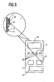
- FIG. 3 shows a schematic system sketch.
- the electronic components can also be arranged on the envelope of the ball, for example on the inside or by a suspension in the middle of the ball.
- the electronic components are connected, for example via radio 1, to a receiver 2 in order to transmit, for example, the data acquired by the electronic components. Furthermore, a microcontroller 11 is provided for processing the data. This data can then be transmitted to a data acquisition device 12. An evaluation unit 13 is provided for evaluating the acquired data, which are displayed on a display unit 14 as needed.
- the data acquisition device 12 is preferably associated with at least one player 6, but preferably all players of a game, thereby for example making a location of the nearest player, as will be explained below.
- the recognition of the person can not take place over periods of the radio signals.
- the incoming radio signals would have to be compared with a high-precision time reference and a network would have to be set up in which all measured times are compared in order to determine the player closest to the ball.
- the field strength of the transmitter on the ball could be used to estimate a distance. However, this is inaccurate.
- the evaluation unit 13 thus has means for assessing whether, within a predetermined time after receipt of the radio signal, an acoustic signal of the transmitter 4 for ball or ultrasonic waves is received.
- a device according to the invention for measuring a firing force exerted on a movable game machine is known in Fig. 9 shown.
- the apparatus comprises means 90 for providing a time course of action on the gaming device caused by a shot an acceleration or an (internal) pressure of a movable game device.
- the object that acts on the movable game machine is a tennis racket, a leg of a football player, a hand of a handball player, a table tennis bat, etc., when the movable game machine is a ball.
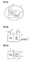
- an acceleration is applied to the movable game device, which, if it is assumed that the movable game device was previously in the idle state, equal to zero, and to a Time t 0 , at which the object impinges on the game device, will rise abruptly, then, as it is in Fig. 6a is shown to drop until the time t 1 at which the movable game device leaves the article which has acted on the movable game device.
- This drop at time t 1 can again be more or less abrupt, or the case may occur in which the acceleration curve a (t) approaches the zero value relatively "softly", at which point a constant speed is reached, which then , due to the deceleration by air friction is eventually negative.
- the deceleration of the movable game device by friction or collecting objects are initially insignificant for the Schusskrafttechnik, or to consider depending on the definition of the firing force. The latter case occurs when, for example, the shooting force is a length in meters that a football would fly. Then, the deceleration of the game device by air friction should be considered, namely in the calculation of the information about the firing force based on the Energyberger.
- the device shown has a device 92 for processing the time course of the acceleration or the time profile of the internal pressure, to obtain an energy measure that depends on an energy transferred by the shot to the object.
- This energy measure may be, for example, the speed at time t 1 exerted by the shot on the mobile game device.
- Fig. 6b Such a situation is in Fig. 6b shown. If it is again assumed that the object was at rest at time t 0 , its speed will increase due to the acceleration applied at time t 0 and increase until time t 1 . At time t 1 , for example, the football leaves the leg of the football player, and a maximum speed V max is reached, which will then decrease again due to the air friction.
- the instantaneous speed at time t between t 0 and t 1 can be easily determined by the in Fig. 6b equation shown on the right can be calculated currently.
- a preferred measure of energy is the maximum velocity at time t 1 , since this energy is the energy that the player has transferred to the gaming machine, apart from potential energy, which will typically be negligible. If the player has transferred a lot of energy, his shooting power is high. On the other hand, if the player has transmitted little energy, his firing power was low provided that other circumstances of the gaming machine, such as the internal pressure, are comparable for both cases, as it is still referring to Fig. 8 will be explained in detail.
- the device 92 can thus calculate, for example, the maximum speed as an energy measure or even, using the ball mass, calculate the energy that is associated with the maximum speed and is referred to as E max .
- the apparatus shown also includes means 94 for providing information about the firing force based on the energy measure.
- the functionality of the device 94 is based on Fig. 6e explained and can in this case, simply be an allocation table that plots the calculated energy measure in a scale, e.g. Between 1 and 10, as in the case of Fig. 6e or in an upwardly open scale or in a trend display.
- a trend indication would be that a comparison of the current energy measure with a predetermined energy measure assigned to another player; is made, so as to be able to say as a trend display so as information about the shooting power that the shooting power of the current player was greater than, equal to or less than the shooting power of the previous player.
- Such a mapping of the energy mass on a firing force information can be made with any energy measures, including z. B. when the force, as in Fig. 6c is shown as a course over time is evaluated.
- the force curve is proportional to the acceleration curve, with the mass of the movable game device as a proportionality constant.
- the course of the force over time gives an energy measure, the z. B. could be calculated by integrating the force over time.
- the force exerted on the ball directed force as a function of the locus on which the ball moves during the shot, are measured.
- the ball leaves the foot of the player at the location s 0 on the locus, so that on the ball no more driving force is exerted, but only on the air friction existing braking forces, but in Fig. 6d are not taken into account.
- An energy measure thus also represents the integration of the measured force (acceleration) over the locus, which is the
- the locus can be measured, for example, simultaneously with the acceleration sensor in the ball when the acceleration sensor is a three-dimensional acceleration sensor, which is also directionally sensitive.
- the locus of a missile can also be calculated by other means, such as high-precision satellite or ground-based positioning systems or by accessing predetermined tables.
- micromechanical locating systems using vibrating gyroscopes can also be used to determine the locus of movement in order to determine the location in Fig. 6 To be able to numerically evaluate the integral shown.
- the preferred embodiment of the present invention is to provide a pressure sensor in the movable game machine.
- the moving game device When the moving game device is shot, it could have a pressure gradient as it does in Fig. 7 is shown qualitatively.
- the article hits the movable game machine, which will cause a pressure increase in the movable game machine, because the movable game machine is deformed by the object hitting the movable game machine.
- This increase in pressure will rise to a maximum pressure p max and then decrease again in order to sink back to the steady-state pressure in the region of time t 1 , which is characterized in that the movable game device no longer has any contact with the object.
- the integral of the pressure change ie the area of the in Fig. 7 hatched area, is related to the energy exerted on the ball, so that the time course of the pressure can be advantageously used for shooting force determination.
- a pressure sensor is particularly advantageous in comparison with an acceleration sensor, since the pressure sensor is simple and, compared to an acceleration sensor, the z. B. has masses of bending beam, can be made robust. Further, it is inherent to a pressure sensor that, when located within the movable game machine, it does not output a directional quantity but a direction independent quantity, which in acceleration sensors is achieved only by elaborate provision of an acceleration sensor array which must be sensitive in three spatial directions could be. In contrast, a single pressure sensor is sufficient to provide a pressure curve of the internal pressure of the movable game device.
- a pressure sensor thus provides a maintenance-free, robust and cost-effective way to measure the pressure curve in a mobile game device, and then, as still referring to the Fig. 8 and 10 is set to obtain a shot force information.
- the pressure variation over time is integrated between t 0 and t 1 , according to the equation as shown in FIG Fig. 7 is shown. It can be seen that not the absolute pressure curve, but the course of the pressure change in comparison to the static pressure p 0 is integrated. However, the absolute pressure curve could also be integrated in order then to subtract surface 97 after integration. This results simply from the product of the duration ⁇ t and the static pressure.
- Fig. 8 Like it out Fig. 8 can be seen, the firing force depends strongly on how high the static pressure is. This is evident Fig. 8 based on the various parameter curves, wherein a parameter curve 97 is plotted for a small static pressure p 0 , while another parameter curve for a high pressure p 0 is located at 98.
- the x-axis represents the family of curves of Fig. 8
- the integrated pressure change as a measure of the energy, that is - calculated in physical units, a measure that as a unit (Pascal x seconds).
- the surface 96 of the in Fig. 7 plotted curve.
- the maximum pressure p max of the pressure curve over time by means 92 of Fig. 9 be determined.
- the course of the pressure over time ie how the shot acts on the object, is assumed to be approximately the same for all shots, such that the maximum value alone is decisive.
- a set of straight lines would be provided which are similar to the family of curves in FIG Fig. 8 is, but as x-axis would not have an integrated pressure change as a measure of energy, but the maximum pressure.
- the duration of the course of the pressure deviation which, when typical pressure curves are approximately equalized with respect to their shape, is also a measure of the energy applied to the gaming machine during the shot.
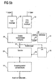
- the rest internal pressure p 0 determined in a step 100. This determination can take place either before or after the shot and is used to make one of the turns in the set of curves of Fig. 8 select.
- the pressure change is integrated in a step 102 over time, from the time t 0 to the time t 1 using the determined in a step 101 time pressure curve p (t).
- the integration over the pressure change or over the pressure deviation from the static pressure, which is performed in Fig. 102 thus provides the energy measure, which is then used to determine a value on the selected parameter curve.
- the access to a table with a set of curves takes place in a step 103 such that a three-dimensional table is provided which has triplets of values, wherein a first value of the triad is the quiescent pressure p 0 , a second value of the triad is the integrated one Pressure change is, and a third value is then the shooting force, as shown on the y-axis of Fig. 8 is applied.
- This shot force information is provided by the step 103. If Fig. 9 and Fig. 10 are compared, it can be seen that steps 100 and 101 are performed by means 90, step 102 is performed by means 92, and step 103 is performed by means 94.
- step 103 information about the type of game device can also be taken into account in step 103, which is fed in at 104.
- the firing power may depend on whether the ball is a tennis ball or a football.
- the shooting power will vary from make to make. This is particularly relevant when the "ideal range" of the ball is taken as the shooting power, which then also depends on the ball surface.
- a smoother surface of the ball has a lower air resistance, so that with the same transmitted energy, the shot power - measured in meters - will be greater than from a ball with a rougher Surface. Nevertheless, both firing results depend on the energy delivered into the ball, and in addition on the type of game machine supplied via line 104.
- Fig. 9 all or only part of the Fig. 9 be shown components in the game device itself or in a central device, which is located away from the game device.
- the ball may not necessarily have a radio sensor, but may have an output interface which, when the ball is placed in a specially designed docking station, reads out the stored traces of acceleration or pressure. Then, the processing in block 92 and the firing force information delivery in block 94 would take place in an external station such as the player's clock or a central receiving station on a football field, etc.
- both the functionality of the device 90 and the device 92 may be integrated in the ball and the ball already provides the energy measure to an external receiving station. As a result, less data has to be transferred from the ball to the outside, but more processor power is needed within the gaming device.
- all devices 90, 92, 94 may be implemented in the mobile gaming device, so that only the information about the shooting power of the ball even displayed directly is or is output via an output interface, which may be, for example, a radio interface or a contact interface.
- the system shown also includes the functionality of the external receiving interface 6 when in the ball only one sensor is present and the ball outputs the time course of acceleration or internal pressure. Then, the device 90 is to provide a time course of acceleration or internal pressure of Fig. 9 an input interface of the external computer, which additionally comprises the device 92 and the device 94.
- the inventive device for measuring the firing force can be completely arranged and implemented within the mobile gaming device or completely outside the mobile gaming device or partially within the mobile gaming device and partially outside the mobile gaming device.
- the device for measuring a shooting force exerted on a movable game device in a partial implementation comprises both the game device and the evaluation device or only the game device or only the evaluation device.
- the invention thus provides the detection of the firing force and the speed of flight of a game device 7 which can be determined from this.
- the question often arises as to who has the "hardest” shot.
- the evaluation unit 13 in the assembly 15 in the game device 7.
- a sensor can be attached, which measures the shooting force.
- This sensor is preferably a pressure sensor 10 or an acceleration sensor.
- the information from this sensor is measured by an internal microcontroller and, for example, to the display unit 14 transmitted to the data acquisition device 12 of the player.
- the determination of the shooting power requires the measurement of the energy received by the ball during the shooting.
- the evaluation unit 13 has, for example, means for detecting the pressure determined by the pressure sensor 10 over time or the acceleration detected by the acceleration sensor. Furthermore, calculating means are provided for calculating the force applied to the ball 7 by the player 6 on the basis of the pressure curve or course of the acceleration.
- the acceleration is measured directly and reported to the microcontroller in the game device 7. This calculates from the known mass of the ball and the measured acceleration, the force that has acted on the ball. These calculations include the aerodynamics and the time course of the energy supplied to the ball. In the calculation not only the total energy is transmitted to the evaluation unit 13, but also the time course of the energy transfer to the ball.
- a pressure sensor 10 it is measured how the internal pressure of the ball increases during shooting. These pressure changes and the associated timing allow the microcontroller in the ball to determine the force that has acted on the ball. With the help of the pressure measurement can be determined, how strongly the ball was deformed. The greater the deformation, the higher the shooting power. For this purpose, the peak value and the pressure profile of the internal pressure are measured with the aid of the pressure sensor 10. Based on a family of curves, the energy is determined, which was fed to the ball. For example, the family of curves can be determined empirically beforehand by means of a firing system and is different for each ball type.
- the firing force can be determined very accurately.
- For display in addition to the shooting power and the total energy can be brought. This allows information about the Winning style. So the ball can be played much more precise with a uniform energy supply. Thus, if the duration of the energy supply is displayed in addition to what additional detection means may be provided, this can also be trained.
- Based on the energy can also be closed to the airspeed that has received the ball. This takes into account the weight and aerodynamics of the ball.
- the determined airspeed is the value reached when the ball is free to fly away after the shot.
- the force information and the duration of the flight can be quite well calculated how far the ball must have flown.
- components such as at least one Hall sensor 16, at least two magnetoresistive sensors or at least two coils may be provided to determine the rotational speed of the game device 7.
- This information can be used to train so-called "banana flanks" in football. For this it is important that the user immediately receives feedback about his shot.
- the rotational speed is measured in the ball and transmitted by radio 1 to the data acquisition device 12 of the player 6.
- the components are arranged in such a way that their motion during rotation of the game device 7 in an energy field results in a modulation frequency which can be determined by the evaluation unit 13 and which can be converted into the rotational speed.
- the sensor for example the Hall sensor 16, for example, measures the earth's magnetic field and determines the field strength. If the ball rotates, the field strength undergoes a modulation. The frequency of the modulation is directly proportional to the rotational speed of the ball. When measuring the Earth's magnetic field the direction vector of the magnetic field is determined. The rotation of this vector is proportional to the ball rotation.
- the field strength can be measured with magnetoresistive sensors as magnetic field dependent resistors. These can be switched to a bridge. The output signal of the bridge can be amplified by a differential amplifier. The output voltage is a direct measure of the field strength of the magnetic field. For the purposes of the rotation measurement, neither a linearity of the voltage nor a directional determination of the field is necessary.
- the output voltage is superimposed by an alternating voltage whose frequency is the rotational frequency of the ball.
- the frequency of this AC voltage is the rotational frequency of the ball.
- the evaluation of this voltage can be done either discretely via an analog circuit or with the help of a microcontroller. In order to obtain an evaluable signal at each possible axis of rotation of the ball, two 90-degree offset sensors are used.
- the field strength can also be measured with the Hall sensor 16.
- Hall sensors generate a voltage proportional to the field strength. This voltage can be amplified by means of a differential amplifier. The output voltage is a direct measure of the field strength of the magnetic field. For the purposes of the rotation measurement, neither a linearity of the voltage nor a directional determination of the field is necessary. If the ball rotates, the output voltage is superimposed by an alternating voltage whose frequency is the rotational frequency of the ball.
- two sensors are preferably arranged offset by 90 degrees to each other.
- coils in a magnetic field can also be set in rotation, so that a voltage is induced in the coils. The frequency of the voltage is proportional to the rotation frequency. However, the voltage must be amplified and filtered because the coils can also act as antennas. Again, a discrete or a Evaluation via the microcontroller possible and preferably two coils are arranged offset 90 degrees to each other.
- radio transmitters can also be used.
- the field strength change of any radio transmitter is used, for example, a medium wave transmitter.
- the frequency of the field strength change is proportional to the rotation frequency.
- a coil or a ferrite antenna can be used in addition to a dipole. Since there are enough active long, medium and shortwave stations in each country, you do not need to operate your own stations in the system. If transmitters with a relatively high frequency are to be used as a reference, a dipole antenna can be considered which, for example, can be applied in the form of printed conductors to the bale electronics or else to the envelope of the ball.
- a frame antenna is suitable for low frequencies.
- a ferrite antenna is suitable for low frequencies. This can be made very small and yet generates a relatively large output signal. For all antennas, it is necessary to set up two directions of reception so that a signal can be measured at any axis of rotation. When measuring signals, only the field strength is important. For this purpose, an amplifier with a large dynamics is necessary. For example, the gain should be logarithmic so that the microcontroller's A / D converter does not have to be too wide.
- the data and the control of the ball electronics are handled by an extremely energy-saving microcontroller. This is awakened at the beginning of the game. If the microcontroller no longer detects a game for a long time, it switches off automatically. It is the main task of the microcontroller 11, which may also be integrated in the game device in or in addition to the microcontroller 11 in the data acquisition device to process the data so that they can be transmitted by radio 1 with as little energy as possible.
- the data is preferably transmitted several times by radio over a 2.4 GHz radio link, for example, in order to be able to correct errors.
- the power supply can be realized in a known manner in two ways.
- a battery can be used which, however, requires a charging device.
- a primary battery 21 in the data acquisition device and a primary battery 22 can be used in the game device 7, but this can not be replaced in the ball.
- a charging coil is mounted in the ball with the help of which the battery can be charged inductively.
- the ball is powered by lithium batteries.
- the capacity is designed so that over 1000 hours the function of the electronics is ensured. With an average playing time of 1 hour a day, the battery would last 3 years.
- a transceiver is integrated as a receiving unit 2. This receives the data from the ball or can connect to other data acquisition devices to exchange data. The sending and receiving of the data is e.g. in the 2.4 GHz band instead.
- the transceiver can receive and send data. This makes it possible to couple the data acquisition devices with each other. This allows the ball contacts to be transferred to the other data acquisition devices during the game, resulting in a very accurate statistical data set in the network to assess the game. Due to the data transmission, it is also possible, if necessary, to enable small computer games in which the users can play networked.
- the data in the data acquisition device 12 are processed by means of a relatively large microcontroller 11. This microcontroller is extremely energy efficient. The data is exchanged via the transceiver and visualized on a display unit 14.
- the edited data is displayed by means of a graphic display.
- the display has an integrated controller to which the microcontroller is connected. Operation is via a number of keys 20 whose function is dynamic.
- the power supply of the data acquisition device 12 must be designed very energy efficient.
- the battery 21 can be replaced.
- the microcontroller 11 and the display are extremely energy efficient.
- the data transmission is designed in such a way that the transceiver is always only in operation for a very short time.
- the ball version with battery requires a charging station. Since there is no line connection to the ball electronics, it is necessary to inductively charge the ball in a known manner.
- the charging station has a transmitting coil, with the aid of which the energy is transferred into the ball.
- the movable device 7 includes a detector 23, for example, the pressure sensor 10 of Fig. 3 which detects when the ball touches 7 becomes.
- the detector 23 may comprise a non-contact sensor operating in an electrical, acoustic, optical or electromagnetic manner and detecting, for example, whether the ball is approaching any magnetic or electric field from, for example, a corresponding transmitter in the shoe Football player is generated.
- the detector 23 is configured to detect that an object, such as a leg, a foot, a shoe, a racket, or the like is near or on the gaming machine.
- the movable device 7 includes a transmitter module 24 configured to transmit a first signal having a first signal velocity and further to a second signal having a second signal velocity less than the first signal velocity send.
- the transmitter module is configured to emit the first and second signals in response to a detector output as indicated by the signal arrow 25 in FIG Fig. 4a is shown.
- the detector 23 is a touch sensor that is configured to detect a contact of the movable device with the object.
- a touch sensor is, for example, the pressure sensor, but is also an acceleration sensor, or any other sensor that detects whether the object engages the surface of the game device 7.
- the detector may be formed as a non-contact sensor which, as has been stated, detects in some way that an object is in the vicinity of the movable device.
- a non-contact sensor capable of detecting whether an object is located at a predetermined distance equal to or smaller than 10 cm from the movable device is suitable.
- the object also touches the moving device, since it is only the target is to bring the object in contact with the movable device, for example, when thinking of a football as a movable device or a tennis ball.
- the object will finally also be in contact with the movable device.
- the transmitter module is configured to transmit two signals of different signal speeds.
- a radio signal generated by the radio transmitter 3 is used as the first fast signal.
- the second signal is generated by a sound transmitter 26, which is preferably designed as an ultrasonic transmitter.
- Both transmitters are controlled by the detector signal supplied via the line 25 so as to be responsive to the detector signal at or substantially the same time, that is, within a time period of e.g. 1 to 2 ms send both signals.
- the transmitters may be configured such that the radio transmitter transmits the first signal at a particular time determined by the detector signal 25, and that the ultrasonic transmitter then waits a predetermined period of time before the ultrasonic signal is transmitted.
- the reception of the radio transmitter would then not directly lead to the activation of a timer on the receiver side, but the timer would be activated in a predefined period of time after receiving the first signal, not immediately upon receipt of the first signal but dependent on the reception of the first signal ,
- the ball contact detection could also be used to initially emit the ultrasonic signal, then send out the radio signal after a certain period of time, which then supersaturates the ultrasonic signal, so that on the receiver side a very short predetermined period of time is sufficient, within which the radio signal and the ultrasonic signal Arrive.
- both transmitters emit their signals at the same time and that a correspondingly longer predetermined period of time is used on the receiver side or that the timer is started on the receiver side immediately upon receipt of the radio transmitter.
- the predetermined period of time depends on the difference in the speeds of the fast first signal and the slow second signal. The smaller this speed difference, the smaller the predetermined time can be selected. The greater the speed difference, the greater the predetermined time period must be set. Further, the predetermined period of time depends on whether the first and second signals are actually sent at the same time or whether the first and second signals are sent out of time, with a delay of the second signal with respect to the first signal resulting in a delay of the start of the predetermined period of time while a delay of the first signal relative to the second signal results in a smaller predetermined period of time. In general, however, predetermined time periods of less than 5 ms are preferred, as has already been stated.
- the receiver module communicates with a detector 28, which may be coupled to a memory 29, or which may be coupled to another radio transmitter within the receiver device, but which is incorporated herein by reference Fig. 5a not shown.
- Detector and memory 29 are preferably in the evaluation unit 13 of Fig. 3 contain.
- the total in Fig. 3 below receiver device or the in Fig. 5a The receiver device shown is preferably designed so that it is integrated in a wristwatch and has the shape and appearance of a wristwatch, so that it can be well worn by a football player, for example, or by a tennis player without being impaired in the performance of his sport.
- the receiver device on the object its proximity to the movable device of the detector 23 of Fig.
- Fig. 5a not shown, but for example has the form of a watch strap, a bracket for a bracelet, a clip or other fastening device that can be attached in any way to the object or to a player.
- the receiver module 2 is designed to receive the first signal at the first signal speed and the second signal at the second signal speed, which is smaller than the first signal speed. Further, the detector 28 is configured to provide a detector signal indicative of whether the second signal has been received within a predetermined time since receipt of a first signal. Further, the detector is preferably coupled to the memory 29, which is configured to store when the detector provides the detector signal. Alternatively, instead of the memory, there may also be another transmitter which is designed to send the detector signal to a central detection point, in which, for example An online evaluation of ball contacts for each player takes place.
- Such an online capture point would be, for example, a receiver located anywhere near a soccer field.
- each receiver device would output a contact with the movable device along with an identification for the player carrying the receiver device, so that undeniable statistical data can be collected on which player had how many ball contacts.
- the memory 29 may then be evaluated, for example, during the half-time break or at the end of the game or non-contact during the game without player interaction to either receive a count for each player indicating how many times the player had contact with the mobile device.
- the memory 29 would be implemented as a counter which is incremented by 1 each time the detector signal is detected.
- the memory may also detect an absolute time of a clock preferably contained in the receiver device, which in Fig. 5b drawn at 30. Then the memory would store a sequence of times that can then be evaluated to establish a "ball contact profile" over time for each player.
- contact between two players is relatively likely at the same time, for example when thinking of a "press blow".
- football for example, it is very unlikely that there will be 3 players in contact with the ball at the same time.
- a contact of two tennis rackets is already excluded at the same time, so that this additional information about typical situations in a sport with the movable game device can still be used to perform an evaluation in which errors can then be eliminated.
- Fig. 5b shows a more specific embodiment of the in Fig. 5a shown receiver.
- the receiver module comprises on the one hand a radio receiver 32 for receiving the first fast signal and an ultrasonic receiver 32 for receiving the second slower signal. Radio receivers and ultrasonic receivers may also be made differently as long as they receive any signals having different signal speeds.
- a detector 28 activates a timer 31 in response to a received radio signal via a start line 35. After elapse of a predetermined period of time, the timer is stopped, which will typically be such that the timer 31 is at the predetermined time is set, provides a stop signal via a stop line 36 to the detector.
- the detector detects an ultrasonic signal after receiving the stop signal, no detector signal is output on a line 37. Namely, in this case, it is assumed that the receiver device is far enough away from the movable device that it can be said with high probability that the movable device has not been hit. However, if an ultrasonic signal is received by the detector before receiving the stop signal, ie before the predetermined time has elapsed, then the detector signal 37 is output, which is then stored by the memory, the memory being, for example, a counter which increments by 1 by the detector signal becomes.
- the detector signal is fed to a clock, which performs an absolute time measurement, which may be, for example, an actual absolute time of day, but which, for example, is also an absolute time, which starts at the beginning of the game, for example, and thus not an absolute time plays a game minute of a football match, for example.
- the clock 30 then delivers its current state to the memory 29 via a data line 38, so that the memory can then store this time.
- an evaluation unit with interface as for example by the display unit 14th in Fig. 3 or in Fig. 5b can be implemented, which in particular with the microcontroller 11 of Fig. 3 cooperates, any evaluation of player activity can be performed.
- the methods according to the invention can be implemented in hardware or in software.
- the implementation may be on a digital storage medium, in particular a floppy disk or CD with electronically readable control signals, which may interact with a programmable computer system such that the corresponding method is executed.
- the invention thus also consists in a computer program product with program code stored on a machine-readable carrier for carrying out the method according to the invention when the computer program product runs on a computer.
- the present invention is thus also a computer program with a program code for carrying out the method for converting when the computer program runs on a computer.
Claims (13)
- Dispositif pour mesurer une force de tir exercée sur un accessoire de jeu mobile, présentant les caractéristiques suivantes :- un dispositif (90) pour fournir une courbe dans le temps, pour une pression interne de l'accessoire, qui apparaît lorsqu'on agit sur celui-ci grâce à un objet ;- un dispositif (92) pour traiter la courbe dans le temps de ladite pression interne afin d'obtenir un degré d'énergie qui dépend d'une énergie transmise à l'objet par le tir, ce dispositif de traitement (92) étant conçu pour fournir des informations sur une pression interne de repos avant ou après le tir et pour intégrer une variation de pression de la pression interne au-dessus de ladite pression interne de repos, afin d'obtenir le degré d'énergie ;- un dispositif (94) pour fournir une information sur la force de tir sur la base du degré d'énergie, avec une mémoire dans laquelle sont stockées pour différentes pressions des informations sur des courbes définies préalablement, étant précisé qu'une courbe comprend une relation entre une force de tir et un degré d'énergie, et que le dispositif (94) est conçu pour choisir une courbe sur la base de la pression interne de repos et pour fournir sur la base du degré d'énergie une force de tir qui est indiquée par la courbe sélectionnée.
- Dispositif selon la revendication 1, dans lequel le dispositif (90) comporte un capteur de pression installé sur un accessoire de jeu, ou un récepteur qui est conçu pour recevoir des courbes dans le temps provenant de l'accessoire de jeu mobile ou un degré d'énergie.
- Dispositif selon la revendication 1 ou 2, dans lequel le dispositif de traitement (92) est conçu pour intégrer dans le temps la courbe dans le temps, étant précisé qu'un résultat d'une intégration représente le degré d'énergie.
- Dispositif selon l'une des revendications précédentes, dans lequel le dispositif de traitement (92) est conçu pour examiner sur la courbe de temps un maximum, un minimum, une forme, et une durée dans le temps d'un écart par rapport à une valeur normale dans une position de repos, afin d'obtenir le degré d'énergie.
- Dispositif selon l'une des revendications précédentes, dans lequel la force de tir est une valeur sur une échelle de force de tir et dans lequel le dispositif (94) est conçu pour représenter une valeur du degré d'énergie sur une valeur de l'échelle de force de tir selon une règle de représentation prédéfinie.
- Dispositif selon l'une des revendications 1 à 4, dans lequel la force de tir dépend d'une distance sur laquelle l'accessoire de jeu mobile serait projeté si on tapait dedans suivant un angle de tir défini, et dans lequel le dispositif (94) est conçu pour calculer cette distance sur la base du degré d'énergie, d'un poids d'accessoire de jeu et d'un frottement de celui-ci dans l'air.
- Dispositif selon la revendication 1, dans lequel un tableau tridimensionnel dans lequel une force de tir est associée à différentes paires de pression interne et de degré d'énergie est stocké dans la mémoire,
et dans lequel le dispositif (94) est conçu pour avoir accès au tableau en fonction de la pression interne et du degré d'énergie, afin de déterminer la force de tir. - Dispositif selon l'une des revendications précédentes, dans lequel l'accessoire de jeu mobile est constitué par une balle.
- Dispositif selon la revendication 1, dans lequel le dispositif (94) comporte des informations sur différentes familles de courbes pour différents types d'accessoires de jeu (104), et est conçu pour identifier aussi, en plus de la pression interne et du degré d'énergie, un type d'accessoire de jeu sur la base d'une information de type d'accessoire de jeu entrée.
- Dispositif selon la revendication 9, dans lequel le dispositif (94) pour fournir une information sur la force de tir est conçu pour obtenir de l'accessoire de jeu une information de type d'accessoire de jeu par l'intermédiaire d'un signal radio.
- Accessoire de jeu mobile présentant les caractéristiques suivantes :un dispositif pour mesurer une force de tir exercée sur l'accessoire de jeu mobile, selon l'une des revendications 1 à 10.
- Procédé pour mesurer une force de tir exercée sur un accessoire de jeu mobile, comprenant les étapes suivantes :- fourniture (90) d'une courbe dans le temps, pour une pression interne de l'accessoire de jeu, qui apparaît lorsqu'on agit sur celui-ci grâce à un objet ;- traitement (92) de la courbe dans le temps de ladite pression interne afin d'obtenir un degré d'énergie qui dépend d'une énergie transmise à l'objet par le tir, cette étape de traitement comprenant la fourniture d'informations sur une pression interne de repos avant ou après le tir, et l'intégration d'une variation de pression de la pression interne au-dessus de ladite pression interne de repos, afin d'obtenir le degré d'énergie ;- fourniture (94) d'une information sur la force de tir sur la base du degré d'énergie, en utilisant une mémoire dans laquelle sont stockées pour différentes pressions internes des informations sur des courbes définies préalablement, étant précisé qu'une courbe comprend une relation entre une force de tir et un degré d'énergie, et que lors de l'étape de la fourniture (94), on choisit une courbe sur la base de la pression interne de repos, afin de fournir sur la base du degré d'énergie une force de tir qui est indiquée par la courbe sélectionnée.
- Programme informatique avec un code de programme pour la mise en oeuvre du procédé selon la revendication 12, si le programme est exécuté sur un ordinateur.
Applications Claiming Priority (2)
| Application Number | Priority Date | Filing Date | Title |
|---|---|---|---|
| DE102005036355A DE102005036355A1 (de) | 2005-07-29 | 2005-07-29 | Verfahren zur Erfassung der Kraft- und Bewegungsverhältnisse an einem Spielgerät |
| PCT/EP2006/007458 WO2007014700A1 (fr) | 2005-07-29 | 2006-07-27 | Dispositif et procede permettant de mesurer une force d'un coup exerçee sur un appareil de jeu mobile |
Publications (2)
| Publication Number | Publication Date |
|---|---|
| EP1909925A1 EP1909925A1 (fr) | 2008-04-16 |
| EP1909925B1 true EP1909925B1 (fr) | 2009-02-18 |
Family
ID=36926304
Family Applications (2)
| Application Number | Title | Priority Date | Filing Date |
|---|---|---|---|
| EP06776473A Not-in-force EP1866039B1 (fr) | 2005-07-29 | 2006-07-27 | Dispositif et procédé destinés à la mesure d'une fréquence de rotation d'un appareil de jeu mobile |
| EP06776471A Not-in-force EP1909925B1 (fr) | 2005-07-29 | 2006-07-27 | Dispositif et procédé permettant de mesurer une force d'un coup exercée sur un appareil de jeu mobile |
Family Applications Before (1)
| Application Number | Title | Priority Date | Filing Date |
|---|---|---|---|
| EP06776473A Not-in-force EP1866039B1 (fr) | 2005-07-29 | 2006-07-27 | Dispositif et procédé destinés à la mesure d'une fréquence de rotation d'un appareil de jeu mobile |
Country Status (8)
| Country | Link |
|---|---|
| US (4) | US20070059675A1 (fr) |
| EP (2) | EP1866039B1 (fr) |
| JP (2) | JP4762312B2 (fr) |
| CN (2) | CN101198382B (fr) |
| AT (2) | ATE422949T1 (fr) |
| DE (3) | DE102005036355A1 (fr) |
| ES (2) | ES2319693T3 (fr) |
| WO (3) | WO2007014700A1 (fr) |
Cited By (3)
| Publication number | Priority date | Publication date | Assignee | Title |
|---|---|---|---|---|
| US10668333B2 (en) | 2009-11-19 | 2020-06-02 | Wilson Sporting Goods Co. | Football sensing |
| US10751579B2 (en) | 2009-11-19 | 2020-08-25 | Wilson Sporting Goods Co. | Football sensing |
| US10821329B2 (en) | 2009-11-19 | 2020-11-03 | Wilson Sporting Goods Co. | Football sensing |
Families Citing this family (98)
| Publication number | Priority date | Publication date | Assignee | Title |
|---|---|---|---|---|
| US7805149B2 (en) | 2004-01-16 | 2010-09-28 | Adidas Ag | Location-aware fitness training device, methods, and program products that support real-time interactive communication and automated route generation |
| US20160345631A1 (en) | 2005-07-19 | 2016-12-01 | James Monsees | Portable devices for generating an inhalable vapor |
| DE102005036355A1 (de) * | 2005-07-29 | 2007-02-01 | Cairos Technologies Ag | Verfahren zur Erfassung der Kraft- und Bewegungsverhältnisse an einem Spielgerät |
| DE102007001820B3 (de) * | 2006-10-12 | 2008-01-24 | Cairos Technologies Ag | Konzept zur Erkennung eines Kontakts mit einem Spielgerät |
| AT504851B1 (de) * | 2006-11-07 | 2009-03-15 | Arc Seibersdorf Res Gmbh | Schlagpolster |
| EP2025372B1 (fr) * | 2007-08-15 | 2013-03-27 | Catapult Innovations Pty Ltd | Poursuit de balle dans le sport |
| US8360904B2 (en) | 2007-08-17 | 2013-01-29 | Adidas International Marketing Bv | Sports electronic training system with sport ball, and applications thereof |
| US8702430B2 (en) | 2007-08-17 | 2014-04-22 | Adidas International Marketing B.V. | Sports electronic training system, and applications thereof |
| US8221290B2 (en) | 2007-08-17 | 2012-07-17 | Adidas International Marketing B.V. | Sports electronic training system with electronic gaming features, and applications thereof |
| EP2260453A4 (fr) | 2008-02-14 | 2016-03-23 | Infomotion Sports Technologies Inc | Analyse électronique d'une performance athlétique |
| CN106021913B (zh) | 2008-03-03 | 2019-08-09 | 耐克创新有限合伙公司 | 交互式运动设备系统及方法 |
| US20090325739A1 (en) * | 2008-06-25 | 2009-12-31 | Gold Robert S | Intelligent basketball |
| DE102008057685A1 (de) * | 2008-11-17 | 2010-05-20 | Cairos Technologies Ag | Erfassen und Bereitstellen von Spielerinformationen mit Mehrfachsensorik |
| DE102008057705A1 (de) | 2008-11-17 | 2010-05-20 | Cairos Technologies Ag | Erfassen und Bereitstellen von Spielerinformationen mit spielerseitigem Sensor |
| DE102008058821B4 (de) * | 2008-11-25 | 2016-01-21 | Adidas International Marketing B.V. | Ballventil und Verfahren zur Herstellung eines Ballventils |
| US8231506B2 (en) | 2008-12-05 | 2012-07-31 | Nike, Inc. | Athletic performance monitoring systems and methods in a team sports environment |
| US8628453B2 (en) | 2008-12-05 | 2014-01-14 | Nike, Inc. | Athletic performance monitoring systems and methods in a team sports environment |
| US8172722B2 (en) | 2008-12-05 | 2012-05-08 | Nike, Inc. | Athletic performance monitoring systems and methods in a team sports environment |
| DE102008062276B3 (de) * | 2008-12-15 | 2010-09-09 | Cairos Technologies Ag | System und Verfahren zur Ballbesitzerkennung mithilfe eines passiven Feldes |
| CN104815428B (zh) | 2009-03-27 | 2018-12-25 | 罗素品牌有限责任公司 | 监测体育锻炼事件 |
| CN101898042B (zh) * | 2009-05-31 | 2012-07-18 | 鸿富锦精密工业(深圳)有限公司 | 游戏控制器及其控制方法 |
| US20120099405A1 (en) * | 2009-06-17 | 2012-04-26 | Pure Game Solutions Ltd | Sports timekeeping system |
| US20110056286A1 (en) * | 2009-09-10 | 2011-03-10 | Peter Alexander Jansen | Device and method for measuring a quantity over a spatial region |
| US9636550B2 (en) | 2009-11-19 | 2017-05-02 | Wilson Sporting Goods Co. | Football sensing |
| US8870690B2 (en) | 2009-11-19 | 2014-10-28 | Wilson Sporting Goods Co. | American-style football including electronics |
| CN102210928B (zh) * | 2010-04-06 | 2015-10-14 | 鸿富锦精密工业(深圳)有限公司 | 击打练习靶及击打式玩具 |
| EP2388048A1 (fr) * | 2010-05-19 | 2011-11-23 | Francis Chung Hwa Pan | Procédé de mesure de la trajectoire d'un mouvement de balle |
| US8622825B2 (en) * | 2010-06-22 | 2014-01-07 | Igt | Mechanically rotating wheel with changeable image |
| JP2012042299A (ja) * | 2010-08-18 | 2012-03-01 | Chung-Hua Pan | 球体移動経路の測定方法 |
| US8517870B2 (en) | 2010-09-07 | 2013-08-27 | Infomotion Sports Technologies, Inc. | Electronic component enclosure for an inflated object |
| US9298886B2 (en) | 2010-11-10 | 2016-03-29 | Nike Inc. | Consumer useable testing kit |
| EP2638491B1 (fr) | 2010-11-10 | 2022-10-05 | NIKE Innovate C.V. | Systèmes et procédés permettant de mesurer et d'afficher une activité sportive en fonction du temps |
| EP2627417A1 (fr) * | 2010-11-10 | 2013-08-21 | NIKE International Ltd. | Nécessaire d'essai utilisable par le consommateur |
| KR101767794B1 (ko) | 2011-02-17 | 2017-08-11 | 나이키 이노베이트 씨.브이. | 위치 맵핑 |
| US20120244969A1 (en) | 2011-03-25 | 2012-09-27 | May Patents Ltd. | System and Method for a Motion Sensing Device |
| US9317660B2 (en) | 2011-03-31 | 2016-04-19 | Adidas Ag | Group performance monitoring system and method |
| FR2973714A1 (fr) * | 2011-04-08 | 2012-10-12 | Thomson Licensing | Dispositif pour controler le deplacement d'un joueur virtuel et d'un ballon virtuel dans une application de jeu |
| US8944940B2 (en) | 2011-08-29 | 2015-02-03 | Icuemotion, Llc | Racket sport inertial sensor motion tracking analysis |
| DE102011116373A1 (de) | 2011-10-14 | 2013-04-18 | Dritte Patentportfolio Beteiligungsgesellschaft Mbh & Co.Kg | Methode zur Herstellung von 4-Amino-3-arylamino-6-arylpyrazolo[3, 4-d]pyrimidinen |
| US10118078B2 (en) | 2011-11-02 | 2018-11-06 | Toca Football, Inc. | System, apparatus and method for ball throwing machine and intelligent goal |
| US9010309B2 (en) * | 2011-11-02 | 2015-04-21 | Toca, Llc | Ball throwing machine and method |
| US9504414B2 (en) | 2012-04-13 | 2016-11-29 | Adidas Ag | Wearable athletic activity monitoring methods and systems |
| US9737261B2 (en) | 2012-04-13 | 2017-08-22 | Adidas Ag | Wearable athletic activity monitoring systems |
| US10922383B2 (en) | 2012-04-13 | 2021-02-16 | Adidas Ag | Athletic activity monitoring methods and systems |
| US9257054B2 (en) | 2012-04-13 | 2016-02-09 | Adidas Ag | Sport ball athletic activity monitoring methods and systems |
| US20140125806A1 (en) * | 2012-05-14 | 2014-05-08 | Sstatzz Oy | Sports Apparatus and Method |
| WO2014008134A1 (fr) | 2012-07-02 | 2014-01-09 | Infomotion Sports Technologies, Inc. | Capture mise en œuvre par ordinateur de données d'évènement sportif en direct |
| US10076685B2 (en) | 2012-07-02 | 2018-09-18 | Russell Brands, Llc | Operations with instrumented game ball |
| CN105229664B (zh) | 2012-10-25 | 2020-05-15 | 耐克创新有限合伙公司 | 团队体育环境中的运动表现监测系统和方法 |
| US10159884B2 (en) | 2012-11-09 | 2018-12-25 | Wilson Sporting Goods Co. | Basketball make-miss shot sensing |
| US9656140B2 (en) | 2012-11-09 | 2017-05-23 | Wilson Sporting Goods Co. | Sport performance system with ball sensing |
| US9901801B2 (en) | 2012-11-09 | 2018-02-27 | Wilson Sporting Goods Co. | Basketball sensing apparatus |
| US9283457B2 (en) | 2012-11-09 | 2016-03-15 | Wilson Sporting Goods Co. | Sport performance system with ball sensing |
| US9623311B2 (en) | 2012-11-09 | 2017-04-18 | Wilson Sporting Goods Co. | Basketball sensing apparatus |
| US9844704B2 (en) | 2012-11-09 | 2017-12-19 | Wilson Sporting Goods Co. | Basketball sensing apparatus |
| US10449421B2 (en) | 2012-11-09 | 2019-10-22 | Wilson Sporting Goods Co. | Basketball electronics support |
| US9656142B2 (en) | 2012-11-09 | 2017-05-23 | Wilson Sporting Goods Co. | Basketball shot determination system |
| US9656143B2 (en) | 2012-11-09 | 2017-05-23 | Wilson Sporting Goods Co. | Basketball shot determination system |
| US9500464B2 (en) | 2013-03-12 | 2016-11-22 | Adidas Ag | Methods of determining performance information for individuals and sports objects |
| US9375621B2 (en) | 2013-03-15 | 2016-06-28 | Wilson Sporting Goods, Inc. | Ball sensing |
| US9560725B2 (en) * | 2013-08-27 | 2017-01-31 | AfterDark Technologies | Illuminated sports system |
| US10076139B2 (en) | 2013-12-23 | 2018-09-18 | Juul Labs, Inc. | Vaporizer apparatus |
| USD825102S1 (en) | 2016-07-28 | 2018-08-07 | Juul Labs, Inc. | Vaporizer device with cartridge |
| FI3491948T4 (fi) | 2013-12-23 | 2024-05-06 | Juul Labs International Inc | Höyrystyslaitejärjestelmiä |
| US20160366947A1 (en) | 2013-12-23 | 2016-12-22 | James Monsees | Vaporizer apparatus |
| US10159282B2 (en) | 2013-12-23 | 2018-12-25 | Juul Labs, Inc. | Cartridge for use with a vaporizer device |
| USD842536S1 (en) | 2016-07-28 | 2019-03-05 | Juul Labs, Inc. | Vaporizer cartridge |
| US10058129B2 (en) | 2013-12-23 | 2018-08-28 | Juul Labs, Inc. | Vaporization device systems and methods |
| AU2015223149A1 (en) | 2014-02-28 | 2016-09-22 | Russell Brands, Llc | Data processing inside gaming device |
| US9849361B2 (en) | 2014-05-14 | 2017-12-26 | Adidas Ag | Sports ball athletic activity monitoring methods and systems |
| US10523053B2 (en) | 2014-05-23 | 2019-12-31 | Adidas Ag | Sport ball inductive charging methods and systems |
| US9710711B2 (en) | 2014-06-26 | 2017-07-18 | Adidas Ag | Athletic activity heads up display systems and methods |
| US9916001B2 (en) | 2014-07-08 | 2018-03-13 | Wilson Sporting Goods Co. | Sport equipment input mode control |
| US10668353B2 (en) | 2014-08-11 | 2020-06-02 | Icuemotion Llc | Codification and cueing system for sport and vocational activities |
| US10478668B2 (en) | 2014-11-24 | 2019-11-19 | Adidas Ag | Activity monitoring base station |
| EP3821735A1 (fr) | 2014-12-05 | 2021-05-19 | Juul Labs, Inc. | Commande de dose graduée |
| US11562417B2 (en) | 2014-12-22 | 2023-01-24 | Adidas Ag | Retail store motion sensor systems and methods |
| US10610101B2 (en) | 2015-07-29 | 2020-04-07 | Athalonz, Llc | Arm fatigue analysis system |
| US10854104B2 (en) | 2015-08-28 | 2020-12-01 | Icuemotion Llc | System for movement skill analysis and skill augmentation and cueing |
| CN105169631A (zh) * | 2015-09-11 | 2015-12-23 | 上海斐讯数据通信技术有限公司 | 一种俯卧撑记录系统及其应用的俯卧撑装置 |
| US9713743B1 (en) * | 2016-01-22 | 2017-07-25 | Sony Corporation | Golf swing sensor assembly |
| SG11201806801VA (en) | 2016-02-11 | 2018-09-27 | Juul Labs Inc | Securely attaching cartridges for vaporizer devices |
| US10405582B2 (en) | 2016-03-10 | 2019-09-10 | Pax Labs, Inc. | Vaporization device with lip sensing |
| NL2018235B1 (en) * | 2017-01-26 | 2018-08-01 | Innovative Golf Opportunities Llc | Virtual golf system for playing golf as well as a corresponding method. |
| USD849996S1 (en) | 2016-06-16 | 2019-05-28 | Pax Labs, Inc. | Vaporizer cartridge |
| USD836541S1 (en) | 2016-06-23 | 2018-12-25 | Pax Labs, Inc. | Charging device |
| USD851830S1 (en) | 2016-06-23 | 2019-06-18 | Pax Labs, Inc. | Combined vaporizer tamp and pick tool |
| CN107918691B (zh) * | 2016-10-07 | 2023-09-29 | 福特全球技术公司 | 用于评估信号的方法和装置 |
| WO2018136249A1 (fr) * | 2017-01-17 | 2018-07-26 | CHIP'd, Inc. | Système de suivi en temps réel pour des objets de notation de sport et procédés d'utilisation |
| USD887632S1 (en) | 2017-09-14 | 2020-06-16 | Pax Labs, Inc. | Vaporizer cartridge |
| WO2019147694A1 (fr) * | 2018-01-23 | 2019-08-01 | Company 5, Llc | Balle rebondissante dotée d'un compteur de rebonds |
| CN108196247B (zh) * | 2018-03-08 | 2023-09-12 | 北华大学 | 一种冰壶与营垒中心距离测量装置及测量方法 |
| KR102150493B1 (ko) * | 2018-04-27 | 2020-09-01 | 주식회사 골프존 | 레이더 센서 및 그 제어방법 |
| US11210554B2 (en) | 2019-03-21 | 2021-12-28 | Illumina, Inc. | Artificial intelligence-based generation of sequencing metadata |
| US11452919B2 (en) | 2019-03-27 | 2022-09-27 | Graff Golf Llc | Bluetooth enabled ball analyzer and locator |
| US10864410B2 (en) * | 2019-03-27 | 2020-12-15 | Graff Golf Llc | Bluetooth enabled ball analyzer and locator |
| CN115803816A (zh) | 2021-03-31 | 2023-03-14 | 因美纳有限公司 | 具有情境感知的基于人工智能的碱基检出器 |
| WO2023049215A1 (fr) | 2021-09-22 | 2023-03-30 | Illumina, Inc. | Appel de base basé sur l'état compressé |
Family Cites Families (49)
| Publication number | Priority date | Publication date | Assignee | Title |
|---|---|---|---|---|
| JPS6024855A (ja) * | 1983-06-16 | 1985-02-07 | 株式会社モルテン | 運動用ボ−ル |
| JPS59232562A (ja) * | 1983-06-16 | 1984-12-27 | 株式会社モルテン | 運動用ボ−ル |
| US4577865A (en) * | 1983-06-16 | 1986-03-25 | Molten Corporation | Athletic ball |
| JPS6222091A (ja) * | 1985-07-22 | 1987-01-30 | Nippon Kooteingu Kk | 距離測定方法 |
| US4940236A (en) * | 1985-07-26 | 1990-07-10 | Allen Dillis V | Computer golf club |
| US4775948A (en) * | 1987-01-08 | 1988-10-04 | Monogram Models, Inc. | Baseball having inherent speed-measuring capabilities |
| FR2667510B1 (fr) | 1990-10-09 | 1992-12-24 | Courty Claude | Dispositif destine a la pratique d'un nouveau jeu sportif individuel ou d'equipe. |
| US5150895A (en) * | 1990-11-06 | 1992-09-29 | Richard Berger | Method of and system for determining a position of ball relative to a playing field, and ball provided therefor |
| US5209483A (en) * | 1991-04-19 | 1993-05-11 | G&A Associates | Transducing and analyzing forces for instrumented sporting devices and the like |
| GB2277037B (en) * | 1992-11-19 | 1995-12-20 | David Anthony Pagani | A talking ball |
| US6241622B1 (en) * | 1998-09-18 | 2001-06-05 | Acushnet Company | Method and apparatus to determine golf ball trajectory and flight |
| US5633706A (en) * | 1993-12-27 | 1997-05-27 | Hyundai Electronics Industries Co., Ltd. | Optical distance measurement apparatus and method |
| US5586940A (en) * | 1994-11-14 | 1996-12-24 | Dosch; Thomas J. | Golf practice apparatus |
| US5526326A (en) * | 1994-12-20 | 1996-06-11 | Creata Inc. | Speed indicating ball |
| US5582550A (en) * | 1995-03-21 | 1996-12-10 | Foley; Thomas P. | Automatically-scoring mini-golf game |
| US5564698A (en) * | 1995-06-30 | 1996-10-15 | Fox Sports Productions, Inc. | Electromagnetic transmitting hockey puck |
| JPH09215808A (ja) * | 1995-12-07 | 1997-08-19 | Hokuriku Electric Ind Co Ltd | スイング型運動用具の練習装置及びスイング型運動用具 |
| US5810685A (en) * | 1996-03-07 | 1998-09-22 | Willner; Leroy Frederick | Practice ball with sound and acceleration sensor |
| GB2313193B (en) * | 1996-05-14 | 2000-06-14 | Guide Dogs For The Blind Ass T | Method and apparatus for distance measurement |
| US5779576A (en) * | 1996-08-20 | 1998-07-14 | Smith Engineering | Throw-measuring football |
| US6196932B1 (en) * | 1996-09-09 | 2001-03-06 | Donald James Marsh | Instrumented sports apparatus and feedback method |
| JPH10233146A (ja) * | 1997-02-19 | 1998-09-02 | Nec Corp | 強磁性物体通過センサ |
| US5755634A (en) * | 1997-05-19 | 1998-05-26 | Huang; Tien-Tsai | Inflatable ball with a digital pressure display |
| US6073086A (en) * | 1998-01-14 | 2000-06-06 | Silicon Pie, Inc. | Time of motion, speed, and trajectory height measuring device |
| US6148271A (en) * | 1998-01-14 | 2000-11-14 | Silicon Pie, Inc. | Speed, spin rate, and curve measuring device |
| US6151563A (en) * | 1998-01-14 | 2000-11-21 | Silicon Pie, Inc. | Speed, spin rate, and curve measuring device using magnetic field sensors |
| JP3569256B2 (ja) * | 1998-09-18 | 2004-09-22 | 日立マクセル株式会社 | 非接触通信式半導体装置 |
| US6286364B1 (en) * | 1998-09-18 | 2001-09-11 | Acushnet Company | Method and apparatus for measuring aerodynamic characteristics of a golf ball |
| US6244971B1 (en) * | 1999-01-28 | 2001-06-12 | The Distancecaddy Company, Llc | Spin determination for a rotating object |
| GB2353864A (en) * | 1999-09-06 | 2001-03-07 | Secr Defence | Pressure indicator |
| JP2001091218A (ja) * | 1999-09-14 | 2001-04-06 | Mitsubishi Electric Inf Technol Center America Inc | 3次元運動検知装置及び3次元運動検知方法 |
| GB0000105D0 (en) * | 2000-01-05 | 2000-02-23 | World Golf Systems Limited | Golf game |
| AU2001237430A1 (en) * | 2000-03-06 | 2001-09-17 | Cairos Technologies Ag | Device for detecting the position and/or movement of objects and/or living things |
| DE20004174U1 (de) * | 2000-03-06 | 2001-07-19 | Braun Hartmut | Spielgerät, Einrichtung zur Erfassung des Spielgeräts sowie Teile dieser Einrichtung |
| DE10107797A1 (de) * | 2001-02-15 | 2002-08-29 | Hielscher Frank | Spiel- und Sportgerät |
| US20020134153A1 (en) * | 2001-03-26 | 2002-09-26 | Grenlund Aaron E. | Instrumented athletic device for coaching and like purposes |
| US6582330B1 (en) * | 2001-05-04 | 2003-06-24 | Rehco, Llc | Electronic football capable of measuring throwing statistics |
| US6884180B2 (en) * | 2002-06-07 | 2005-04-26 | Brian S. Corzilius | Self-recording golf ball, golf ball cup, and reading device system |
| WO2004004396A1 (fr) | 2002-06-26 | 2004-01-08 | Nokia Corporation | Procede et element de reseau pour l'optimisation de l'utilisation de la ressource radioelectrique dans un reseau d'acces sans fil |
| GB2392246A (en) * | 2002-08-19 | 2004-02-25 | Stefan Knox | Device for measuring the speed of an object from impact pressure |
| JP4007498B2 (ja) * | 2002-11-15 | 2007-11-14 | 三菱電機株式会社 | 車載用レーダ装置 |
| TWI234641B (en) * | 2002-12-09 | 2005-06-21 | Viewmove Technologies Inc | Measurement system of detecting object distance by transmission media with different wave velocities |
| CN2609084Y (zh) * | 2002-12-27 | 2004-03-31 | 柏大同 | 一种电子监护装置 |
| DE10338620B4 (de) | 2003-08-22 | 2007-11-22 | Cairos Technologies Ag | Ballsensor |
| US20050085316A1 (en) * | 2003-10-20 | 2005-04-21 | Exelys Llc | Golf ball location system |
| DE10350300A1 (de) * | 2003-10-28 | 2005-06-02 | Helmut Staudt | In Kompartimente unterteilter Ball mit integrierten elektronischen Übertragungsmitteln |
| TWI227600B (en) * | 2003-12-15 | 2005-02-01 | Sunplus Technology Co Ltd | System for real-time detecting moving object status and the method thereof |
| US7095312B2 (en) * | 2004-05-19 | 2006-08-22 | Accurate Technologies, Inc. | System and method for tracking identity movement and location of sports objects |
| DE102005036355A1 (de) * | 2005-07-29 | 2007-02-01 | Cairos Technologies Ag | Verfahren zur Erfassung der Kraft- und Bewegungsverhältnisse an einem Spielgerät |
-
2005
- 2005-07-29 DE DE102005036355A patent/DE102005036355A1/de not_active Withdrawn
-
2006
- 2006-07-27 EP EP06776473A patent/EP1866039B1/fr not_active Not-in-force
- 2006-07-27 EP EP06776471A patent/EP1909925B1/fr not_active Not-in-force
- 2006-07-27 US US11/460,573 patent/US20070059675A1/en not_active Abandoned
- 2006-07-27 CN CN2006800217661A patent/CN101198382B/zh not_active Expired - Fee Related
- 2006-07-27 JP JP2008523247A patent/JP4762312B2/ja not_active Expired - Fee Related
- 2006-07-27 US US11/460,562 patent/US20070060425A1/en not_active Abandoned
- 2006-07-27 JP JP2008523249A patent/JP4773519B2/ja not_active Expired - Fee Related
- 2006-07-27 WO PCT/EP2006/007458 patent/WO2007014700A1/fr active Application Filing
- 2006-07-27 DE DE502006002656T patent/DE502006002656D1/de active Active
- 2006-07-27 ES ES06776473T patent/ES2319693T3/es active Active
- 2006-07-27 AT AT06776471T patent/ATE422949T1/de not_active IP Right Cessation
- 2006-07-27 US US11/460,565 patent/US7891666B2/en not_active Expired - Fee Related
- 2006-07-27 AT AT06776473T patent/ATE420703T1/de not_active IP Right Cessation
- 2006-07-27 ES ES06776471T patent/ES2321339T3/es active Active
- 2006-07-27 CN CN2006800278966A patent/CN101232923B/zh not_active Expired - Fee Related
- 2006-07-27 WO PCT/EP2006/007460 patent/WO2007014701A1/fr active Application Filing
- 2006-07-27 WO PCT/EP2006/007461 patent/WO2007014702A1/fr active Application Filing
- 2006-07-27 DE DE502006002898T patent/DE502006002898D1/de active Active
-
2011
- 2011-01-20 US US13/010,180 patent/US20110119022A1/en not_active Abandoned
Cited By (3)
| Publication number | Priority date | Publication date | Assignee | Title |
|---|---|---|---|---|
| US10668333B2 (en) | 2009-11-19 | 2020-06-02 | Wilson Sporting Goods Co. | Football sensing |
| US10751579B2 (en) | 2009-11-19 | 2020-08-25 | Wilson Sporting Goods Co. | Football sensing |
| US10821329B2 (en) | 2009-11-19 | 2020-11-03 | Wilson Sporting Goods Co. | Football sensing |
Also Published As
| Publication number | Publication date |
|---|---|
| JP4762312B2 (ja) | 2011-08-31 |
| ES2319693T3 (es) | 2009-05-11 |
| DE102005036355A1 (de) | 2007-02-01 |
| WO2007014702A1 (fr) | 2007-02-08 |
| JP2009503468A (ja) | 2009-01-29 |
| WO2007014700A1 (fr) | 2007-02-08 |
| CN101232923B (zh) | 2011-10-19 |
| JP4773519B2 (ja) | 2011-09-14 |
| CN101232923A (zh) | 2008-07-30 |
| US20070059675A1 (en) | 2007-03-15 |
| DE502006002898D1 (de) | 2009-04-02 |
| US20070060425A1 (en) | 2007-03-15 |
| ES2321339T3 (es) | 2009-06-04 |
| JP2009503466A (ja) | 2009-01-29 |
| US20070191083A1 (en) | 2007-08-16 |
| ATE422949T1 (de) | 2009-03-15 |
| US20110119022A1 (en) | 2011-05-19 |
| WO2007014701A1 (fr) | 2007-02-08 |
| ATE420703T1 (de) | 2009-01-15 |
| EP1866039A1 (fr) | 2007-12-19 |
| CN101198382B (zh) | 2011-01-05 |
| DE502006002656D1 (de) | 2009-03-05 |
| CN101198382A (zh) | 2008-06-11 |
| US7891666B2 (en) | 2011-02-22 |
| EP1909925A1 (fr) | 2008-04-16 |
| EP1866039B1 (fr) | 2009-01-14 |
Similar Documents
| Publication | Publication Date | Title |
|---|---|---|
| EP1909925B1 (fr) | Dispositif et procédé permettant de mesurer une force d'un coup exercée sur un appareil de jeu mobile | |
| EP1984082B1 (fr) | Concept relatif à la détection d'un contact avec un article de jeu | |
| EP2200723B1 (fr) | Détection et mise à disposition d'informations sur les joueurs, au moyen d'un capteur porté par le joueur | |
| EP2758804B1 (fr) | Système et procédé pour détecter un état dépendant de l'utilisateur d'un article de sport | |
| EP2366121B1 (fr) | Système et procédé de reconnaissance de détention de balle à l'aide d'une génération de champ passif | |
| DE102008057685A1 (de) | Erfassen und Bereitstellen von Spielerinformationen mit Mehrfachsensorik | |
| CH705403A1 (de) | Vorrichtung zur Erfassung von Tennis-Spieldaten. | |
| WO2005094949A1 (fr) | Capteur de position et procede d'analyse de mouvement | |
| DE10338620B4 (de) | Ballsensor | |
| WO2001066201A1 (fr) | Dispositif pour detecter la position et/ou les mouvements d'objets et/ou d'etres vivants | |
| DE102006008333B4 (de) | Vorrichtung und Verfahren zum Training der Bewegung eines Schlägers zum Schlagen eines Balles, insbesondere für das Golfspiel, für Baseball, für Tennis und für Eishockey | |
| DE10029459A1 (de) | Einrichtung zur Erfassung der Position und/oder Bewegung eines Objekts und/oder Lebewesens sowie Teile dieser Einrichtung | |
| WO2009146914A1 (fr) | Système et procédé d'analyse automatisée du déroulement d'une compétition | |
| WO2021003502A1 (fr) | Dispositif de surveillance d'entraînement | |
| DE10362202B4 (de) | Ballsensor | |
| DE10116974B4 (de) | Gerätesystem für Kegel- und Bowling-Spieler | |
| DE102006005558A1 (de) | Ballsport-Trainingssystem | |
| DE10143588A1 (de) | Golfball mit integrierter GPS-Empfangseinheit | |
| DE102014118148A1 (de) | Anordnung und Verfahren zur elektronischen Erfassung und Verarbeitung von Schlägersportart-bezogenen Daten | |
| EP3976214A1 (fr) | Tête de club de golf et club de golf |
Legal Events
| Date | Code | Title | Description |
|---|---|---|---|
| PUAI | Public reference made under article 153(3) epc to a published international application that has entered the european phase |
Free format text: ORIGINAL CODE: 0009012 |
|
| 17P | Request for examination filed |
Effective date: 20080108 |
|
| AK | Designated contracting states |
Kind code of ref document: A1 Designated state(s): AT BE BG CH CY CZ DE DK EE ES FI FR GB GR HU IE IS IT LI LT LU LV MC NL PL PT RO SE SI SK TR |
|
| 17Q | First examination report despatched |
Effective date: 20080519 |
|
| RTI1 | Title (correction) |
Free format text: DEVICE AND METHOD FOR MEASURING THE FORCE OF A SHOT TO WHICH A MOVABLE GAMING DEVICE IS SUBJECTED |
|
| GRAP | Despatch of communication of intention to grant a patent |
Free format text: ORIGINAL CODE: EPIDOSNIGR1 |
|
| GRAS | Grant fee paid |
Free format text: ORIGINAL CODE: EPIDOSNIGR3 |
|
| GRAA | (expected) grant |
Free format text: ORIGINAL CODE: 0009210 |
|
| AK | Designated contracting states |
Kind code of ref document: B1 Designated state(s): AT BE BG CH CY CZ DE DK EE ES FI FR GB GR HU IE IS IT LI LT LU LV MC NL PL PT RO SE SI SK TR |
|
| REG | Reference to a national code |
Ref country code: GB Ref legal event code: FG4D Free format text: NOT ENGLISH |
|
| REG | Reference to a national code |
Ref country code: CH Ref legal event code: EP |
|
| REG | Reference to a national code |
Ref country code: IE Ref legal event code: FG4D Free format text: LANGUAGE OF EP DOCUMENT: GERMAN |
|
| REF | Corresponds to: |
Ref document number: 502006002898 Country of ref document: DE Date of ref document: 20090402 Kind code of ref document: P |
|
| REG | Reference to a national code |
Ref country code: ES Ref legal event code: FG2A Ref document number: 2321339 Country of ref document: ES Kind code of ref document: T3 |
|
| PG25 | Lapsed in a contracting state [announced via postgrant information from national office to epo] |
Ref country code: FI Free format text: LAPSE BECAUSE OF FAILURE TO SUBMIT A TRANSLATION OF THE DESCRIPTION OR TO PAY THE FEE WITHIN THE PRESCRIBED TIME-LIMIT Effective date: 20090218 Ref country code: LT Free format text: LAPSE BECAUSE OF FAILURE TO SUBMIT A TRANSLATION OF THE DESCRIPTION OR TO PAY THE FEE WITHIN THE PRESCRIBED TIME-LIMIT Effective date: 20090218 Ref country code: NL Free format text: LAPSE BECAUSE OF FAILURE TO SUBMIT A TRANSLATION OF THE DESCRIPTION OR TO PAY THE FEE WITHIN THE PRESCRIBED TIME-LIMIT Effective date: 20090218 Ref country code: SI Free format text: LAPSE BECAUSE OF FAILURE TO SUBMIT A TRANSLATION OF THE DESCRIPTION OR TO PAY THE FEE WITHIN THE PRESCRIBED TIME-LIMIT Effective date: 20090218 |
|
| NLV1 | Nl: lapsed or annulled due to failure to fulfill the requirements of art. 29p and 29m of the patents act | ||
| PG25 | Lapsed in a contracting state [announced via postgrant information from national office to epo] |
Ref country code: SE Free format text: LAPSE BECAUSE OF FAILURE TO SUBMIT A TRANSLATION OF THE DESCRIPTION OR TO PAY THE FEE WITHIN THE PRESCRIBED TIME-LIMIT Effective date: 20090518 Ref country code: LV Free format text: LAPSE BECAUSE OF FAILURE TO SUBMIT A TRANSLATION OF THE DESCRIPTION OR TO PAY THE FEE WITHIN THE PRESCRIBED TIME-LIMIT Effective date: 20090218 Ref country code: IS Free format text: LAPSE BECAUSE OF FAILURE TO SUBMIT A TRANSLATION OF THE DESCRIPTION OR TO PAY THE FEE WITHIN THE PRESCRIBED TIME-LIMIT Effective date: 20090618 Ref country code: PL Free format text: LAPSE BECAUSE OF FAILURE TO SUBMIT A TRANSLATION OF THE DESCRIPTION OR TO PAY THE FEE WITHIN THE PRESCRIBED TIME-LIMIT Effective date: 20090218 |
|
| REG | Reference to a national code |
Ref country code: IE Ref legal event code: FD4D |
|
| PG25 | Lapsed in a contracting state [announced via postgrant information from national office to epo] |
Ref country code: IE Free format text: LAPSE BECAUSE OF FAILURE TO SUBMIT A TRANSLATION OF THE DESCRIPTION OR TO PAY THE FEE WITHIN THE PRESCRIBED TIME-LIMIT Effective date: 20090218 Ref country code: PT Free format text: LAPSE BECAUSE OF FAILURE TO SUBMIT A TRANSLATION OF THE DESCRIPTION OR TO PAY THE FEE WITHIN THE PRESCRIBED TIME-LIMIT Effective date: 20090727 Ref country code: CZ Free format text: LAPSE BECAUSE OF FAILURE TO SUBMIT A TRANSLATION OF THE DESCRIPTION OR TO PAY THE FEE WITHIN THE PRESCRIBED TIME-LIMIT Effective date: 20090218 Ref country code: DK Free format text: LAPSE BECAUSE OF FAILURE TO SUBMIT A TRANSLATION OF THE DESCRIPTION OR TO PAY THE FEE WITHIN THE PRESCRIBED TIME-LIMIT Effective date: 20090218 Ref country code: EE Free format text: LAPSE BECAUSE OF FAILURE TO SUBMIT A TRANSLATION OF THE DESCRIPTION OR TO PAY THE FEE WITHIN THE PRESCRIBED TIME-LIMIT Effective date: 20090218 |
|
| PG25 | Lapsed in a contracting state [announced via postgrant information from national office to epo] |
Ref country code: RO Free format text: LAPSE BECAUSE OF FAILURE TO SUBMIT A TRANSLATION OF THE DESCRIPTION OR TO PAY THE FEE WITHIN THE PRESCRIBED TIME-LIMIT Effective date: 20090218 Ref country code: SK Free format text: LAPSE BECAUSE OF FAILURE TO SUBMIT A TRANSLATION OF THE DESCRIPTION OR TO PAY THE FEE WITHIN THE PRESCRIBED TIME-LIMIT Effective date: 20090218 |
|
| PLBE | No opposition filed within time limit |
Free format text: ORIGINAL CODE: 0009261 |
|
| STAA | Information on the status of an ep patent application or granted ep patent |
Free format text: STATUS: NO OPPOSITION FILED WITHIN TIME LIMIT |
|
| 26N | No opposition filed |
Effective date: 20091119 |
|
| PG25 | Lapsed in a contracting state [announced via postgrant information from national office to epo] |
Ref country code: BG Free format text: LAPSE BECAUSE OF FAILURE TO SUBMIT A TRANSLATION OF THE DESCRIPTION OR TO PAY THE FEE WITHIN THE PRESCRIBED TIME-LIMIT Effective date: 20090518 |
|
| BERE | Be: lapsed |
Owner name: CAIROS TECHNOLOGIES A.G. Effective date: 20090731 |
|
| PG25 | Lapsed in a contracting state [announced via postgrant information from national office to epo] |
Ref country code: MC Free format text: LAPSE BECAUSE OF NON-PAYMENT OF DUE FEES Effective date: 20090731 |
|
| PG25 | Lapsed in a contracting state [announced via postgrant information from national office to epo] |
Ref country code: BE Free format text: LAPSE BECAUSE OF NON-PAYMENT OF DUE FEES Effective date: 20090731 |
|
| PG25 | Lapsed in a contracting state [announced via postgrant information from national office to epo] |
Ref country code: GR Free format text: LAPSE BECAUSE OF FAILURE TO SUBMIT A TRANSLATION OF THE DESCRIPTION OR TO PAY THE FEE WITHIN THE PRESCRIBED TIME-LIMIT Effective date: 20090519 |
|
| PG25 | Lapsed in a contracting state [announced via postgrant information from national office to epo] |
Ref country code: AT Free format text: LAPSE BECAUSE OF NON-PAYMENT OF DUE FEES Effective date: 20090727 |
|
| REG | Reference to a national code |
Ref country code: CH Ref legal event code: PL |
|
| PG25 | Lapsed in a contracting state [announced via postgrant information from national office to epo] |
Ref country code: LI Free format text: LAPSE BECAUSE OF NON-PAYMENT OF DUE FEES Effective date: 20100731 Ref country code: LU Free format text: LAPSE BECAUSE OF NON-PAYMENT OF DUE FEES Effective date: 20090727 Ref country code: CH Free format text: LAPSE BECAUSE OF NON-PAYMENT OF DUE FEES Effective date: 20100731 |
|
| PG25 | Lapsed in a contracting state [announced via postgrant information from national office to epo] |
Ref country code: HU Free format text: LAPSE BECAUSE OF FAILURE TO SUBMIT A TRANSLATION OF THE DESCRIPTION OR TO PAY THE FEE WITHIN THE PRESCRIBED TIME-LIMIT Effective date: 20090819 |
|
| PG25 | Lapsed in a contracting state [announced via postgrant information from national office to epo] |
Ref country code: TR Free format text: LAPSE BECAUSE OF FAILURE TO SUBMIT A TRANSLATION OF THE DESCRIPTION OR TO PAY THE FEE WITHIN THE PRESCRIBED TIME-LIMIT Effective date: 20090218 |
|
| PG25 | Lapsed in a contracting state [announced via postgrant information from national office to epo] |
Ref country code: CY Free format text: LAPSE BECAUSE OF FAILURE TO SUBMIT A TRANSLATION OF THE DESCRIPTION OR TO PAY THE FEE WITHIN THE PRESCRIBED TIME-LIMIT Effective date: 20090218 |
|
| PGFP | Annual fee paid to national office [announced via postgrant information from national office to epo] |
Ref country code: DE Payment date: 20130730 Year of fee payment: 8 Ref country code: ES Payment date: 20130704 Year of fee payment: 8 |
|
| PGFP | Annual fee paid to national office [announced via postgrant information from national office to epo] |
Ref country code: GB Payment date: 20130724 Year of fee payment: 8 Ref country code: FR Payment date: 20130719 Year of fee payment: 8 |
|
| PGFP | Annual fee paid to national office [announced via postgrant information from national office to epo] |
Ref country code: IT Payment date: 20130723 Year of fee payment: 8 |
|
| REG | Reference to a national code |
Ref country code: DE Ref legal event code: R119 Ref document number: 502006002898 Country of ref document: DE |
|
| GBPC | Gb: european patent ceased through non-payment of renewal fee |
Effective date: 20140727 |
|
| REG | Reference to a national code |
Ref country code: FR Ref legal event code: ST Effective date: 20150331 |
|
| PG25 | Lapsed in a contracting state [announced via postgrant information from national office to epo] |
Ref country code: IT Free format text: LAPSE BECAUSE OF NON-PAYMENT OF DUE FEES Effective date: 20140727 Ref country code: DE Free format text: LAPSE BECAUSE OF NON-PAYMENT OF DUE FEES Effective date: 20150203 |
|
| REG | Reference to a national code |
Ref country code: DE Ref legal event code: R119 Ref document number: 502006002898 Country of ref document: DE Effective date: 20150203 |
|
| PG25 | Lapsed in a contracting state [announced via postgrant information from national office to epo] |
Ref country code: FR Free format text: LAPSE BECAUSE OF NON-PAYMENT OF DUE FEES Effective date: 20140731 Ref country code: GB Free format text: LAPSE BECAUSE OF NON-PAYMENT OF DUE FEES Effective date: 20140727 |
|
| REG | Reference to a national code |
Ref country code: ES Ref legal event code: FD2A Effective date: 20150826 |
|
| PG25 | Lapsed in a contracting state [announced via postgrant information from national office to epo] |
Ref country code: ES Free format text: LAPSE BECAUSE OF NON-PAYMENT OF DUE FEES Effective date: 20140728 |