EP1909344B1 - Battery pack, and assembly of battery pack and motor-driven tool or charger - Google Patents
Battery pack, and assembly of battery pack and motor-driven tool or charger Download PDFInfo
- Publication number
- EP1909344B1 EP1909344B1 EP07017596.3A EP07017596A EP1909344B1 EP 1909344 B1 EP1909344 B1 EP 1909344B1 EP 07017596 A EP07017596 A EP 07017596A EP 1909344 B1 EP1909344 B1 EP 1909344B1
- Authority
- EP
- European Patent Office
- Prior art keywords
- terminals
- battery pack
- terminal
- housing
- battery
- Prior art date
- Legal status (The legal status is an assumption and is not a legal conclusion. Google has not performed a legal analysis and makes no representation as to the accuracy of the status listed.)
- Revoked
Links
Images


Classifications
-
- B—PERFORMING OPERATIONS; TRANSPORTING
- B25—HAND TOOLS; PORTABLE POWER-DRIVEN TOOLS; MANIPULATORS
- B25F—COMBINATION OR MULTI-PURPOSE TOOLS NOT OTHERWISE PROVIDED FOR; DETAILS OR COMPONENTS OF PORTABLE POWER-DRIVEN TOOLS NOT PARTICULARLY RELATED TO THE OPERATIONS PERFORMED AND NOT OTHERWISE PROVIDED FOR
- B25F5/00—Details or components of portable power-driven tools not particularly related to the operations performed and not otherwise provided for
-
- H—ELECTRICITY
- H01—ELECTRIC ELEMENTS
- H01M—PROCESSES OR MEANS, e.g. BATTERIES, FOR THE DIRECT CONVERSION OF CHEMICAL ENERGY INTO ELECTRICAL ENERGY
- H01M50/00—Constructional details or processes of manufacture of the non-active parts of electrochemical cells other than fuel cells, e.g. hybrid cells
- H01M50/20—Mountings; Secondary casings or frames; Racks, modules or packs; Suspension devices; Shock absorbers; Transport or carrying devices; Holders
- H01M50/204—Racks, modules or packs for multiple batteries or multiple cells
- H01M50/207—Racks, modules or packs for multiple batteries or multiple cells characterised by their shape
- H01M50/213—Racks, modules or packs for multiple batteries or multiple cells characterised by their shape adapted for cells having curved cross-section, e.g. round or elliptic
-
- H—ELECTRICITY
- H01—ELECTRIC ELEMENTS
- H01M—PROCESSES OR MEANS, e.g. BATTERIES, FOR THE DIRECT CONVERSION OF CHEMICAL ENERGY INTO ELECTRICAL ENERGY
- H01M10/00—Secondary cells; Manufacture thereof
- H01M10/42—Methods or arrangements for servicing or maintenance of secondary cells or secondary half-cells
- H01M10/48—Accumulators combined with arrangements for measuring, testing or indicating the condition of cells, e.g. the level or density of the electrolyte
-
- H—ELECTRICITY
- H01—ELECTRIC ELEMENTS
- H01R—ELECTRICALLY-CONDUCTIVE CONNECTIONS; STRUCTURAL ASSOCIATIONS OF A PLURALITY OF MUTUALLY-INSULATED ELECTRICAL CONNECTING ELEMENTS; COUPLING DEVICES; CURRENT COLLECTORS
- H01R13/00—Details of coupling devices of the kinds covered by groups H01R12/70 or H01R24/00 - H01R33/00
- H01R13/02—Contact members
- H01R13/10—Sockets for co-operation with pins or blades
- H01R13/11—Resilient sockets
- H01R13/112—Resilient sockets forked sockets having two legs
-
- H—ELECTRICITY
- H01—ELECTRIC ELEMENTS
- H01R—ELECTRICALLY-CONDUCTIVE CONNECTIONS; STRUCTURAL ASSOCIATIONS OF A PLURALITY OF MUTUALLY-INSULATED ELECTRICAL CONNECTING ELEMENTS; COUPLING DEVICES; CURRENT COLLECTORS
- H01R13/00—Details of coupling devices of the kinds covered by groups H01R12/70 or H01R24/00 - H01R33/00
- H01R13/02—Contact members
- H01R13/10—Sockets for co-operation with pins or blades
- H01R13/11—Resilient sockets
- H01R13/113—Resilient sockets co-operating with pins or blades having a rectangular transverse section
-
- Y—GENERAL TAGGING OF NEW TECHNOLOGICAL DEVELOPMENTS; GENERAL TAGGING OF CROSS-SECTIONAL TECHNOLOGIES SPANNING OVER SEVERAL SECTIONS OF THE IPC; TECHNICAL SUBJECTS COVERED BY FORMER USPC CROSS-REFERENCE ART COLLECTIONS [XRACs] AND DIGESTS
- Y02—TECHNOLOGIES OR APPLICATIONS FOR MITIGATION OR ADAPTATION AGAINST CLIMATE CHANGE
- Y02E—REDUCTION OF GREENHOUSE GAS [GHG] EMISSIONS, RELATED TO ENERGY GENERATION, TRANSMISSION OR DISTRIBUTION
- Y02E60/00—Enabling technologies; Technologies with a potential or indirect contribution to GHG emissions mitigation
- Y02E60/10—Energy storage using batteries
Definitions
- the present invention relates to a battery pack which can be charged by a charger and can supply power to a motor-driven tool, and an assembly of the battery pack and the charger or the motor-driven tool.
- the battery pack has been widely used as a power source of a motor-driven tool, and battery cells contained in the battery pack have been repeatedly charged and discharged.
- the battery pack includes, as terminals to be electrically connected to an exterior apparatus such as the motor-driven tool and the charger, a power terminal through which electric current for charging or discharging the battery cells flows, and a signal transmitting terminal which transmits control signals for controlling the charge and discharge of the battery cells to the exterior apparatus.
- all the above described terminals, including the power terminal and the signal transmitting terminal have had the same shape in a form of pin, braid, braid receiver, etc. which are formed of electrically conductive metal, and their uses have been determined according to parts of the exterior apparatus to which the terminals are connected.
- the battery pack is frequently attached to and detached from the motor-driven tool or the charger at every time when the battery cells contained therein are charged and discharged repeatedly, and so, the terminals may be sometimes worn out or deformed. Particularly, when the power terminal has been worn out or deformed, defective contact with the terminal of the motor-driven tool or the charger may occur. As the results, contact resistance in an electrical contact part between the motor-driven tool and the battery pack will be increased, and a large current may often flow through the power terminal, which will lead to generation of heat in the power terminal. In case where the power terminal has blown out with this heat, the power supply from the battery pack to the motor-driven tool may be sometimes hindered. This has incurred a short life of the battery pack itself.
- the first terminals when the battery cells have been contained in the battery cell containing part and the housing has been attached to the apparatus, the first terminals will be pressure fitted to the corresponding terminals of the apparatus enabling the power to be supplied from the battery pack to the body of the apparatus.
- the apparatus has started to be driven, electric current will flow from the battery cells to the body of the apparatus through the first terminals, whereby the power will be supplied to the body of the apparatus.
- control signals for controlling discharge of the battery cells will be transmitted between the body of the apparatus and the battery pack through signal transmitting terminals.
- fitting pressure exerted on the first terminals is higher than fitting pressure exerted on the second terminals. Accordingly, due to the high fitting pressure exerted on the first terminals, defective contact between the first terminals and the power supply terminals of the body of the apparatus can be restrained, and hence, generation of heat in the first terminals caused by the current flowing to the body of the apparatus can be restrained.
- the first terminals can obtain wide contact areas with respect to the terminals of the body of the apparatus, an increase of the contact resistance can be restrained, and therefore, generation of heat in the first terminals when a large amount of current flows due to defective contact can be restrained. Moreover, generation of arc between the first terminals and the terminals of the body of the apparatus due to the defective contact will be restrained, and thus, damage or blowout of these terminals can be prevented.
- the battery pack can be easily attached and detached to and from the body of the apparatus, and hence, operability will be improved.
- the terminals of the apparatus have such a shape that a flat plate in a substantially rectangular shape formed of electrically conductive material is bent into a U-shape, and is so shaped as to be pressure contacted with each of the terminals of the body of the apparatus, when the terminal is engaged with the first or second terminal by inserting it into an open end of the U-shape along an inserting direction from the open end of the U-shape toward a bottom of the U-shape.
- the flat plate of the first terminal has a larger thickness than the flat plate of the second terminal.
- arm portions of the U-shape of the first terminal may have a shorter length than arm portions of the U-shape of the second terminal.
- the terminals of the apparatus are formed of a flat plate in a substantially rectangular shape formed of electrically conductive material which extends in an direction of inserting the housing into the body of the apparatus, and the flat plate of the first terminal has a larger thickness than the flat plate of the second terminal.
- the first terminal when the first terminal is pressure fitted to the corresponding terminal of the body of the apparatus, the first terminal can be fitted with the higher fitting pressure as compared with a case where the second terminal is pressure fitted to the corresponding terminal of the apparatus.
- the first and second terminals are preferably provided in the housing in a row along a first length extending in a direction perpendicular to the inserting direction, and a plurality of the first terminals are separated to be arranged at both sides of a centerline which intersects a middle of the first length.
- the first terminals which require a larger force, when the battery pack is attached to the body of the apparatus are separated to be arranged at both sides of the centerline, and hence, the force required for pressure fitting the first and second terminals to the corresponding terminals of the body of the apparatus can be uniformly dispersed along the first length. As the results, the battery pack can be smoothly attached to the body of the apparatus.
- the apparatus is preferably a motor-driven tool.
- the motor-driven tool moves with vibration. Even though this vibration acts on amounting area between the battery packandthemotor-driventool, the pressure fittingpart between the first terminal and the corresponding terminal of the tool will bear the vibration, because the fitting pressure in the pressure fitting part is high. In this manner, defective contact between the first terminal and the terminal of the motor-driven tool can be restrained. As the results, an increase of the contact resistance in the fitting part between the first terminal and the terminal of the motor-driven tool will be' restrained, and hence, generation of heat in the first terminal when the power is supplied to the tool canbe restrained.
- the fitting pressure of the second terminal with respect to the motor-driven tool is small, and hence, the battery pack can be smoothly attached and detached to and from the motor-driven tool.
- first and second terminals are preferably so constructed that when the housing is mounted on a charger having a plurality of terminals, the first and second terminals are pressure fitted to corresponding terminals of the charger, and that fitting pressure exerted on the first terminals is higher than fitting pressure exerted on the second terminal.
- the first terminals when the battery pack having the battery cells contained in the battery cell containing part has been attached to the charger, the first terminals will be pressure fitted to the corresponding terminals of the charger, whereby the battery cells will be charged by the charger.
- the second terminals will be pressure fitted to the control terminals of the charger, as the corresponding terminals of the charger, whereby the control signals for controlling charge of the battery cells will be transmitted between the charger and the battery pack through the second terminals.
- the fitting pressure exerted on the first, terminals is higher than the fitting pressure exerted on the second terminals. Therefore, the high fitting pressure will restrain defective contact between the first terminals and the terminals of the charger, and generation of heat in the first terminals due to the current which flows from the charger to the battery pack can be restrained.
- the fitting pressure of the first terminals only is high as compared with the fitting pressure of the second terminals, the battery pack can be easily attached and detached to and from the charger, and hence, operability will be improved.
- the pressure fitting part between the first terminal and the corresponding terminal of the tool will bear the vibration, because the fitting pressure in the pressure fitting part is high. In this manner, defective contact between the first terminal and the terminal of the motor-driven tool can be restrained. As the results, an increase of the contact resistance in the fitting part between the first terminal and the terminal of the motor-driven tool will be restrained, and hence, generation of heat in the first terminal when the power is supplied to the tool can be restrained.
- the fitting pressure of the second terminal with respect to the motor-driven tool is small, and hence, the battery pack can be smoothly attached and detached to and from the motor-driven tool.
- the fitting pressure exerted between the first terminals and the power supply terminals is higher than the fitting pressure exerted between the second terminals and the signal terminals. Therefore, defective contact between the first terminals and the power supply terminals can be restrained, and generation of heat in the first terminals due to the current which flows from the charger to the battery pack can be restrained.
- the fitting pressure of the first terminals only is high as compared with the fitting pressure of the second terminals, the battery pack can be easily attached and detached to and from the charger, and hence, operability will be improved.
- the invention it is possible to restrain defective contact between the first terminals of the battery pack and the terminals of the body of the apparatus such as the motor-driven tool or charger, and to prevent an increase of contact resistance between the first terminals of the battery pack and the terminals of the body of the apparatus.
- generation of heat in the first terminals when a large amount of electric current flows between the battery pack and the body of the apparatus through the first terminals can be restrained. Therefore, it is possible to prevent damage or blowout of the first terminals. Further, it is possible to easily attach the battery pack to the body of the apparatus.
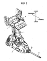
- Fig. 1 shows a motor-driven tool provided with the battery pack according to the invention.
- a drill 1 as the motor-driven tool includes a body part 2 as a body of the apparatus, and a battery pack 10.
- a motor (not shown) and a control part (not shown) for controlling motion of the motor are incorporated in the body part 2, and a tool holding part 2A to which a drill bit 4 can be fitted is provided at a distal end portion of the body part 2.
- a handle 3 is extended downward from a backward end area of the body part, 2, and a trigger 3A is provided at a base end of the extended area.
- the control part will control power supply from the battery pack 10 to the body part 2 through the trigger 3A.
- a plurality of terminals 4 in a plate-like shape are provided at an end of the handle 3 in the extended direction thereof so as to protrude toward the front.
- Two of the plurality of the terminals 4 are power terminals through which electric current for driving the motor flows, and the other terminals are signal transmitting terminals which transmit signals indicating temperature of the battery pack 10 to the control part. Also, the other terminals may serve as terminals for transmitting toward the control part a signal of stopping discharge,that interrupts a power supply from the motor-driven tool 1 to the battery pack 10.
- the battery pack 10 is mounted to a distal end portion of the handle 3 in the extended direction so as to be attached or detached along the longitudinal direction of the body part 2.
- Fig. 1 by inserting the battery pack 10 into the body part 2 in a direction as shown by an arrow mark A along the longitudinal direction of the body part 2, the battery pack 10 will be attached to the body part 2.
- the battery pack 10 will be able to be detached from the body part 2.
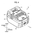
- the battery pack 100 has a group of battery cells 30, a board 40, and a cover 50 in a housing 20 as shown in Fig. 4 so that the battery cells contained therein can be charged and discharged.
- the direction as shown by the arrow mark A is an inserting direction of the housing 20 to be inserted into the body part 2. Therefore, by pushing the housing 20 into the body part 2 along the direction of the arrow mark A, the housing 20 will be able to be attached to the body part 2.
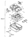
- the housing 20 includes an upper housing 21 and a lower housing 22, as shown in Fig. 5 .
- the upper and lower housings 21, 22 are engaged with each other by means of bosses 22A.
- the housing 20 contains therein the group of battery cells 30, the board 40, and the cover 50 in this order from the lower housing 22 to the upper housing 21.
- the upper housing 21 is formed with a terminal inserting part 21A into which the terminals 4 of the body part 2 are adapted to be inserted.
- a pair of operating pieces 23, 23 for locking the housing 20 to the body part 2 are fitted to both sides of the housing 20 at a front end thereof.
- the terminal inserting part 21A is covered with the cover 50 so that the board 40 may not be exposed to the exterior.
- the group of battery cells 30 includes a plurality of electrically connected battery cells 32 which are contained in a cell frame 31 as a battery cell containing part, and has two electrodes (not shown) which are electrically connected to the battery cells 32.
- Each of the battery cells 32 is a nickel metal hydride battery or a lithium-ion battery which can be charged and discharged at a plurality of times.
- the board 40 is provided above the group of battery cells 30 so as to be positioned inside the upper housing 21.
- a terminal arranging part 41 is provided on an upper face of the board 40 along a length L which extends in a direction perpendicular to the inserting direction A.
- a plurality of terminals 42 to 48 which are adapted to be engaged with the terminals 4 of the body part 2 are arranged on the terminal arranging part 41.
- seven terminals 42 to 48 are arranged on the terminal arranging part 41 at appropriate intervals, as shown in Figs. 5 and 6 , and according to necessity, will be engaged with the terminals 4 of the body part 2 which have been inserted through the terminal inserting part 21A.
- the seven terminals 42 to 48 includes a charging terminal with positive polarity 42, a discharging terminal with positive polarity 43, signal transmitting terminals 44, 45, 46, a charging and discharging terminal with negative polarity 47, and a signal transmitting terminal 48, in this order from one end of the terminal arranging part 41.
- the terminals with positive polarity 42, 43 are connected to one of the electrodes of the group of battery cells 30, while the terminal with negative polarity 47 is connected to the other electrode of the group of battery cells 30.
- the terminals with positive polarity 42, 43 and the terminal with negative polarity 47 are used for passing the electric current corresponding to the charge and discharge of the battery cells 32, between the battery pack 10 and the apparatus attached to the battery pack 10.
- the signal transmitting terminals 44, 45, 46 and 48 are respectively used as a terminal for discriminating types and number of the battery cells which are contained, as a terminal for detecting overcharge, as a terminal for transmitting output from a thermistor, and as a terminal for preventing over-discharge or over-current. In other words, control signals for controlling the charge or discharge of the battery pack 10 will be transmitted through the signal transmitting terminals 44, 45, 46, 48.
- the terminals with positive polarity 42, 43 and the terminal with negative polarity 47 correspond to the first terminals described in the claims, and the signal transmitting terminals 44, 45, 46, 48 correspond to the second terminals.
- the terminals with positive polarity 42, 43 are arranged in one of regions 41A of the terminal arranging part 41 which is divided by a phantom centerline K-K passing a middle of the length L of the terminal arranging part 41 and extending in parallel with the inserting direction A.
- the terminal with negative polarity 47 is arranged in the other region 41B of the terminal arranging part 41 which is divided by the centerline K-K.
- the centerline K-K is interposed between the terminal with negative polarity 47 and either one of the terminals with positive polarity 42, 43.
- the signal transmitting terminals 44, 45, 46, 48 are arranged in the terminal arranging part 41 at appropriate distances from the terminals with positive polarity 42, 43 and the terminal with negative polarity 47.
- each of the terminals 42 to 48 has such a shape that a flat plate of electrically conductive metal is bent into U-shape and portions near an open end of the U-shape are so formed as to be pressure contacted with each other. Therefore, the terminal 42 as an example will be described in detail referring to Fig. 7 .
- the terminal 42 includes two open end portions 42a which are pressure contacted with each other, a bottom portion 42b at which the flat plate is bent into the U-shape, and arm portions 42c which connect the open end portions 42a to the bottom portion 42b.
- the terminal 42 is fixed to the board 40 by means of a leg portion 42d (See Fig. 5 ) which extends from the bottom portion 42b toward the board 40, and electrically connected to a corresponding part of the group of battery cells 30.
- leg portion 42d See Fig. 5
- the open end portions, bottom portions, arm portions of the terminals 42 to 48 will be respectively referred to by affixing a, b, c to the reference numerals of the terminals.
- the terminal 4 of the body part 2 will be pressure fitted into between the open end portions 42a of the terminal 42, and thus, the terminal 42 will be electrically connected to the terminal 4 by the pressure contact between them.
- the terminals with positive polarity 42, 43 and the terminal with negative polarity 47 are formed of a flat plate having a thickness of 0.5mm, as shown in Fig. 8(a) .
- the signal transmitting terminals 44, 45, 46, 48 are formed of a flat plate having a thickness of 0.3mm, as shown in Fig. 8(b) .
- the terminals with positive polarity 42, 43 and the terminal with negative polarity 47 through which the current flows are formed thicker than the signal transmitting terminals 44, 45, 46, 48.
- the terminals with positive polarity 42, 43 and the terminal with negative polarity 47 have higher mechanical strength as compared with the signal transmitting terminals 44, 45, 46, 48, and higher fitting pressure, when they are engaged with the terminals 4.
- the battery pack 10 having the above described structure When the battery pack 10 having the above described structure is attached to the drill 1, the battery pack 10 will be inserted into the distal end part of the handle 3 in the extended direction thereof, along the inserting direction A, as shown in Fig. 1 . Simultaneously, the terminals 4 will be respectively engaged with the terminal with positive polarity 43, the terminal with negative polarity 47, and the signal transmitting terminal 48. On this occasion, the terminals 4 will be pressure fitted into the terminals 43, 47, 48 so as to spread the open end portions 43a, 47a, 48a, whereby the terminal 4 will be engaged with the terminals 43, 47, 48.
- the terminals 43, 47 through which the current from the battery pack 10 flows have wider contact area with respect to the terminals 4 due to the high fitting pressure, increase of contact resistance can be restrained, and generation of heat in the terminals due to the increase of the contact pressure can be restrained.
- the generation of heat is restrained, occurrence of arc between the terminal 43 and the terminal 4, or between the terminal 47 and the terminal 4 will be restrained, whereby damage and blowout of the terminals 43, 47 can be prevented.
- almost no current flows between the signal transmitting terminal 48 and the terminal 4 and therefore, generation of heat in the terminal 48 can be restrained, even though the contact area with respect to the terminal 4 is small because of the low fitting pressure and the contact resistance is large.
- the battery pack 10 can be smoothly attached to the drill 1 without requiring any force.
- the terminals 43, 47 which require higher fitting force are separated from each other and arranged relatively close to both sides of the terminal arranging part 41, the force required for attaching the battery pack 10 to the drill 1 can be dispersed and substantially uniformly exerted over the length L of the terminal arranging part 41. Consequently, the battery pack 10 can be smoothly attached to the drill 1.
- the terminal with positive polarity 42 and the terminal with negativepolarity 47 will be respectively fitted to the power terminals of the charger 100, and the signal transmitting terminals 44, 45, 46 will be respectively fitted to the signal transmitting terminals of the charger 100.
- the fitting pressure of the terminals 42, 47 through which the current flows becomes higher than the fitting pressure of the signal transmitting terminals 44, 45, 46.
- defective contact of the terminals 42, 47 through which the current flows can be restrained, and generation of heat in the terminals 42; 47 can be restrained.
- the battery pack 10 can be smoothly attached to the charger 100 with a reduced force.
- Fig. 9 shows another structure of the terminals 42 to 48.
- the terminals 42 to 48 are formed of flat plates having the same thickness.
- the arm portions 42c, 43c, 47c of the terminals with positive polarity 42, 43 and the terminal with negative polarity 47 as shown in Fig. 9(a) are formed shorter than the arm portions 44c, 45c, 46c, 48c of the signal transmitting terminals 44, 45, 46, 48 as shown in Fig. 9(b) .
- the terminals 42, 43, 47 through which the current flows are so formed that they have higher mechanical strength than the signal transmitting terminals 44, 45, 46, 48, and higher fitting pressure when they are engaged with the terminals 4.
- substantially the same effect as the terminals 42 to 48 which have the structure as shown in Fig. 8 will be obtained.
- Fig. 10 shows still another structure of the terminals 42 to 48.
- the terminals 42 to 48 are formed of flat plates of electrically conductive metal.
- the terminals 42 to 48 are fixed to the board 40 by means of leg portions (not shown) extending from one end portions 42e, 43e, 44e, 45e, 46e, 47e, 48e in the longitudinal direction toward the board 40, and electrically connected to corresponding parts of the group of battery cells 30 or the like.
- the terminals with positive polarity 42, 43 and the terminal with negative polarity 47 are formed of flat plates having a thickness of 0.5mm, as shown in Fig. 10(a) .
- the signal transmitting terminals 44, 45, 46, 48 are formed of flat plates having a thickness of 0.
- the terminals with positive polarity 42, 43 and the terminal with negative polarity 47 through which the current flows are formed thicker than the signal transmitting terminals 44, 45, 46, 48.
- the terminals 42 to 48 of the battery pack 10 are formed in a plate-like shape
- the corresponding terminals 4 of the drill 1 or the charger 100 to which the battery pack 10 is attached are formed in a U-shape having an open end into which the terminals 42 to 48 are adapted to be inserted.
- the fitting pressure of the terminals through which the current flows becomes higher than the fitting pressure of the signal transmitting terminals, when the terminals 42 to 48 are pressure fitted to the corresponding terminals 4 of the drill 1 or the charger 100, whereby substantially the same effect as the terminals as shown in Fig. 8 will be obtained.
- the battery pack 10 in which the number of the terminals is seven has been described, the number of the terminals is not limited to seven.
- the battery pack according to the invention can be attached to a potable motor-driven tool such as a drill, an impact driver, and so on.
Applications Claiming Priority (1)
| Application Number | Priority Date | Filing Date | Title |
|---|---|---|---|
| JP2006243386A JP4333715B2 (ja) | 2006-09-07 | 2006-09-07 | 電池パック、充電器、及び電動工具 |
Publications (2)
| Publication Number | Publication Date |
|---|---|
| EP1909344A1 EP1909344A1 (en) | 2008-04-09 |
| EP1909344B1 true EP1909344B1 (en) | 2014-11-05 |
Family
ID=39030824
Family Applications (1)
| Application Number | Title | Priority Date | Filing Date |
|---|---|---|---|
| EP07017596.3A Revoked EP1909344B1 (en) | 2006-09-07 | 2007-09-07 | Battery pack, and assembly of battery pack and motor-driven tool or charger |
Country Status (4)
| Country | Link |
|---|---|
| US (1) | US7759899B2 (zh) |
| EP (1) | EP1909344B1 (zh) |
| JP (1) | JP4333715B2 (zh) |
| CN (1) | CN101140984B (zh) |
Families Citing this family (18)
| Publication number | Priority date | Publication date | Assignee | Title |
|---|---|---|---|---|
| JP4993176B2 (ja) * | 2006-09-07 | 2012-08-08 | 日立工機株式会社 | 電池パック及び電池パックを用いた電動工具 |
| JP5523905B2 (ja) * | 2010-04-13 | 2014-06-18 | 株式会社マキタ | 端子接続構造 |
| US20120189892A1 (en) * | 2011-01-26 | 2012-07-26 | Alma Gilgen | Removable Battery Pack and Replaceable Cartridges |
| JP5553053B2 (ja) * | 2011-04-11 | 2014-07-16 | マックス株式会社 | 電池パック、電動工具及び充電器 |
| TWI371883B (en) * | 2011-07-08 | 2012-09-01 | Simplo Technology Company Ltd | Battery module and related forming method,battery cell assembly,bus layout structure of a battery module and related layout method,cpnnection structure and connection method between battery cells and conductiog buses of a battery module, and connection s |
| CN103390812A (zh) * | 2012-05-10 | 2013-11-13 | 凡甲电子(苏州)有限公司 | 电连接器 |
| JP6091968B2 (ja) * | 2013-04-04 | 2017-03-08 | 株式会社マキタ | 電動工具用電池パック |
| JP6577229B2 (ja) * | 2015-02-13 | 2019-09-18 | 株式会社マキタ | バッテリパック、及びバッテリシステム |
| US10348110B2 (en) | 2015-02-13 | 2019-07-09 | Makita Corporation | Battery pack |
| JP6581824B2 (ja) * | 2015-07-06 | 2019-09-25 | 株式会社マキタ | 電池パック |
| CN109075299B (zh) | 2016-02-26 | 2021-08-31 | 创科(澳门离岸商业服务)有限公司 | 电池组和组装电池组的方法 |
| DE102016120329A1 (de) * | 2016-10-25 | 2018-04-26 | Festool Gmbh | Anschlussvorrichtung eines Elektrogeräts oder eines Energiespeichers |
| WO2018226945A1 (en) * | 2017-06-09 | 2018-12-13 | Stryker Corporation | Surgical systems with twist-lock battery connection |
| EP3444905A1 (de) * | 2017-08-18 | 2019-02-20 | HILTI Aktiengesellschaft | Steckkupplung für eine akkueinheit |
| CN112771730B (zh) | 2018-09-27 | 2024-04-26 | 本田技研工业株式会社 | 公连接器和具有该公连接器的收容装置 |
| JP7022953B2 (ja) * | 2019-01-30 | 2022-02-21 | パナソニックIpマネジメント株式会社 | ケア機器用の充電台 |
| KR20210025294A (ko) * | 2019-08-27 | 2021-03-09 | 주식회사 엘지화학 | 커넥터 |
| US20210098757A1 (en) | 2019-09-30 | 2021-04-01 | Makita Corporation | Battery pack |
Family Cites Families (8)
| Publication number | Priority date | Publication date | Assignee | Title |
|---|---|---|---|---|
| JP3003243B2 (ja) * | 1991-03-18 | 2000-01-24 | ソニー株式会社 | バッテリー |
| US5470255A (en) | 1993-03-23 | 1995-11-28 | The Whitaker Corporation | Extended height connector for a battery |
| JP2711223B2 (ja) | 1994-07-29 | 1998-02-10 | インターナショナル・ビジネス・マシーンズ・コーポレイション | バッテリパック及びその接続構造 |
| JP3698296B2 (ja) | 1999-08-19 | 2005-09-21 | 株式会社マキタ | 端子構造 |
| DE20023631U1 (de) | 1999-08-19 | 2005-05-19 | Makita Corp., Anjo | Struktur von elektrischen Anschlüssen zum Herstellen eines elektrischen Kontakts zwischen einem Batterieteil und einer elektrischen Vorrichtung |
| EP1128517A3 (en) * | 2000-02-24 | 2003-12-10 | Makita Corporation | Adapters for rechargeable battery packs |
| CA2347604A1 (en) | 2000-05-25 | 2001-11-25 | Berg Technology, Inc. | Electrical connector capable of exerting a selectively variable contact force |
| WO2003010840A1 (en) | 2001-07-25 | 2003-02-06 | Sony Corporation | Terminal structure and mounting part |
-
2006
- 2006-09-07 JP JP2006243386A patent/JP4333715B2/ja not_active Expired - Fee Related
-
2007
- 2007-09-06 US US11/850,906 patent/US7759899B2/en not_active Expired - Fee Related
- 2007-09-07 CN CN2007101476956A patent/CN101140984B/zh not_active Expired - Fee Related
- 2007-09-07 EP EP07017596.3A patent/EP1909344B1/en not_active Revoked
Also Published As
| Publication number | Publication date |
|---|---|
| CN101140984A (zh) | 2008-03-12 |
| US20080061738A1 (en) | 2008-03-13 |
| JP2008066148A (ja) | 2008-03-21 |
| EP1909344A1 (en) | 2008-04-09 |
| JP4333715B2 (ja) | 2009-09-16 |
| CN101140984B (zh) | 2010-09-15 |
| US7759899B2 (en) | 2010-07-20 |
Similar Documents
| Publication | Publication Date | Title |
|---|---|---|
| EP1909344B1 (en) | Battery pack, and assembly of battery pack and motor-driven tool or charger | |
| JP5198274B2 (ja) | 電気的な接続のための新規なバスバーおよびそれを備えた電池モジュール | |
| US9385401B2 (en) | Rechargeable battery pack and electrical hand tool device | |
| US8684106B2 (en) | Battery pack and motor-driven tool using the same | |
| EP2107624B1 (en) | Battery pack | |
| EP1878071B1 (en) | Improved middle or large-sized battery pack of increased safety | |
| EP2207222B1 (en) | Battery pack | |
| US8252455B2 (en) | Battery pack, vehicle equipped with the battery pack, and device equipped with the battery pack | |
| JP5450634B2 (ja) | 新規な構造を有する二次電池パック | |
| CN111279522B (zh) | 电池模块、电池组和包括该电池组的装置 | |
| JP5083630B2 (ja) | 電池パック、電動工具、充電器 | |
| CN107710456B (zh) | 汇流条结构 | |
| JP2012014963A (ja) | 車両用の電源装置 | |
| JP7276491B2 (ja) | 電池パック及び電気機器 | |
| EP1826841B1 (en) | Charging apparatus | |
| KR101669116B1 (ko) | 센싱부재가 마련된 배터리 모듈 | |
| KR20160139807A (ko) | 배터리 팩 | |
| KR20170040636A (ko) | 배터리 모듈 및 이를 포함하는 배터리 팩 | |
| KR20170043928A (ko) | 배터리 모듈 및 그 제조방법 | |
| KR101783333B1 (ko) | 모듈용 단자 | |
| JP5476603B2 (ja) | 車両用電池パック | |
| JP5605133B2 (ja) | 電池パック | |
| CN217768682U (zh) | 采样组件、电池及用电装置 | |
| CN115117515A (zh) | 电池组 | |
| KR20240022975A (ko) | 배터리 팩 및 이를 포함하는 전자 디바이스 |
Legal Events
| Date | Code | Title | Description |
|---|---|---|---|
| PUAI | Public reference made under article 153(3) epc to a published international application that has entered the european phase |
Free format text: ORIGINAL CODE: 0009012 |
|
| AK | Designated contracting states |
Kind code of ref document: A1 Designated state(s): AT BE BG CH CY CZ DE DK EE ES FI FR GB GR HU IE IS IT LI LT LU LV MC MT NL PL PT RO SE SI SK TR |
|
| AX | Request for extension of the european patent |
Extension state: AL BA HR MK RS |
|
| 17P | Request for examination filed |
Effective date: 20081009 |
|
| AKX | Designation fees paid |
Designated state(s): DE FR GB |
|
| 17Q | First examination report despatched |
Effective date: 20100316 |
|
| GRAP | Despatch of communication of intention to grant a patent |
Free format text: ORIGINAL CODE: EPIDOSNIGR1 |
|
| RIC1 | Information provided on ipc code assigned before grant |
Ipc: B25F 5/00 20060101ALI20140313BHEP Ipc: H01M 2/30 20060101AFI20140313BHEP Ipc: H01M 10/48 20060101ALI20140313BHEP Ipc: H01M 2/10 20060101ALI20140313BHEP Ipc: H01M 2/20 20060101ALI20140313BHEP Ipc: H01R 13/11 20060101ALI20140313BHEP |
|
| INTG | Intention to grant announced |
Effective date: 20140415 |
|
| GRAS | Grant fee paid |
Free format text: ORIGINAL CODE: EPIDOSNIGR3 |
|
| RIN1 | Information on inventor provided before grant (corrected) |
Inventor name: SAITO, KEITA Inventor name: NAKAGAWA, ATSUSHI Inventor name: HANAWA, HIROYUKI |
|
| GRAA | (expected) grant |
Free format text: ORIGINAL CODE: 0009210 |
|
| AK | Designated contracting states |
Kind code of ref document: B1 Designated state(s): DE FR GB |
|
| REG | Reference to a national code |
Ref country code: GB Ref legal event code: FG4D |
|
| REG | Reference to a national code |
Ref country code: DE Ref legal event code: R096 Ref document number: 602007039101 Country of ref document: DE Effective date: 20141218 |
|
| REG | Reference to a national code |
Ref country code: DE Ref legal event code: R026 Ref document number: 602007039101 Country of ref document: DE |
|
| PLBI | Opposition filed |
Free format text: ORIGINAL CODE: 0009260 |
|
| PLAX | Notice of opposition and request to file observation + time limit sent |
Free format text: ORIGINAL CODE: EPIDOSNOBS2 |
|
| 26 | Opposition filed |
Opponent name: ANDREAS STIHL AG & CO. KG Effective date: 20150805 |
|
| PLBB | Reply of patent proprietor to notice(s) of opposition received |
Free format text: ORIGINAL CODE: EPIDOSNOBS3 |
|
| REG | Reference to a national code |
Ref country code: FR Ref legal event code: PLFP Year of fee payment: 10 |
|
| REG | Reference to a national code |
Ref country code: FR Ref legal event code: PLFP Year of fee payment: 11 |
|
| PGFP | Annual fee paid to national office [announced via postgrant information from national office to epo] |
Ref country code: GB Payment date: 20170906 Year of fee payment: 11 Ref country code: FR Payment date: 20170810 Year of fee payment: 11 Ref country code: DE Payment date: 20170830 Year of fee payment: 11 |
|
| REG | Reference to a national code |
Ref country code: DE Ref legal event code: R064 Ref document number: 602007039101 Country of ref document: DE Ref country code: DE Ref legal event code: R103 Ref document number: 602007039101 Country of ref document: DE |
|
| RDAF | Communication despatched that patent is revoked |
Free format text: ORIGINAL CODE: EPIDOSNREV1 |
|
| REG | Reference to a national code |
Ref country code: DE Ref legal event code: R082 Ref document number: 602007039101 Country of ref document: DE Representative=s name: STREHL SCHUEBEL-HOPF & PARTNER MBB PATENTANWAE, DE Ref country code: DE Ref legal event code: R081 Ref document number: 602007039101 Country of ref document: DE Owner name: KOKI HOLDINGS CO., LTD., JP Free format text: FORMER OWNER: HITACHI KOKI CO., LTD., TOKYO, JP |
|
| RAP2 | Party data changed (patent owner data changed or rights of a patent transferred) |
Owner name: KOKI HOLDINGS KABUSHIKI KAISHA |
|
| RDAG | Patent revoked |
Free format text: ORIGINAL CODE: 0009271 |
|
| STAA | Information on the status of an ep patent application or granted ep patent |
Free format text: STATUS: PATENT REVOKED |
|
| 27W | Patent revoked |
Effective date: 20171122 |
|
| GBPR | Gb: patent revoked under art. 102 of the ep convention designating the uk as contracting state |
Effective date: 20171122 |