EP1908970A1 - Nadellager und lagerstruktur - Google Patents
Nadellager und lagerstruktur Download PDFInfo
- Publication number
- EP1908970A1 EP1908970A1 EP06768243A EP06768243A EP1908970A1 EP 1908970 A1 EP1908970 A1 EP 1908970A1 EP 06768243 A EP06768243 A EP 06768243A EP 06768243 A EP06768243 A EP 06768243A EP 1908970 A1 EP1908970 A1 EP 1908970A1
- Authority
- EP
- European Patent Office
- Prior art keywords
- outer ring
- needle roller
- roller bearing
- retainer
- ring member
- Prior art date
- Legal status (The legal status is an assumption and is not a legal conclusion. Google has not performed a legal analysis and makes no representation as to the accuracy of the status listed.)
- Granted
Links
Images


Classifications
-
- F—MECHANICAL ENGINEERING; LIGHTING; HEATING; WEAPONS; BLASTING
- F16—ENGINEERING ELEMENTS AND UNITS; GENERAL MEASURES FOR PRODUCING AND MAINTAINING EFFECTIVE FUNCTIONING OF MACHINES OR INSTALLATIONS; THERMAL INSULATION IN GENERAL
- F16C—SHAFTS; FLEXIBLE SHAFTS; ELEMENTS OR CRANKSHAFT MECHANISMS; ROTARY BODIES OTHER THAN GEARING ELEMENTS; BEARINGS
- F16C33/00—Parts of bearings; Special methods for making bearings or parts thereof
- F16C33/30—Parts of ball or roller bearings
- F16C33/46—Cages for rollers or needles
- F16C33/4694—Single-split roller or needle cages
-
- F—MECHANICAL ENGINEERING; LIGHTING; HEATING; WEAPONS; BLASTING
- F16—ENGINEERING ELEMENTS AND UNITS; GENERAL MEASURES FOR PRODUCING AND MAINTAINING EFFECTIVE FUNCTIONING OF MACHINES OR INSTALLATIONS; THERMAL INSULATION IN GENERAL
- F16C—SHAFTS; FLEXIBLE SHAFTS; ELEMENTS OR CRANKSHAFT MECHANISMS; ROTARY BODIES OTHER THAN GEARING ELEMENTS; BEARINGS
- F16C19/00—Bearings with rolling contact, for exclusively rotary movement
- F16C19/22—Bearings with rolling contact, for exclusively rotary movement with bearing rollers essentially of the same size in one or more circular rows, e.g. needle bearings
- F16C19/44—Needle bearings
- F16C19/46—Needle bearings with one row or needles
- F16C19/466—Needle bearings with one row or needles comprising needle rollers and an outer ring, i.e. subunit without inner ring
-
- F—MECHANICAL ENGINEERING; LIGHTING; HEATING; WEAPONS; BLASTING
- F16—ENGINEERING ELEMENTS AND UNITS; GENERAL MEASURES FOR PRODUCING AND MAINTAINING EFFECTIVE FUNCTIONING OF MACHINES OR INSTALLATIONS; THERMAL INSULATION IN GENERAL
- F16C—SHAFTS; FLEXIBLE SHAFTS; ELEMENTS OR CRANKSHAFT MECHANISMS; ROTARY BODIES OTHER THAN GEARING ELEMENTS; BEARINGS
- F16C33/00—Parts of bearings; Special methods for making bearings or parts thereof
- F16C33/30—Parts of ball or roller bearings
- F16C33/46—Cages for rollers or needles
- F16C33/4617—Massive or moulded cages having cage pockets surrounding the rollers, e.g. machined window cages
- F16C33/4623—Massive or moulded cages having cage pockets surrounding the rollers, e.g. machined window cages formed as one-piece cages, i.e. monoblock cages
- F16C33/4635—Massive or moulded cages having cage pockets surrounding the rollers, e.g. machined window cages formed as one-piece cages, i.e. monoblock cages made from plastic, e.g. injection moulded window cages
-
- F—MECHANICAL ENGINEERING; LIGHTING; HEATING; WEAPONS; BLASTING
- F16—ENGINEERING ELEMENTS AND UNITS; GENERAL MEASURES FOR PRODUCING AND MAINTAINING EFFECTIVE FUNCTIONING OF MACHINES OR INSTALLATIONS; THERMAL INSULATION IN GENERAL
- F16C—SHAFTS; FLEXIBLE SHAFTS; ELEMENTS OR CRANKSHAFT MECHANISMS; ROTARY BODIES OTHER THAN GEARING ELEMENTS; BEARINGS
- F16C33/00—Parts of bearings; Special methods for making bearings or parts thereof
- F16C33/30—Parts of ball or roller bearings
- F16C33/58—Raceways; Race rings
- F16C33/60—Raceways; Race rings divided or split, e.g. comprising two juxtaposed rings
-
- F—MECHANICAL ENGINEERING; LIGHTING; HEATING; WEAPONS; BLASTING
- F16—ENGINEERING ELEMENTS AND UNITS; GENERAL MEASURES FOR PRODUCING AND MAINTAINING EFFECTIVE FUNCTIONING OF MACHINES OR INSTALLATIONS; THERMAL INSULATION IN GENERAL
- F16C—SHAFTS; FLEXIBLE SHAFTS; ELEMENTS OR CRANKSHAFT MECHANISMS; ROTARY BODIES OTHER THAN GEARING ELEMENTS; BEARINGS
- F16C35/00—Rigid support of bearing units; Housings, e.g. caps, covers
- F16C35/04—Rigid support of bearing units; Housings, e.g. caps, covers in the case of ball or roller bearings
- F16C35/06—Mounting or dismounting of ball or roller bearings; Fixing them onto shaft or in housing
- F16C35/067—Fixing them in a housing
-
- F—MECHANICAL ENGINEERING; LIGHTING; HEATING; WEAPONS; BLASTING
- F16—ENGINEERING ELEMENTS AND UNITS; GENERAL MEASURES FOR PRODUCING AND MAINTAINING EFFECTIVE FUNCTIONING OF MACHINES OR INSTALLATIONS; THERMAL INSULATION IN GENERAL
- F16C—SHAFTS; FLEXIBLE SHAFTS; ELEMENTS OR CRANKSHAFT MECHANISMS; ROTARY BODIES OTHER THAN GEARING ELEMENTS; BEARINGS
- F16C9/00—Bearings for crankshafts or connecting-rods; Attachment of connecting-rods
- F16C9/02—Crankshaft bearings
-
- F—MECHANICAL ENGINEERING; LIGHTING; HEATING; WEAPONS; BLASTING
- F16—ENGINEERING ELEMENTS AND UNITS; GENERAL MEASURES FOR PRODUCING AND MAINTAINING EFFECTIVE FUNCTIONING OF MACHINES OR INSTALLATIONS; THERMAL INSULATION IN GENERAL
- F16C—SHAFTS; FLEXIBLE SHAFTS; ELEMENTS OR CRANKSHAFT MECHANISMS; ROTARY BODIES OTHER THAN GEARING ELEMENTS; BEARINGS
- F16C2226/00—Joining parts; Fastening; Assembling or mounting parts
- F16C2226/50—Positive connections
Definitions
- the present invention relates to a needle roller bearing and a bearing structure that support a crankshaft, a camshaft, a balance shaft, and a rocker shaft of a car and the like.
- a needle roller bearing is used instead of the sliding bearing in some cases.
- the needle roller bearing has low load capacity as compared with the sliding bearing, since its friction resistance during rotation is small, an oil amount at a supporting part can be reduced.
- the needle roller bearing comprises an outer ring, a plurality of needle rollers rotatably arranged on the raceway surface of the outer ring, and a retainer retaining the needle rollers.
- the outer ring comprises outer ring members 4a and 4b split by a parting line extending in the axial direction of the bearing as shown in Fig. 7 , so that it can be incorporated in the crank pin 2. The same is true of the retainer.
- the above needle roller bearing and a housing holding the outer ring of the needle roller bearing are separately manufactured in general. As a result, an error between a curvature radius of the outer ring and a curvature radius of the inner diameter of the housing could be generated.
- a needle roller bearing according to the present invention comprises an outer ring having a plurality of outer ring members split by a parting line extending in the axial direction of the bearing, a plurality of needle rollers rotatably arranged on the raceway surface of the outer ring, and a retainer retaining the plurality of needle rollers.
- a curvature radius r 1 of the outer ring member and a curvature radius r 2 of the outer diameter of the retainer has a relation such that 1 ⁇ r 1 / r 2 ⁇ 1.30.
- the outer ring member is elastically deformed and has an appropriate configuration along the inner diameter surface of the housing.
- the needle roller bearing can maintain the smooth rotation of the needle roller.
- the outer ring member has an engagement part engaging with the housing to be positioned, at a position shifted from the center in its circumferential direction.
- the positioning engagement part is provided in the outer ring member to prevent the rotation of the outer ring in the circumferential direction.
- the needle roller bearing comprises a retainer retaining intervals between the plurality of needle rollers and the outer ring member has an engagement click provided at an end in its width direction and protruding toward the inner side in its diameter direction to prevent the retainer from moving in the axial direction.
- the engagement click is provided at the end of the outer ring member in the width direction, the retainer is prevented from moving in the axial direction without processing a peripheral structure such as a shaft.
- a bearing structure comprises a needle roller bearing comprising an outer ring having a plurality of outer ring members split by a parting line extending in the axial direction of the bearing, a plurality of needle rollers rotatably arranged on the raceway surface of the outer ring, and a retainer retaining the plurality of needle rollers, and a housing holding the outer ring of the needle roller bearing.
- a curvature radius r 1 of the outer ring member and a curvature radius r 3 of the inner diameter of the housing has a relation such that 1 ⁇ r 1 / r 3 ⁇ 1.30.
- the outer ring member is elastically deformed and has an appropriate configuration along the inner diameter surface of the housing.
- the needle roller bearing can maintain the smooth rotation of the needle roller bearing.
- the needle roller bearing and the bearing structure can maintain the smooth rotation of the needle rollers.
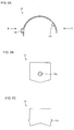
- a needle roller bearing 11 according to one embodiment of the present invention will be described with reference to Figs. 1A to 3B hereinafter.
- the needle roller bearing 11 comprises an outer ring 13 having two outer ring members 12 split by a parting line extending in the axial direction of the bearing, a plurality of needle rollers 14 rotatably arranged on the raceway surface of the outer ring 13, and a retainer 15 retaining the needle rollers 14.
- the parting line of the outer ring 13 may only have to split the outer ring 13 in the diameter direction and it does not always coincide with the axial direction strictly.
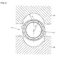
- a curvature radius r 1 of the outer ring member 12 and a curvature radius r 2 of an outer diameter of the retainer 15 satisfy a relation such that 1 ⁇ r 1 / r 2 ⁇ ⁇ .
- a value ⁇ varies depending on a thickness "t" of the outer ring member 12 as shown in Table 1.
- Table 1 Relation of curvature radiuses between outer ring and retainer outer diameter Thickness "t" 0 ⁇ t ⁇ 0.8 0.8 ⁇ t ⁇ 1.2 1.2 ⁇ t ⁇ 2.0 2.0 ⁇ t ⁇ 1.30 1.25 1.20 1.15
- the value ⁇ varies depending on the thickness "t" of the outer ring member 12 as shown in Table 1.
- the reason why the value of the ⁇ is increased as the thickness "t" is reduced is that as the thickness becomes small, elastic deformability becomes high.
- the needle roller bearing 11 when the needle roller bearing 11 is incorporated in the housing, since the outer ring member 12 is elastically deformed and has a configuration along the housing, the needle roller bearing 11 can maintain the smooth rotation of the needle rollers 14.
- the outer ring member 12 comprises a projection 12a at a position shifted from the center in the circumferential direction thereof as an engagement part with the housing to be positioned, and an engagement click 12b projecting from an end of the outer ring member 12 in the width direction toward inner side in the diameter direction, to prevent the retainer 15 from moving in the axial direction.
- one end of the outer ring member 12 in the circumferential direction is projected and the other end thereof is recessed, and the cylindrical outer ring 13 is formed by coupling the projected and the recessed parts.
- the needle roller bearing 11 since a part of the outer ring 13 and a part of the retainer 15 are cut, it can be used as a bearing that supports a component such as a crankshaft, a camshaft, a balance shaft, a rocker shaft of a car and that like in which a bearing cannot be press fitted in the axial direction.
- the projection 12a is provided in the outer ring member 12 to prevent the outer ring 13 from rotating in the circumferential direction, and the engagement click 12b is provided to prevent the retainer 15 from moving in the axial direction.
- the retainer 15 is formed of a resin material and has pockets to hold the needle rollers 14 in the circumferential direction as shown in Fig. 3A .
- it has a joint comprising a projected part 15a and a recessed part 15b at an abutment end provided on a circumference and cut in the axial direction in which cut surfaces abut on each other.
- the retainer 15 is elastically deformed to be incorporated in a shaft and then the projected part 15a and the recessed part 15b of the cut surfaces are joined to prevent the abutment end from being shifted in the axial direction.
- the joint comprising the projected part 15a and the recessed part 15b prevents one of the cut surface from shifting in the axial direction.
- a joint comprises one projected part 15a and one recessed part 15b in the above embodiment, the present invention is not limited to this.
- a joint may comprise a plurality of combined projected parts and recessed parts.
- outer ring 13 comprises the two outer ring members 12 split in the diameter direction in the above embodiment, the present invention is not limited to this.
- an outer ring may be split into any number.
- each outer ring member 2 may be provided in each outer ring member 2 in the above embodiment, the present invention is not limited to this. They may be provided over the entire circumference of the outer ring 13 or a plurality of them may be provided in each outer ring member 12.
- an engagement click 12b may be provided over an entire end of the outer ring member in the axial direction.
- the retainer 15 may be formed of a metal material using a pressing process instead of a resin, or the present invention may be applied to a full-type roller bearing without comprising the retainer 15.
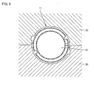
- the curvature radius r 1 of the outer ring member 12 and a curvature radius r 3 of the inner diameter of the housing 20 satisfy a relation such that 1 ⁇ r 1 / r 3 ⁇ ⁇ .
- a value ⁇ varies depending on the thickness "t" of the outer ring member 12 as shown in Table 2.
- Table 2 Relation of curvature radiuses between outer ring and housing inner diameter Thickness "t" 0 ⁇ t ⁇ 0.8 0.8 ⁇ t ⁇ 1.2 1.2 ⁇ t ⁇ 2.0 2.0 ⁇ t ⁇ 1.30 1.25 1.20 1.15
- the value ⁇ that satisfies r 1 / r 3 ⁇ ⁇ varies depending on the thickness "t" of the outer ring member 12 as shown in Table 2.
- the reason why the value of the ⁇ is increased as the thickness "t" is reduced is that as the thickness becomes small, the elastic deformability becomes high.
- the needle roller bearing 11 that supports a rotation shaft 21 is incorporated in the housing 20, since the outer ring member 12 is elastically deformed and has a configuration along the housing 20 as shown in Fig. 5 , the needle roller bearing 11 can maintain the smooth rotation of the needle rollers 14.
- the present invention can be advantageously applied to a needle roller bearing that supports a crankshaft, a camshaft, a balance shaft, and a rocker shaft of a car, and the like.
Landscapes
- Engineering & Computer Science (AREA)
- General Engineering & Computer Science (AREA)
- Mechanical Engineering (AREA)
- Rolling Contact Bearings (AREA)
- Mounting Of Bearings Or Others (AREA)
Applications Claiming Priority (2)
| Application Number | Priority Date | Filing Date | Title |
|---|---|---|---|
| JP2005215793A JP4790341B2 (ja) | 2005-07-26 | 2005-07-26 | 針状ころ軸受および軸受構造 |
| PCT/JP2006/314083 WO2007013316A1 (ja) | 2005-07-26 | 2006-07-14 | 針状ころ軸受および軸受構造 |
Publications (3)
| Publication Number | Publication Date |
|---|---|
| EP1908970A1 true EP1908970A1 (de) | 2008-04-09 |
| EP1908970A4 EP1908970A4 (de) | 2010-03-03 |
| EP1908970B1 EP1908970B1 (de) | 2013-04-10 |
Family
ID=37683217
Family Applications (1)
| Application Number | Title | Priority Date | Filing Date |
|---|---|---|---|
| EP06768243.5A Ceased EP1908970B1 (de) | 2005-07-26 | 2006-07-14 | Nadellager und lagerstruktur |
Country Status (5)
| Country | Link |
|---|---|
| US (1) | US8128291B2 (de) |
| EP (1) | EP1908970B1 (de) |
| JP (1) | JP4790341B2 (de) |
| CN (1) | CN101228361B (de) |
| WO (1) | WO2007013316A1 (de) |
Families Citing this family (16)
| Publication number | Priority date | Publication date | Assignee | Title |
|---|---|---|---|---|
| WO2008029715A1 (en) * | 2006-09-04 | 2008-03-13 | Ntn Corporation | Roller bearing, camshaft supporting structure, and internal combustion engine |
| JP5071775B2 (ja) * | 2007-03-14 | 2012-11-14 | 株式会社ジェイテクト | 2分割外輪及びそれを用いたころ軸受 |
| EP2511560B1 (de) | 2007-06-28 | 2016-10-12 | NTN Corporation | Kipplager und Montagestruktur für Aussenring eines Kipplagers |
| JP2009174611A (ja) * | 2008-01-23 | 2009-08-06 | Toyota Motor Corp | 転がり軸受 |
| EP2801728B1 (de) * | 2008-05-19 | 2016-08-24 | JTEKT Corporation | Geteiltes Wälzlager |
| CN102348901B (zh) | 2009-03-11 | 2015-11-25 | Ntn株式会社 | 双切口对开式外圈、滚子轴承及旋转轴支承结构 |
| DE102009031064A1 (de) * | 2009-06-30 | 2011-01-05 | Schaeffler Technologies Gmbh & Co. Kg | Lageranordnung mit einer Welle und einem Nadellager |
| JP5762698B2 (ja) * | 2010-06-24 | 2015-08-12 | Ntn株式会社 | 分割型ニードル軸受及び軸受装置 |
| WO2011142240A1 (ja) * | 2010-05-11 | 2011-11-17 | Ntn株式会社 | 分割型ニードル軸受及び内燃機関の潤滑装置 |
| DE102010036093A1 (de) * | 2010-09-01 | 2012-03-01 | Becker Marine Systems Gmbh & Co. Kg | Lagerelement eines Ruderschaftlagers |
| CN102549284B (zh) * | 2010-09-14 | 2015-04-01 | 日本精工株式会社 | 单剖分式保持架 |
| CN103089797A (zh) * | 2011-11-01 | 2013-05-08 | 杨嘉明 | 梳齿瓦楔合滚动轴承 |
| EP2791520B1 (de) | 2011-12-13 | 2019-07-31 | Koyo Bearings North America LLC | Lageraussenschale |
| DE102011088868A1 (de) * | 2011-12-16 | 2013-06-20 | Schaeffler Technologies AG & Co. KG | Radial-Rollenwälzlageranordnung, insbesondere für eine Nadelhülse |
| CN103746501A (zh) * | 2014-01-03 | 2014-04-23 | 绍兴摩泰机电科技有限公司 | 电机盖与轴承的连接结构 |
| JP7557340B2 (ja) * | 2020-10-29 | 2024-09-27 | Ntn株式会社 | 軸受装置 |
Family Cites Families (10)
| Publication number | Priority date | Publication date | Assignee | Title |
|---|---|---|---|---|
| US1921488A (en) | 1932-09-03 | 1933-08-08 | Smith Thomas Noah | Bearing |
| FR2193443A5 (de) * | 1972-07-24 | 1974-02-15 | Pitner Alfred | |
| EP0013628A1 (de) * | 1979-01-15 | 1980-07-23 | The Torrington Company | Rollenlager |
| JP3046645B2 (ja) * | 1991-05-30 | 2000-05-29 | エヌティエヌ株式会社 | 分割軸受の軌道輪製造方法 |
| US5419641A (en) * | 1993-02-10 | 1995-05-30 | Nsk Ltd. | Radial needle bearing |
| CN2237144Y (zh) * | 1995-11-25 | 1996-10-09 | 郑贵滨 | 分体式滚动轴承 |
| CN2338536Y (zh) * | 1998-08-16 | 1999-09-15 | 李建设 | 卡套式滚针轴承 |
| JP2003254327A (ja) * | 2002-03-04 | 2003-09-10 | Ntn Corp | スラスト軸受 |
| US7311447B2 (en) | 2003-09-19 | 2007-12-25 | Nsk Ltd. | Roller bearing |
| JP2005180459A (ja) * | 2003-11-27 | 2005-07-07 | Nsk Ltd | ころ軸受、レース板の製造方法及び保持体の製造方法 |
-
2005
- 2005-07-26 JP JP2005215793A patent/JP4790341B2/ja not_active Expired - Fee Related
-
2006
- 2006-07-14 WO PCT/JP2006/314083 patent/WO2007013316A1/ja not_active Ceased
- 2006-07-14 EP EP06768243.5A patent/EP1908970B1/de not_active Ceased
- 2006-07-14 CN CN2006800271064A patent/CN101228361B/zh not_active Expired - Fee Related
- 2006-07-14 US US11/989,421 patent/US8128291B2/en not_active Expired - Fee Related
Also Published As
| Publication number | Publication date |
|---|---|
| JP2007032671A (ja) | 2007-02-08 |
| CN101228361A (zh) | 2008-07-23 |
| US20090136169A1 (en) | 2009-05-28 |
| JP4790341B2 (ja) | 2011-10-12 |
| WO2007013316A1 (ja) | 2007-02-01 |
| US8128291B2 (en) | 2012-03-06 |
| EP1908970B1 (de) | 2013-04-10 |
| EP1908970A4 (de) | 2010-03-03 |
| CN101228361B (zh) | 2010-06-16 |
Similar Documents
| Publication | Publication Date | Title |
|---|---|---|
| EP1908970A1 (de) | Nadellager und lagerstruktur | |
| US7896557B2 (en) | Needle roller bearing | |
| JP2007255711A (ja) | 球面滑り軸受け及び球面滑り軸受けと結合するハウジング | |
| US7101285B2 (en) | Cross-shaped joint | |
| EP1377754B1 (de) | Herstellungsverfahren einer kegellageranordnung | |
| US20070116393A1 (en) | Needle roller bearing, crank shaft supporting structure, and split method of outer ring of needle roller bearing | |
| EP1947354A1 (de) | Nadellager | |
| EP1860337B1 (de) | Nadellager | |
| JP5982753B2 (ja) | 円すいころ軸受の組立方法 | |
| GB2378988A (en) | Radial-axial rolling bearing | |
| JPS639720A (ja) | 転がり軸受のすきま補正装置 | |
| JP6037063B2 (ja) | 円すいころ軸受の組立方法 | |
| US12504044B2 (en) | Double-row tapered roller bearing assembling jig, and assembling method for double-row tapered roller bearing | |
| JP4480636B2 (ja) | 針状ころ軸受 | |
| JPH08159150A (ja) | スラストころ軸受 | |
| US8267590B2 (en) | Plunger driving structure | |
| JP2004084707A (ja) | ころ軸受 | |
| JP2024176724A (ja) | ころ軸受 | |
| GB2278650A (en) | Rolling bearing for high temperature applications | |
| JPH0814251A (ja) | スラストころ軸受用保持器 | |
| JP2006349031A (ja) | 円錐ころ軸受 | |
| JP2004108513A (ja) | ころ軸受 | |
| JP4563884B2 (ja) | 針状ころ軸受 | |
| JP2016053423A (ja) | 円すいころ軸受 | |
| JP2013076429A (ja) | 円すいころ軸受 |
Legal Events
| Date | Code | Title | Description |
|---|---|---|---|
| PUAI | Public reference made under article 153(3) epc to a published international application that has entered the european phase |
Free format text: ORIGINAL CODE: 0009012 |
|
| 17P | Request for examination filed |
Effective date: 20080125 |
|
| AK | Designated contracting states |
Kind code of ref document: A1 Designated state(s): DE FR |
|
| DAX | Request for extension of the european patent (deleted) | ||
| RBV | Designated contracting states (corrected) |
Designated state(s): DE FR |
|
| A4 | Supplementary search report drawn up and despatched |
Effective date: 20100128 |
|
| RIC1 | Information provided on ipc code assigned before grant |
Ipc: F16C 33/46 20060101ALI20100122BHEP Ipc: F16C 35/067 20060101ALI20100122BHEP Ipc: F16C 33/60 20060101ALI20100122BHEP Ipc: F16C 9/02 20060101ALI20100122BHEP Ipc: F16C 19/46 20060101AFI20070328BHEP |
|
| 17Q | First examination report despatched |
Effective date: 20100416 |
|
| GRAP | Despatch of communication of intention to grant a patent |
Free format text: ORIGINAL CODE: EPIDOSNIGR1 |
|
| GRAS | Grant fee paid |
Free format text: ORIGINAL CODE: EPIDOSNIGR3 |
|
| GRAA | (expected) grant |
Free format text: ORIGINAL CODE: 0009210 |
|
| AK | Designated contracting states |
Kind code of ref document: B1 Designated state(s): DE FR |
|
| REG | Reference to a national code |
Ref country code: DE Ref legal event code: R096 Ref document number: 602006035597 Country of ref document: DE Effective date: 20130606 |
|
| PLBE | No opposition filed within time limit |
Free format text: ORIGINAL CODE: 0009261 |
|
| STAA | Information on the status of an ep patent application or granted ep patent |
Free format text: STATUS: NO OPPOSITION FILED WITHIN TIME LIMIT |
|
| 26N | No opposition filed |
Effective date: 20140113 |
|
| REG | Reference to a national code |
Ref country code: DE Ref legal event code: R097 Ref document number: 602006035597 Country of ref document: DE Effective date: 20140113 |
|
| REG | Reference to a national code |
Ref country code: FR Ref legal event code: PLFP Year of fee payment: 11 |
|
| REG | Reference to a national code |
Ref country code: FR Ref legal event code: PLFP Year of fee payment: 12 |
|
| REG | Reference to a national code |
Ref country code: FR Ref legal event code: PLFP Year of fee payment: 13 |
|
| PGFP | Annual fee paid to national office [announced via postgrant information from national office to epo] |
Ref country code: FR Payment date: 20180612 Year of fee payment: 13 |
|
| PGFP | Annual fee paid to national office [announced via postgrant information from national office to epo] |
Ref country code: DE Payment date: 20180703 Year of fee payment: 13 |
|
| REG | Reference to a national code |
Ref country code: DE Ref legal event code: R119 Ref document number: 602006035597 Country of ref document: DE |
|
| PG25 | Lapsed in a contracting state [announced via postgrant information from national office to epo] |
Ref country code: DE Free format text: LAPSE BECAUSE OF NON-PAYMENT OF DUE FEES Effective date: 20200201 |
|
| PG25 | Lapsed in a contracting state [announced via postgrant information from national office to epo] |
Ref country code: FR Free format text: LAPSE BECAUSE OF NON-PAYMENT OF DUE FEES Effective date: 20190731 |