EP1908960A1 - Elektromotorpumpe, die in die zu pumpende Flüssigkeit eingetaucht ist - Google Patents
Elektromotorpumpe, die in die zu pumpende Flüssigkeit eingetaucht ist Download PDFInfo
- Publication number
- EP1908960A1 EP1908960A1 EP07117499A EP07117499A EP1908960A1 EP 1908960 A1 EP1908960 A1 EP 1908960A1 EP 07117499 A EP07117499 A EP 07117499A EP 07117499 A EP07117499 A EP 07117499A EP 1908960 A1 EP1908960 A1 EP 1908960A1
- Authority
- EP
- European Patent Office
- Prior art keywords
- centrifugal wheel
- housing
- bearing
- motor
- annular
- Prior art date
- Legal status (The legal status is an assumption and is not a legal conclusion. Google has not performed a legal analysis and makes no representation as to the accuracy of the status listed.)
- Ceased
Links
- 239000007788 liquid Substances 0.000 title description 3
- 239000012530 fluid Substances 0.000 claims abstract description 32
- 238000001816 cooling Methods 0.000 claims abstract description 20
- 238000005096 rolling process Methods 0.000 abstract description 2
- 238000005086 pumping Methods 0.000 description 3
- 239000003949 liquefied natural gas Substances 0.000 description 2
- 239000012809 cooling fluid Substances 0.000 description 1
- 238000007599 discharging Methods 0.000 description 1
- 230000000694 effects Effects 0.000 description 1
- 239000007789 gas Substances 0.000 description 1
- 230000001105 regulatory effect Effects 0.000 description 1
- 230000008016 vaporization Effects 0.000 description 1
- 238000009834 vaporization Methods 0.000 description 1
Images
Classifications
-
- F—MECHANICAL ENGINEERING; LIGHTING; HEATING; WEAPONS; BLASTING
- F04—POSITIVE - DISPLACEMENT MACHINES FOR LIQUIDS; PUMPS FOR LIQUIDS OR ELASTIC FLUIDS
- F04D—NON-POSITIVE-DISPLACEMENT PUMPS
- F04D29/00—Details, component parts, or accessories
- F04D29/04—Shafts or bearings, or assemblies thereof
- F04D29/041—Axial thrust balancing
- F04D29/0416—Axial thrust balancing balancing pistons
-
- F—MECHANICAL ENGINEERING; LIGHTING; HEATING; WEAPONS; BLASTING
- F04—POSITIVE - DISPLACEMENT MACHINES FOR LIQUIDS; PUMPS FOR LIQUIDS OR ELASTIC FLUIDS
- F04D—NON-POSITIVE-DISPLACEMENT PUMPS
- F04D13/00—Pumping installations or systems
- F04D13/02—Units comprising pumps and their driving means
- F04D13/06—Units comprising pumps and their driving means the pump being electrically driven
-
- F—MECHANICAL ENGINEERING; LIGHTING; HEATING; WEAPONS; BLASTING
- F04—POSITIVE - DISPLACEMENT MACHINES FOR LIQUIDS; PUMPS FOR LIQUIDS OR ELASTIC FLUIDS
- F04D—NON-POSITIVE-DISPLACEMENT PUMPS
- F04D13/00—Pumping installations or systems
- F04D13/02—Units comprising pumps and their driving means
-
- F—MECHANICAL ENGINEERING; LIGHTING; HEATING; WEAPONS; BLASTING
- F04—POSITIVE - DISPLACEMENT MACHINES FOR LIQUIDS; PUMPS FOR LIQUIDS OR ELASTIC FLUIDS
- F04D—NON-POSITIVE-DISPLACEMENT PUMPS
- F04D13/00—Pumping installations or systems
- F04D13/02—Units comprising pumps and their driving means
- F04D13/06—Units comprising pumps and their driving means the pump being electrically driven
- F04D13/0653—Units comprising pumps and their driving means the pump being electrically driven the motor being flooded
-
- F—MECHANICAL ENGINEERING; LIGHTING; HEATING; WEAPONS; BLASTING
- F04—POSITIVE - DISPLACEMENT MACHINES FOR LIQUIDS; PUMPS FOR LIQUIDS OR ELASTIC FLUIDS
- F04D—NON-POSITIVE-DISPLACEMENT PUMPS
- F04D29/00—Details, component parts, or accessories
- F04D29/58—Cooling; Heating; Diminishing heat transfer
- F04D29/586—Cooling; Heating; Diminishing heat transfer specially adapted for liquid pumps
- F04D29/588—Cooling; Heating; Diminishing heat transfer specially adapted for liquid pumps cooling or heating the machine
Definitions
- the invention relates to a fully immersed electric motor pump, including the motor, in the fluid to be pumped.
- a pump is for example used for pumping a cold liquid such as liquefied natural gas where said liquid is used as a cooling fluid for certain elements of the pump, in particular the electric motor, as well as for balancing axial dynamics of the rotating parts.
- the invention relates more particularly to a new arrangement of auxiliary fluid circulation circuits, making it possible to perform these functions.
- a type of pump in which the suction stage, located at the bottom of a housing, is surmounted by an electric drive motor, housed in the same housing.
- the latter is designed to be immersed in the fluid to be pumped.
- a pump of this kind can be used for pumping liquefied natural gas contained in a tank.
- the pump is immersed in the liquefied gas, preferably globally vertically to the bottom of the tank.
- Such a pump is for example described in the patent U.S. Patent No. 3,652,186 .
- the common shaft of the electric motor and the suction stage is supported by bearings.
- the suction stage is followed by a centrifugal wheel connected to the shaft and the structure thereof is used to form an axial balancing system defined by a fluid circulation circuit, fluid to pump it. itself, arranged between the centrifugal wheel and the housing.
- this balancing system relieves mechanical bearings. A small portion of the pumped fluid is thus taken to supply this balancing system.
- the pump can operate in any position, it is specifically designed to be positioned vertically, with the suction stage at the bottom. This is why in the following description, we use the terms "lower” or “higher”, for example to define the position of one element relative to another.
- the invention proposes to optimize the internal auxiliary circulation of fluid in the pump to improve the performance of the balancing system and those of the cooling flows.
- the invention mainly relates to a pump with an electric motor immersed in the fluid to be pumped, comprising a housing intended to be immersed in said fluid and housing, on the one hand, at least one centrifugal wheel and on the other hand a coaxial electric motor surmounting said centrifugal wheel and comprising a stator integral with said housing and a rotor integral with a shaft coupled to said centrifugal wheel, a first bearing mounted between said shaft and said housing being installed between said centrifugal wheel and said motor, and an axial balancing system being defined by a fluid circulation circuit arranged between said centrifugal wheel and said casing, characterized in that it further comprises at least one fluidic cooling circuit, in particular for said motor and / or said first rolling, and in that said supply circuit of said axial balancing system is independent of the or each cooling circuit is lying.
- the available pressure for each function (dynamic balancing and cooling) is maximum and the temperature is minimum. These two conditions combined proved to be important for a good functioning of the axial balancing system and the cooling circuits.
- the invention also makes it possible to eliminate the risks of internal vaporization (cavitation) of the fluid circulating in the auxiliary circuits defined above.
- the fluidic cooling circuit of the electric motor passes through the air gap of the latter.
- the motor is installed in an inner casing of the casing, defining therein a lower chamber (between said first bearing and the motor) and an upper chamber above the motor.
- the engine cooling circuit has inlet ports in the wall of the inner liner and communicating between a discharge duct downstream of said centrifugal wheel and the lower chamber. At least one discharge duct communicating with the upper chamber is provided to reintroduce the fluid used for cooling into the tank where it is stored.
- the axial balancing system comprises a high pressure flow space defined between the housing and a bottom face (front) of said centrifugal wheel and a low pressure flow space defined between the housing and an upper (rear) face. of the same centrifugal wheel, said low pressure flow space being limited radially internally by an annular passage forming an axially variable flow restriction. Reinjection channels are provided in said centrifugal wheel between an annular discharge space and the inlet of the centrifugal wheel (where the fluid is at a lower pressure). The annular discharge space is defined around the shaft radially inwardly of said annular variable flow restricting passage.
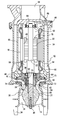
- the pump shown comprises a housing 12, generally cylindrical, housing a suction stage 14 and an electric motor 16.
- the latter comprises a stator 18 secured to the housing and a rotor 20 provided with a drive shaft 22 whose axis coincides with that of the suction stage.
- the shaft 22 is mechanically coupled to the suction stage 14 which mainly comprises an Archimedean screw drive unit, hereinafter referred to as the inductor 26.
- the suction stage is surmounted by a centrifugal wheel 28 , known in itself.
- a rectifier 30 whose fixed vanes 31 are integral with the casing is installed coaxially between the inductor 26 and the centrifugal wheel 28. Under normal operating conditions the pump is designed to be positioned at least approximately vertically and immersed in the fluid.
- the pumping inlet 35 is defined in the vicinity of this lower end 34.
- the inductor 26 the rectifier 30, the centrifugal wheel 28 and the electric motor 16 driving the shaft 22.
- This shaft and the rotating parts of the pump which are integral therewith are supported by two ball bearings , Coaxial and spaced apart on both sides of the engine, a first bearing 38, main, located between the suction stage 14 and the motor 16, more precisely just above the centrifugal wheel 28, and a second bearing 40, located above the engine.
- the inner cage is fixed to the shaft while the outer cage is slidably mounted in a bore of the housing 12 so that all of the rotating elements of the pump can move in the longitudinal direction of the housing. tree.
- Said first bearing 38 is installed in the center of a transverse wall 44 of the housing, which separates the suction stage of the engine.
- the stator of the electric motor is integral with an inner liner 46 of the housing, coaxial with the shaft, so that the air gap 48 of the motor, defined between the outside of the rotor and the inside of the stator, establishes a communication between a lower chamber 50 of said inner liner (extending between said first bearing and the lower end of the engine) and an upper chamber 52 of said inner liner extending between the engine and said second bearing.
- said inner liner is filled with the fluid to be pumped.
- An annular duct 54 communicating with the outlet 56 of the centrifugal wheel 28 extends around said inner liner 46 and opens at its upper part in a discharge duct 58 of the pumped fluid.
- a dynamic balancing system 60 defined by a double pumped fluid circulation circuit is arranged between the centrifugal wheel and the housing.
- This balancing system comprises a high pressure flow space 62 defined between the housing and a lower face of the centrifugal wheel and a low pressure flow space 64 defined between the housing (more particularly said transverse wall 44 in which is mounted said first bearing) and an upper face of the centrifugal wheel.
- the high pressure flow space 62 defined between said housing and said lower face extends annularly between the high pressure outlet 56 of the centrifugal wheel and the inlet 66, low pressure, of this same wheel.
- a first labyrinth seal 68 (or similar calibrated annular flow restriction) is arranged between the innermost radial end of this high pressure flow space and said low pressure inlet. The entry of this high-pressure flow space is located at the outlet of the centrifugal wheel, without flow restriction.
- the low pressure flow space 64 defined between said transverse wall 44 of the housing and said upper face of the centrifugal wheel extends annularly between a second labyrinth seal 70 (establishing a calibrated communication with the high pressure outlet of the centrifugal wheel ) and an annular passage 72 forming variable flow restriction, defined radially internally with respect to said second labyrinth seal 70.
- This annular passage is created between two coaxial annular ribs and facing one another, a rib 74 projecting from the upper face of the centrifugal wheel and a rib 76 projecting from the transverse face of the housing bearing said first bearing. .
- the annular passage constitutes a variable flow restriction because the shaft, to which the centrifugal wheel is attached, is slightly movable in its longitudinal direction, as indicated above.
- annular discharge space 78 is defined radially internally with respect to the annular passageway 72, i.e. between it and the shaft. It communicates with the inlet 66, low pressure, the centrifugal wheel by reinjection channels 80 made in this wheel. Thus, said annular discharge space is permanently at substantially the low pressure prevailing at the inlet of the centrifugal wheel.
- said second bearing 40 maintains the upper end of the shaft. It is installed in an axial cavity 84 extending upwards the upper chamber 52. At least one discharge duct 86 (returning to the reservoir in which the pump plunges) communicates with this cavity and thus with said upper chamber 52.
- the or each discharge duct is equipped with a flow calibration element 88.
- said second bearing 40 is therefore installed between the upper chamber and the or each discharge duct.
- the pressure in the latter is therefore almost equal to the high pressure at the exit of the centrifugal wheel.
- the housing of the first bearing 38 communicates with the annular discharge space 78 via a calibrated annular flow restriction seal 92.
- fluidic cooling circuits (using part of the pumped fluid) are independent of the double fluid circulation circuit of the axial balancing system defined above.
- the fluidic supply circuit of the balancing system consists essentially of the high pressure flow space 62 and the low pressure flow space 64, defined above.
- the annular discharge space 78 at low pressure does not intervene in the balancing system.
- the engine cooling circuit is established between the inlet ports 90 formed in the jacket and the flow restriction (s) 88 and therefore comprises the lower chamber 50, the air gap 48 of the engine, the upper chamber 52 (and the axial cavity 84) or the discharge duct (s) 86 and the flow restriction (s) 88.
- the fluid is reintroduced at the inlet of the pump.
- the cooling circuit of the first bearing 38 is supplied by the orifices 90 and comprises the lower chamber 50, the seal 92, the annular discharge space 78 and the reinjection channels 80 returning the fluid to the inlet of the centrifugal wheel.
- the cooling circuit of the second bearing 40 is the same as that of the electric motor 16.
- the cooling of the second bearing is less crucial than that of the first bearing and can therefore be combined with that of the electric motor.
Landscapes
- Engineering & Computer Science (AREA)
- Mechanical Engineering (AREA)
- General Engineering & Computer Science (AREA)
- Physics & Mathematics (AREA)
- Thermal Sciences (AREA)
- Structures Of Non-Positive Displacement Pumps (AREA)
- Control Of Non-Positive-Displacement Pumps (AREA)
Applications Claiming Priority (1)
| Application Number | Priority Date | Filing Date | Title |
|---|---|---|---|
| FR0653986A FR2906580B1 (fr) | 2006-09-28 | 2006-09-28 | Pompe a moteur electrique, immergee dans le fluide a pomper |
Publications (1)
| Publication Number | Publication Date |
|---|---|
| EP1908960A1 true EP1908960A1 (de) | 2008-04-09 |
Family
ID=37688389
Family Applications (1)
| Application Number | Title | Priority Date | Filing Date |
|---|---|---|---|
| EP07117499A Ceased EP1908960A1 (de) | 2006-09-28 | 2007-09-28 | Elektromotorpumpe, die in die zu pumpende Flüssigkeit eingetaucht ist |
Country Status (5)
| Country | Link |
|---|---|
| US (1) | US20080080988A1 (de) |
| EP (1) | EP1908960A1 (de) |
| JP (1) | JP2008082318A (de) |
| KR (1) | KR20080029772A (de) |
| FR (1) | FR2906580B1 (de) |
Cited By (3)
| Publication number | Priority date | Publication date | Assignee | Title |
|---|---|---|---|---|
| CN104389795A (zh) * | 2014-10-31 | 2015-03-04 | 湖州三井低温设备有限公司 | 一种lng潜液泵 |
| US9297386B2 (en) | 2010-09-13 | 2016-03-29 | Zenit International S.A. | Cooling systems for submersible pumps |
| CN111852897A (zh) * | 2020-07-10 | 2020-10-30 | 蓝添财 | 一种潜水泵扬程控制方法及其泵结构 |
Families Citing this family (10)
| Publication number | Priority date | Publication date | Assignee | Title |
|---|---|---|---|---|
| JP5248447B2 (ja) * | 2009-08-26 | 2013-07-31 | 日機装株式会社 | モータポンプ |
| CN101832275B (zh) * | 2010-04-07 | 2012-03-21 | 福建天工电机有限公司 | 一种水冷离心水泵 |
| KR101272684B1 (ko) * | 2011-11-15 | 2013-06-10 | 한국항공우주연구원 | 강제 순환로를 포함하는 베어링 냉각장치 및 상기 베어링 냉각장치를 구비하는 액체연료펌프 |
| KR101381403B1 (ko) * | 2012-09-24 | 2014-04-04 | 한국항공우주연구원 | 샤프트를 통한 누설 유체 순환 방식의 원심 펌프 |
| CN105041671A (zh) * | 2015-08-06 | 2015-11-11 | 三禾电器(福建)有限公司 | 一种实现智能调节、观测、统计流量的电泵 |
| ES2756199T3 (es) * | 2015-11-19 | 2020-04-27 | Grundfos Holding As | Bomba centrífuga multietapa con un émbolo de compensación de empuje axial, cuyos lados de presión y de aspiración están separados por un retén frontal |
| EP3171033A1 (de) * | 2015-11-19 | 2017-05-24 | Grundfos Holding A/S | Mehrstufige kreiselpumpe mit gehäuseöffnung zur wartung eines axialschub-kolbens |
| KR101812033B1 (ko) * | 2016-11-03 | 2018-01-25 | 뉴모텍(주) | 전이상태에서 발생하는 소음을 방지할 수 있는 온수 순환 펌프 |
| EP4229301A4 (de) | 2020-10-19 | 2025-02-19 | Milwaukee Electric Tool Corporation | Stiftpumpenanordnung |
| CN121127677A (zh) * | 2023-01-20 | 2025-12-12 | 第四电力公司 | 由脆性材料制成的循环泵 |
Citations (4)
| Publication number | Priority date | Publication date | Assignee | Title |
|---|---|---|---|---|
| US2887062A (en) * | 1954-07-01 | 1959-05-19 | Westinghouse Electric Corp | Motor pump unit |
| FR2032189A5 (de) * | 1969-02-21 | 1970-11-20 | Guinard Pompes | |
| US3652186A (en) * | 1970-05-25 | 1972-03-28 | Carter Co J C | Pressure lubricated, cooled and thrust balanced pump and motor unit |
| EP0740078A1 (de) * | 1995-03-03 | 1996-10-30 | Westinghouse Electric Corporation | Spaltrohrmotor-Umfülltauchpumpe |
Family Cites Families (4)
| Publication number | Priority date | Publication date | Assignee | Title |
|---|---|---|---|---|
| US3453964A (en) * | 1967-08-09 | 1969-07-08 | Air Reduction | Casing valve assembly |
| JPS58192997A (ja) * | 1982-05-07 | 1983-11-10 | Hitachi Ltd | 立形モ−タポンプ |
| JPH0668279B2 (ja) * | 1987-12-28 | 1994-08-31 | 日機装株式会社 | サブマージド型ポンプ |
| JP4300088B2 (ja) * | 2003-09-29 | 2009-07-22 | 日機装株式会社 | サブマージドポンプ |
-
2006
- 2006-09-28 FR FR0653986A patent/FR2906580B1/fr active Active
- 2006-10-13 JP JP2006279780A patent/JP2008082318A/ja not_active Withdrawn
- 2006-10-13 US US11/580,160 patent/US20080080988A1/en not_active Abandoned
-
2007
- 2007-07-19 KR KR1020070072207A patent/KR20080029772A/ko not_active Withdrawn
- 2007-09-28 EP EP07117499A patent/EP1908960A1/de not_active Ceased
Patent Citations (4)
| Publication number | Priority date | Publication date | Assignee | Title |
|---|---|---|---|---|
| US2887062A (en) * | 1954-07-01 | 1959-05-19 | Westinghouse Electric Corp | Motor pump unit |
| FR2032189A5 (de) * | 1969-02-21 | 1970-11-20 | Guinard Pompes | |
| US3652186A (en) * | 1970-05-25 | 1972-03-28 | Carter Co J C | Pressure lubricated, cooled and thrust balanced pump and motor unit |
| EP0740078A1 (de) * | 1995-03-03 | 1996-10-30 | Westinghouse Electric Corporation | Spaltrohrmotor-Umfülltauchpumpe |
Cited By (5)
| Publication number | Priority date | Publication date | Assignee | Title |
|---|---|---|---|---|
| US9297386B2 (en) | 2010-09-13 | 2016-03-29 | Zenit International S.A. | Cooling systems for submersible pumps |
| EP2616687B1 (de) * | 2010-09-13 | 2018-05-16 | Zenit International S.A. | Kühlsysteme für tauchpumpen |
| CN104389795A (zh) * | 2014-10-31 | 2015-03-04 | 湖州三井低温设备有限公司 | 一种lng潜液泵 |
| CN111852897A (zh) * | 2020-07-10 | 2020-10-30 | 蓝添财 | 一种潜水泵扬程控制方法及其泵结构 |
| CN111852897B (zh) * | 2020-07-10 | 2021-08-13 | 中山市伊赫亚家电实业有限公司 | 一种潜水泵扬程控制方法及其泵结构 |
Also Published As
| Publication number | Publication date |
|---|---|
| JP2008082318A (ja) | 2008-04-10 |
| FR2906580B1 (fr) | 2009-01-09 |
| KR20080029772A (ko) | 2008-04-03 |
| US20080080988A1 (en) | 2008-04-03 |
| FR2906580A1 (fr) | 2008-04-04 |
Similar Documents
| Publication | Publication Date | Title |
|---|---|---|
| EP1908960A1 (de) | Elektromotorpumpe, die in die zu pumpende Flüssigkeit eingetaucht ist | |
| CA2758175C (fr) | Moteur a turbine a gaz a double corps pourvu d ' un palier inter-arbres | |
| CA2564491C (fr) | Dispositif de ventilation de disques de turbine dans un moteur a turbine a gaz | |
| EP0368122A1 (de) | Mehrstufige Roots-Vakuumpumpe | |
| WO2004003347A1 (fr) | Circuits de ventilation de la turbine d'une turbomachine | |
| EP3430243B1 (de) | Turbostrahltriebwerk mit einer vereinfachten lagerschmierungsanordnung | |
| FR2672341A1 (fr) | Pompe a carburant a deux etages. | |
| FR2755479A1 (fr) | Pompe de circulation, notamment pour transferer du carburant d'un reservoir vers un moteur thermique | |
| FR2698667A1 (fr) | Pompe centrifuge à rouet ouvert. | |
| EP3443266B1 (de) | Verbesserte injektoren für eine gasturbinenbrennkammer | |
| FR2827640A1 (fr) | Systeme pour reduire la cavitation d'une pompe | |
| CH705213B1 (fr) | Pompe comprenant un système d'équilibrage axial. | |
| FR2806446A1 (fr) | Turbocompresseur | |
| EP1749977B1 (de) | Dichtungssystem des hinteren lagergehäuses eines strahltriebwerks | |
| FR2926327A1 (fr) | Moteur a turbine a gaz avec clapet de mise en communication de deux enceintes | |
| EP4127417B1 (de) | Fluggasturbinenaufbau welcher ein verbessertes schmiersystem eines ein gebläse antreibendes untersetzungsgetriebes umfasst | |
| FR3097907A1 (fr) | Contrôle actif du débit de refroidissement du compresseur haute pression | |
| FR2611818A1 (fr) | Pompe rotative a vide moleculaire du type a canal de gaede | |
| EP0469964B1 (de) | Turbopumpe zur gleichzeitigen Kompression von zwei Flüssigkeiten | |
| EP1473462B1 (de) | Patrone zum Zusammenbau eines Verdichters | |
| EP4277844B1 (de) | Lüfter mit variabler neigung | |
| WO2026082319A1 (fr) | Compresseur haute vitesse compartimente comprenant un systeme de refroidissement de la pivoterie dudit compresseur | |
| WO2026077713A1 (fr) | Désaérateur incurvé installé dans un reservoir d'huile pour turbomachine | |
| FR3145786A1 (fr) | Palier de roulement, cartouche de palier d’orientation, rotor d’helice et turbomachine correspondants | |
| FR3162831A1 (fr) | Dispositif de tourbillonnement axial pour chambre de combustion de turbomachine. |
Legal Events
| Date | Code | Title | Description |
|---|---|---|---|
| PUAI | Public reference made under article 153(3) epc to a published international application that has entered the european phase |
Free format text: ORIGINAL CODE: 0009012 |
|
| 17P | Request for examination filed |
Effective date: 20070928 |
|
| AK | Designated contracting states |
Kind code of ref document: A1 Designated state(s): AT BE BG CH CY CZ DE DK EE ES FI FR GB GR HU IE IS IT LI LT LU LV MC MT NL PL PT RO SE SI SK TR |
|
| AX | Request for extension of the european patent |
Extension state: AL BA HR MK RS |
|
| 17Q | First examination report despatched |
Effective date: 20081110 |
|
| AKX | Designation fees paid |
Designated state(s): CH FR GB LI |
|
| REG | Reference to a national code |
Ref country code: DE Ref legal event code: 8566 |
|
| STAA | Information on the status of an ep patent application or granted ep patent |
Free format text: STATUS: THE APPLICATION HAS BEEN REFUSED |
|
| 18R | Application refused |
Effective date: 20091116 |