EP1908670B1 - Gusset plate for connecting three profiles at an angle to each other for the cargo area superstructure of lorries - Google Patents
Gusset plate for connecting three profiles at an angle to each other for the cargo area superstructure of lorries Download PDFInfo
- Publication number
- EP1908670B1 EP1908670B1 EP07450173A EP07450173A EP1908670B1 EP 1908670 B1 EP1908670 B1 EP 1908670B1 EP 07450173 A EP07450173 A EP 07450173A EP 07450173 A EP07450173 A EP 07450173A EP 1908670 B1 EP1908670 B1 EP 1908670B1
- Authority
- EP
- European Patent Office
- Prior art keywords
- gusset plate
- supporting
- sections
- loading platform
- support
- Prior art date
- Legal status (The legal status is an assumption and is not a legal conclusion. Google has not performed a legal analysis and makes no representation as to the accuracy of the status listed.)
- Active
Links
Images
Classifications
-
- B—PERFORMING OPERATIONS; TRANSPORTING
- B62—LAND VEHICLES FOR TRAVELLING OTHERWISE THAN ON RAILS
- B62D—MOTOR VEHICLES; TRAILERS
- B62D33/00—Superstructures for load-carrying vehicles
-
- B—PERFORMING OPERATIONS; TRANSPORTING
- B62—LAND VEHICLES FOR TRAVELLING OTHERWISE THAN ON RAILS
- B62D—MOTOR VEHICLES; TRAILERS
- B62D27/00—Connections between superstructure or understructure sub-units
- B62D27/02—Connections between superstructure or understructure sub-units rigid
- B62D27/023—Assembly of structural joints
-
- B—PERFORMING OPERATIONS; TRANSPORTING
- B62—LAND VEHICLES FOR TRAVELLING OTHERWISE THAN ON RAILS
- B62D—MOTOR VEHICLES; TRAILERS
- B62D33/00—Superstructures for load-carrying vehicles
- B62D33/02—Platforms; Open load compartments
- B62D33/0222—Connecting elements between stanchions, e.g. roof supporting elements, stiffeners
Definitions
- the invention relates to a gusset plate for connecting three angularly disposed profiles of a cargo bed structure for trucks, wherein the gusset plate has an angle formed by two side parts angle profile for fastening, preferably for mechanical fastening, at a vertical forces of the bed structure in the cargo bed supporting profiles and a Kit for the self-construction of a loading area and a loading area construction.
- Cargo bed superstructures are used in particular for flatbed vehicles for the transport of long goods.
- a gusset plate of this kind is from the US 5,071,185 A1 known. This gusset plate serves as part of a fishing rod for hanging on-board boundaries for loading areas of trucks.
- a gusset plate which shows the preamble of claim 1, is out DE 27 28 450 known.
- Cargo bed superstructures for trucks e.g. Flatbed vehicles are usually designed as welded constructions.
- the disadvantage here is that a locksmith's workshop must be consulted for the preparation of such loading area construction, firstly to measure the loading area and secondly after completion of the loading area for its collection, as a shipping of such a loading area structure, which occupies a large volume, unprofitable and often also not possible.
- the object of the invention is to obviate these drawbacks and difficulties and has as its object the provision of a device which makes it possible to adapt loading area structures in width, length and height to the requirements in a simple manner, wherein it should be possible for an assembly of a loading area structure without carrying out welding work is possible.
- cargo bed superstructures of customers should be easy and inexpensive to produce even with the purchase of items.
- the gusset plate in extension of the two side parts side tabs for fastening, preferably mechanical fastening has approximately horizontally extending support profiles
- each of the side flaps is provided with a support tab for supporting the approximately horizontally extending support profiles.
- Such a gusset plate is integrally designed as a sheet metal part, whereby a particularly simple production is secured.
- a particular embodiment of the gusset plate according to which a particularly secure connection of the profiles is ensured characterized in that at least one side flap has a cover flap lying parallel to the support tab for U-shaped embracing a support profile, expediently directed a side part with a parallel to the other side part Support tab is provided for U-shaped embracing a support profile.
- a higher strength of a gusset plate is given when the side flaps merge rounded into the side panels.
- a preferred embodiment is characterized in that the side flaps are arranged on the side parts in unequal planes, ie offset in height.
- holes are already present in the gusset plate for the mechanical fastening of support or support profiles in the side parts and side flaps.
- a further preferred embodiment is characterized by a fastened to the outside of a side flap quick release whose headband projects beyond the top edge of the side flap.
- a set for self-construction of a cargo bed structure for trucks results from four identically designed gusset plates, so that such a loading area structure of four support profiles and four support profiles can be formed.
- such a set is characterized in that further foot parts are provided for the support profiles, which can be fastened to the loading surface, preferably mechanically fastened, floor panels and uprights of these, preferably a U-shaped cross-section having side parts for attachment, preferably mechanical attachment, the support profiles ,
- a preferred variant is characterized in that it comprises further gusset plates with preferably a U-profile forming side parts and only one of a side part of projecting side flap, preferably protruding from a support tab having, according to another variant, two or more a support profile U-shaped encompassing mounting hardware for mounting a rear window protection are provided.
- a bed structure preferably has four support profiles which project upwardly above the gussets, thereby securing cargo against slipping sideways.
- the gusset plates terminate with carrier profiles extending transversely of the truck, i.e., the gusset plates do not project beyond these carrier profiles in height.
- preferably supporting profiles extending in the longitudinal direction of the load vehicle are provided lower than carrying profiles extending transversely to the longitudinal direction of the load vehicle.
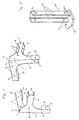
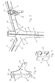
- Fig. 1 illustrates two mirror images of the same design gusset plates and Fig. 2 a foot part in oblique view.
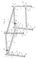
- Fig. 3 illustrates the arrangement of a gusset plate with a support and two support profiles, also in oblique view.
- the 4 and 5 show optional accessories in oblique view.
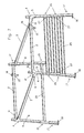
- the Fig. 6 and 7 illustrate a loading area construction using the gusset plates according to the invention and the accessories, again in an oblique view.
- Each gusset plate 4, 4 ' has two side parts 5, 6 facing each other at an angle 7, the angle 7, which these side parts 5, 6 enclose with one another, on the support profile 1, on which the gusset plate 4, 4' is to be mounted. is adapted, so that the two side parts 5, 6 abut well on the side surfaces of the support section 1.
- the side part 6 still has a support tab 8, which is provided such that the support profile 1 is not only U-shaped by the two side parts 5, 6, but also by the support tab 8 is included. Holes 9 provided in the side parts 5, 6 and in the support lug 8 make it possible to attach the support profile 1 to the gusset plate 4, 4 'by means of screw connections.
- each of the side flaps 10, 11 with a support tab 12, 13 for laying a support profile 2 or 3 is provided.
- the side flap 11 is provided with a cover flap 14, which is opposite to the support tab 12, so that the support profile 3 to be stored here is U-shaped of the support tab 12, the side flap 11 and the cover flap 14.
- Holes 9 in turn serve to connect this support section 3 in a simple manner by means of a screw connection with the gusset plate 4, 4 '.
- the second side flap 10 which is provided at the upper end of the gusset plate 4, 4 ', has a height which is not greater than the height of the bearing on the support tab 13 reaching support profile 2, so that the gusset plate 4 or 4'hhenfact this support profile 2 is not surmounted.
- holes 9 are provided, which serve to connect this support section 2 with the gusset plate 4 and 4 'by means of a screw connection in a simple manner.
- the transition of the side flaps 10, 11 to the side parts 5, 6 of the gusset plates 4, 4 ' is preferably rounded, whereby each gusset plate 4, 4' in addition to a good appearance also has an increased load capacity.
- the gusset plates 4, 4 ' are preferably integrally bent from a sheet, so that in the production of a gusset plate 4, 4' only punching and bending work - in addition to providing the holes - incurred, and no welding is necessary.
- the gusset plates 4, 4 ' are formed from as stable a sheet as possible, e.g. an aluminum alloy or a steel sheet, which may be coated, if it is not stainless.
- the gusset plates 4, 4 ' are designed mirror images of the same, that an approximately rectangular frame can be formed by the support sections 2, 3.
- the support profiles 1 project beyond the gusset plates 4, 4 ', and two support profiles 2 extending in the transverse direction to the loading area of a freight vehicle are provided in height above the carrying profiles 3 extending in the longitudinal direction of the loading area of the load vehicle, which results in the arrangement of the side straps 10 , 11 of the gusset plates 4, 4 'is taken into account.
- a transport device for long goods snap fasteners 15 may be provided, which are attached either to a support section 2 or to a gusset plate 4 ', wherein the headband 16 of Snap fasteners 15 project beyond the upper edge of the transversely extending support profiles 2.
- the longitudinally extending support profiles 3 can of course also be used to support loads, but they are used primarily for stiffening or for supporting the transversely extending support profiles 2 and the support profiles.
- 1 Fig. 6 indicates that the support profiles 1 do not extend exactly vertically, but are provided slightly inclined to each other, which is also taken into account in the design of the gussets 4, 4 '.
- Fig. 2 For attaching the loading area structure to a loading area serve in Fig. 2 shown foot parts 17, which are formed by a bottom plate 18 and thereof towering side members 19. Both the bottom plate 18 and the side parts 19 in turn have holes 9 for mechanical fastening to the loading area or to the support profiles 1 by means of screw connections.
- the upwardly extending side parts 19 of the foot part 17 suitably comprise a support profile 1 U-shaped, so that a particularly good hold of the support profile 1 is given.
- a bore 9 is also provided below the to be provided support profile 1, which, when the loading space structure is mounted on the truck is covered by the support profile 1, so that it is not readily possible, the loading area of the loading surface by releasing the visible Remove screw connections. Namely, it would have to be previously additionally removed the support sections 1 of the foot parts 17, which is a considerable expense.
- a further support profile 20 is provided, which is expediently fastened at a height to the support profiles 1, in which the upper edge of a rear side wall of a load vehicle is surmounted by this support profile 20 and on this support section 20 also long goods can be launched without the opening and closing of the side wall is obstructed.
- the measures provided for the support section 20 fasteners are in Fig. 4 shown; it is further gusset plates 21 with a U-profile forming side parts 22, 23 with only one of a side part 23 projecting side flap 24, to which also by means of screw the support profile can be attached.
- the side parts 22, 23 comprise the support profile 1U-shaped and are attached to this also by means of screw connections.
- This gusset plate can also be attached to the Side tab 24 have a support tab similar to the support tab 13 for the support section 20.
- a support profile 1 U-shaped embracing fasteners 26 are provided, the attachment to the support profiles 1 also by means of a screw can be realized.
- These fasteners 26 are further provided with adapted to the profile of the rear window protection 25 mounting tabs 27, where the rear window guard 25, as in Fig. 7 illustrated, can be mounted in a simple manner.
- the invention enables the simple assembly of a bed structure, which is adaptable to the loading area in width, length and height. It only need the support sections 1 and the support sections 2, 3 are cut to length according to the desired length, the gussets 4, 4 'can then be connected as desired with the profiles 1, 2, 3.
- the already existing holes 9 and the support tabs 12, 13 allow a very quick and easy installation of the loading area structure, with no welding is necessary, so also eliminates welding pre-and post-work.
- a loading area structure can be sent in a simple manner and space-saving in not yet assembled state, often only the knots 4, 4 'and the foot parts 17 and optionally accessories 21, 26 must be sent for the assembly of another support section 20 or a rear window protection 25, Especially since many companies that need a loading area structure, even have corresponding profiles 1, 2, 3.
Landscapes
- Engineering & Computer Science (AREA)
- Chemical & Material Sciences (AREA)
- Combustion & Propulsion (AREA)
- Transportation (AREA)
- Mechanical Engineering (AREA)
- Body Structure For Vehicles (AREA)
- Auxiliary Methods And Devices For Loading And Unloading (AREA)
- Vehicle Step Arrangements And Article Storage (AREA)
Description
Die Erfindung betrifft ein Knotenblech zum Verbinden von drei im Winkel zueinander stehenden Profilen eines Ladeflächenaufbaus für Lastfahrzeuge, wobei das Knotenblech ein von zwei Seitenteilen gebildetes Winkelprofil zum Befestigen, vorzugsweise zum mechanischen Befestigen, an einem die Vertikalkräfte des Ladeflächenaufbaus in die Ladefläche leitenden Stützprofilen aufweist sowie ein Set zum Selbstbau eines Ladeflächenaufbaus und einen Ladeflächenaufbau. Ladeflächenaufbauten werden insbesondere für Pritschenfahrzeuge zum Transport von Langgütern eingesetzt.The invention relates to a gusset plate for connecting three angularly disposed profiles of a cargo bed structure for trucks, wherein the gusset plate has an angle formed by two side parts angle profile for fastening, preferably for mechanical fastening, at a vertical forces of the bed structure in the cargo bed supporting profiles and a Kit for the self-construction of a loading area and a loading area construction. Cargo bed superstructures are used in particular for flatbed vehicles for the transport of long goods.
Ein Knotenblech dieser Art ist aus der
Ein Knotenblech, welches den Oberbegriff des Anspruchs 1 zeigt, ist aus
Ladeflächenaufbauten für Lastfahrzeuge, wie z.B. Pritschenfahrzeuge, sind in der Regel als Schweißkonstruktionen ausgebildet. Nachteilig ist hierbei, dass für die Herstellung eines solchen Ladeflächenaufbaus eine Schlosserwerkstatt aufgesucht werden muss, und zwar erstens zum Vermessen der Ladefläche und zweitens nach Fertigstellung des Ladeflächenaufbaus zu dessen Abholung, da ein Versenden eines solchen Ladeflächenaufbaus, der ein großes Volumen einnimmt, unrentabel und oftmals auch gar nicht möglich ist.Cargo bed superstructures for trucks, e.g. Flatbed vehicles are usually designed as welded constructions. The disadvantage here is that a locksmith's workshop must be consulted for the preparation of such loading area construction, firstly to measure the loading area and secondly after completion of the loading area for its collection, as a shipping of such a loading area structure, which occupies a large volume, unprofitable and often also not possible.
Die Erfindung bezweckt die Vermeidung dieser Nachteile und Schwierigkeiten und stellt sich die Aufgabe, eine Einrichtung zu schaffen, die es ermöglicht, Ladeflächenaufbauten in Breite, Länge und Höhe in einfacher Weise an die Erfordernisse anzupassen, wobei es möglich sein soll, dass ein Zusammenbau eines Ladeflächenaufbaus ohne die Durchführung von Schweißarbeiten möglich ist. Insbesondere sollen Ladeflächenaufbauten von Kunden selbst unter Zukauf der Einzelteile einfach und kostengünstig herstellbar sein.The object of the invention is to obviate these drawbacks and difficulties and has as its object the provision of a device which makes it possible to adapt loading area structures in width, length and height to the requirements in a simple manner, wherein it should be possible for an assembly of a loading area structure without carrying out welding work is possible. In particular, cargo bed superstructures of customers should be easy and inexpensive to produce even with the purchase of items.
Diese Aufgabe wird dadurch gelöst, dass das Knotenblech in Verlängerung der beiden Seitenteile Seitenlaschen zum Befestigen, vorzugsweise mechanischen Befestigen, von sich etwa horizontal erstreckenden Tragprofilen aufweist, wobei jede der Seitenlaschen mit einer Auflagelasche zur Auflage der sich etwa horizontal erstreckenden Tragprofile versehen ist.This object is achieved in that the gusset plate in extension of the two side parts side tabs for fastening, preferably mechanical fastening, has approximately horizontally extending support profiles, each of the side flaps is provided with a support tab for supporting the approximately horizontally extending support profiles.
Ein solches Knotenblech ist einstückig als Blechformteil gestaltet, wodurch eine besonders einfache Herstellung gesichert ist.Such a gusset plate is integrally designed as a sheet metal part, whereby a particularly simple production is secured.
Eine besondere Ausführungsform des Knotenblechs gemäß der eine besonders sichere Verbindung der Profile gewährleistet ist, ist dadurch gekennzeichnet, dass mindestens eine Seitenlasche eine zur Auflagelasche parallel liegende Decklasche zum U-förmigen Umfassen eines Tragprofils aufweist, wobei zweckmäßig ein Seitenteil mit einer parallel zum anderen Seitenteil gerichteten Stützlasche zum U-förmigen Umfassen eines Stützprofils versehen ist.A particular embodiment of the gusset plate according to which a particularly secure connection of the profiles is ensured, characterized in that at least one side flap has a cover flap lying parallel to the support tab for U-shaped embracing a support profile, expediently directed a side part with a parallel to the other side part Support tab is provided for U-shaped embracing a support profile.
Eine höhere Festigkeit eines Knotenblechs ist dann gegeben, wenn die Seitenlaschen in die Seitenteile abgerundet übergehen.A higher strength of a gusset plate is given when the side flaps merge rounded into the side panels.
Eine bevorzugte Ausführungsform ist dadurch gekennzeichnet, dass die Seitenlaschen an den Seitenteilen in ungleichen Ebenen, d.h. höhenversetzt, angeordnet sind.
Vorzugsweise sind in dem Knotenblech bereits zum mechanischen Befestigen von Stütz- oder Tragprofilen in den Seitenteilen und Seitenlaschen Bohrungen vorhanden.A preferred embodiment is characterized in that the side flaps are arranged on the side parts in unequal planes, ie offset in height.
Preferably, holes are already present in the gusset plate for the mechanical fastening of support or support profiles in the side parts and side flaps.
Eine weitere bevorzugte Ausführungsform ist gekennzeichnet durch einen an der Außenseite einer Seitenlasche befestigten Schnellverschluss, dessen Haltebügel die Oberkante der Seitenlasche überragt.A further preferred embodiment is characterized by a fastened to the outside of a side flap quick release whose headband projects beyond the top edge of the side flap.
Ein Set zum Selbstbau eines Ladeflächenaufbaus für Lastfahrzeuge ergibt sich durch vier gegengleich gestaltete Knotenbleche, sodass ein solcher Ladeflächenaufbau von vier Stützprofilen und vier Tragprofilen gebildet werden kann.A set for self-construction of a cargo bed structure for trucks results from four identically designed gusset plates, so that such a loading area structure of four support profiles and four support profiles can be formed.
Vorzugsweise ist ein solches Set dadurch gekennzeichent, dass weiters Fußteile für die Stützprofile vorgesehen sind, die an der Ladefläche befestigbare, vorzugsweise mechanisch befestigbare, Bodenplatten und von diesen aufragende, vorzugsweise einen U-Querschnitt aufweisende Seitenteile zur Befestigung, vorzugsweise mechanischen Befestigung, der Stützprofile aufweist.Preferably, such a set is characterized in that further foot parts are provided for the support profiles, which can be fastened to the loading surface, preferably mechanically fastened, floor panels and uprights of these, preferably a U-shaped cross-section having side parts for attachment, preferably mechanical attachment, the support profiles ,
Eine bevorzugte Variante ist dadurch gekennzeichnet, dass es weitere Knotenbleche mit vorzugsweise ein U-Profil bildenden Seitenteilen und nur einer von einem Seitenteil auskragenden Seitenlasche, von der vorzugsweise eine Auflagelasche auskragt, aufweist, wobei gemäß einer weiteren Variante zwei oder mehrere ein Stützprofil U-förmig umgreifende Befestigungsteile zur Montage eines Heckscheibenschutzes vorgesehen sind.A preferred variant is characterized in that it comprises further gusset plates with preferably a U-profile forming side parts and only one of a side part of projecting side flap, preferably protruding from a support tab having, according to another variant, two or more a support profile U-shaped encompassing mounting hardware for mounting a rear window protection are provided.
Ein Ladeflächenaufbau weist vorzugsweise vier Stützprofile auf, die über die Knotenbleche nach oben ragen, wodurch Ladegut gegen seitliches Abrutschen gesichert ist.A bed structure preferably has four support profiles which project upwardly above the gussets, thereby securing cargo against slipping sideways.
Vorzugsweise enden die Knotenbleche mit sich in Querrichtung zum Lastfahrzeug erstreckenden Tragprofilen, d.h., dass die Knotenbleche diese Tragprofile höhenmäßig nicht überragen.Preferably, the gusset plates terminate with carrier profiles extending transversely of the truck, i.e., the gusset plates do not project beyond these carrier profiles in height.
Weiters sind zwecks einfacher Beladung des Ladeflächenaufbaus mit einem Gabelstapler vorzugsweise sich in Längsrichtung des Lastfahrzeuges erstreckende Tragprofile tiefer vorgesehen als sich quer zur Längsrichtung des Lastfahrzeugs erstreckende Tragprofile.Furthermore, for the purpose of simple loading of the loading area structure with a forklift truck, preferably supporting profiles extending in the longitudinal direction of the load vehicle are provided lower than carrying profiles extending transversely to the longitudinal direction of the load vehicle.
Die Erfindung ist nachfolgend anhand eines in der Zeichnung dargestellten Ausführungsbeispiels näher erläutert.
Um einen Ladeflächenaufbau, wie er in
Jedes Knotenblech 4, 4' weist zwei im Winkel 7 zueinander gerichtete Seitenteile 5, 6 auf, wobei der Winkel 7, den diese Seitenteile 5, 6 miteinander einschließen, an das Stützprofil 1, an dem das Knotenblech 4, 4' zu montieren ist, angepasst ist, sodass die beiden Seitenteile 5, 6 an den Seitenflächen des Stützprofils 1 gut anliegen. Der Seitenteil 6 weist noch eine Stützlasche 8 auf, die derart vorgesehen ist, dass das Stützprofil 1 nicht nur von den beiden Seitenteilen 5, 6, sondern zusätzlich auch von der Stützlasche 8 U-förmig umfasst ist. In den Seitenteilen 5, 6 sowie in der Stützlasche 8 vorgesehene Bohrungen 9 ermöglichen das Befestigen des Stützprofils 1 an dem Knotenblech 4, 4' mittels Schraubverbindungen.Each
Von den Seitenteilen 5, 6 erstrecken sich Seitenlaschen 10, 11 in etwa rechtwinkelig zu der von den Seitenteilen gebildeten Winkelkante K und in der Ebene der Seitenteile 5, 6, wobei jede der Seitenlaschen 10, 11 mit einer Auflagelasche 12, 13 zum Auflegen eines Tragprofils 2 bzw. 3 versehen ist. Die Seitenlasche 11 ist mit einer Decklasche 14, die der Auflagelasche 12 gegenüberliegt, versehen, sodass das hier aufzulagernde Tragprofil 3 U-förmig von der Auflagelasche 12, der Seitenlasche 11 und der Decklasche 14 umfasst ist. Bohrungen 9 dienen wiederum dazu, dieses Tragprofil 3 in einfacher Weise mittels einer Schraubverbindung mit dem Knotenblech 4, 4' zu verbinden.Of the
Die zweite Seitenlasche 10, die am oberen Ende des Knotenbleches 4, 4' vorgesehen ist, weist eine Höhe auf, die nicht größer ist als die Höhe des auf der Auflagelasche 13 zur Anlage gelangenden Tragprofils 2, sodass das Knotenblech 4 bzw. 4'höhenmäßig dieses Tragprofil 2 nicht überragt. Auch hier sind wiederum Bohrungen 9 vorgesehen, die dazu dienen, dieses Tragprofil 2 mit dem Knotenblech 4 bzw. 4' mittels einer Schraubverbindung in einfacher Weise zu verbinden.The second side flap 10, which is provided at the upper end of the
Der Übergang der Seitenlaschen 10, 11 zu den Seitenteilen 5, 6 der Knotenbleche 4, 4' ist vorzugsweise abgerundet gestaltet, wodurch jedes Knotenblech 4, 4' neben einer guten Optik auch eine erhöhte Tragkraft aufweist. Die Knotenbleche 4, 4' sind vorzugsweise einstückig aus einem Blech gebogen, sodass bei der Herstellung eines Knotenblechs 4, 4' lediglich Stanz- und Biegearbeiten - neben dem Vorsehen der Bohrungen - anfallen, und keine Schweißarbeiten notwendig sind. Die Knotenbleche 4, 4' sind aus einem möglichst stabilen Blech gebildet, wie z.B. einer Aluminiumlegierung oder aus einem Stahlblech, das gegebenenfalls, sofern es nicht rostfrei ist, beschichtet ist.The transition of the side flaps 10, 11 to the
Wie insbesondere aus
Die sich in Längsrichtung erstreckenden Tragprofile 3 können selbstverständlich auch zur Auflage von Lasten verwendet werden, sie dienen jedoch in erster Linie zur Aussteifung bzw. zur Abstützung der sich in Querrichtung erstreckenden Tragprofile 2 und der Stützprofile 1.
Zum Befestigen des Ladeflächenaufbaus an einer Ladefläche dienen in
Wie aus
Zur Befestigung eines Heckscheibenschutzes 25 an dem Ladeflächenaufbau 1 sind ein Stützprofil 1 U-förmig umgreifende Befestigungsteile 26 vorgesehen, deren Befestigung an den Stützprofilen 1 ebenfalls mittels einer Schraubverbindung verwirklichbar ist. Diese Befestigungsteile 26 sind weiters mit an das Profil des Heckscheibenschutzes 25 angepasste Montagelaschen 27 vorgesehen, an denen der Heckscheibenschutz 25, wie in
Die Erfindung ermöglicht den einfachen Zusammenbau eines Ladeflächenaufbaus, wobei dieser in Breite, Länge und Höhe an die Ladefläche adaptierbar ist. Es müssen lediglich die Stützprofile 1 und die Tragprofile 2, 3 entsprechend der gewünschten Länge abgelängt werden, die Knotenbleche 4, 4' können dann ganz nach Wunsch mit den Profilen 1, 2, 3 verbunden werden. Die bereits vorhanden Bohrungen 9 sowie die Auflagelaschen 12, 13 ermöglichen eine sehr rasche und einfache Montage des Ladeflächenaufbaus, wobei keinerlei Schweißarbeiten notwendig sind, sodass auch Schweißvor- und -nacharbeiten entfallen. Ein Ladeflächenaufbau kann in einfacher Weise und platzsparend in noch nicht zusammengebautem Zustand verschickt werden, wobei oftmals nur die Knotenbelche 4, 4' und die Fußteile 17 sowie gegebenenfalls Zubehörteile 21, 26 für die Montage eines weiteren Tragprofils 20 oder eines Heckscheibenschutzes 25 versendet werden müssen, zumal viele Betriebe, die einen Ladeflächenaufbau benötigen, selbst über entsprechende Profile 1, 2, 3 verfügen.The invention enables the simple assembly of a bed structure, which is adaptable to the loading area in width, length and height. It only need the
Claims (14)
- A gusset plate (4, 4') for connecting three sections (1, 2, 3), positioned at an angle to each other, of a loading platform arrangement for trucks, wherein the gusset plate (4, 4') has an angle section formed by two side parts (5, 6) having an angle edge (K) formed by one of the side parts (5, 6) for fastening, preferably mechanical fastening, to a supporting section (1) transmitting the vertical forces of the loading platform arrangement into the loading platform and wherein the gusset plate (4, 4') in extension of the two side parts (5, 6) has lateral splices (10, 11) for fastening, preferably mechanical fastening, of approximately horizontally extending girder sections (2, 3), characterized in that the gusset plate (4, 4') is formed integrally of a sheet metal part and wherein each of the splices (10, 11) is provided with a support splice (12, 13) for supporting the horizontally extending girder sections (2, 3).
- A gusset plate (4, 4') according to claim 1, characterized in that at least one lateral splice (11) has a cover splice (14) in parallel to the support splice (12) for embracing a girder section (3) in a U-form.
- A gusset plate (4, 4') according to claim 1 or 2, characterized in that a side part (6) is provided with a supporting splice (8) in parallel to another side part (5) for embracing a supporting section (1) in a U-form.
- A gusset plate (4, 4') according to any of claims 1 to 3, characterized in that the lateral splices (10, 11) merge into the side parts (5, 6) in a rounded-off form.
- A gusset plate (4, 4') according to any of claims 1 to 4, characterized in that the lateral splices (10, 11) are arranged at the side parts (5, 6) in different planes, this is, offset in height.
- A gusset plate (4, 4') according to any of claims 1 to 5, characterized in that there are provided bores (9) in the side parts (5, 6) and lateral splices (10, 11) for the mechanical fastening of supporting and/or girder sections.
- A gusset plate (4, 4') according to any of claims 1 to 6, characterized by a quick release fastener (15) fastened to the external surface of a lateral splice (10), wherein the retaining bracket (16) of which projects beyond the upper edge of the lateral splice (10).
- A set for the do-it-yourself assembly of a loading platform arrangement for trucks using four gusset plates (4, 4') of opposite forms according to any of claims 1 to 7 for the assembly of a loading platform arrangement formed by four supporting sections (1) and four girder sections (2, 3).
- A set according to claim 8, characterized in that there are further provided stand supports (17) for the supporting sections (1), which have base plates (18) that may be fastened to the loading platform, preferably mechanically fastened, and side parts (19) extending from these, preferably having a U-shaped cross-section, for fastening, preferably mechanical fastening, of the supporting sections (1).
- A set according to claim 8 or 9, characterized in that it includes further gusset plates (21) with side parts (22, 23) preferably forming a U-section and a lateral splice (24) projecting from only one side part, from which preferably a support splice projects.
- A set according to any of claims 8 to 10, characterized by two or several fastening parts (26) embracing a supporting section (1) preferably in a U-form for mounting a rear windows protection (25).
- A loading platform arrangement, formed with a set according to any of claims 8 to 11, characterized by four supporting sections (1), which project upwards beyond the gusset plates (4, 4').
- A loading platform arrangement according to claim 12, characterized in that the gusset plates (4, 4') end in their heights in girder sections (2) extending in the transversal direction to the truck, this is, not exceeding height thereof.
- A loading platform arrangement according to claim 12 or 13, characterized in that girder sections (3) are provided in the longitudinal direction of the truck in a deeper height than girder sections (2) extending transversally to the longitudinal direction of the truck.
Applications Claiming Priority (1)
| Application Number | Priority Date | Filing Date | Title |
|---|---|---|---|
| AT0166506A AT503797B1 (en) | 2006-10-04 | 2006-10-04 | Corner plate for connecting three profiles, has angle profile formed by two side parts for mechanical fixing, and has side brackets in extension of two side parts |
Publications (3)
| Publication Number | Publication Date |
|---|---|
| EP1908670A2 EP1908670A2 (en) | 2008-04-09 |
| EP1908670A3 EP1908670A3 (en) | 2008-12-31 |
| EP1908670B1 true EP1908670B1 (en) | 2012-02-15 |
Family
ID=38656475
Family Applications (1)
| Application Number | Title | Priority Date | Filing Date |
|---|---|---|---|
| EP07450173A Active EP1908670B1 (en) | 2006-10-04 | 2007-10-04 | Gusset plate for connecting three profiles at an angle to each other for the cargo area superstructure of lorries |
Country Status (2)
| Country | Link |
|---|---|
| EP (1) | EP1908670B1 (en) |
| AT (2) | AT503797B1 (en) |
Cited By (1)
| Publication number | Priority date | Publication date | Assignee | Title |
|---|---|---|---|---|
| WO2025207070A1 (en) * | 2024-03-28 | 2025-10-02 | Tirsan Treyler Sanayi̇ Ve Ti̇caret Anoni̇m Şi̇rketi̇ | Monolithic body front corner mounting bracket with front position lamp mounting feature for trailer vehicles |
Families Citing this family (3)
| Publication number | Priority date | Publication date | Assignee | Title |
|---|---|---|---|---|
| DE102013002659A1 (en) * | 2013-02-15 | 2014-08-21 | Man Truck & Bus Ag | Frame structure for the construction of a commercial vehicle |
| CN106143650B (en) * | 2016-07-29 | 2018-09-04 | 北京汽车研究总院有限公司 | A kind of the angle connecting board structure and automobile of automobile |
| US11130524B2 (en) * | 2019-10-25 | 2021-09-28 | Caterpillar Inc. | Space frame center upper frame connection |
Family Cites Families (6)
| Publication number | Priority date | Publication date | Assignee | Title |
|---|---|---|---|---|
| US1629278A (en) * | 1925-04-27 | 1927-05-17 | Heintz Mfg Co | Post connection for vehicle bodies |
| US2080764A (en) * | 1936-11-05 | 1937-05-18 | Wilbur F Crawford | Vehicle bow support |
| DE2728450C2 (en) * | 1977-06-24 | 1986-04-30 | Wackenhut, Ernst, 7270 Nagold | Flat frame, especially for trucks |
| AU517487B2 (en) * | 1979-01-23 | 1981-08-06 | Whitlock, C.F. | Freight handling system |
| US5071185A (en) * | 1990-01-29 | 1991-12-10 | Schiele Jim D | Truck bed enclosure |
| AU7458098A (en) * | 1998-06-01 | 1999-12-20 | Abb Daimler-Benz Transportation, S.A. | Connecting element for structures for railway passenger vehicles |
-
2006
- 2006-10-04 AT AT0166506A patent/AT503797B1/en active
-
2007
- 2007-10-04 AT AT07450173T patent/ATE545570T1/en active
- 2007-10-04 EP EP07450173A patent/EP1908670B1/en active Active
Cited By (1)
| Publication number | Priority date | Publication date | Assignee | Title |
|---|---|---|---|---|
| WO2025207070A1 (en) * | 2024-03-28 | 2025-10-02 | Tirsan Treyler Sanayi̇ Ve Ti̇caret Anoni̇m Şi̇rketi̇ | Monolithic body front corner mounting bracket with front position lamp mounting feature for trailer vehicles |
Also Published As
| Publication number | Publication date |
|---|---|
| EP1908670A2 (en) | 2008-04-09 |
| ATE545570T1 (en) | 2012-03-15 |
| EP1908670A3 (en) | 2008-12-31 |
| AT503797A4 (en) | 2008-01-15 |
| AT503797B1 (en) | 2008-01-15 |
Similar Documents
| Publication | Publication Date | Title |
|---|---|---|
| DE2945550A1 (en) | LOAD CARRIER | |
| DE29800368U1 (en) | Screwed subframe | |
| EP1908670B1 (en) | Gusset plate for connecting three profiles at an angle to each other for the cargo area superstructure of lorries | |
| EP3882109B1 (en) | Outer frame profile for an outer frame for a commercial vehicle | |
| EP3037325B1 (en) | Distortion resistant and easily installed mounting frame for a load carrying vehicle | |
| DE102011115552A1 (en) | folding shelf | |
| EP2420406A1 (en) | Device for securing loads on a load surface of a vehicle structure | |
| DE102019116048A1 (en) | Shelf system and load securing device | |
| EP2682303B1 (en) | Extruded profile and vehicle | |
| EP1826101A2 (en) | Superstructure for a camper van | |
| EP3428086A1 (en) | System for transporting and/or storing transportable fence elements | |
| EP0590278B1 (en) | Show case | |
| DE10013239A1 (en) | Trailer trailer | |
| EP3348455B1 (en) | Support structure for a non-driven commercial vehicle | |
| DE19706493A1 (en) | Goods vehicle with additional upper load platforms | |
| DE2728963C3 (en) | Stake for trucks and trailers | |
| DE20009676U1 (en) | Post for commercial vehicles | |
| DE10036791B4 (en) | Car with a support structure made of composite lightweight panels | |
| DE20220363U1 (en) | Industrial truck has at least one add-on item such as headlamp fastened on tubular frame of driver's cab by means of clamping pieces which at least partially grip round hollow profile cross section of frame member | |
| DE3812506A1 (en) | Tarpaulin frame, in particular for lorries and trailers | |
| DE202021004415U1 (en) | Rear carrier | |
| EP1092613A2 (en) | Exterior frame member for a vehicle | |
| DE102005039355B4 (en) | Apparatus and method for attaching swap bodies to carrier vehicles | |
| DE102023101517B4 (en) | Two-part protective roof cell for a vehicle | |
| DE202018104554U1 (en) | Detachable fastening arrangement of a roof rail on the roof of a motor vehicle |
Legal Events
| Date | Code | Title | Description |
|---|---|---|---|
| PUAI | Public reference made under article 153(3) epc to a published international application that has entered the european phase |
Free format text: ORIGINAL CODE: 0009012 |
|
| AK | Designated contracting states |
Kind code of ref document: A2 Designated state(s): AT BE BG CH CY CZ DE DK EE ES FI FR GB GR HU IE IS IT LI LT LU LV MC MT NL PL PT RO SE SI SK TR |
|
| AX | Request for extension of the european patent |
Extension state: AL BA HR MK RS |
|
| PUAL | Search report despatched |
Free format text: ORIGINAL CODE: 0009013 |
|
| AK | Designated contracting states |
Kind code of ref document: A3 Designated state(s): AT BE BG CH CY CZ DE DK EE ES FI FR GB GR HU IE IS IT LI LT LU LV MC MT NL PL PT RO SE SI SK TR |
|
| AX | Request for extension of the european patent |
Extension state: AL BA HR MK RS |
|
| 17P | Request for examination filed |
Effective date: 20090227 |
|
| 17Q | First examination report despatched |
Effective date: 20090408 |
|
| AKX | Designation fees paid |
Designated state(s): AT BE BG CH CY CZ DE DK EE ES FI FR GB GR HU IE IS IT LI LT LU LV MC MT NL PL PT RO SE SI SK TR |
|
| GRAP | Despatch of communication of intention to grant a patent |
Free format text: ORIGINAL CODE: EPIDOSNIGR1 |
|
| GRAS | Grant fee paid |
Free format text: ORIGINAL CODE: EPIDOSNIGR3 |
|
| GRAA | (expected) grant |
Free format text: ORIGINAL CODE: 0009210 |
|
| AK | Designated contracting states |
Kind code of ref document: B1 Designated state(s): AT BE BG CH CY CZ DE DK EE ES FI FR GB GR HU IE IS IT LI LT LU LV MC MT NL PL PT RO SE SI SK TR |
|
| REG | Reference to a national code |
Ref country code: CH Ref legal event code: EP Ref country code: GB Ref legal event code: FG4D Free format text: NOT ENGLISH |
|
| REG | Reference to a national code |
Ref country code: IE Ref legal event code: FG4D Free format text: LANGUAGE OF EP DOCUMENT: GERMAN |
|
| REG | Reference to a national code |
Ref country code: AT Ref legal event code: REF Ref document number: 545570 Country of ref document: AT Kind code of ref document: T Effective date: 20120315 |
|
| REG | Reference to a national code |
Ref country code: CH Ref legal event code: NV Representative=s name: BRAUNPAT BRAUN EDER AG |
|
| REG | Reference to a national code |
Ref country code: DE Ref legal event code: R096 Ref document number: 502007009277 Country of ref document: DE Effective date: 20120412 |
|
| REG | Reference to a national code |
Ref country code: NL Ref legal event code: VDEP Effective date: 20120215 |
|
| LTIE | Lt: invalidation of european patent or patent extension |
Effective date: 20120215 |
|
| PG25 | Lapsed in a contracting state [announced via postgrant information from national office to epo] |
Ref country code: NL Free format text: LAPSE BECAUSE OF FAILURE TO SUBMIT A TRANSLATION OF THE DESCRIPTION OR TO PAY THE FEE WITHIN THE PRESCRIBED TIME-LIMIT Effective date: 20120215 Ref country code: IS Free format text: LAPSE BECAUSE OF FAILURE TO SUBMIT A TRANSLATION OF THE DESCRIPTION OR TO PAY THE FEE WITHIN THE PRESCRIBED TIME-LIMIT Effective date: 20120615 Ref country code: LT Free format text: LAPSE BECAUSE OF FAILURE TO SUBMIT A TRANSLATION OF THE DESCRIPTION OR TO PAY THE FEE WITHIN THE PRESCRIBED TIME-LIMIT Effective date: 20120215 |
|
| PG25 | Lapsed in a contracting state [announced via postgrant information from national office to epo] |
Ref country code: FI Free format text: LAPSE BECAUSE OF FAILURE TO SUBMIT A TRANSLATION OF THE DESCRIPTION OR TO PAY THE FEE WITHIN THE PRESCRIBED TIME-LIMIT Effective date: 20120215 Ref country code: LV Free format text: LAPSE BECAUSE OF FAILURE TO SUBMIT A TRANSLATION OF THE DESCRIPTION OR TO PAY THE FEE WITHIN THE PRESCRIBED TIME-LIMIT Effective date: 20120215 Ref country code: PL Free format text: LAPSE BECAUSE OF FAILURE TO SUBMIT A TRANSLATION OF THE DESCRIPTION OR TO PAY THE FEE WITHIN THE PRESCRIBED TIME-LIMIT Effective date: 20120215 Ref country code: GR Free format text: LAPSE BECAUSE OF FAILURE TO SUBMIT A TRANSLATION OF THE DESCRIPTION OR TO PAY THE FEE WITHIN THE PRESCRIBED TIME-LIMIT Effective date: 20120516 Ref country code: PT Free format text: LAPSE BECAUSE OF FAILURE TO SUBMIT A TRANSLATION OF THE DESCRIPTION OR TO PAY THE FEE WITHIN THE PRESCRIBED TIME-LIMIT Effective date: 20120615 |
|
| REG | Reference to a national code |
Ref country code: IE Ref legal event code: FD4D |
|
| PG25 | Lapsed in a contracting state [announced via postgrant information from national office to epo] |
Ref country code: CY Free format text: LAPSE BECAUSE OF FAILURE TO SUBMIT A TRANSLATION OF THE DESCRIPTION OR TO PAY THE FEE WITHIN THE PRESCRIBED TIME-LIMIT Effective date: 20120215 |
|
| PG25 | Lapsed in a contracting state [announced via postgrant information from national office to epo] |
Ref country code: CZ Free format text: LAPSE BECAUSE OF FAILURE TO SUBMIT A TRANSLATION OF THE DESCRIPTION OR TO PAY THE FEE WITHIN THE PRESCRIBED TIME-LIMIT Effective date: 20120215 Ref country code: RO Free format text: LAPSE BECAUSE OF FAILURE TO SUBMIT A TRANSLATION OF THE DESCRIPTION OR TO PAY THE FEE WITHIN THE PRESCRIBED TIME-LIMIT Effective date: 20120215 Ref country code: SI Free format text: LAPSE BECAUSE OF FAILURE TO SUBMIT A TRANSLATION OF THE DESCRIPTION OR TO PAY THE FEE WITHIN THE PRESCRIBED TIME-LIMIT Effective date: 20120215 Ref country code: DK Free format text: LAPSE BECAUSE OF FAILURE TO SUBMIT A TRANSLATION OF THE DESCRIPTION OR TO PAY THE FEE WITHIN THE PRESCRIBED TIME-LIMIT Effective date: 20120215 Ref country code: SE Free format text: LAPSE BECAUSE OF FAILURE TO SUBMIT A TRANSLATION OF THE DESCRIPTION OR TO PAY THE FEE WITHIN THE PRESCRIBED TIME-LIMIT Effective date: 20120215 Ref country code: EE Free format text: LAPSE BECAUSE OF FAILURE TO SUBMIT A TRANSLATION OF THE DESCRIPTION OR TO PAY THE FEE WITHIN THE PRESCRIBED TIME-LIMIT Effective date: 20120215 Ref country code: IE Free format text: LAPSE BECAUSE OF FAILURE TO SUBMIT A TRANSLATION OF THE DESCRIPTION OR TO PAY THE FEE WITHIN THE PRESCRIBED TIME-LIMIT Effective date: 20120215 |
|
| PG25 | Lapsed in a contracting state [announced via postgrant information from national office to epo] |
Ref country code: IT Free format text: LAPSE BECAUSE OF FAILURE TO SUBMIT A TRANSLATION OF THE DESCRIPTION OR TO PAY THE FEE WITHIN THE PRESCRIBED TIME-LIMIT Effective date: 20120215 Ref country code: SK Free format text: LAPSE BECAUSE OF FAILURE TO SUBMIT A TRANSLATION OF THE DESCRIPTION OR TO PAY THE FEE WITHIN THE PRESCRIBED TIME-LIMIT Effective date: 20120215 |
|
| PLBE | No opposition filed within time limit |
Free format text: ORIGINAL CODE: 0009261 |
|
| STAA | Information on the status of an ep patent application or granted ep patent |
Free format text: STATUS: NO OPPOSITION FILED WITHIN TIME LIMIT |
|
| 26N | No opposition filed |
Effective date: 20121116 |
|
| REG | Reference to a national code |
Ref country code: DE Ref legal event code: R097 Ref document number: 502007009277 Country of ref document: DE Effective date: 20121116 |
|
| BERE | Be: lapsed |
Owner name: LLE VERTRIEBS GMBH Effective date: 20121031 |
|
| PG25 | Lapsed in a contracting state [announced via postgrant information from national office to epo] |
Ref country code: MC Free format text: LAPSE BECAUSE OF NON-PAYMENT OF DUE FEES Effective date: 20121031 |
|
| GBPC | Gb: european patent ceased through non-payment of renewal fee |
Effective date: 20121004 |
|
| REG | Reference to a national code |
Ref country code: FR Ref legal event code: ST Effective date: 20130628 |
|
| PG25 | Lapsed in a contracting state [announced via postgrant information from national office to epo] |
Ref country code: GB Free format text: LAPSE BECAUSE OF NON-PAYMENT OF DUE FEES Effective date: 20121004 Ref country code: BG Free format text: LAPSE BECAUSE OF FAILURE TO SUBMIT A TRANSLATION OF THE DESCRIPTION OR TO PAY THE FEE WITHIN THE PRESCRIBED TIME-LIMIT Effective date: 20120515 Ref country code: BE Free format text: LAPSE BECAUSE OF NON-PAYMENT OF DUE FEES Effective date: 20121031 |
|
| PG25 | Lapsed in a contracting state [announced via postgrant information from national office to epo] |
Ref country code: FR Free format text: LAPSE BECAUSE OF NON-PAYMENT OF DUE FEES Effective date: 20121031 |
|
| PG25 | Lapsed in a contracting state [announced via postgrant information from national office to epo] |
Ref country code: ES Free format text: LAPSE BECAUSE OF FAILURE TO SUBMIT A TRANSLATION OF THE DESCRIPTION OR TO PAY THE FEE WITHIN THE PRESCRIBED TIME-LIMIT Effective date: 20120526 |
|
| PG25 | Lapsed in a contracting state [announced via postgrant information from national office to epo] |
Ref country code: MT Free format text: LAPSE BECAUSE OF FAILURE TO SUBMIT A TRANSLATION OF THE DESCRIPTION OR TO PAY THE FEE WITHIN THE PRESCRIBED TIME-LIMIT Effective date: 20120215 |
|
| REG | Reference to a national code |
Ref country code: AT Ref legal event code: MM01 Ref document number: 545570 Country of ref document: AT Kind code of ref document: T Effective date: 20121031 |
|
| PG25 | Lapsed in a contracting state [announced via postgrant information from national office to epo] |
Ref country code: AT Free format text: LAPSE BECAUSE OF NON-PAYMENT OF DUE FEES Effective date: 20121031 |
|
| PG25 | Lapsed in a contracting state [announced via postgrant information from national office to epo] |
Ref country code: TR Free format text: LAPSE BECAUSE OF FAILURE TO SUBMIT A TRANSLATION OF THE DESCRIPTION OR TO PAY THE FEE WITHIN THE PRESCRIBED TIME-LIMIT Effective date: 20120215 |
|
| PG25 | Lapsed in a contracting state [announced via postgrant information from national office to epo] |
Ref country code: LU Free format text: LAPSE BECAUSE OF NON-PAYMENT OF DUE FEES Effective date: 20121004 |
|
| PG25 | Lapsed in a contracting state [announced via postgrant information from national office to epo] |
Ref country code: HU Free format text: LAPSE BECAUSE OF FAILURE TO SUBMIT A TRANSLATION OF THE DESCRIPTION OR TO PAY THE FEE WITHIN THE PRESCRIBED TIME-LIMIT Effective date: 20071004 |
|
| PGFP | Annual fee paid to national office [announced via postgrant information from national office to epo] |
Ref country code: CH Payment date: 20151021 Year of fee payment: 9 |
|
| REG | Reference to a national code |
Ref country code: CH Ref legal event code: PL |
|
| PG25 | Lapsed in a contracting state [announced via postgrant information from national office to epo] |
Ref country code: LI Free format text: LAPSE BECAUSE OF NON-PAYMENT OF DUE FEES Effective date: 20161031 Ref country code: CH Free format text: LAPSE BECAUSE OF NON-PAYMENT OF DUE FEES Effective date: 20161031 |
|
| PGFP | Annual fee paid to national office [announced via postgrant information from national office to epo] |
Ref country code: DE Payment date: 20251020 Year of fee payment: 19 |