EP1908670B1 - Plaque de renforcement destinée à relier trois profils se trouvant l'un contre l'autre dans l'angle d'une construction de surface de chargement pour camions - Google Patents
Plaque de renforcement destinée à relier trois profils se trouvant l'un contre l'autre dans l'angle d'une construction de surface de chargement pour camions Download PDFInfo
- Publication number
- EP1908670B1 EP1908670B1 EP07450173A EP07450173A EP1908670B1 EP 1908670 B1 EP1908670 B1 EP 1908670B1 EP 07450173 A EP07450173 A EP 07450173A EP 07450173 A EP07450173 A EP 07450173A EP 1908670 B1 EP1908670 B1 EP 1908670B1
- Authority
- EP
- European Patent Office
- Prior art keywords
- gusset plate
- supporting
- sections
- loading platform
- support
- Prior art date
- Legal status (The legal status is an assumption and is not a legal conclusion. Google has not performed a legal analysis and makes no representation as to the accuracy of the status listed.)
- Active
Links
Images
Classifications
-
- B—PERFORMING OPERATIONS; TRANSPORTING
- B62—LAND VEHICLES FOR TRAVELLING OTHERWISE THAN ON RAILS
- B62D—MOTOR VEHICLES; TRAILERS
- B62D33/00—Superstructures for load-carrying vehicles
-
- B—PERFORMING OPERATIONS; TRANSPORTING
- B62—LAND VEHICLES FOR TRAVELLING OTHERWISE THAN ON RAILS
- B62D—MOTOR VEHICLES; TRAILERS
- B62D27/00—Connections between superstructure or understructure sub-units
- B62D27/02—Connections between superstructure or understructure sub-units rigid
- B62D27/023—Assembly of structural joints
-
- B—PERFORMING OPERATIONS; TRANSPORTING
- B62—LAND VEHICLES FOR TRAVELLING OTHERWISE THAN ON RAILS
- B62D—MOTOR VEHICLES; TRAILERS
- B62D33/00—Superstructures for load-carrying vehicles
- B62D33/02—Platforms; Open load compartments
- B62D33/0222—Connecting elements between stanchions, e.g. roof supporting elements, stiffeners
Definitions
- the invention relates to a gusset plate for connecting three angularly disposed profiles of a cargo bed structure for trucks, wherein the gusset plate has an angle formed by two side parts angle profile for fastening, preferably for mechanical fastening, at a vertical forces of the bed structure in the cargo bed supporting profiles and a Kit for the self-construction of a loading area and a loading area construction.
- Cargo bed superstructures are used in particular for flatbed vehicles for the transport of long goods.
- a gusset plate of this kind is from the US 5,071,185 A1 known. This gusset plate serves as part of a fishing rod for hanging on-board boundaries for loading areas of trucks.
- a gusset plate which shows the preamble of claim 1, is out DE 27 28 450 known.
- Cargo bed superstructures for trucks e.g. Flatbed vehicles are usually designed as welded constructions.
- the disadvantage here is that a locksmith's workshop must be consulted for the preparation of such loading area construction, firstly to measure the loading area and secondly after completion of the loading area for its collection, as a shipping of such a loading area structure, which occupies a large volume, unprofitable and often also not possible.
- the object of the invention is to obviate these drawbacks and difficulties and has as its object the provision of a device which makes it possible to adapt loading area structures in width, length and height to the requirements in a simple manner, wherein it should be possible for an assembly of a loading area structure without carrying out welding work is possible.
- cargo bed superstructures of customers should be easy and inexpensive to produce even with the purchase of items.
- the gusset plate in extension of the two side parts side tabs for fastening, preferably mechanical fastening has approximately horizontally extending support profiles
- each of the side flaps is provided with a support tab for supporting the approximately horizontally extending support profiles.
- Such a gusset plate is integrally designed as a sheet metal part, whereby a particularly simple production is secured.
- a particular embodiment of the gusset plate according to which a particularly secure connection of the profiles is ensured characterized in that at least one side flap has a cover flap lying parallel to the support tab for U-shaped embracing a support profile, expediently directed a side part with a parallel to the other side part Support tab is provided for U-shaped embracing a support profile.
- a higher strength of a gusset plate is given when the side flaps merge rounded into the side panels.
- a preferred embodiment is characterized in that the side flaps are arranged on the side parts in unequal planes, ie offset in height.
- holes are already present in the gusset plate for the mechanical fastening of support or support profiles in the side parts and side flaps.
- a further preferred embodiment is characterized by a fastened to the outside of a side flap quick release whose headband projects beyond the top edge of the side flap.
- a set for self-construction of a cargo bed structure for trucks results from four identically designed gusset plates, so that such a loading area structure of four support profiles and four support profiles can be formed.
- such a set is characterized in that further foot parts are provided for the support profiles, which can be fastened to the loading surface, preferably mechanically fastened, floor panels and uprights of these, preferably a U-shaped cross-section having side parts for attachment, preferably mechanical attachment, the support profiles ,
- a preferred variant is characterized in that it comprises further gusset plates with preferably a U-profile forming side parts and only one of a side part of projecting side flap, preferably protruding from a support tab having, according to another variant, two or more a support profile U-shaped encompassing mounting hardware for mounting a rear window protection are provided.
- a bed structure preferably has four support profiles which project upwardly above the gussets, thereby securing cargo against slipping sideways.
- the gusset plates terminate with carrier profiles extending transversely of the truck, i.e., the gusset plates do not project beyond these carrier profiles in height.
- preferably supporting profiles extending in the longitudinal direction of the load vehicle are provided lower than carrying profiles extending transversely to the longitudinal direction of the load vehicle.
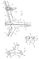
- Fig. 1 illustrates two mirror images of the same design gusset plates and Fig. 2 a foot part in oblique view.
- Fig. 3 illustrates the arrangement of a gusset plate with a support and two support profiles, also in oblique view.
- the 4 and 5 show optional accessories in oblique view.
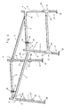
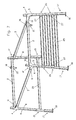
- the Fig. 6 and 7 illustrate a loading area construction using the gusset plates according to the invention and the accessories, again in an oblique view.
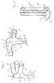
- Each gusset plate 4, 4 ' has two side parts 5, 6 facing each other at an angle 7, the angle 7, which these side parts 5, 6 enclose with one another, on the support profile 1, on which the gusset plate 4, 4' is to be mounted. is adapted, so that the two side parts 5, 6 abut well on the side surfaces of the support section 1.
- the side part 6 still has a support tab 8, which is provided such that the support profile 1 is not only U-shaped by the two side parts 5, 6, but also by the support tab 8 is included. Holes 9 provided in the side parts 5, 6 and in the support lug 8 make it possible to attach the support profile 1 to the gusset plate 4, 4 'by means of screw connections.
- each of the side flaps 10, 11 with a support tab 12, 13 for laying a support profile 2 or 3 is provided.
- the side flap 11 is provided with a cover flap 14, which is opposite to the support tab 12, so that the support profile 3 to be stored here is U-shaped of the support tab 12, the side flap 11 and the cover flap 14.
- Holes 9 in turn serve to connect this support section 3 in a simple manner by means of a screw connection with the gusset plate 4, 4 '.
- the second side flap 10 which is provided at the upper end of the gusset plate 4, 4 ', has a height which is not greater than the height of the bearing on the support tab 13 reaching support profile 2, so that the gusset plate 4 or 4'hhenfact this support profile 2 is not surmounted.
- holes 9 are provided, which serve to connect this support section 2 with the gusset plate 4 and 4 'by means of a screw connection in a simple manner.
- the transition of the side flaps 10, 11 to the side parts 5, 6 of the gusset plates 4, 4 ' is preferably rounded, whereby each gusset plate 4, 4' in addition to a good appearance also has an increased load capacity.
- the gusset plates 4, 4 ' are preferably integrally bent from a sheet, so that in the production of a gusset plate 4, 4' only punching and bending work - in addition to providing the holes - incurred, and no welding is necessary.
- the gusset plates 4, 4 ' are formed from as stable a sheet as possible, e.g. an aluminum alloy or a steel sheet, which may be coated, if it is not stainless.
- the gusset plates 4, 4 ' are designed mirror images of the same, that an approximately rectangular frame can be formed by the support sections 2, 3.
- the support profiles 1 project beyond the gusset plates 4, 4 ', and two support profiles 2 extending in the transverse direction to the loading area of a freight vehicle are provided in height above the carrying profiles 3 extending in the longitudinal direction of the loading area of the load vehicle, which results in the arrangement of the side straps 10 , 11 of the gusset plates 4, 4 'is taken into account.
- a transport device for long goods snap fasteners 15 may be provided, which are attached either to a support section 2 or to a gusset plate 4 ', wherein the headband 16 of Snap fasteners 15 project beyond the upper edge of the transversely extending support profiles 2.
- the longitudinally extending support profiles 3 can of course also be used to support loads, but they are used primarily for stiffening or for supporting the transversely extending support profiles 2 and the support profiles.
- 1 Fig. 6 indicates that the support profiles 1 do not extend exactly vertically, but are provided slightly inclined to each other, which is also taken into account in the design of the gussets 4, 4 '.
- Fig. 2 For attaching the loading area structure to a loading area serve in Fig. 2 shown foot parts 17, which are formed by a bottom plate 18 and thereof towering side members 19. Both the bottom plate 18 and the side parts 19 in turn have holes 9 for mechanical fastening to the loading area or to the support profiles 1 by means of screw connections.
- the upwardly extending side parts 19 of the foot part 17 suitably comprise a support profile 1 U-shaped, so that a particularly good hold of the support profile 1 is given.
- a bore 9 is also provided below the to be provided support profile 1, which, when the loading space structure is mounted on the truck is covered by the support profile 1, so that it is not readily possible, the loading area of the loading surface by releasing the visible Remove screw connections. Namely, it would have to be previously additionally removed the support sections 1 of the foot parts 17, which is a considerable expense.
- a further support profile 20 is provided, which is expediently fastened at a height to the support profiles 1, in which the upper edge of a rear side wall of a load vehicle is surmounted by this support profile 20 and on this support section 20 also long goods can be launched without the opening and closing of the side wall is obstructed.
- the measures provided for the support section 20 fasteners are in Fig. 4 shown; it is further gusset plates 21 with a U-profile forming side parts 22, 23 with only one of a side part 23 projecting side flap 24, to which also by means of screw the support profile can be attached.
- the side parts 22, 23 comprise the support profile 1U-shaped and are attached to this also by means of screw connections.
- This gusset plate can also be attached to the Side tab 24 have a support tab similar to the support tab 13 for the support section 20.
- a support profile 1 U-shaped embracing fasteners 26 are provided, the attachment to the support profiles 1 also by means of a screw can be realized.
- These fasteners 26 are further provided with adapted to the profile of the rear window protection 25 mounting tabs 27, where the rear window guard 25, as in Fig. 7 illustrated, can be mounted in a simple manner.
- the invention enables the simple assembly of a bed structure, which is adaptable to the loading area in width, length and height. It only need the support sections 1 and the support sections 2, 3 are cut to length according to the desired length, the gussets 4, 4 'can then be connected as desired with the profiles 1, 2, 3.
- the already existing holes 9 and the support tabs 12, 13 allow a very quick and easy installation of the loading area structure, with no welding is necessary, so also eliminates welding pre-and post-work.
- a loading area structure can be sent in a simple manner and space-saving in not yet assembled state, often only the knots 4, 4 'and the foot parts 17 and optionally accessories 21, 26 must be sent for the assembly of another support section 20 or a rear window protection 25, Especially since many companies that need a loading area structure, even have corresponding profiles 1, 2, 3.
Landscapes
- Engineering & Computer Science (AREA)
- Chemical & Material Sciences (AREA)
- Combustion & Propulsion (AREA)
- Transportation (AREA)
- Mechanical Engineering (AREA)
- Body Structure For Vehicles (AREA)
- Auxiliary Methods And Devices For Loading And Unloading (AREA)
- Vehicle Step Arrangements And Article Storage (AREA)
Claims (14)
- Plaque gousset (4, 4') pour relier trois profilés disposés en angle les uns par rapport aux autres (1, 2, 3) d'une superstructure de surface de chargement pour camions, dans laquelle la plaque gousset (4, 4') comprend un profilé en équerre formé par deux parties latérales (5, 6) avec une arête d'équerre (K) formée par les parties latérales (5, 6), pour la fixation, de préférence pour la fixation mécanique, sur un profilé de soutien (1) qui transmet les forces verticales de la superstructure de surface de chargement vers la surface de chargement, et dans laquelle la plaque gousset comprend, dans le prolongement des deux parties latérales (5, 6), des pattes latérales (10, 11) pour la fixation, de préférence pour la fixation mécanique, de profilés porteurs (2, 3) s'étendant approximativement horizontalement, caractérisée en ce que la plaque gousset (4, 4') est conçue d'une seule pièce à partir d'une pièce conformée en tôle, dans laquelle chacune des pattes latérales (10, 11) est pourvue d'une patte d'appui (12, 13) pour l'appui des profilés porteurs (2, 3) s'étendant approximativement horizontalement.
- Plaque gousset (4, 4') selon la revendication 1, caractérisée en ce qu'au moins une patte latérale (11) comprend une patte de couverture (14), disposée parallèlement à la patte d'appui (12) pour enserrer en forme de U un profilé porteur (3).
- Plaque gousset (4, 4') selon la revendication 1 ou 2, caractérisée en ce qu'une partie latérale (6) est pourvue d'une patte de soutien (8) orientée parallèlement à l'autre partie latérale (5) pour enserrer en forme de U un profilé de soutien (1).
- Plaque gousset (4, 4') selon l'une des revendications 1 à 3, caractérisée en ce que les pattes latérales (10, 11) se transforment par un arrondi vers les parties latérales (5, 6).
- Plaque gousset (4, 4') selon l'une des revendications 1 à 4, caractérisée en ce que les pattes latérales (10, 11) sont agencées sur les parties latérales (5, 6) dans des plans inégaux, c'est-à-dire décalées en hauteur.
- Plaque gousset (4, 4') selon l'une des revendications 1 à 5, caractérisée en ce que des perçages (9) sont prévus dans les parties latérales (5, 6) et dans les pattes latérales (10, 11) pour la fixation mécanique de profilés de soutien et/ou de profilés porteurs.
- Plaque gousset (4, 4') selon l'une des revendications 1 à 6, caractérisée par une fermeture rapide (15), fixée sur la face extérieure d'une patte latérale (10), dont l'arceau de maintien (16) dépasse au-delà de l'arête supérieure de la patte latérale (10).
- Kit pour la réalisation autonome d'une superstructure de surface de chargement en utilisant quatre plaques goussets (4, 4') de conception identique et symétrique selon l'une des revendications 1 à 7 dans le but de la réalisation d'une superstructure de surface de chargement formée de quatre profilés de soutien (1) et de quatre profilés supports (2, 3).
- Kit selon la revendication 8, caractérisé en ce qu'il est prévu en outre des pièces de pied (17) pour les profilés de soutien (1) qui comprennent chacune une plaque de fond (18) fixée à la surface de chargement, de préférence fixée par voie mécanique, et des parties latérales (19) dépassant de ces dernières, présentant de préférence une section transversale en U, pour la fixation, de préférence pour la fixation mécanique, des profilés de soutien (1).
- Kit selon la revendication 8 ou 9, caractérisé en ce qu'il comprend d'autres plaques goussets (21) avec des parties latérales (22, 23) formant de préférence un profil en U, et seulement une patte latérale (24) en porte-à-faux depuis une partie latérale et depuis laquelle dépasse de préférence une patte d'appui, également en porte-à-faux.
- Kit selon l'une des revendications 8 à 10, caractérisé par deux ou plusieurs pièces de fixation (26) qui enserrent un profilé de soutien (1), de préférence en forme de U, pour le montage d'une protection pour vitre arrière (25).
- Superstructure de surface de chargement, réalisée avec un kit selon l'une des revendications 8 à 11, caractérisée par quatre profilés de soutien (1) qui dépassent vers le haut au-delà des plaques goussets (4, 4').
- Superstructure de surface de chargement selon la revendication 12, caractérisée en ce que les plaques goussets (4, 4') se terminent en hauteur avec des profilés porteurs (2) s'étendant en direction transversale par rapport au camion, c'est-à-dire sans dépasser ceux-ci en hauteur.
- Superstructure de surface de chargement selon la revendication 12 ou 13, caractérisée en ce qu'il est prévu des profilés porteurs (3), s'étendant en direction longitudinale du camion, situés plus profondément que des profilés porteurs (2) s'étendant transversalement à la direction longitudinale du camion.
Applications Claiming Priority (1)
| Application Number | Priority Date | Filing Date | Title |
|---|---|---|---|
| AT0166506A AT503797B1 (de) | 2006-10-04 | 2006-10-04 | Knotenblech zum verbinden von drei im winkel zueinander stehenden profilen eines ladeflächenaufbaus für lastfahrzeuge |
Publications (3)
| Publication Number | Publication Date |
|---|---|
| EP1908670A2 EP1908670A2 (fr) | 2008-04-09 |
| EP1908670A3 EP1908670A3 (fr) | 2008-12-31 |
| EP1908670B1 true EP1908670B1 (fr) | 2012-02-15 |
Family
ID=38656475
Family Applications (1)
| Application Number | Title | Priority Date | Filing Date |
|---|---|---|---|
| EP07450173A Active EP1908670B1 (fr) | 2006-10-04 | 2007-10-04 | Plaque de renforcement destinée à relier trois profils se trouvant l'un contre l'autre dans l'angle d'une construction de surface de chargement pour camions |
Country Status (2)
| Country | Link |
|---|---|
| EP (1) | EP1908670B1 (fr) |
| AT (2) | AT503797B1 (fr) |
Cited By (1)
| Publication number | Priority date | Publication date | Assignee | Title |
|---|---|---|---|---|
| WO2025207070A1 (fr) * | 2024-03-28 | 2025-10-02 | Tirsan Treyler Sanayi̇ Ve Ti̇caret Anoni̇m Şi̇rketi̇ | Support de montage d'angle avant de corps monolithique doté d'un élément de montage de feu de position avant pour véhicules à remorque |
Families Citing this family (3)
| Publication number | Priority date | Publication date | Assignee | Title |
|---|---|---|---|---|
| DE102013002659A1 (de) * | 2013-02-15 | 2014-08-21 | Man Truck & Bus Ag | Rahmenstruktur für den Aufbau eines Nutzfahrzeugs |
| CN106143650B (zh) * | 2016-07-29 | 2018-09-04 | 北京汽车研究总院有限公司 | 一种汽车的角连接板结构及汽车 |
| US11130524B2 (en) * | 2019-10-25 | 2021-09-28 | Caterpillar Inc. | Space frame center upper frame connection |
Family Cites Families (6)
| Publication number | Priority date | Publication date | Assignee | Title |
|---|---|---|---|---|
| US1629278A (en) * | 1925-04-27 | 1927-05-17 | Heintz Mfg Co | Post connection for vehicle bodies |
| US2080764A (en) * | 1936-11-05 | 1937-05-18 | Wilbur F Crawford | Vehicle bow support |
| DE2728450C2 (de) * | 1977-06-24 | 1986-04-30 | Wackenhut, Ernst, 7270 Nagold | Plangestell, insbesondere für Lkw |
| AU517487B2 (en) * | 1979-01-23 | 1981-08-06 | Whitlock, C.F. | Freight handling system |
| US5071185A (en) * | 1990-01-29 | 1991-12-10 | Schiele Jim D | Truck bed enclosure |
| AU7458098A (en) * | 1998-06-01 | 1999-12-20 | Abb Daimler-Benz Transportation, S.A. | Connecting element for structures for railway passenger vehicles |
-
2006
- 2006-10-04 AT AT0166506A patent/AT503797B1/de active
-
2007
- 2007-10-04 AT AT07450173T patent/ATE545570T1/de active
- 2007-10-04 EP EP07450173A patent/EP1908670B1/fr active Active
Cited By (1)
| Publication number | Priority date | Publication date | Assignee | Title |
|---|---|---|---|---|
| WO2025207070A1 (fr) * | 2024-03-28 | 2025-10-02 | Tirsan Treyler Sanayi̇ Ve Ti̇caret Anoni̇m Şi̇rketi̇ | Support de montage d'angle avant de corps monolithique doté d'un élément de montage de feu de position avant pour véhicules à remorque |
Also Published As
| Publication number | Publication date |
|---|---|
| ATE545570T1 (de) | 2012-03-15 |
| EP1908670A3 (fr) | 2008-12-31 |
| AT503797B1 (de) | 2008-01-15 |
| EP1908670A2 (fr) | 2008-04-09 |
| AT503797A4 (de) | 2008-01-15 |
Similar Documents
| Publication | Publication Date | Title |
|---|---|---|
| DE2945550A1 (de) | Lastentraggestell | |
| DE29800368U1 (de) | Geschraubter Hilfsrahmen | |
| EP1908670B1 (fr) | Plaque de renforcement destinée à relier trois profils se trouvant l'un contre l'autre dans l'angle d'une construction de surface de chargement pour camions | |
| EP3882109B1 (fr) | Profilé de châssis extérieur pour un châssis extérieur pour un véhicule utilitaire | |
| EP3037325B1 (fr) | Cadre de montage contrevente et facile a monter pour un vehicule de transport de charges | |
| DE102019116048A1 (de) | Regalsystem und Ladungssicherungseinrichtung | |
| EP2420406B1 (fr) | Dispositif de sécurisation d'un chargement sur la surface de chargement d'un montage de véhicule | |
| EP3428086A1 (fr) | Système de stockage et/ou de transport pour éléments de clôture transportables | |
| EP2682303B1 (fr) | Profil extrudé et véhicule | |
| EP1826101A2 (fr) | Création pour un camping-car | |
| EP0590278B1 (fr) | Vitrine | |
| DE10013239A1 (de) | Trailer-Anhänger | |
| EP3348455B1 (fr) | Structure de support pour un véhicule utilitaire non entraîné | |
| DE19706493A1 (de) | LKW-Aufbau | |
| DE2728963C3 (de) | Runge für Lastkraftwagen und Anhänger | |
| DE20009676U1 (de) | Runge für Nutzfahrzeuge | |
| DE10036791B4 (de) | Kraftwagen mit einer Tragstruktur aus Zusammengesetzten Leichtbauplatten | |
| DE20220363U1 (de) | Flurförderzeug mit einer Fahrerkabine und einer Klemmvorrichtung für Anbauteile | |
| EP2083127B1 (fr) | Tête de liaison et système destiné à l'établissement de structures | |
| DE3812506A1 (de) | Plangestell, insbesondere fuer lastkraftwagen und anhaenger | |
| DE202021004415U1 (de) | Heckträger | |
| EP1092613A2 (fr) | Brancard extérieur pour véhicule | |
| DE102005039355B4 (de) | Vorrichtung und Verfahren zum Befestigen von Wechselbehältern an Trägerfahrzeugen | |
| DE102023101517B4 (de) | Zweiteilige Schutzdachzelle für ein Fahrzeug | |
| EP1028024A2 (fr) | Dispositif pour attacher au moins un point de fixation sur un profile pour un système d'arrimage et véhicule avec profile |
Legal Events
| Date | Code | Title | Description |
|---|---|---|---|
| PUAI | Public reference made under article 153(3) epc to a published international application that has entered the european phase |
Free format text: ORIGINAL CODE: 0009012 |
|
| AK | Designated contracting states |
Kind code of ref document: A2 Designated state(s): AT BE BG CH CY CZ DE DK EE ES FI FR GB GR HU IE IS IT LI LT LU LV MC MT NL PL PT RO SE SI SK TR |
|
| AX | Request for extension of the european patent |
Extension state: AL BA HR MK RS |
|
| PUAL | Search report despatched |
Free format text: ORIGINAL CODE: 0009013 |
|
| AK | Designated contracting states |
Kind code of ref document: A3 Designated state(s): AT BE BG CH CY CZ DE DK EE ES FI FR GB GR HU IE IS IT LI LT LU LV MC MT NL PL PT RO SE SI SK TR |
|
| AX | Request for extension of the european patent |
Extension state: AL BA HR MK RS |
|
| 17P | Request for examination filed |
Effective date: 20090227 |
|
| 17Q | First examination report despatched |
Effective date: 20090408 |
|
| AKX | Designation fees paid |
Designated state(s): AT BE BG CH CY CZ DE DK EE ES FI FR GB GR HU IE IS IT LI LT LU LV MC MT NL PL PT RO SE SI SK TR |
|
| GRAP | Despatch of communication of intention to grant a patent |
Free format text: ORIGINAL CODE: EPIDOSNIGR1 |
|
| GRAS | Grant fee paid |
Free format text: ORIGINAL CODE: EPIDOSNIGR3 |
|
| GRAA | (expected) grant |
Free format text: ORIGINAL CODE: 0009210 |
|
| AK | Designated contracting states |
Kind code of ref document: B1 Designated state(s): AT BE BG CH CY CZ DE DK EE ES FI FR GB GR HU IE IS IT LI LT LU LV MC MT NL PL PT RO SE SI SK TR |
|
| REG | Reference to a national code |
Ref country code: CH Ref legal event code: EP Ref country code: GB Ref legal event code: FG4D Free format text: NOT ENGLISH |
|
| REG | Reference to a national code |
Ref country code: IE Ref legal event code: FG4D Free format text: LANGUAGE OF EP DOCUMENT: GERMAN |
|
| REG | Reference to a national code |
Ref country code: AT Ref legal event code: REF Ref document number: 545570 Country of ref document: AT Kind code of ref document: T Effective date: 20120315 |
|
| REG | Reference to a national code |
Ref country code: CH Ref legal event code: NV Representative=s name: BRAUNPAT BRAUN EDER AG |
|
| REG | Reference to a national code |
Ref country code: DE Ref legal event code: R096 Ref document number: 502007009277 Country of ref document: DE Effective date: 20120412 |
|
| REG | Reference to a national code |
Ref country code: NL Ref legal event code: VDEP Effective date: 20120215 |
|
| LTIE | Lt: invalidation of european patent or patent extension |
Effective date: 20120215 |
|
| PG25 | Lapsed in a contracting state [announced via postgrant information from national office to epo] |
Ref country code: NL Free format text: LAPSE BECAUSE OF FAILURE TO SUBMIT A TRANSLATION OF THE DESCRIPTION OR TO PAY THE FEE WITHIN THE PRESCRIBED TIME-LIMIT Effective date: 20120215 Ref country code: IS Free format text: LAPSE BECAUSE OF FAILURE TO SUBMIT A TRANSLATION OF THE DESCRIPTION OR TO PAY THE FEE WITHIN THE PRESCRIBED TIME-LIMIT Effective date: 20120615 Ref country code: LT Free format text: LAPSE BECAUSE OF FAILURE TO SUBMIT A TRANSLATION OF THE DESCRIPTION OR TO PAY THE FEE WITHIN THE PRESCRIBED TIME-LIMIT Effective date: 20120215 |
|
| PG25 | Lapsed in a contracting state [announced via postgrant information from national office to epo] |
Ref country code: FI Free format text: LAPSE BECAUSE OF FAILURE TO SUBMIT A TRANSLATION OF THE DESCRIPTION OR TO PAY THE FEE WITHIN THE PRESCRIBED TIME-LIMIT Effective date: 20120215 Ref country code: LV Free format text: LAPSE BECAUSE OF FAILURE TO SUBMIT A TRANSLATION OF THE DESCRIPTION OR TO PAY THE FEE WITHIN THE PRESCRIBED TIME-LIMIT Effective date: 20120215 Ref country code: PL Free format text: LAPSE BECAUSE OF FAILURE TO SUBMIT A TRANSLATION OF THE DESCRIPTION OR TO PAY THE FEE WITHIN THE PRESCRIBED TIME-LIMIT Effective date: 20120215 Ref country code: GR Free format text: LAPSE BECAUSE OF FAILURE TO SUBMIT A TRANSLATION OF THE DESCRIPTION OR TO PAY THE FEE WITHIN THE PRESCRIBED TIME-LIMIT Effective date: 20120516 Ref country code: PT Free format text: LAPSE BECAUSE OF FAILURE TO SUBMIT A TRANSLATION OF THE DESCRIPTION OR TO PAY THE FEE WITHIN THE PRESCRIBED TIME-LIMIT Effective date: 20120615 |
|
| REG | Reference to a national code |
Ref country code: IE Ref legal event code: FD4D |
|
| PG25 | Lapsed in a contracting state [announced via postgrant information from national office to epo] |
Ref country code: CY Free format text: LAPSE BECAUSE OF FAILURE TO SUBMIT A TRANSLATION OF THE DESCRIPTION OR TO PAY THE FEE WITHIN THE PRESCRIBED TIME-LIMIT Effective date: 20120215 |
|
| PG25 | Lapsed in a contracting state [announced via postgrant information from national office to epo] |
Ref country code: CZ Free format text: LAPSE BECAUSE OF FAILURE TO SUBMIT A TRANSLATION OF THE DESCRIPTION OR TO PAY THE FEE WITHIN THE PRESCRIBED TIME-LIMIT Effective date: 20120215 Ref country code: RO Free format text: LAPSE BECAUSE OF FAILURE TO SUBMIT A TRANSLATION OF THE DESCRIPTION OR TO PAY THE FEE WITHIN THE PRESCRIBED TIME-LIMIT Effective date: 20120215 Ref country code: SI Free format text: LAPSE BECAUSE OF FAILURE TO SUBMIT A TRANSLATION OF THE DESCRIPTION OR TO PAY THE FEE WITHIN THE PRESCRIBED TIME-LIMIT Effective date: 20120215 Ref country code: DK Free format text: LAPSE BECAUSE OF FAILURE TO SUBMIT A TRANSLATION OF THE DESCRIPTION OR TO PAY THE FEE WITHIN THE PRESCRIBED TIME-LIMIT Effective date: 20120215 Ref country code: SE Free format text: LAPSE BECAUSE OF FAILURE TO SUBMIT A TRANSLATION OF THE DESCRIPTION OR TO PAY THE FEE WITHIN THE PRESCRIBED TIME-LIMIT Effective date: 20120215 Ref country code: EE Free format text: LAPSE BECAUSE OF FAILURE TO SUBMIT A TRANSLATION OF THE DESCRIPTION OR TO PAY THE FEE WITHIN THE PRESCRIBED TIME-LIMIT Effective date: 20120215 Ref country code: IE Free format text: LAPSE BECAUSE OF FAILURE TO SUBMIT A TRANSLATION OF THE DESCRIPTION OR TO PAY THE FEE WITHIN THE PRESCRIBED TIME-LIMIT Effective date: 20120215 |
|
| PG25 | Lapsed in a contracting state [announced via postgrant information from national office to epo] |
Ref country code: IT Free format text: LAPSE BECAUSE OF FAILURE TO SUBMIT A TRANSLATION OF THE DESCRIPTION OR TO PAY THE FEE WITHIN THE PRESCRIBED TIME-LIMIT Effective date: 20120215 Ref country code: SK Free format text: LAPSE BECAUSE OF FAILURE TO SUBMIT A TRANSLATION OF THE DESCRIPTION OR TO PAY THE FEE WITHIN THE PRESCRIBED TIME-LIMIT Effective date: 20120215 |
|
| PLBE | No opposition filed within time limit |
Free format text: ORIGINAL CODE: 0009261 |
|
| STAA | Information on the status of an ep patent application or granted ep patent |
Free format text: STATUS: NO OPPOSITION FILED WITHIN TIME LIMIT |
|
| 26N | No opposition filed |
Effective date: 20121116 |
|
| REG | Reference to a national code |
Ref country code: DE Ref legal event code: R097 Ref document number: 502007009277 Country of ref document: DE Effective date: 20121116 |
|
| BERE | Be: lapsed |
Owner name: LLE VERTRIEBS GMBH Effective date: 20121031 |
|
| PG25 | Lapsed in a contracting state [announced via postgrant information from national office to epo] |
Ref country code: MC Free format text: LAPSE BECAUSE OF NON-PAYMENT OF DUE FEES Effective date: 20121031 |
|
| GBPC | Gb: european patent ceased through non-payment of renewal fee |
Effective date: 20121004 |
|
| REG | Reference to a national code |
Ref country code: FR Ref legal event code: ST Effective date: 20130628 |
|
| PG25 | Lapsed in a contracting state [announced via postgrant information from national office to epo] |
Ref country code: GB Free format text: LAPSE BECAUSE OF NON-PAYMENT OF DUE FEES Effective date: 20121004 Ref country code: BG Free format text: LAPSE BECAUSE OF FAILURE TO SUBMIT A TRANSLATION OF THE DESCRIPTION OR TO PAY THE FEE WITHIN THE PRESCRIBED TIME-LIMIT Effective date: 20120515 Ref country code: BE Free format text: LAPSE BECAUSE OF NON-PAYMENT OF DUE FEES Effective date: 20121031 |
|
| PG25 | Lapsed in a contracting state [announced via postgrant information from national office to epo] |
Ref country code: FR Free format text: LAPSE BECAUSE OF NON-PAYMENT OF DUE FEES Effective date: 20121031 |
|
| PG25 | Lapsed in a contracting state [announced via postgrant information from national office to epo] |
Ref country code: ES Free format text: LAPSE BECAUSE OF FAILURE TO SUBMIT A TRANSLATION OF THE DESCRIPTION OR TO PAY THE FEE WITHIN THE PRESCRIBED TIME-LIMIT Effective date: 20120526 |
|
| PG25 | Lapsed in a contracting state [announced via postgrant information from national office to epo] |
Ref country code: MT Free format text: LAPSE BECAUSE OF FAILURE TO SUBMIT A TRANSLATION OF THE DESCRIPTION OR TO PAY THE FEE WITHIN THE PRESCRIBED TIME-LIMIT Effective date: 20120215 |
|
| REG | Reference to a national code |
Ref country code: AT Ref legal event code: MM01 Ref document number: 545570 Country of ref document: AT Kind code of ref document: T Effective date: 20121031 |
|
| PG25 | Lapsed in a contracting state [announced via postgrant information from national office to epo] |
Ref country code: AT Free format text: LAPSE BECAUSE OF NON-PAYMENT OF DUE FEES Effective date: 20121031 |
|
| PG25 | Lapsed in a contracting state [announced via postgrant information from national office to epo] |
Ref country code: TR Free format text: LAPSE BECAUSE OF FAILURE TO SUBMIT A TRANSLATION OF THE DESCRIPTION OR TO PAY THE FEE WITHIN THE PRESCRIBED TIME-LIMIT Effective date: 20120215 |
|
| PG25 | Lapsed in a contracting state [announced via postgrant information from national office to epo] |
Ref country code: LU Free format text: LAPSE BECAUSE OF NON-PAYMENT OF DUE FEES Effective date: 20121004 |
|
| PG25 | Lapsed in a contracting state [announced via postgrant information from national office to epo] |
Ref country code: HU Free format text: LAPSE BECAUSE OF FAILURE TO SUBMIT A TRANSLATION OF THE DESCRIPTION OR TO PAY THE FEE WITHIN THE PRESCRIBED TIME-LIMIT Effective date: 20071004 |
|
| PGFP | Annual fee paid to national office [announced via postgrant information from national office to epo] |
Ref country code: CH Payment date: 20151021 Year of fee payment: 9 |
|
| REG | Reference to a national code |
Ref country code: CH Ref legal event code: PL |
|
| PG25 | Lapsed in a contracting state [announced via postgrant information from national office to epo] |
Ref country code: LI Free format text: LAPSE BECAUSE OF NON-PAYMENT OF DUE FEES Effective date: 20161031 Ref country code: CH Free format text: LAPSE BECAUSE OF NON-PAYMENT OF DUE FEES Effective date: 20161031 |
|
| PGFP | Annual fee paid to national office [announced via postgrant information from national office to epo] |
Ref country code: DE Payment date: 20251020 Year of fee payment: 19 |