EP1908425B1 - Medizinisches Rohrschaftinstrument - Google Patents
Medizinisches Rohrschaftinstrument Download PDFInfo
- Publication number
- EP1908425B1 EP1908425B1 EP07015245A EP07015245A EP1908425B1 EP 1908425 B1 EP1908425 B1 EP 1908425B1 EP 07015245 A EP07015245 A EP 07015245A EP 07015245 A EP07015245 A EP 07015245A EP 1908425 B1 EP1908425 B1 EP 1908425B1
- Authority
- EP
- European Patent Office
- Prior art keywords
- handle
- pull
- push rod
- instrument according
- collets
- Prior art date
- Legal status (The legal status is an assumption and is not a legal conclusion. Google has not performed a legal analysis and makes no representation as to the accuracy of the status listed.)
- Active
Links
Images
Classifications
-
- A—HUMAN NECESSITIES
- A61—MEDICAL OR VETERINARY SCIENCE; HYGIENE
- A61B—DIAGNOSIS; SURGERY; IDENTIFICATION
- A61B17/00—Surgical instruments, devices or methods
- A61B17/28—Surgical forceps
- A61B17/29—Forceps for use in minimally invasive surgery
-
- A—HUMAN NECESSITIES
- A61—MEDICAL OR VETERINARY SCIENCE; HYGIENE
- A61B—DIAGNOSIS; SURGERY; IDENTIFICATION
- A61B17/00—Surgical instruments, devices or methods
- A61B2017/0046—Surgical instruments, devices or methods with a releasable handle; with handle and operating part separable
-
- A—HUMAN NECESSITIES
- A61—MEDICAL OR VETERINARY SCIENCE; HYGIENE
- A61B—DIAGNOSIS; SURGERY; IDENTIFICATION
- A61B17/00—Surgical instruments, devices or methods
- A61B2017/00477—Coupling
-
- A—HUMAN NECESSITIES
- A61—MEDICAL OR VETERINARY SCIENCE; HYGIENE
- A61B—DIAGNOSIS; SURGERY; IDENTIFICATION
- A61B17/00—Surgical instruments, devices or methods
- A61B17/28—Surgical forceps
- A61B17/29—Forceps for use in minimally invasive surgery
- A61B17/2909—Handles
- A61B2017/2912—Handles transmission of forces to actuating rod or piston
- A61B2017/2919—Handles transmission of forces to actuating rod or piston details of linkages or pivot points
- A61B2017/292—Handles transmission of forces to actuating rod or piston details of linkages or pivot points connection of actuating rod to handle, e.g. ball end in recess
Definitions
- the invention relates to a medical tubular shaft instrument having a hollow shaft, arranged at the proximal end of the shaft, provided with at least two handle parts handle and at least one mounted in the hollow shaft pull / push rod, arranged at the distal end of a tool consisting of at least two jaw parts is, wherein the pull / push rod for opening and closing at least one jaw part of the tool with at least one pivotable handle portion of the handle is coupled and wherein the pull / push rod and the handle via a coupling mechanism are releasably connected to each other, having as at least one clamping jaw Clamping device is formed.
- Such medical tubular shaft instruments find use, for example, in the training as a needle holder in endoscopic surgery. Due to increasing hygienic requirements is increasingly required that in particular cavities, such as hollow shafts; having tubular shaft instruments are formed at least partially dismantled, in order to undergo a thorough cleaning and sterilization, preferably steam sterilization.
- the object of the invention is to develop a medical tubular shaft instrument such that the pull / push rod and the handle can be detachably connected to one another via a coupling mechanism that is essentially free from play and easy to manufacture.
- a control pin engaging in the guideway is arranged on each clamping jaw mounted in a guideway.
- the clamping device has two clamping jaws.
- the clamping jaws of the clamping device, the proximal end of the pull / push rod engage around at least partially form-fitting manner, wherein the proximal end of the pull / push rod is preferably formed as a coupling element at least partially encompassed by the clamping jaws.
- the formation of the proximal end of the pull / push rod gripping jaws allows a space-saving design of the coupling mechanism with good power transmission due to the large transfer surface.
- the coupling element according to the invention is designed as an extension of the pull / push rod which is located downstream in the axial direction of the clamping point formed by the clamping jaws.
- the pull / push rod in the form of locking or frictionally locking in the field, but in each case clamped by means of the jaws set.
- the coupling element is formed by a constriction of the pull / push rod upstream of the proximal end in the axial direction.
- At least one of the clamping jaws is designed as a spring element, wherein the elasticity of this at least one clamping jaw not only by the inherent elasticity of the clamping jaw material, but also the spring load of at least one clamping jaw is achieved.
- the insertion of the proximal end of the push / push rod into the clamping device can be facilitated according to the invention in that the connecting element and / or the clamping jaws are provided with tilting of the run-on bevels preventing against each other.
- clamping jaws are pivotally mounted on a coupleable with the at least one pivotable handle portion of the handle connecting member.
- the clamping device is biased by a spring element in the clamping jaw opening position to allow easy release of the clutch.
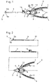
- Fig. 1 and 2 illustrated designed as a needle holder medical Rohrschaftinstrument consists essentially of a provided with two handle parts 1 handle 2, a hollow shaft 3 and an insertable into the hollow shaft 3 pull / push rod 4, at the distal end of a two jaw parts 5a and 5b existing Tool 5 is arranged.
- FIG. 2 particularly clearly illustrated assemblies handle 2, hollow shaft 3 and pull / push rod 4 are coupled to each other via coupling and locking mechanisms that by pressing the handle parts 1 of the handle 2, the jaws 5a and 5b of the tool 5 between an open and a closed Working position are adjustable, wherein the user applied to the handle parts 1 of the handle 2 forces on the pull / push rod 4 on the jaws 5a, 5b of the tool 5 are transmitted.
- the tool 5 has a rigid jaw part 5a and a jaw part 5b which can be pivoted relative to the rigid jaw part 5a.
- both jaw parts of the tool 5 as pivotable jaw parts 5b.
- both handle parts 1 of the handle 2 are formed as pivotable handle parts 1 in the illustrated embodiment, which are pivotally mounted on pivot points 6 on a housing 7 of the handle 2.
- both handle parts 1 are connected via a respective articulated lever 8 with a coupling rod 9 , which in turn is coupled directly or indirectly via a coupling mechanism with the push / pull rod 4, wherein the coupling of the pull / push rod 4 takes place with the coupling rod 9 and thus with the handle 2 in the clutch housing 10.
- the coupling of the pull / push rod 4 and thus also the jaws 5a and 5b of the tool 5 with the handle parts 1 of the handle 2 is designed so that when squeezing the handle parts 1, the pull / push rod 4 via the articulated lever 8 and the coupling rod. 9 is pulled in the axial direction to the proximal end of the instrument.
- This axial displacement of the pull / push rod 4 to the proximal end of the instrument causes a transfer of the jaws 5a, 5b of the tool 5 in the closed working position.
- the handle parts 1 via a locking device 11 are fixed against each other, so that the user does not have to exert the pressure force on the handle parts 1 of the handle 2 the entire time.
- an unlock button 12 which separates the parts of the locking device 11, this fixation is canceled.
- the coupling of the pull / push rod 4 and thus also of the jaw parts 5a and 5b of the tool 5 with the handle parts 1 of the handle 2 is designed so that the pull / push rod 4 is pushed when squeezing the handle parts 1 in the axial direction to the distal end of the instrument.
- the handle parts 1 are biased by a spring element 13 in the open position, which, such as in Fig. 3 shown, is arranged in the clutch housing 10.
- this spring element 13 pushes the push / pull rod 4 in the axial direction to the distal end of the instrument, whereby the handle parts 1 are pressed apart via the coupling rod 9 and the hinge lever 8.
- This axial displacement of the pull / push rod 4 to the distal end of the instrument causes a transfer of the jaws 5a, 5b of the tool 5 in the open working position.
- the handle 2 with two pivotable handle parts 1 it is of course also possible only one handle part 1 pivotally form, whereas the other handle part is then for example integrally formed rigidly with the housing 7 of the handle 2. In such a configuration, it is possible to couple the pull / push rod 4 directly to the pivotable handle part 1.
- the hollow shaft 3 serving to receive the pull / push rod 4 can be coupled to the handle 2 via a coupling or latching mechanism which is arranged in the housing 7 of the handle 2.
- the hollow shaft 3 furthermore has a flushing connection 14, which on the one hand serves to introduce flushing fluid during an operation and to which on the other hand a flushing hose can be connected for cleaning the hollow shaft 3.
- the hollow shaft 3 has a coupling or locking mechanism in order to be able to couple the hollow shaft 3 and the pull / push rod 4 which can be inserted into it.
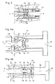
- the structure of the clutch mechanism 10 arranged in the coupling mechanism for releasably connecting the pull / push rod 4 with the handle 2 is the figures Fig. 3 to 4b refer to.
- This coupling mechanism is designed as a clamping device 15, which consists in the illustrated embodiment of two pivotally mounted clamping jaws 16 which engage around the proximal end of the pull / push rod 4 at least partially positively.
- a coupling element 17 is formed at the proximal end of the pull / push rod 4, which is formed in the illustrated embodiment as a hammerhead-shaped by an axially upstream of the proximal end constriction 18.
- 16 run-on slopes 19 are formed at the mutually-facing end faces of both the coupling element 17 and the clamping jaws, by which the frictional resistance of the mutually-starting components is reduced.
- the two jaws 16 are pivotally mounted with their proximal ends on the distal side of a connecting member 20 which rests on a spring element 21 on the coupling rod 9, which in turn is coupled via the hinge lever 8 with the handle parts 1.
- spring element 21 When arranged in the coupling region of the pull / push rod 4 with the handle 2 spring element 21 is designed as an overload spring 21 overload protection that prevents excessive force into the pull / push rod 4. If already closed jaw parts 5a and 5b of the tool 5, the handle parts 1 of the handle 2 are further compressed, this is collected on the coupling rod 9 and the connecting member 20 on the pull / push rod 4 to be transmitted tensile force from the overload spring 21 and thus prevents a Damage to the pull / push rod 4 and / or the jaws 5a and 5b of the tool 5. Also prevents the overload protection during backup the clamping jaw 16 caused by the clamping connection a possible damage of the connecting member 20 and the clamping jaws 16th
- the clamping jaws 16 are each mounted on a control pin 22 in a guide track 23. About this pin-slot control, the jaws 16 at an axial displacement of the clamping device 15 between the open mounting position ( Fig. 4a ) and the closed clamping position ( Fig ,. 4b ) adjusted.
- the guideways 23 are angled radially outwards only at their distal ends, but otherwise run parallel to the instrument longitudinal axis 24, the clamping jaws 16 can only be opened when the control journals 22 guiding the clamping jaws 16 enter these distal-side angled portions of the guideways 23 and thus pivot the jaws 16 in the open mounting position.
- clamping jaws 16 As an alternative to the illustrated embodiment of the clamping jaws 16, it is of course also possible to design these as spring elements or resilient clamping jaws 16, which are biased by residual stress or an external spring force in the closed position and thus embrace the proximal end of the pull / push rod 4 form-fitting clamping.
- the pull / push rod 4 and the hollow shaft 3 are coupled together and the hollow shaft 3 is connected to the handle 2.
- the handle parts 1 of the handle 2 are pressed as far apart as possible in the open position, wherein they are supported by the arranged in the clutch housing 10 spring element 13.
- the pressing apart of the handle parts 1 of the handle 2 causes via the hinge lever 8 an axial displacement of the coupling rod 9 in the direction of the distal end of the tubular shaft instrument. Due to the direct coupling of the coupling rod 9 with the connecting member 20, on which the clamping jaws 16 are mounted, the pressing apart of the handle parts 1 of the handle 2 further causes a displacement of the clamping jaws 16 in the distal direction.
- the pin-slot control of engaging in the guideways 23 control pin 22 the clamping jaws 16 in this axial displacement in the in Fig. 4a transferred illustrated open mounting position.
- the pull / push rod 4 can now be introduced with the proximal end designed as a coupling element 17 in the open jaws 16, which is facilitated by the bevels formed on both sides 19.
- the handle parts 1 of the handle 2 take an over-open position, which they can never take in the practical handling of the instrument.
- This over-open position of the handle parts 1 is used solely for mounting the pull / push rod 4, whereby accidental release of the pull / push rod 4 can be excluded during normal operation.
- the pull / push rod 4 is further pressed in the axial direction towards the proximal end of the tubular shaft instrument, which can be supported by the compression of the handle parts 1 of the handle 2.
- the clamping jaws 16 are displaced proximally along the guideways 23, whereby they are transferred into the closed, the proximal end of the pull / push rod 4 form-fitting encompassing position.
- the clamping device 15 causes a play-free and reliable coupling of the pull / push rod 4 with the handle second
- the disassembly then takes place in exactly the reverse order of the assembly steps on the release of the locking between the hollow shaft 3 and the handle 2, the release of the connection of the pull / push rod 4 with the handle parts 1 of the handle 2 to decoupling the hollow shaft.
- the handle parts 1 are again as far as possible pressed apart until the jaws 16 again in Fig. 4a have taken shown mounting position and subsequently the pull / push rod 4 can be decoupled from the handle 2.
Landscapes
- Health & Medical Sciences (AREA)
- Surgery (AREA)
- Life Sciences & Earth Sciences (AREA)
- Medical Informatics (AREA)
- Animal Behavior & Ethology (AREA)
- Engineering & Computer Science (AREA)
- Biomedical Technology (AREA)
- Heart & Thoracic Surgery (AREA)
- Ophthalmology & Optometry (AREA)
- Molecular Biology (AREA)
- Nuclear Medicine, Radiotherapy & Molecular Imaging (AREA)
- General Health & Medical Sciences (AREA)
- Public Health (AREA)
- Veterinary Medicine (AREA)
- Surgical Instruments (AREA)
- Media Introduction/Drainage Providing Device (AREA)
- Materials For Medical Uses (AREA)
- Ultra Sonic Daignosis Equipment (AREA)
Description
- Die Erfindung betrifft ein medizinisches Rohrschaftinstrument mit einem hohlen Schaft, einer am proximalem Ende des Schaftes angeordneten, mit mindestens zwei Griffteilen versehenen Handhabe und mindestens einer in dem hohlen Schaft gelagerten Zug-/Schubstange, an deren distalem Ende ein aus mindestens zwei Maulteilen bestehendes Werkzeug angeordnet ist, wobei die Zug-/Schubstange zum Öffnen und Schließen mindestens eines Maulteils des Werkzeugs mit mindestens einem verschwenkbaren Griffteil der Handhabe koppelbar ist und wobei die Zug-/Schubstange und die Handhabe über einen Kopplungsmechanismus lösbar miteinander verbindbar sind, der als mindestens eine Spannbacke aufweisende Klemmvorrichtung ausgebildet ist.
- Derartige medizinische Rohrschaftinstrumente finden beispielsweise in der Ausbildung als Nadelhalter Verwendung in der endoskopischen Chirurgie. Aufgrund steigender hygienischer Anforderungen wird immer häufiger gefordert, dass insbesondere Hohlräume, wie beispielsweise hohle Schäfte; aufweisende Rohrschaftinstrumente zumindest teilweise zerlegbar ausgebildet sind, um diese einer gründlichen Reinigung und Sterilisation, vorzugsweise Dampfsterilisation, unterziehen zu können.
- Aus der
DE 43 07 539 A1 ist ein gattungsgemäßes, als medizinische Zange ausgebildetes medizinisches Rohrschaftinstrument bekannt. Dieses bekannte Rohrschaftinstrument lässt sich zum Reinigen und Sterilisieren in drei Hauptgruppen zerlegen, die Zug-/Schubstange, den hohlen Schaft sowie die Handhabe. Der Kopplungsmechanismus zum Verbinden der Zug-/Schubstange mit der Handhabe besteht bei dieser Konstruktion aus einer am proximalen Ende der Zug-/Schubstange angeordneten Kupplungskugel, die in eine korrespondierend geformte Kupplungsaufnahme im verschwenkbaren Griffteil einzusetzen ist. Zwar hat sich diese Kupplung in der Praxis bewährt, jedoch bedarf diese Kupplung einer sehr exakten Fertigung der Zug-/Schubstange.DE 10 2004 025 041 beschreibt ein Instrument gemäß Präambel des Anspruchs 1. - Davon ausgehend liegt der Erfindung die Aufgabe zugrunde, ein medizinisches Rohrschaftinstrument derart weiterzubilden, dass die Zug-/Schubstange und die Handhabe über einen im Wesentlichen spielfreien und einfach zu fertigenden Kopplungsmechanismus lösbar miteinander verbindbar sind.
- Die Lösung dieser Aufgabenstellung ist erfindungsgemäß in den kennzeichnenden Teil des Anspruchs 1 zu finden.
- Aufgrund dieser Ausgestaltung des Kopplungsmechanismus als eine mit mindestens eine in einer Führungsbahn gelagerte Spannbacke wird eine im Wesentlichen spielfreie Kopplung zwischen der Zug-/Schubstange und der Handhabe sichergestellt, die auch Längenabweichungen der Zug-/Schubstange toleriert.
- Durch die Lagerung der Spannbacke in der Führungsbahn wird das Verschwenken der mindestens einen Spannbacke zwischen der geschlossen Klemmposition und der offenen Montageposition erleichtert, wobei durch die Ausbildung der Führung für die Spannbackenverstellung eine exakte und gleichmäßige Überführung der mindestens einen Spannbacke in die jeweilige Kopplungsposition gewährleistet wird. Erfindungsgemäß ist an jeder in einer Führungsbahn gelagerten Spannbacke ein in die Führungsbahn eingreifender Steuerzapfen angeordnet.
- Gemäß einer bevorzugten Ausführungsform der Erfindung weist die Klemmvorrichtung zwei Spannbacken auf.
- Gemäß einer praktischen Ausführungsform der Erfindung wird vorgeschlagen, dass die Spannbacken der Klemmvorrichtung das proximale Ende der Zug-/Schubstange zumindest teilweise formschlüssig umgreifen, wobei das proximale Ende der Zug-/Schubstange vorzugsweise als von den Spannbacken zumindest teilweise umgreifbares Kopplungselement ausgebildet ist. Die Ausbildung der das proximale Ende der Zug-/Schubstange ergreifenden Spannbacken ermöglicht eine platzsparende Bauweise des Kopplungsmechanismus bei gleichzeitig guter Kraftübertragung aufgrund der großen Übertragungsfläche.
- Zur Ausbildung der Klemmverbindung zwischen den Spannbacken und der Zug-/Schubstange ist das Kopplungselement erfindungsgemäß als eine in Axialrichtung der durch die Spannbacken gebildeten Einspannstelle nachgelagerte Erweiterung der Zug-/Schubstange ausgebildet. Solchermaßen ausgebildet ist es möglich, die Zug-/Schubstange im Bereich der Einspannstelle form- oder reibschlüssig, in jedem fall aber klemmend mittels der Spannbacken festzulegen.
- Das Kopplungselement ist gemäß einer praktischen Ausführungsform der Erfindung durch eine in Axialrichtung dem proximalen Ende vorgelagerte Einschnürung der Zug-/Schubstange ausgebildet.
- Alternativ wird gemäß einer zweiten Ausgestaltungsform der Erfindung vorgeschlagen, dass zumindest eine der Spannbacken als Federelement ausgebildet ist, wobei die Federelastizität dieser mindestens einen Spannbacke nicht nur durch die Eigenelastizität des Spannbackenwerkstoffs, sondern auch die Federbelastung dieser mindestens einen Spannbacke erzielbar ist.
- Das Einführen des proximalen Endes der Zug-/Schubstange in die Klemmvorrichtung kann erfindungsgemäß dadurch erleichtert werden, dass am Kopplungselement und/oder an den Spannbacken ein Verkanten der gegeneinander anlaufenden Bauteile verhindernde Anlaufschrägen ausgebildet sind.
- Weiterhin wird mit der Erfindung vorgeschlagen, dass die Spannbacken verschwenkbar an einem mit dem mindestens einen verschwenkbaren Griffteil der Handhabe koppelbaren Verbindungsglied gelagert sind.
- Schließlich wird mit der Erfindung vorgeschlagen, dass die Klemmvorrichtung über ein Federelement in die die Spannbacken öffnende Stellung vorgespannt ist, um ein einfaches Lösen der Kupplung zu ermöglichen.
- Weitere Merkmale und Vorteile der Erfindung ergeben sich anhand der zugehörigen Zeichnung, in der ein Ausführungsbeispiel eines erfindungsgemäßen medizinischen Rohrschaftinstruments nur beispielhaft dargestellt ist. In der Zeichnung zeigt:
- Fig. 1
- eine schematische Seitenansicht eines erfindungsgemäßen Rohrschaft- instruments;
- Fig. 2
- eine schematische Seitenansicht des Instruments gemäß
Fig. 1 im zer- legten Zustand; - Fig. 3
- eine vergrößerte ausschnittweise schematische Schnittzeichnung des Details III gemäß
Fig. 1 ; - Fig. 4a
- eine vergrößerte ausschnittweise schematische Darstellung gemäß
Fig. 3 , jedoch die Klemmvorrichtung in der geöffneten Position darstellend und - Fig. 4b
- eine Darstellung gemäß
Fig. 4a , jedoch die Klemmvorrichtung in der geschlossenen Position darstellend. - Das in den Abbildungen
Fig. 1 und 2 dargestellte, als Nadelhalter ausgebildete medizinische Rohrschaftinstrument besteht im Wesentlichen aus einer mit zwei Griffteilen 1 versehenen Handhabe 2, einem hohlen Schaft 3 sowie einer in den hohlen Schaft 3 einsetzbaren Zug-/Schubstange 4, an deren distalem Ende ein aus zwei Maulteilen 5a und 5b bestehendes Werkzeug 5 angeordnet ist. - Die in
Fig. 2 besonders deutlich dargestellten Baugruppen Handhabe 2, hohler Schaft 3 und Zug-/Schubstange 4 sind über Kopplungs- und Rastmechanismen so miteinander koppelbar, dass durch Betätigen der Griffteile 1 der Handhabe 2 die Maulteile 5a und 5b des Werkzeugs 5 zwischen einer offenen und einer geschlossenen Arbeitsstellung verstellbar sind, wobei die vom Benutzer auf die Griffteile 1 der Handhabe 2 aufgebrachten Kräfte über die Zug-/Schubstange 4 auf die Maulteile 5a, 5b des Werkzeugs 5 übertragen werden. - Bei der dargestellten Ausführungsform weist das Werkzeug 5 ein starres Maulteil 5a und ein gegenüber dem starren Maulteil 5a verschwenkbares Maulteil 5b auf. Selbstverständlich ist es auch möglich, beide Maulteile des Werkzeugs 5 als verschwenkbare Maulteile 5b auszubilden.
- Wie aus
Fig. 1 und 2 ersichtlich, sind bei der dargestellten Ausführungsform beide Griffteile 1 der Handhabe 2 als verschwenkbare Griffteile 1 ausgebildet, die über Anlenkpunkte 6 verschwenkbar an einem Gehäuse 7 der Handhabe 2 gelagert sind. Zur Überführung der Schwenkbewegung der Griffteile 1 in eine reine Axialbewegung der Zug-/Schubstange 4 sowie zur Kraftübertragung der vom Benutzer über die Handhabe 2 eingeleiteten Druckkraft auf die Zug-/Schubstange 4 sind beide Griffteile 1 über jeweils einen Gelenkhebel 8 mit einer Kupplungsstange 9 verbunden, die ihrerseits direkt oder indirekt über einen Kopplungsmechanismus mit der Zug-/Schubstange 4 gekoppelt ist, wobei die Kopplung der Zug-/Schubstange 4 mit der Kupplungsstange 9 und somit mit der Handhabe 2 in dem Kupplungsgehäuse 10 erfolgt. - Die Kopplung der Zug-/Schubstange 4 und somit auch der Maulteile 5a und 5b des Werkzeugs 5 mit den Griffteilen 1 der Handhabe 2 ist so ausgelegt, dass beim Zusammendrücken der Griffteile 1 die Zug-/Schubstange 4 über die Gelenkhebel 8 und die Kupplungsstange 9 in axialer Richtung zum proximalen Ende des Instruments gezogen wird. Diese Axialverschiebung der Zug-/Schubstange 4 zum proximalen Ende des Instruments bewirkt ein Überführen der Maulteile 5a, 5b des Werkzeugs 5 in die geschlossene Arbeitsstellung. In dieser zusammengedrückten Stellung sind die Griffteile 1 über eine Arretiervorrichtung 11 gegeneinander fixierbar, so dass der Benutzer nicht die gesamte Zeit die Druckkraft auf die Griffteile 1 der Handhabe 2 ausüben muss. Über einen Entriegelungsknopf 12, der die Teile der Arretiervorrichtung 11 trennt, ist diese Fixierung wieder aufhebbar.
- Alternativ zu der dargestellten Ausführungsform ist es selbstverständlich auch möglich, dass die Kopplung der Zug-/Schubstange 4 und somit auch der Maulteile 5a und 5b des Werkzeugs 5 mit den Griffteilen 1 der Handhabe 2 so ausgelegt ist, dass die Zug-/Schubstange 4 beim Zusammendrücken der Griffteile 1 in axialer Richtung zum distalen Ende des Instruments geschoben wird.
- Vorteilhafterweise sind die Griffteile 1 über ein Federelement 13 in die Offenstellung vorgespannt, das, wie beispielsweise in
Fig. 3 dargestellt, im Kupplungsgehäuse 10 angeordnet ist. Sobald der Entriegelungsknopf 12 betätigt wird, schiebt dann dieses Federelement 13 die Zug-/Schubstange 4 in axialer Richtung zum distalen Ende des Instruments, wodurch die Griffteile 1 über die Kupplungsstange 9 und die Gelenkhebel 8 auseinander gedrückt werden. Diese Axialverschiebung der Zug-/Schubstange 4 zum distalen Ende des Instruments bewirkt ein Überführen der Maulteile 5a, 5b des Werkzeugs 5 in die offene Arbeitsstellung. - Alternativ zu der dargestellten Ausführungsform der Handhabe 2 mit zwei verschwenkbaren Griffteilen 1 ist es selbstverständlich auch möglich, nur ein Griffteil 1 verschwenkbar auszubilden, wohingegen das andere Griffteil dann beispielsweise einstückig starr mit dem Gehäuse 7 der Handhabe 2 ausgebildet ist. Bei einer solchen Ausgestaltung ist es möglich, die Zug-/Schubstange 4 direkt mit dem verschwenkbaren Griffteil 1 zu koppeln.
- Der zur Aufnahme der Zug-/Schubstange 4 dienende hohle Schaft 3 ist über einen Kopplungs- oder Rastmechanismus mit der Handhabe 2 koppelbar, der im Gehäuse 7 der Handhabe 2 angeordnet ist. Bei der dargestellten Ausführungsform des medizinischen Rohrschaftinstruments weist der hohle Schaft 3 weiterhin einen Spülanschluss 14 auf, der einerseits zum Einleiten von Spülflüssigkeit während einer Operation dient und an den andererseits zum Reinigen des hohlen Schafts 3 ein Spülschlauch anschließbar ist.
- Auch distalseitig weist der hohle Schaft 3 einen Kopplungs- oder Rastmechanismus auf, um den hohlen Schaft 3 und die in diesen einsetzbare Zug-/Schubstange 4 miteinander koppeln zu können.
- Der Aufbau des im Kupplungsgehäuse 10 angeordneten Kopplungsmechanismus zum lösbaren Verbinden der Zug-/Schubstange 4 mit der Handhabe 2 ist den Abbildungen
Fig. 3 bis 4b zu entnehmen. - Dieser Kopplungsmechanismus ist als Klemmvorrichtung 15 ausgebildet, die bei der dargestellten Ausführungsform aus zwei verschwenkbar gelagerten Spannbacken 16 besteht, die das proximale Ende der Zug-/Schubstange 4 zumindest teilweise formschlüssig umgreifen. Zur Aufnahme in den Spannbacken 16 der Klemmvorrichtung 15 ist am proximalen Ende der Zug-/Schubstange 4 ein Kopplungselement 17 ausgebildet, das bei der dargestellten Ausgestaltungsform als durch eine in Axialrichtung dem proximalen Ende vorgelagerte Einschnürung 18 hammerkopfförmig ausgebildet ist.
- Um das Einführen des Kopplungselements 17 in die Spannbacken 16 zu erleichtern, sind an den gegeneinander anlaufenden Stirnflächen sowohl des Kopplungselements 17 als auch der Spannbacken 16 Anlaufschrägen 19 ausgebildet, durch die der Reibungswiderstand der gegeneinander anlaufenden Bauteile herabgesetzt wird.
- Wie aus den Abbildungen
Fig. 3 bis 4b ersichtlich, sind die beiden Spannbacken 16 mit ihrer proximalen Enden verschwenkbar an der distalen Seite eines Verbindungsglieds 20 gelagert, das über ein Federelement 21 an der Kupplungsstange 9 anliegt, die ihrerseits über die Gelenkhebel 8 mit den Griffteilen 1 gekoppelt ist. Durch das Betätigen der Griffteile 1 der Handhabe 2 können somit die Spannbacken 16 der Klemmvorrichtung 15 im Wesentlichen spielfrei betätigt werden, wobei das Koppeln der Zug-/Schubstange 4 mit den Spannbacken 16 ausschließlich in der inFig. 4a dargestellten Montagestellung mit geöffneten Spannbacken 16 erfolgen kann. - Bei dem im Kopplungsbereich der Zug-/Schubstange 4 mit der Handhabe 2 angeordnete Federelement 21 handelt es sich um eine als Überlastfeder 21 ausgebildete Überlastsicherung, die eine zu große Krafteinleitung in die Zug-/Schubstange 4 verhindert. Wenn bei bereits geschlossenen Maulteilen 5a und 5b des Werkzeugs 5 die Griffteile 1 der Handhabe 2 weiter zusammengedrückt werden, wird diese über die Kopplungsstange 9 und das Verbindungsglied 20 auf die Zug-/Schubstange 4 zu übertragende Zugkraft von der Überlastfeder 21 aufgefangen und verhindert so eine Beschädigung der Zug-/Schubstange 4 und/oder der Maulteile 5a und 5b des Werkzeugs 5. Ebenso verhindert die Überlastsicherung bei Sicherung der durch die Spannbacken 16 bewirkten Klemmverbindung eine mögliche Beschädigung des Verbindungsglieds 20 sowie der Spannbacken 16.
- Distalseitig sind die Spannbacken 16 über jeweils einen Steuerzapfen 22 in einer Führungsbahn 23 gelagert. Über diese Zapfen-Schlitz-Steuerung werden die Spannbacken 16 bei einer Axialverschiebung der Klemmvorrichtung 15 zwischen der offenen Montagestellung (
Fig. 4a ) und der geschlossenen Klemmstellung (Fig,. 4b ) verstellt. Da, wie aus den AbbildungenFig. 3 und 4b ersichtlich, die Führungsbahnen 23 nur an ihren distalseitigen Enden radial nach außen verlaufend abgewinkelt sind, ansonsten aber parallel zur Instrumentenlängsachse 24 verlaufen, können die Spannbacken 16 nur dann geöffnet werden, wenn die die Spannbacken 16 führenden Steuerzapfen 22 in diese distalseitigen Abwinklungen der Führungsbahnen 23 eintreten und somit die Spannbacken 16 in die geöffnete Montageposition verschwenken. - Alternativ zu der dargestellten Ausgestaltungsform der Spannbacken 16 ist es selbstverständlich auch möglich, diese als Federelemente oder federelastische Spannbacken 16 auszugestalten, die durch Eigenspannung oder eine externe Federkraft in die Schließstellung vorgespannt sind und so das proximale Ende der Zug-/Schubstange 4 formschlüssig klemmend umgreifen.
- Das Zusammensetzen des dargestellten Rohrschaftinstruments und insbesondere des Kopplungsmechanismus zum Verbinden des hohlen Schaftes 3 mit der Zug-/Schubstange 4 wird nachfolgend anhand der Abbildungen
Fig. 4a und 4b beschrieben. - In den ersten beiden Montageschritten werden die Zug-/Schubstange 4 und der hohle Schaft 3 miteinander gekoppelt und der hohle Schaft 3 mit der Handhabe 2 verbunden.
- Nachfolgend werden die Griffteile 1 der Handhabe 2 so weit wie möglich auseinander in die Offenstellung gedrückt, worin sie durch das im Kupplungsgehäuse 10 angeordnete Federelement 13 unterstützt werden. Das Auseinanderdrücken der Griffteile 1 der Handhabe 2 bewirkt über die Gelenkhebel 8 eine Axialverschiebung der Kupplungsstange 9 in Richtung des distalen Endes des Rohrschaftinstruments. Durch die direkte Kopplung der Kupplungsstange 9 mit dem Verbindungsglied 20, an dem die Spannbacken 16 gelagert sind, bewirkt das Auseinanderdrücken der Griffteile 1 der Handhabe 2 weiterhin eine Verschiebung der Spannbacken 16 in distale Richtung. Durch die Zapfen-Schlitz-Steuerung der in die Führungsbahnen 23 eingreifenden Steuerzapfen 22 werden die Spannbacken 16 bei dieser Axialverschiebung in die in
Fig. 4a dargestellte offene Montagestellung überführt. - In dieser Stellung kann nun die Zug-/Schubstange 4 mit dem als Kupplungselement 17 ausgebildeten proximalen Ende voran in die geöffneten Spannbacken 16 eingeführt werden, was durch die beidseitig ausgebildeten Anlaufschrägen 19 erleichtert wird. In dieser offenen Montagestellung nehmen die Griffteile 1 der Handhabe 2 eine über-offene Stellung ein, die diese bei der praktischen Handhabung des Instruments nie einnehmen können. Diese über-offene Stellung der Griffteile 1 dient alleine zur Montage der Zug-/Schubstange 4, wodurch ein versehentliches Lösen der Zug-/Schubstange 4 im normalen Betrieb ausgeschlossen werden kann.
- Um ein versehentliches Überführen der Griffteile 1 der Handhabe 2 und somit auch des Werkzeugs 5 in die über-offene Montagestellung zu verhindern, ist es möglich, beispielsweise im Bereich des in der Handhabe 2 gelagerten proximalen Endes der Zug-/Schubstange 4 und des hohlen Schaftes 3 eine die Verlagerbarkeit der Zug-/Schubstange 4 innerhalb des hohlen Schaftes 3 limitierende Begrenzungsvorrichtung anzuordnen. Diese nur im fertig montierten Zustand des Rohrschaftinstruments wirksame Begrenzungsvorrichtung erlaubt einen Axialhub der Zug-/Schubstange 4 nur innerhalb der begrenzten Wegstrecke, die notwendig ist, um die Maulteile 5a, 5b des Werkzeugs 5 zwischen der in
Fig. 1 dargestellten offenen Arbeitsstellung und der geschlossenen Arbeitsstellung zu verschwenken. Aufgrund der Kopplung der Axialverlagerung der Zug-/Schubstange 4 mit dem Verschwenkwinkel der Griffteile 1 der Handhabe 2 bewirkt somit die den Axialhub der Zug-/Schubstange 4 beschränkende Begrenzungsvorrichtung gleichzeitig eine Limitierung des Verschwenkwinkel der Griffteile 1 im fertig montierten Zustand. - Zum Abschluss der Montage wird die Zug-/Schubstange 4 weiter in Axialrichtung hin zum proximalen Ende des Rohrschaftinstruments gedrückt, was durch das Zusammendrücken der Griffteile 1 der Handhabe 2 unterstützt werden kann. Bei dieser Axialverschiebung der Zug-/Schubstange 4 in Richtung des proximalen Endes des Rohrschaftinstruments werden die Spannbacken 16 entlang der Führungsbahnen 23 nach proximal verlagert, wodurch diese in die geschlossene, das proximale Ende der Zug-/Schubstange 4 formschlüssig umgreifende Stellung überführt werden. In dieser Stellung bewirkt die Klemmvorrichtung 15 eine spielfreie und zuverlässige Kopplung der Zug-/Schubstange 4 mit der Handhabe 2.
- Die Demontage erfolgt dann in genau umgekehrter Reihenfolge der Montageschritte über das Lösen der Verrastung zwischen dem hohlen Schaft 3 und der Handhabe 2, das Lösen der Verbindung der Zug-/Schubstange 4 mit den Griffteilen 1 der Handhabe 2 bis hin zum Entkoppeln des hohlen Schaftes 3 von der Zug-/Schubstange 4. Zum Lösen der Verbindung der Zug-/Schubstange 4 mit den Griffteilen 1 der Handhabe 2 werden die Griffteile 1 wieder so weit wie möglich auseinander gedrückt, bis die Spannbacken 16 wieder die in
Fig. 4a dargestellte Montagestellung eingenommen haben und nachfolgend die Zug-/Schubstange 4 von der Handhabe 2 entkoppelt werden kann. -
- 1
- Griffteil
- 2
- Handhabe
- 3
- hohler Schaft
- 4
- Zug-/Schubstange
- 5
- Werkzeug
- 5a
- starres Maulteil
- 5b
- verschwenkbares Maulteil
- 6
- Anlenkpunkt
- 7
- Gehäuse
- 8
- Gelenkhebel
- 9
- Kupplungsstange
- 10
- Kupplungsgehäuse
- 11
- Arretiervorrichtung
- 12
- Entriegelungsknopf
- 13
- Federelement
- 14
- Spülanschluss
- 15
- Klemmvorrichtung
- 16
- Spannbacke
- 17
- Kopplungselement
- 18
- Einschnürung
- 19
- Anlaufschräge
- 20
- Verbindungsglied
- 21
- Federelement/Überlastfeder
- 22
- Steuerzapfen
- 23
- Führungsbahn
- 24
- Längsachse
Claims (10)
- Medizinisches Rohrschaftinstrument mit einem hohlen Schaft (3), einer am proximalem Ende des Schaftes (3) angeordneten, mit mindestens zwei Griffteilen (1) versehenen Handhabe (2) und mindestens einer in dem hohlen Schaft (3) gelagerten Zug-/Schubstange (4), an deren distalem Ende ein aus mindestens zwei Maulteilen (5a, 5b) bestehendes Werkzeug (5) angeordnet ist, wobei die Zug-/Schubstange (4) zum Öffnen und Schließen mindestens eines Maulteils (5b) des Werkzeugs (5) mit mindestens einem verschwenkbaren Griffteil (1) der Handhabe (2) koppelbar ist und wobei die Zug-/Schubstange (4) und die Handhabe (2) über einen Kopplungsmechanismus lösbar miteinander verbindbar sind, der als mindestens eine Spannbacke (16) aufweisende Klemmvorrichtung (15) ausgebildet ist, wobei
die mindestens eine Spannbacke (16) in einer Führungsbahn (23) gelagert zwischen einer geschlossen Klemmposition und einer offenen Montageposition verschwenkbar ist, dadurch gekennzeichnet, dass an jeder in einer Führungsbahn (23) gelagerten Spannbacke (16) ein in die Führungsbahn (23) eingreifender Steuerzapfen (22) angeordnet ist. - Medizinisches Rohrschaftinstrument nach Anspruch 1, dadurch gekennzeichnet, dass die Klemmvorrichtung (15) zwei Spannbacken (16) aufweist.
- Medizinisches Rohrschaftinstrument nach Anspruch 1 oder 2, dadurch gekennzeichnet, dass die Spannbacken (16) der Klemmvorrichtung (15) das proximale Ende der Zug-/Schubstange (4) zumindest teilweise formschlüssig umgreifen.
- Medizinisches Rohrschaftinstrument nach Anspruch 3, dadurch gekennzeichnet, dass das proximale Ende der Zug-/Schubstange (4) als von den Spannbacken (16) zumindest teilweise umgreifbares Kopplungselement (17) ausgebildet ist.
- Medizinisches Rohrschaftinstrument nach Anspruch 4, dadurch gekennzeichnet, dass das Kopplungselement (17) als eine in Axialrichtung der durch die Spannbacken (16) gebildete Einspannstelle nachgelagerte Erweiterung der Zug-/Schubstange (4) ausgebildet ist.
- Medizinisches Rohrschaftinstrument nach Anspruch 4, dadurch gekennzeichnet, dass das Kopplungselement (17) durch eine in Axialrichtung dem proximalen Ende vorgelagerte Einschnürung (18) der Zug-/Schubstange (4) ausgebildet ist.
- Medizinisches Rohrschaftinstrument nach einem der Ansprüche 4 bis 6, dadurch gekennzeichnet, dass zumindest eine der Spannbacken (16) als Federelement ausgebildet ist.
- Medizinisches Rohrschaftinstrument nach einem der Ansprüche 4 bis 7, dadurch gekennzeichnet, dass am Kopplungselement (17) und/oder an den Spannbacken (16) Anlaufschrägen (19) ausgebildet sind.
- Medizinisches Rohrschaftinstrument nach einem der Ansprüche 1 bis 8, dadurch gekennzeichnet, dass die Spannbacken (16) verschwenkbar an einem mit dem mindestens einen verschwenkbaren Griffteil (1) der Handhabe (2) koppelbaren Verbindungsglied (20) gelagert sind.
- Medizinisches Rohrschaftinstrument nach einem der Ansprüche 1 bis 9, dadurch gekennzeichnet, dass die Klemmvorrichtung (15) über ein Federelement (13) in die die Spannbacken (16) öffnende Stellung vorgespannt ist.
Applications Claiming Priority (1)
| Application Number | Priority Date | Filing Date | Title |
|---|---|---|---|
| DE102006038515A DE102006038515A1 (de) | 2006-08-17 | 2006-08-17 | Medizinisches Rohrschaftinstrument |
Publications (3)
| Publication Number | Publication Date |
|---|---|
| EP1908425A2 EP1908425A2 (de) | 2008-04-09 |
| EP1908425A3 EP1908425A3 (de) | 2009-08-26 |
| EP1908425B1 true EP1908425B1 (de) | 2011-01-05 |
Family
ID=38954832
Family Applications (1)
| Application Number | Title | Priority Date | Filing Date |
|---|---|---|---|
| EP07015245A Active EP1908425B1 (de) | 2006-08-17 | 2007-08-03 | Medizinisches Rohrschaftinstrument |
Country Status (4)
| Country | Link |
|---|---|
| US (1) | US9017369B2 (de) |
| EP (1) | EP1908425B1 (de) |
| AT (1) | ATE493941T1 (de) |
| DE (2) | DE102006038515A1 (de) |
Families Citing this family (447)
| Publication number | Priority date | Publication date | Assignee | Title |
|---|---|---|---|---|
| US9060770B2 (en) | 2003-05-20 | 2015-06-23 | Ethicon Endo-Surgery, Inc. | Robotically-driven surgical instrument with E-beam driver |
| US20070084897A1 (en) | 2003-05-20 | 2007-04-19 | Shelton Frederick E Iv | Articulating surgical stapling instrument incorporating a two-piece e-beam firing mechanism |
| US9072535B2 (en) | 2011-05-27 | 2015-07-07 | Ethicon Endo-Surgery, Inc. | Surgical stapling instruments with rotatable staple deployment arrangements |
| US11890012B2 (en) | 2004-07-28 | 2024-02-06 | Cilag Gmbh International | Staple cartridge comprising cartridge body and attached support |
| US8215531B2 (en) | 2004-07-28 | 2012-07-10 | Ethicon Endo-Surgery, Inc. | Surgical stapling instrument having a medical substance dispenser |
| US11998198B2 (en) | 2004-07-28 | 2024-06-04 | Cilag Gmbh International | Surgical stapling instrument incorporating a two-piece E-beam firing mechanism |
| US11246590B2 (en) | 2005-08-31 | 2022-02-15 | Cilag Gmbh International | Staple cartridge including staple drivers having different unfired heights |
| US7669746B2 (en) | 2005-08-31 | 2010-03-02 | Ethicon Endo-Surgery, Inc. | Staple cartridges for forming staples having differing formed staple heights |
| US10159482B2 (en) | 2005-08-31 | 2018-12-25 | Ethicon Llc | Fastener cartridge assembly comprising a fixed anvil and different staple heights |
| US11484312B2 (en) | 2005-08-31 | 2022-11-01 | Cilag Gmbh International | Staple cartridge comprising a staple driver arrangement |
| US9237891B2 (en) | 2005-08-31 | 2016-01-19 | Ethicon Endo-Surgery, Inc. | Robotically-controlled surgical stapling devices that produce formed staples having different lengths |
| US7934630B2 (en) | 2005-08-31 | 2011-05-03 | Ethicon Endo-Surgery, Inc. | Staple cartridges for forming staples having differing formed staple heights |
| US20070106317A1 (en) | 2005-11-09 | 2007-05-10 | Shelton Frederick E Iv | Hydraulically and electrically actuated articulation joints for surgical instruments |
| US8820603B2 (en) | 2006-01-31 | 2014-09-02 | Ethicon Endo-Surgery, Inc. | Accessing data stored in a memory of a surgical instrument |
| US7845537B2 (en) | 2006-01-31 | 2010-12-07 | Ethicon Endo-Surgery, Inc. | Surgical instrument having recording capabilities |
| US8708213B2 (en) | 2006-01-31 | 2014-04-29 | Ethicon Endo-Surgery, Inc. | Surgical instrument having a feedback system |
| US20110290856A1 (en) | 2006-01-31 | 2011-12-01 | Ethicon Endo-Surgery, Inc. | Robotically-controlled surgical instrument with force-feedback capabilities |
| US20110024477A1 (en) | 2009-02-06 | 2011-02-03 | Hall Steven G | Driven Surgical Stapler Improvements |
| US7753904B2 (en) | 2006-01-31 | 2010-07-13 | Ethicon Endo-Surgery, Inc. | Endoscopic surgical instrument with a handle that can articulate with respect to the shaft |
| US20120292367A1 (en) | 2006-01-31 | 2012-11-22 | Ethicon Endo-Surgery, Inc. | Robotically-controlled end effector |
| US11224427B2 (en) | 2006-01-31 | 2022-01-18 | Cilag Gmbh International | Surgical stapling system including a console and retraction assembly |
| US11793518B2 (en) | 2006-01-31 | 2023-10-24 | Cilag Gmbh International | Powered surgical instruments with firing system lockout arrangements |
| US11278279B2 (en) | 2006-01-31 | 2022-03-22 | Cilag Gmbh International | Surgical instrument assembly |
| US8186555B2 (en) | 2006-01-31 | 2012-05-29 | Ethicon Endo-Surgery, Inc. | Motor-driven surgical cutting and fastening instrument with mechanical closure system |
| US8992422B2 (en) | 2006-03-23 | 2015-03-31 | Ethicon Endo-Surgery, Inc. | Robotically-controlled endoscopic accessory channel |
| US8322455B2 (en) | 2006-06-27 | 2012-12-04 | Ethicon Endo-Surgery, Inc. | Manually driven surgical cutting and fastening instrument |
| US10568652B2 (en) | 2006-09-29 | 2020-02-25 | Ethicon Llc | Surgical staples having attached drivers of different heights and stapling instruments for deploying the same |
| US8485412B2 (en) | 2006-09-29 | 2013-07-16 | Ethicon Endo-Surgery, Inc. | Surgical staples having attached drivers and stapling instruments for deploying the same |
| US11980366B2 (en) | 2006-10-03 | 2024-05-14 | Cilag Gmbh International | Surgical instrument |
| US8652120B2 (en) | 2007-01-10 | 2014-02-18 | Ethicon Endo-Surgery, Inc. | Surgical instrument with wireless communication between control unit and sensor transponders |
| US11291441B2 (en) | 2007-01-10 | 2022-04-05 | Cilag Gmbh International | Surgical instrument with wireless communication between control unit and remote sensor |
| US8684253B2 (en) | 2007-01-10 | 2014-04-01 | Ethicon Endo-Surgery, Inc. | Surgical instrument with wireless communication between a control unit of a robotic system and remote sensor |
| US8632535B2 (en) | 2007-01-10 | 2014-01-21 | Ethicon Endo-Surgery, Inc. | Interlock and surgical instrument including same |
| US20080169332A1 (en) | 2007-01-11 | 2008-07-17 | Shelton Frederick E | Surgical stapling device with a curved cutting member |
| US11039836B2 (en) | 2007-01-11 | 2021-06-22 | Cilag Gmbh International | Staple cartridge for use with a surgical stapling instrument |
| CN101677817B (zh) | 2007-03-15 | 2011-09-28 | 雷菲斯医药公司 | 用于不同针的可替换尖端缝合装置和系统 |
| US8727197B2 (en) | 2007-03-15 | 2014-05-20 | Ethicon Endo-Surgery, Inc. | Staple cartridge cavity configuration with cooperative surgical staple |
| US8893946B2 (en) | 2007-03-28 | 2014-11-25 | Ethicon Endo-Surgery, Inc. | Laparoscopic tissue thickness and clamp load measuring devices |
| US11857181B2 (en) | 2007-06-04 | 2024-01-02 | Cilag Gmbh International | Robotically-controlled shaft based rotary drive systems for surgical instruments |
| US8931682B2 (en) | 2007-06-04 | 2015-01-13 | Ethicon Endo-Surgery, Inc. | Robotically-controlled shaft based rotary drive systems for surgical instruments |
| US7753245B2 (en) | 2007-06-22 | 2010-07-13 | Ethicon Endo-Surgery, Inc. | Surgical stapling instruments |
| US11849941B2 (en) | 2007-06-29 | 2023-12-26 | Cilag Gmbh International | Staple cartridge having staple cavities extending at a transverse angle relative to a longitudinal cartridge axis |
| RU2493788C2 (ru) | 2008-02-14 | 2013-09-27 | Этикон Эндо-Серджери, Инк. | Хирургический режущий и крепежный инструмент, имеющий радиочастотные электроды |
| US7819298B2 (en) | 2008-02-14 | 2010-10-26 | Ethicon Endo-Surgery, Inc. | Surgical stapling apparatus with control features operable with one hand |
| US7866527B2 (en) | 2008-02-14 | 2011-01-11 | Ethicon Endo-Surgery, Inc. | Surgical stapling apparatus with interlockable firing system |
| US8573465B2 (en) | 2008-02-14 | 2013-11-05 | Ethicon Endo-Surgery, Inc. | Robotically-controlled surgical end effector system with rotary actuated closure systems |
| US11986183B2 (en) | 2008-02-14 | 2024-05-21 | Cilag Gmbh International | Surgical cutting and fastening instrument comprising a plurality of sensors to measure an electrical parameter |
| US9179912B2 (en) | 2008-02-14 | 2015-11-10 | Ethicon Endo-Surgery, Inc. | Robotically-controlled motorized surgical cutting and fastening instrument |
| US8758391B2 (en) | 2008-02-14 | 2014-06-24 | Ethicon Endo-Surgery, Inc. | Interchangeable tools for surgical instruments |
| US8636736B2 (en) | 2008-02-14 | 2014-01-28 | Ethicon Endo-Surgery, Inc. | Motorized surgical cutting and fastening instrument |
| US11272927B2 (en) | 2008-02-15 | 2022-03-15 | Cilag Gmbh International | Layer arrangements for surgical staple cartridges |
| US20130153641A1 (en) | 2008-02-15 | 2013-06-20 | Ethicon Endo-Surgery, Inc. | Releasable layer of material and surgical end effector having the same |
| USD598101S1 (en) * | 2008-03-07 | 2009-08-11 | Karl Storz Gmbh & Co. Kg | Needle holder with exchangeable handles |
| USD617897S1 (en) * | 2008-06-23 | 2010-06-15 | Karl Storz Gmbh & Co. Kg | Handle for medical instrument |
| US9386983B2 (en) | 2008-09-23 | 2016-07-12 | Ethicon Endo-Surgery, Llc | Robotically-controlled motorized surgical instrument |
| US11648005B2 (en) | 2008-09-23 | 2023-05-16 | Cilag Gmbh International | Robotically-controlled motorized surgical instrument with an end effector |
| US8210411B2 (en) | 2008-09-23 | 2012-07-03 | Ethicon Endo-Surgery, Inc. | Motor-driven surgical cutting instrument |
| US9005230B2 (en) | 2008-09-23 | 2015-04-14 | Ethicon Endo-Surgery, Inc. | Motorized surgical instrument |
| US8608045B2 (en) | 2008-10-10 | 2013-12-17 | Ethicon Endo-Sugery, Inc. | Powered surgical cutting and stapling apparatus with manually retractable firing system |
| GB2466180B (en) * | 2008-12-05 | 2013-07-10 | Surgical Innovations Ltd | Surgical instrument, handle for a surgical instrument and surgical instrument system |
| WO2010083110A1 (en) * | 2009-01-16 | 2010-07-22 | Rhaphis Medical, Inc. | Surgical suturing latch |
| DE102009007205A1 (de) * | 2009-02-03 | 2010-08-05 | Aesculap Ag | Chirurgisches Instrument |
| US8517239B2 (en) | 2009-02-05 | 2013-08-27 | Ethicon Endo-Surgery, Inc. | Surgical stapling instrument comprising a magnetic element driver |
| US8444036B2 (en) | 2009-02-06 | 2013-05-21 | Ethicon Endo-Surgery, Inc. | Motor driven surgical fastener device with mechanisms for adjusting a tissue gap within the end effector |
| JP2012517287A (ja) | 2009-02-06 | 2012-08-02 | エシコン・エンド−サージェリィ・インコーポレイテッド | 被駆動式手術用ステープラの改良 |
| US9340555B2 (en) | 2009-09-03 | 2016-05-17 | Allergan, Inc. | Compounds as tyrosine kinase modulators |
| USD631156S1 (en) * | 2009-09-29 | 2011-01-18 | Karl Storz Gmbh & Co. Kg | Holder for medical device |
| US8220688B2 (en) | 2009-12-24 | 2012-07-17 | Ethicon Endo-Surgery, Inc. | Motor-driven surgical cutting instrument with electric actuator directional control assembly |
| US8851354B2 (en) | 2009-12-24 | 2014-10-07 | Ethicon Endo-Surgery, Inc. | Surgical cutting instrument that analyzes tissue thickness |
| US8783543B2 (en) | 2010-07-30 | 2014-07-22 | Ethicon Endo-Surgery, Inc. | Tissue acquisition arrangements and methods for surgical stapling devices |
| US11925354B2 (en) | 2010-09-30 | 2024-03-12 | Cilag Gmbh International | Staple cartridge comprising staples positioned within a compressible portion thereof |
| US10945731B2 (en) | 2010-09-30 | 2021-03-16 | Ethicon Llc | Tissue thickness compensator comprising controlled release and expansion |
| US9364233B2 (en) | 2010-09-30 | 2016-06-14 | Ethicon Endo-Surgery, Llc | Tissue thickness compensators for circular surgical staplers |
| US10405854B2 (en) | 2010-09-30 | 2019-09-10 | Ethicon Llc | Surgical stapling cartridge with layer retention features |
| US11298125B2 (en) | 2010-09-30 | 2022-04-12 | Cilag Gmbh International | Tissue stapler having a thickness compensator |
| US9113865B2 (en) | 2010-09-30 | 2015-08-25 | Ethicon Endo-Surgery, Inc. | Staple cartridge comprising a layer |
| US11812965B2 (en) | 2010-09-30 | 2023-11-14 | Cilag Gmbh International | Layer of material for a surgical end effector |
| US9320523B2 (en) | 2012-03-28 | 2016-04-26 | Ethicon Endo-Surgery, Llc | Tissue thickness compensator comprising tissue ingrowth features |
| US9629814B2 (en) | 2010-09-30 | 2017-04-25 | Ethicon Endo-Surgery, Llc | Tissue thickness compensator configured to redistribute compressive forces |
| US9232941B2 (en) | 2010-09-30 | 2016-01-12 | Ethicon Endo-Surgery, Inc. | Tissue thickness compensator comprising a reservoir |
| US12213666B2 (en) | 2010-09-30 | 2025-02-04 | Cilag Gmbh International | Tissue thickness compensator comprising layers |
| US9241714B2 (en) | 2011-04-29 | 2016-01-26 | Ethicon Endo-Surgery, Inc. | Tissue thickness compensator and method for making the same |
| US8695866B2 (en) | 2010-10-01 | 2014-04-15 | Ethicon Endo-Surgery, Inc. | Surgical instrument having a power control circuit |
| DE102011007119A1 (de) | 2011-04-11 | 2012-10-11 | Karl Storz Gmbh & Co. Kg | Handhabungseinrichtung für ein mikroinvasiv-chirurgisches Instrument |
| DE102011007121A1 (de) | 2011-04-11 | 2012-10-11 | Karl Storz Gmbh & Co. Kg | Handhabungseinrichtung für ein mikroinvasiv-chirurgisches Instrument |
| BR112013027794B1 (pt) | 2011-04-29 | 2020-12-15 | Ethicon Endo-Surgery, Inc | Conjunto de cartucho de grampos |
| US11207064B2 (en) | 2011-05-27 | 2021-12-28 | Cilag Gmbh International | Automated end effector component reloading system for use with a robotic system |
| EP2717786B1 (de) | 2011-06-08 | 2018-08-08 | Suturenetics, Inc. | Nahtvorrichtung mit versetzten nieten |
| DE102011056003A1 (de) | 2011-12-02 | 2013-06-06 | Aesculap Ag | Chirurgischer Handgriff sowie chirurgisches Rohrschaftinstrument mit einem chirurgischen Handgriff |
| DE102011088003A1 (de) * | 2011-12-08 | 2013-06-13 | Richard Wolf Gmbh | Medizinisches Instrument |
| DE102012200073A1 (de) | 2012-01-04 | 2013-07-04 | Karl Storz Gmbh & Co. Kg | Medizinisches Instrument |
| US9044230B2 (en) | 2012-02-13 | 2015-06-02 | Ethicon Endo-Surgery, Inc. | Surgical cutting and fastening instrument with apparatus for determining cartridge and firing motion status |
| MX358135B (es) | 2012-03-28 | 2018-08-06 | Ethicon Endo Surgery Inc | Compensador de grosor de tejido que comprende una pluralidad de capas. |
| CN104379068B (zh) | 2012-03-28 | 2017-09-22 | 伊西康内外科公司 | 包括组织厚度补偿件的保持器组件 |
| MX350846B (es) | 2012-03-28 | 2017-09-22 | Ethicon Endo Surgery Inc | Compensador de grosor de tejido que comprende cápsulas que definen un ambiente de baja presión. |
| US9101358B2 (en) | 2012-06-15 | 2015-08-11 | Ethicon Endo-Surgery, Inc. | Articulatable surgical instrument comprising a firing drive |
| US20140001231A1 (en) | 2012-06-28 | 2014-01-02 | Ethicon Endo-Surgery, Inc. | Firing system lockout arrangements for surgical instruments |
| US9289256B2 (en) | 2012-06-28 | 2016-03-22 | Ethicon Endo-Surgery, Llc | Surgical end effectors having angled tissue-contacting surfaces |
| JP6290201B2 (ja) | 2012-06-28 | 2018-03-07 | エシコン・エンド−サージェリィ・インコーポレイテッドEthicon Endo−Surgery,Inc. | 空クリップカートリッジ用のロックアウト |
| US9204879B2 (en) | 2012-06-28 | 2015-12-08 | Ethicon Endo-Surgery, Inc. | Flexible drive member |
| BR112014032776B1 (pt) | 2012-06-28 | 2021-09-08 | Ethicon Endo-Surgery, Inc | Sistema de instrumento cirúrgico e kit cirúrgico para uso com um sistema de instrumento cirúrgico |
| US9282974B2 (en) | 2012-06-28 | 2016-03-15 | Ethicon Endo-Surgery, Llc | Empty clip cartridge lockout |
| US9226751B2 (en) | 2012-06-28 | 2016-01-05 | Ethicon Endo-Surgery, Inc. | Surgical instrument system including replaceable end effectors |
| US12383267B2 (en) | 2012-06-28 | 2025-08-12 | Cilag Gmbh International | Robotically powered surgical device with manually-actuatable reversing system |
| US11197671B2 (en) | 2012-06-28 | 2021-12-14 | Cilag Gmbh International | Stapling assembly comprising a lockout |
| BR302013001848S1 (pt) * | 2012-11-09 | 2014-11-25 | Storz Karl Gmbh & Co Kg | Configuração aplicada em instrumento médico |
| DE102012022573A1 (de) | 2012-11-20 | 2014-05-22 | Karl Storz Gmbh & Co. Kg | Medizinisches Instrument |
| MX368026B (es) | 2013-03-01 | 2019-09-12 | Ethicon Endo Surgery Inc | Instrumento quirúrgico articulable con vías conductoras para la comunicación de la señal. |
| RU2669463C2 (ru) | 2013-03-01 | 2018-10-11 | Этикон Эндо-Серджери, Инк. | Хирургический инструмент с мягким упором |
| US9629629B2 (en) | 2013-03-14 | 2017-04-25 | Ethicon Endo-Surgey, LLC | Control systems for surgical instruments |
| US9351726B2 (en) | 2013-03-14 | 2016-05-31 | Ethicon Endo-Surgery, Llc | Articulation control system for articulatable surgical instruments |
| US9801626B2 (en) | 2013-04-16 | 2017-10-31 | Ethicon Llc | Modular motor driven surgical instruments with alignment features for aligning rotary drive shafts with surgical end effector shafts |
| BR112015026109B1 (pt) | 2013-04-16 | 2022-02-22 | Ethicon Endo-Surgery, Inc | Instrumento cirúrgico |
| US20150053737A1 (en) | 2013-08-23 | 2015-02-26 | Ethicon Endo-Surgery, Inc. | End effector detection systems for surgical instruments |
| MX369362B (es) | 2013-08-23 | 2019-11-06 | Ethicon Endo Surgery Llc | Dispositivos de retraccion de miembros de disparo para instrumentos quirurgicos electricos. |
| DE102013111912A1 (de) | 2013-10-29 | 2015-04-30 | Aesculap Ag | Elektrochirurgischer Rohrschaft, chirurgischer Instrumentengriff und elektrochirurgisches Rohrschaftinstrument |
| US9962161B2 (en) | 2014-02-12 | 2018-05-08 | Ethicon Llc | Deliverable surgical instrument |
| BR112016019387B1 (pt) | 2014-02-24 | 2022-11-29 | Ethicon Endo-Surgery, Llc | Sistema de instrumento cirúrgico e cartucho de prendedores para uso com um instrumento cirúrgico de fixação |
| US12232723B2 (en) | 2014-03-26 | 2025-02-25 | Cilag Gmbh International | Systems and methods for controlling a segmented circuit |
| US20150272557A1 (en) | 2014-03-26 | 2015-10-01 | Ethicon Endo-Surgery, Inc. | Modular surgical instrument system |
| US9750499B2 (en) | 2014-03-26 | 2017-09-05 | Ethicon Llc | Surgical stapling instrument system |
| US10013049B2 (en) | 2014-03-26 | 2018-07-03 | Ethicon Llc | Power management through sleep options of segmented circuit and wake up control |
| BR112016021943B1 (pt) | 2014-03-26 | 2022-06-14 | Ethicon Endo-Surgery, Llc | Instrumento cirúrgico para uso por um operador em um procedimento cirúrgico |
| US20150297223A1 (en) | 2014-04-16 | 2015-10-22 | Ethicon Endo-Surgery, Inc. | Fastener cartridges including extensions having different configurations |
| JP6532889B2 (ja) | 2014-04-16 | 2019-06-19 | エシコン エルエルシーEthicon LLC | 締結具カートリッジ組立体及びステープル保持具カバー配置構成 |
| US10561422B2 (en) | 2014-04-16 | 2020-02-18 | Ethicon Llc | Fastener cartridge comprising deployable tissue engaging members |
| US10327764B2 (en) | 2014-09-26 | 2019-06-25 | Ethicon Llc | Method for creating a flexible staple line |
| CN106456176B (zh) | 2014-04-16 | 2019-06-28 | 伊西康内外科有限责任公司 | 包括具有不同构型的延伸部的紧固件仓 |
| CN106456158B (zh) | 2014-04-16 | 2019-02-05 | 伊西康内外科有限责任公司 | 包括非一致紧固件的紧固件仓 |
| US11311294B2 (en) | 2014-09-05 | 2022-04-26 | Cilag Gmbh International | Powered medical device including measurement of closure state of jaws |
| BR112017004361B1 (pt) | 2014-09-05 | 2023-04-11 | Ethicon Llc | Sistema eletrônico para um instrumento cirúrgico |
| US9724094B2 (en) | 2014-09-05 | 2017-08-08 | Ethicon Llc | Adjunct with integrated sensors to quantify tissue compression |
| US10105142B2 (en) | 2014-09-18 | 2018-10-23 | Ethicon Llc | Surgical stapler with plurality of cutting elements |
| US11523821B2 (en) | 2014-09-26 | 2022-12-13 | Cilag Gmbh International | Method for creating a flexible staple line |
| JP6648119B2 (ja) | 2014-09-26 | 2020-02-14 | エシコン エルエルシーEthicon LLC | 外科ステープル留めバットレス及び付属物材料 |
| US10076325B2 (en) | 2014-10-13 | 2018-09-18 | Ethicon Llc | Surgical stapling apparatus comprising a tissue stop |
| US9924944B2 (en) | 2014-10-16 | 2018-03-27 | Ethicon Llc | Staple cartridge comprising an adjunct material |
| US11141153B2 (en) | 2014-10-29 | 2021-10-12 | Cilag Gmbh International | Staple cartridges comprising driver arrangements |
| US10517594B2 (en) | 2014-10-29 | 2019-12-31 | Ethicon Llc | Cartridge assemblies for surgical staplers |
| US9844376B2 (en) | 2014-11-06 | 2017-12-19 | Ethicon Llc | Staple cartridge comprising a releasable adjunct material |
| US10736636B2 (en) | 2014-12-10 | 2020-08-11 | Ethicon Llc | Articulatable surgical instrument system |
| US9987000B2 (en) | 2014-12-18 | 2018-06-05 | Ethicon Llc | Surgical instrument assembly comprising a flexible articulation system |
| USD775332S1 (en) | 2014-12-18 | 2016-12-27 | Karl Storz Gmbh & Co. Kg | Needle holder |
| US9844374B2 (en) | 2014-12-18 | 2017-12-19 | Ethicon Llc | Surgical instrument systems comprising an articulatable end effector and means for adjusting the firing stroke of a firing member |
| RU2703684C2 (ru) | 2014-12-18 | 2019-10-21 | ЭТИКОН ЭНДО-СЕРДЖЕРИ, ЭлЭлСи | Хирургический инструмент с упором, который выполнен с возможностью избирательного перемещения относительно кассеты со скобами вокруг дискретной неподвижной оси |
| US9844375B2 (en) | 2014-12-18 | 2017-12-19 | Ethicon Llc | Drive arrangements for articulatable surgical instruments |
| US10085748B2 (en) | 2014-12-18 | 2018-10-02 | Ethicon Llc | Locking arrangements for detachable shaft assemblies with articulatable surgical end effectors |
| US10188385B2 (en) | 2014-12-18 | 2019-01-29 | Ethicon Llc | Surgical instrument system comprising lockable systems |
| US10245027B2 (en) | 2014-12-18 | 2019-04-02 | Ethicon Llc | Surgical instrument with an anvil that is selectively movable about a discrete non-movable axis relative to a staple cartridge |
| US11154301B2 (en) | 2015-02-27 | 2021-10-26 | Cilag Gmbh International | Modular stapling assembly |
| US10159483B2 (en) | 2015-02-27 | 2018-12-25 | Ethicon Llc | Surgical apparatus configured to track an end-of-life parameter |
| US10180463B2 (en) | 2015-02-27 | 2019-01-15 | Ethicon Llc | Surgical apparatus configured to assess whether a performance parameter of the surgical apparatus is within an acceptable performance band |
| US9901342B2 (en) | 2015-03-06 | 2018-02-27 | Ethicon Endo-Surgery, Llc | Signal and power communication system positioned on a rotatable shaft |
| US10687806B2 (en) | 2015-03-06 | 2020-06-23 | Ethicon Llc | Adaptive tissue compression techniques to adjust closure rates for multiple tissue types |
| JP2020121162A (ja) | 2015-03-06 | 2020-08-13 | エシコン エルエルシーEthicon LLC | 測定の安定性要素、クリープ要素、及び粘弾性要素を決定するためのセンサデータの時間依存性評価 |
| US10548504B2 (en) | 2015-03-06 | 2020-02-04 | Ethicon Llc | Overlaid multi sensor radio frequency (RF) electrode system to measure tissue compression |
| US10441279B2 (en) | 2015-03-06 | 2019-10-15 | Ethicon Llc | Multiple level thresholds to modify operation of powered surgical instruments |
| US9993248B2 (en) | 2015-03-06 | 2018-06-12 | Ethicon Endo-Surgery, Llc | Smart sensors with local signal processing |
| US9924961B2 (en) | 2015-03-06 | 2018-03-27 | Ethicon Endo-Surgery, Llc | Interactive feedback system for powered surgical instruments |
| US9808246B2 (en) | 2015-03-06 | 2017-11-07 | Ethicon Endo-Surgery, Llc | Method of operating a powered surgical instrument |
| US10617412B2 (en) | 2015-03-06 | 2020-04-14 | Ethicon Llc | System for detecting the mis-insertion of a staple cartridge into a surgical stapler |
| US10245033B2 (en) | 2015-03-06 | 2019-04-02 | Ethicon Llc | Surgical instrument comprising a lockable battery housing |
| US10390825B2 (en) | 2015-03-31 | 2019-08-27 | Ethicon Llc | Surgical instrument with progressive rotary drive systems |
| BR112017027281B1 (pt) | 2015-06-18 | 2022-12-13 | Ethicon Llc | Instrumento cirúrgico |
| US10335149B2 (en) | 2015-06-18 | 2019-07-02 | Ethicon Llc | Articulatable surgical instruments with composite firing beam structures with center firing support member for articulation support |
| US11058425B2 (en) | 2015-08-17 | 2021-07-13 | Ethicon Llc | Implantable layers for a surgical instrument |
| US10238386B2 (en) | 2015-09-23 | 2019-03-26 | Ethicon Llc | Surgical stapler having motor control based on an electrical parameter related to a motor current |
| US10327769B2 (en) | 2015-09-23 | 2019-06-25 | Ethicon Llc | Surgical stapler having motor control based on a drive system component |
| US10363036B2 (en) | 2015-09-23 | 2019-07-30 | Ethicon Llc | Surgical stapler having force-based motor control |
| US10105139B2 (en) | 2015-09-23 | 2018-10-23 | Ethicon Llc | Surgical stapler having downstream current-based motor control |
| US10299878B2 (en) | 2015-09-25 | 2019-05-28 | Ethicon Llc | Implantable adjunct systems for determining adjunct skew |
| US10172620B2 (en) | 2015-09-30 | 2019-01-08 | Ethicon Llc | Compressible adjuncts with bonding nodes |
| US10736633B2 (en) | 2015-09-30 | 2020-08-11 | Ethicon Llc | Compressible adjunct with looping members |
| US11890015B2 (en) | 2015-09-30 | 2024-02-06 | Cilag Gmbh International | Compressible adjunct with crossing spacer fibers |
| US10980539B2 (en) | 2015-09-30 | 2021-04-20 | Ethicon Llc | Implantable adjunct comprising bonded layers |
| US10265068B2 (en) | 2015-12-30 | 2019-04-23 | Ethicon Llc | Surgical instruments with separable motors and motor control circuits |
| US10368865B2 (en) | 2015-12-30 | 2019-08-06 | Ethicon Llc | Mechanisms for compensating for drivetrain failure in powered surgical instruments |
| US10292704B2 (en) | 2015-12-30 | 2019-05-21 | Ethicon Llc | Mechanisms for compensating for battery pack failure in powered surgical instruments |
| BR112018016098B1 (pt) | 2016-02-09 | 2023-02-23 | Ethicon Llc | Instrumento cirúrgico |
| US11213293B2 (en) | 2016-02-09 | 2022-01-04 | Cilag Gmbh International | Articulatable surgical instruments with single articulation link arrangements |
| US10413291B2 (en) | 2016-02-09 | 2019-09-17 | Ethicon Llc | Surgical instrument articulation mechanism with slotted secondary constraint |
| US10258331B2 (en) | 2016-02-12 | 2019-04-16 | Ethicon Llc | Mechanisms for compensating for drivetrain failure in powered surgical instruments |
| US11224426B2 (en) | 2016-02-12 | 2022-01-18 | Cilag Gmbh International | Mechanisms for compensating for drivetrain failure in powered surgical instruments |
| US10448948B2 (en) | 2016-02-12 | 2019-10-22 | Ethicon Llc | Mechanisms for compensating for drivetrain failure in powered surgical instruments |
| CN105667833A (zh) * | 2016-03-30 | 2016-06-15 | 宜兴市融兴铸造有限公司 | 飞机部件并联定位器调节手柄 |
| US11064997B2 (en) | 2016-04-01 | 2021-07-20 | Cilag Gmbh International | Surgical stapling instrument |
| US10617413B2 (en) | 2016-04-01 | 2020-04-14 | Ethicon Llc | Closure system arrangements for surgical cutting and stapling devices with separate and distinct firing shafts |
| US10426467B2 (en) | 2016-04-15 | 2019-10-01 | Ethicon Llc | Surgical instrument with detection sensors |
| US10405859B2 (en) | 2016-04-15 | 2019-09-10 | Ethicon Llc | Surgical instrument with adjustable stop/start control during a firing motion |
| US10456137B2 (en) | 2016-04-15 | 2019-10-29 | Ethicon Llc | Staple formation detection mechanisms |
| US11179150B2 (en) | 2016-04-15 | 2021-11-23 | Cilag Gmbh International | Systems and methods for controlling a surgical stapling and cutting instrument |
| US10357247B2 (en) | 2016-04-15 | 2019-07-23 | Ethicon Llc | Surgical instrument with multiple program responses during a firing motion |
| US10828028B2 (en) | 2016-04-15 | 2020-11-10 | Ethicon Llc | Surgical instrument with multiple program responses during a firing motion |
| US10492783B2 (en) | 2016-04-15 | 2019-12-03 | Ethicon, Llc | Surgical instrument with improved stop/start control during a firing motion |
| US11607239B2 (en) | 2016-04-15 | 2023-03-21 | Cilag Gmbh International | Systems and methods for controlling a surgical stapling and cutting instrument |
| US10335145B2 (en) | 2016-04-15 | 2019-07-02 | Ethicon Llc | Modular surgical instrument with configurable operating mode |
| US11317917B2 (en) | 2016-04-18 | 2022-05-03 | Cilag Gmbh International | Surgical stapling system comprising a lockable firing assembly |
| US20170296173A1 (en) | 2016-04-18 | 2017-10-19 | Ethicon Endo-Surgery, Llc | Method for operating a surgical instrument |
| US10433840B2 (en) | 2016-04-18 | 2019-10-08 | Ethicon Llc | Surgical instrument comprising a replaceable cartridge jaw |
| US10500000B2 (en) | 2016-08-16 | 2019-12-10 | Ethicon Llc | Surgical tool with manual control of end effector jaws |
| US10758230B2 (en) | 2016-12-21 | 2020-09-01 | Ethicon Llc | Surgical instrument with primary and safety processors |
| US20180168609A1 (en) | 2016-12-21 | 2018-06-21 | Ethicon Endo-Surgery, Llc | Firing assembly comprising a fuse |
| JP7010956B2 (ja) | 2016-12-21 | 2022-01-26 | エシコン エルエルシー | 組織をステープル留めする方法 |
| US10499914B2 (en) | 2016-12-21 | 2019-12-10 | Ethicon Llc | Staple forming pocket arrangements |
| JP7010957B2 (ja) | 2016-12-21 | 2022-01-26 | エシコン エルエルシー | ロックアウトを備えるシャフトアセンブリ |
| US10568626B2 (en) | 2016-12-21 | 2020-02-25 | Ethicon Llc | Surgical instruments with jaw opening features for increasing a jaw opening distance |
| JP2020501815A (ja) | 2016-12-21 | 2020-01-23 | エシコン エルエルシーEthicon LLC | 外科用ステープル留めシステム |
| US20180168615A1 (en) | 2016-12-21 | 2018-06-21 | Ethicon Endo-Surgery, Llc | Method of deforming staples from two different types of staple cartridges with the same surgical stapling instrument |
| US11134942B2 (en) | 2016-12-21 | 2021-10-05 | Cilag Gmbh International | Surgical stapling instruments and staple-forming anvils |
| US10667811B2 (en) | 2016-12-21 | 2020-06-02 | Ethicon Llc | Surgical stapling instruments and staple-forming anvils |
| US11419606B2 (en) | 2016-12-21 | 2022-08-23 | Cilag Gmbh International | Shaft assembly comprising a clutch configured to adapt the output of a rotary firing member to two different systems |
| US10639035B2 (en) | 2016-12-21 | 2020-05-05 | Ethicon Llc | Surgical stapling instruments and replaceable tool assemblies thereof |
| US10779823B2 (en) | 2016-12-21 | 2020-09-22 | Ethicon Llc | Firing member pin angle |
| US10881401B2 (en) | 2016-12-21 | 2021-01-05 | Ethicon Llc | Staple firing member comprising a missing cartridge and/or spent cartridge lockout |
| CN110099619B (zh) | 2016-12-21 | 2022-07-15 | 爱惜康有限责任公司 | 用于外科端部执行器和可替换工具组件的闭锁装置 |
| US11090048B2 (en) | 2016-12-21 | 2021-08-17 | Cilag Gmbh International | Method for resetting a fuse of a surgical instrument shaft |
| MX2019007311A (es) | 2016-12-21 | 2019-11-18 | Ethicon Llc | Sistemas de engrapado quirurgico. |
| CN110114014B (zh) | 2016-12-21 | 2022-08-09 | 爱惜康有限责任公司 | 包括端部执行器闭锁件和击发组件闭锁件的外科器械系统 |
| US20180168623A1 (en) | 2016-12-21 | 2018-06-21 | Ethicon Endo-Surgery, Llc | Surgical stapling systems |
| US10426471B2 (en) | 2016-12-21 | 2019-10-01 | Ethicon Llc | Surgical instrument with multiple failure response modes |
| US10918385B2 (en) | 2016-12-21 | 2021-02-16 | Ethicon Llc | Surgical system comprising a firing member rotatable into an articulation state to articulate an end effector of the surgical system |
| US10617414B2 (en) | 2016-12-21 | 2020-04-14 | Ethicon Llc | Closure member arrangements for surgical instruments |
| US11071554B2 (en) | 2017-06-20 | 2021-07-27 | Cilag Gmbh International | Closed loop feedback control of motor velocity of a surgical stapling and cutting instrument based on magnitude of velocity error measurements |
| US11382638B2 (en) | 2017-06-20 | 2022-07-12 | Cilag Gmbh International | Closed loop feedback control of motor velocity of a surgical stapling and cutting instrument based on measured time over a specified displacement distance |
| US10624633B2 (en) | 2017-06-20 | 2020-04-21 | Ethicon Llc | Systems and methods for controlling motor velocity of a surgical stapling and cutting instrument |
| US10779820B2 (en) | 2017-06-20 | 2020-09-22 | Ethicon Llc | Systems and methods for controlling motor speed according to user input for a surgical instrument |
| US10881399B2 (en) | 2017-06-20 | 2021-01-05 | Ethicon Llc | Techniques for adaptive control of motor velocity of a surgical stapling and cutting instrument |
| US10813639B2 (en) | 2017-06-20 | 2020-10-27 | Ethicon Llc | Closed loop feedback control of motor velocity of a surgical stapling and cutting instrument based on system conditions |
| US11517325B2 (en) | 2017-06-20 | 2022-12-06 | Cilag Gmbh International | Closed loop feedback control of motor velocity of a surgical stapling and cutting instrument based on measured displacement distance traveled over a specified time interval |
| US10368864B2 (en) | 2017-06-20 | 2019-08-06 | Ethicon Llc | Systems and methods for controlling displaying motor velocity for a surgical instrument |
| US11653914B2 (en) | 2017-06-20 | 2023-05-23 | Cilag Gmbh International | Systems and methods for controlling motor velocity of a surgical stapling and cutting instrument according to articulation angle of end effector |
| US10390841B2 (en) | 2017-06-20 | 2019-08-27 | Ethicon Llc | Control of motor velocity of a surgical stapling and cutting instrument based on angle of articulation |
| US10881396B2 (en) | 2017-06-20 | 2021-01-05 | Ethicon Llc | Surgical instrument with variable duration trigger arrangement |
| US10888321B2 (en) | 2017-06-20 | 2021-01-12 | Ethicon Llc | Systems and methods for controlling velocity of a displacement member of a surgical stapling and cutting instrument |
| US10646220B2 (en) | 2017-06-20 | 2020-05-12 | Ethicon Llc | Systems and methods for controlling displacement member velocity for a surgical instrument |
| US10980537B2 (en) | 2017-06-20 | 2021-04-20 | Ethicon Llc | Closed loop feedback control of motor velocity of a surgical stapling and cutting instrument based on measured time over a specified number of shaft rotations |
| US12490980B2 (en) | 2017-06-20 | 2025-12-09 | Cilag Gmbh International | Surgical instrument having controllable articulation velocity |
| USD890784S1 (en) | 2017-06-20 | 2020-07-21 | Ethicon Llc | Display panel with changeable graphical user interface |
| USD879809S1 (en) | 2017-06-20 | 2020-03-31 | Ethicon Llc | Display panel with changeable graphical user interface |
| US10307170B2 (en) | 2017-06-20 | 2019-06-04 | Ethicon Llc | Method for closed loop control of motor velocity of a surgical stapling and cutting instrument |
| US11090046B2 (en) | 2017-06-20 | 2021-08-17 | Cilag Gmbh International | Systems and methods for controlling displacement member motion of a surgical stapling and cutting instrument |
| US10327767B2 (en) | 2017-06-20 | 2019-06-25 | Ethicon Llc | Control of motor velocity of a surgical stapling and cutting instrument based on angle of articulation |
| USD879808S1 (en) | 2017-06-20 | 2020-03-31 | Ethicon Llc | Display panel with graphical user interface |
| US10856869B2 (en) | 2017-06-27 | 2020-12-08 | Ethicon Llc | Surgical anvil arrangements |
| US11324503B2 (en) | 2017-06-27 | 2022-05-10 | Cilag Gmbh International | Surgical firing member arrangements |
| US11266405B2 (en) | 2017-06-27 | 2022-03-08 | Cilag Gmbh International | Surgical anvil manufacturing methods |
| US10772629B2 (en) | 2017-06-27 | 2020-09-15 | Ethicon Llc | Surgical anvil arrangements |
| US10993716B2 (en) | 2017-06-27 | 2021-05-04 | Ethicon Llc | Surgical anvil arrangements |
| US11090049B2 (en) | 2017-06-27 | 2021-08-17 | Cilag Gmbh International | Staple forming pocket arrangements |
| US10903685B2 (en) | 2017-06-28 | 2021-01-26 | Ethicon Llc | Surgical shaft assemblies with slip ring assemblies forming capacitive channels |
| US11000279B2 (en) | 2017-06-28 | 2021-05-11 | Ethicon Llc | Surgical instrument comprising an articulation system ratio |
| US11246592B2 (en) | 2017-06-28 | 2022-02-15 | Cilag Gmbh International | Surgical instrument comprising an articulation system lockable to a frame |
| USD851762S1 (en) | 2017-06-28 | 2019-06-18 | Ethicon Llc | Anvil |
| USD869655S1 (en) | 2017-06-28 | 2019-12-10 | Ethicon Llc | Surgical fastener cartridge |
| US10211586B2 (en) | 2017-06-28 | 2019-02-19 | Ethicon Llc | Surgical shaft assemblies with watertight housings |
| USD854151S1 (en) | 2017-06-28 | 2019-07-16 | Ethicon Llc | Surgical instrument shaft |
| EP4070740B1 (de) | 2017-06-28 | 2025-03-26 | Cilag GmbH International | Chirurgisches instrument mit selektiv betätigbaren drehbaren kopplern |
| US10765427B2 (en) | 2017-06-28 | 2020-09-08 | Ethicon Llc | Method for articulating a surgical instrument |
| BR112019027065B1 (pt) | 2017-06-28 | 2023-12-26 | Ethicon Llc | Instrumento cirúrgico e sistema cirúrgico |
| US11564686B2 (en) | 2017-06-28 | 2023-01-31 | Cilag Gmbh International | Surgical shaft assemblies with flexible interfaces |
| US10716614B2 (en) | 2017-06-28 | 2020-07-21 | Ethicon Llc | Surgical shaft assemblies with slip ring assemblies with increased contact pressure |
| US11259805B2 (en) | 2017-06-28 | 2022-03-01 | Cilag Gmbh International | Surgical instrument comprising firing member supports |
| US20190000461A1 (en) | 2017-06-28 | 2019-01-03 | Ethicon Llc | Surgical cutting and fastening devices with pivotable anvil with a tissue locating arrangement in close proximity to an anvil pivot axis |
| USD906355S1 (en) | 2017-06-28 | 2020-12-29 | Ethicon Llc | Display screen or portion thereof with a graphical user interface for a surgical instrument |
| US10898183B2 (en) | 2017-06-29 | 2021-01-26 | Ethicon Llc | Robotic surgical instrument with closed loop feedback techniques for advancement of closure member during firing |
| US10258418B2 (en) | 2017-06-29 | 2019-04-16 | Ethicon Llc | System for controlling articulation forces |
| US10398434B2 (en) | 2017-06-29 | 2019-09-03 | Ethicon Llc | Closed loop velocity control of closure member for robotic surgical instrument |
| US10932772B2 (en) | 2017-06-29 | 2021-03-02 | Ethicon Llc | Methods for closed loop velocity control for robotic surgical instrument |
| US11007022B2 (en) | 2017-06-29 | 2021-05-18 | Ethicon Llc | Closed loop velocity control techniques based on sensed tissue parameters for robotic surgical instrument |
| US11304695B2 (en) | 2017-08-03 | 2022-04-19 | Cilag Gmbh International | Surgical system shaft interconnection |
| US11944300B2 (en) | 2017-08-03 | 2024-04-02 | Cilag Gmbh International | Method for operating a surgical system bailout |
| US11471155B2 (en) | 2017-08-03 | 2022-10-18 | Cilag Gmbh International | Surgical system bailout |
| US11974742B2 (en) | 2017-08-03 | 2024-05-07 | Cilag Gmbh International | Surgical system comprising an articulation bailout |
| USD907647S1 (en) | 2017-09-29 | 2021-01-12 | Ethicon Llc | Display screen or portion thereof with animated graphical user interface |
| USD917500S1 (en) | 2017-09-29 | 2021-04-27 | Ethicon Llc | Display screen or portion thereof with graphical user interface |
| USD907648S1 (en) | 2017-09-29 | 2021-01-12 | Ethicon Llc | Display screen or portion thereof with animated graphical user interface |
| US10729501B2 (en) | 2017-09-29 | 2020-08-04 | Ethicon Llc | Systems and methods for language selection of a surgical instrument |
| US10743872B2 (en) | 2017-09-29 | 2020-08-18 | Ethicon Llc | System and methods for controlling a display of a surgical instrument |
| US11399829B2 (en) | 2017-09-29 | 2022-08-02 | Cilag Gmbh International | Systems and methods of initiating a power shutdown mode for a surgical instrument |
| US10796471B2 (en) | 2017-09-29 | 2020-10-06 | Ethicon Llc | Systems and methods of displaying a knife position for a surgical instrument |
| US10765429B2 (en) | 2017-09-29 | 2020-09-08 | Ethicon Llc | Systems and methods for providing alerts according to the operational state of a surgical instrument |
| US11134944B2 (en) | 2017-10-30 | 2021-10-05 | Cilag Gmbh International | Surgical stapler knife motion controls |
| US11090075B2 (en) | 2017-10-30 | 2021-08-17 | Cilag Gmbh International | Articulation features for surgical end effector |
| US10779903B2 (en) | 2017-10-31 | 2020-09-22 | Ethicon Llc | Positive shaft rotation lock activated by jaw closure |
| US10842490B2 (en) | 2017-10-31 | 2020-11-24 | Ethicon Llc | Cartridge body design with force reduction based on firing completion |
| US11116509B2 (en) | 2017-11-10 | 2021-09-14 | Avantec Vascular Corporation | System and method for delivering an embolic device |
| US10743875B2 (en) | 2017-12-15 | 2020-08-18 | Ethicon Llc | Surgical end effectors with jaw stiffener arrangements configured to permit monitoring of firing member |
| US10828033B2 (en) | 2017-12-15 | 2020-11-10 | Ethicon Llc | Handheld electromechanical surgical instruments with improved motor control arrangements for positioning components of an adapter coupled thereto |
| US10687813B2 (en) | 2017-12-15 | 2020-06-23 | Ethicon Llc | Adapters with firing stroke sensing arrangements for use in connection with electromechanical surgical instruments |
| US11033267B2 (en) | 2017-12-15 | 2021-06-15 | Ethicon Llc | Systems and methods of controlling a clamping member firing rate of a surgical instrument |
| US11071543B2 (en) | 2017-12-15 | 2021-07-27 | Cilag Gmbh International | Surgical end effectors with clamping assemblies configured to increase jaw aperture ranges |
| US10743874B2 (en) | 2017-12-15 | 2020-08-18 | Ethicon Llc | Sealed adapters for use with electromechanical surgical instruments |
| US11006955B2 (en) | 2017-12-15 | 2021-05-18 | Ethicon Llc | End effectors with positive jaw opening features for use with adapters for electromechanical surgical instruments |
| US10869666B2 (en) | 2017-12-15 | 2020-12-22 | Ethicon Llc | Adapters with control systems for controlling multiple motors of an electromechanical surgical instrument |
| US11197670B2 (en) | 2017-12-15 | 2021-12-14 | Cilag Gmbh International | Surgical end effectors with pivotal jaws configured to touch at their respective distal ends when fully closed |
| US10779826B2 (en) | 2017-12-15 | 2020-09-22 | Ethicon Llc | Methods of operating surgical end effectors |
| US10779825B2 (en) | 2017-12-15 | 2020-09-22 | Ethicon Llc | Adapters with end effector position sensing and control arrangements for use in connection with electromechanical surgical instruments |
| US10966718B2 (en) | 2017-12-15 | 2021-04-06 | Ethicon Llc | Dynamic clamping assemblies with improved wear characteristics for use in connection with electromechanical surgical instruments |
| US10716565B2 (en) | 2017-12-19 | 2020-07-21 | Ethicon Llc | Surgical instruments with dual articulation drivers |
| US11020112B2 (en) | 2017-12-19 | 2021-06-01 | Ethicon Llc | Surgical tools configured for interchangeable use with different controller interfaces |
| USD910847S1 (en) | 2017-12-19 | 2021-02-16 | Ethicon Llc | Surgical instrument assembly |
| US11045270B2 (en) | 2017-12-19 | 2021-06-29 | Cilag Gmbh International | Robotic attachment comprising exterior drive actuator |
| US10729509B2 (en) | 2017-12-19 | 2020-08-04 | Ethicon Llc | Surgical instrument comprising closure and firing locking mechanism |
| US10835330B2 (en) | 2017-12-19 | 2020-11-17 | Ethicon Llc | Method for determining the position of a rotatable jaw of a surgical instrument attachment assembly |
| US11751867B2 (en) | 2017-12-21 | 2023-09-12 | Cilag Gmbh International | Surgical instrument comprising sequenced systems |
| US11076853B2 (en) | 2017-12-21 | 2021-08-03 | Cilag Gmbh International | Systems and methods of displaying a knife position during transection for a surgical instrument |
| US11311290B2 (en) | 2017-12-21 | 2022-04-26 | Cilag Gmbh International | Surgical instrument comprising an end effector dampener |
| US11129680B2 (en) | 2017-12-21 | 2021-09-28 | Cilag Gmbh International | Surgical instrument comprising a projector |
| US12336705B2 (en) | 2017-12-21 | 2025-06-24 | Cilag Gmbh International | Continuous use self-propelled stapling instrument |
| US10912559B2 (en) | 2018-08-20 | 2021-02-09 | Ethicon Llc | Reinforced deformable anvil tip for surgical stapler anvil |
| US10779821B2 (en) | 2018-08-20 | 2020-09-22 | Ethicon Llc | Surgical stapler anvils with tissue stop features configured to avoid tissue pinch |
| US11045192B2 (en) | 2018-08-20 | 2021-06-29 | Cilag Gmbh International | Fabricating techniques for surgical stapler anvils |
| US10856870B2 (en) | 2018-08-20 | 2020-12-08 | Ethicon Llc | Switching arrangements for motor powered articulatable surgical instruments |
| US11083458B2 (en) | 2018-08-20 | 2021-08-10 | Cilag Gmbh International | Powered surgical instruments with clutching arrangements to convert linear drive motions to rotary drive motions |
| US10842492B2 (en) | 2018-08-20 | 2020-11-24 | Ethicon Llc | Powered articulatable surgical instruments with clutching and locking arrangements for linking an articulation drive system to a firing drive system |
| US20200054321A1 (en) | 2018-08-20 | 2020-02-20 | Ethicon Llc | Surgical instruments with progressive jaw closure arrangements |
| US11039834B2 (en) | 2018-08-20 | 2021-06-22 | Cilag Gmbh International | Surgical stapler anvils with staple directing protrusions and tissue stability features |
| USD914878S1 (en) | 2018-08-20 | 2021-03-30 | Ethicon Llc | Surgical instrument anvil |
| US11253256B2 (en) | 2018-08-20 | 2022-02-22 | Cilag Gmbh International | Articulatable motor powered surgical instruments with dedicated articulation motor arrangements |
| US11291440B2 (en) | 2018-08-20 | 2022-04-05 | Cilag Gmbh International | Method for operating a powered articulatable surgical instrument |
| US11207065B2 (en) | 2018-08-20 | 2021-12-28 | Cilag Gmbh International | Method for fabricating surgical stapler anvils |
| US11324501B2 (en) | 2018-08-20 | 2022-05-10 | Cilag Gmbh International | Surgical stapling devices with improved closure members |
| US11696761B2 (en) | 2019-03-25 | 2023-07-11 | Cilag Gmbh International | Firing drive arrangements for surgical systems |
| US11172929B2 (en) | 2019-03-25 | 2021-11-16 | Cilag Gmbh International | Articulation drive arrangements for surgical systems |
| US11147553B2 (en) | 2019-03-25 | 2021-10-19 | Cilag Gmbh International | Firing drive arrangements for surgical systems |
| US11147551B2 (en) | 2019-03-25 | 2021-10-19 | Cilag Gmbh International | Firing drive arrangements for surgical systems |
| US11432816B2 (en) | 2019-04-30 | 2022-09-06 | Cilag Gmbh International | Articulation pin for a surgical instrument |
| US11471157B2 (en) | 2019-04-30 | 2022-10-18 | Cilag Gmbh International | Articulation control mapping for a surgical instrument |
| US11452528B2 (en) | 2019-04-30 | 2022-09-27 | Cilag Gmbh International | Articulation actuators for a surgical instrument |
| US11648009B2 (en) | 2019-04-30 | 2023-05-16 | Cilag Gmbh International | Rotatable jaw tip for a surgical instrument |
| US11903581B2 (en) | 2019-04-30 | 2024-02-20 | Cilag Gmbh International | Methods for stapling tissue using a surgical instrument |
| US11253254B2 (en) | 2019-04-30 | 2022-02-22 | Cilag Gmbh International | Shaft rotation actuator on a surgical instrument |
| US11426251B2 (en) | 2019-04-30 | 2022-08-30 | Cilag Gmbh International | Articulation directional lights on a surgical instrument |
| US11376098B2 (en) | 2019-06-28 | 2022-07-05 | Cilag Gmbh International | Surgical instrument system comprising an RFID system |
| US11638587B2 (en) | 2019-06-28 | 2023-05-02 | Cilag Gmbh International | RFID identification systems for surgical instruments |
| US11399837B2 (en) | 2019-06-28 | 2022-08-02 | Cilag Gmbh International | Mechanisms for motor control adjustments of a motorized surgical instrument |
| US11298132B2 (en) | 2019-06-28 | 2022-04-12 | Cilag GmbH Inlernational | Staple cartridge including a honeycomb extension |
| US11241235B2 (en) | 2019-06-28 | 2022-02-08 | Cilag Gmbh International | Method of using multiple RFID chips with a surgical assembly |
| US11219455B2 (en) | 2019-06-28 | 2022-01-11 | Cilag Gmbh International | Surgical instrument including a lockout key |
| US11684434B2 (en) | 2019-06-28 | 2023-06-27 | Cilag Gmbh International | Surgical RFID assemblies for instrument operational setting control |
| US11660163B2 (en) | 2019-06-28 | 2023-05-30 | Cilag Gmbh International | Surgical system with RFID tags for updating motor assembly parameters |
| US11497492B2 (en) | 2019-06-28 | 2022-11-15 | Cilag Gmbh International | Surgical instrument including an articulation lock |
| US11051807B2 (en) | 2019-06-28 | 2021-07-06 | Cilag Gmbh International | Packaging assembly including a particulate trap |
| US11259803B2 (en) | 2019-06-28 | 2022-03-01 | Cilag Gmbh International | Surgical stapling system having an information encryption protocol |
| US11291451B2 (en) | 2019-06-28 | 2022-04-05 | Cilag Gmbh International | Surgical instrument with battery compatibility verification functionality |
| US11464601B2 (en) | 2019-06-28 | 2022-10-11 | Cilag Gmbh International | Surgical instrument comprising an RFID system for tracking a movable component |
| US11523822B2 (en) | 2019-06-28 | 2022-12-13 | Cilag Gmbh International | Battery pack including a circuit interrupter |
| US11246678B2 (en) | 2019-06-28 | 2022-02-15 | Cilag Gmbh International | Surgical stapling system having a frangible RFID tag |
| US11627959B2 (en) | 2019-06-28 | 2023-04-18 | Cilag Gmbh International | Surgical instruments including manual and powered system lockouts |
| US11426167B2 (en) | 2019-06-28 | 2022-08-30 | Cilag Gmbh International | Mechanisms for proper anvil attachment surgical stapling head assembly |
| US11478241B2 (en) | 2019-06-28 | 2022-10-25 | Cilag Gmbh International | Staple cartridge including projections |
| US12004740B2 (en) | 2019-06-28 | 2024-06-11 | Cilag Gmbh International | Surgical stapling system having an information decryption protocol |
| US11771419B2 (en) | 2019-06-28 | 2023-10-03 | Cilag Gmbh International | Packaging for a replaceable component of a surgical stapling system |
| US11553971B2 (en) | 2019-06-28 | 2023-01-17 | Cilag Gmbh International | Surgical RFID assemblies for display and communication |
| US11298127B2 (en) | 2019-06-28 | 2022-04-12 | Cilag GmbH Interational | Surgical stapling system having a lockout mechanism for an incompatible cartridge |
| US11224497B2 (en) | 2019-06-28 | 2022-01-18 | Cilag Gmbh International | Surgical systems with multiple RFID tags |
| US11382634B2 (en) | 2019-12-18 | 2022-07-12 | Avantec Vascular Corporation | Embolic device suited for ease of delivery and placement |
| US11701111B2 (en) | 2019-12-19 | 2023-07-18 | Cilag Gmbh International | Method for operating a surgical stapling instrument |
| US11607219B2 (en) | 2019-12-19 | 2023-03-21 | Cilag Gmbh International | Staple cartridge comprising a detachable tissue cutting knife |
| US11931033B2 (en) | 2019-12-19 | 2024-03-19 | Cilag Gmbh International | Staple cartridge comprising a latch lockout |
| US12035913B2 (en) | 2019-12-19 | 2024-07-16 | Cilag Gmbh International | Staple cartridge comprising a deployable knife |
| US11844520B2 (en) | 2019-12-19 | 2023-12-19 | Cilag Gmbh International | Staple cartridge comprising driver retention members |
| US11464512B2 (en) | 2019-12-19 | 2022-10-11 | Cilag Gmbh International | Staple cartridge comprising a curved deck surface |
| US11576672B2 (en) | 2019-12-19 | 2023-02-14 | Cilag Gmbh International | Surgical instrument comprising a closure system including a closure member and an opening member driven by a drive screw |
| US11559304B2 (en) | 2019-12-19 | 2023-01-24 | Cilag Gmbh International | Surgical instrument comprising a rapid closure mechanism |
| US11529139B2 (en) | 2019-12-19 | 2022-12-20 | Cilag Gmbh International | Motor driven surgical instrument |
| US11234698B2 (en) | 2019-12-19 | 2022-02-01 | Cilag Gmbh International | Stapling system comprising a clamp lockout and a firing lockout |
| US11304696B2 (en) | 2019-12-19 | 2022-04-19 | Cilag Gmbh International | Surgical instrument comprising a powered articulation system |
| US11291447B2 (en) | 2019-12-19 | 2022-04-05 | Cilag Gmbh International | Stapling instrument comprising independent jaw closing and staple firing systems |
| US11446029B2 (en) | 2019-12-19 | 2022-09-20 | Cilag Gmbh International | Staple cartridge comprising projections extending from a curved deck surface |
| US11911032B2 (en) | 2019-12-19 | 2024-02-27 | Cilag Gmbh International | Staple cartridge comprising a seating cam |
| US11504122B2 (en) | 2019-12-19 | 2022-11-22 | Cilag Gmbh International | Surgical instrument comprising a nested firing member |
| US11529137B2 (en) | 2019-12-19 | 2022-12-20 | Cilag Gmbh International | Staple cartridge comprising driver retention members |
| USD966512S1 (en) | 2020-06-02 | 2022-10-11 | Cilag Gmbh International | Staple cartridge |
| USD974560S1 (en) | 2020-06-02 | 2023-01-03 | Cilag Gmbh International | Staple cartridge |
| USD975278S1 (en) | 2020-06-02 | 2023-01-10 | Cilag Gmbh International | Staple cartridge |
| USD967421S1 (en) | 2020-06-02 | 2022-10-18 | Cilag Gmbh International | Staple cartridge |
| USD975851S1 (en) | 2020-06-02 | 2023-01-17 | Cilag Gmbh International | Staple cartridge |
| USD976401S1 (en) | 2020-06-02 | 2023-01-24 | Cilag Gmbh International | Staple cartridge |
| USD975850S1 (en) | 2020-06-02 | 2023-01-17 | Cilag Gmbh International | Staple cartridge |
| US11638582B2 (en) | 2020-07-28 | 2023-05-02 | Cilag Gmbh International | Surgical instruments with torsion spine drive arrangements |
| CN112045138A (zh) * | 2020-09-02 | 2020-12-08 | 安徽瑞发轨道交通设备有限公司 | 一种地铁挂件生产用锻压夹持机构 |
| USD1013170S1 (en) | 2020-10-29 | 2024-01-30 | Cilag Gmbh International | Surgical instrument assembly |
| US12053175B2 (en) | 2020-10-29 | 2024-08-06 | Cilag Gmbh International | Surgical instrument comprising a stowed closure actuator stop |
| US11517390B2 (en) | 2020-10-29 | 2022-12-06 | Cilag Gmbh International | Surgical instrument comprising a limited travel switch |
| US11452526B2 (en) | 2020-10-29 | 2022-09-27 | Cilag Gmbh International | Surgical instrument comprising a staged voltage regulation start-up system |
| US11717289B2 (en) | 2020-10-29 | 2023-08-08 | Cilag Gmbh International | Surgical instrument comprising an indicator which indicates that an articulation drive is actuatable |
| US11844518B2 (en) | 2020-10-29 | 2023-12-19 | Cilag Gmbh International | Method for operating a surgical instrument |
| US11896217B2 (en) | 2020-10-29 | 2024-02-13 | Cilag Gmbh International | Surgical instrument comprising an articulation lock |
| US11534259B2 (en) | 2020-10-29 | 2022-12-27 | Cilag Gmbh International | Surgical instrument comprising an articulation indicator |
| USD980425S1 (en) | 2020-10-29 | 2023-03-07 | Cilag Gmbh International | Surgical instrument assembly |
| US11779330B2 (en) | 2020-10-29 | 2023-10-10 | Cilag Gmbh International | Surgical instrument comprising a jaw alignment system |
| US11617577B2 (en) | 2020-10-29 | 2023-04-04 | Cilag Gmbh International | Surgical instrument comprising a sensor configured to sense whether an articulation drive of the surgical instrument is actuatable |
| US11931025B2 (en) | 2020-10-29 | 2024-03-19 | Cilag Gmbh International | Surgical instrument comprising a releasable closure drive lock |
| US11890010B2 (en) | 2020-12-02 | 2024-02-06 | Cllag GmbH International | Dual-sided reinforced reload for surgical instruments |
| US11627960B2 (en) | 2020-12-02 | 2023-04-18 | Cilag Gmbh International | Powered surgical instruments with smart reload with separately attachable exteriorly mounted wiring connections |
| US11653915B2 (en) | 2020-12-02 | 2023-05-23 | Cilag Gmbh International | Surgical instruments with sled location detection and adjustment features |
| US12471982B2 (en) | 2020-12-02 | 2025-11-18 | Cilag Gmbh International | Method for tissue treatment by surgical instrument |
| US11737751B2 (en) | 2020-12-02 | 2023-08-29 | Cilag Gmbh International | Devices and methods of managing energy dissipated within sterile barriers of surgical instrument housings |
| US11849943B2 (en) | 2020-12-02 | 2023-12-26 | Cilag Gmbh International | Surgical instrument with cartridge release mechanisms |
| US11678882B2 (en) | 2020-12-02 | 2023-06-20 | Cilag Gmbh International | Surgical instruments with interactive features to remedy incidental sled movements |
| US11944296B2 (en) | 2020-12-02 | 2024-04-02 | Cilag Gmbh International | Powered surgical instruments with external connectors |
| US11744581B2 (en) | 2020-12-02 | 2023-09-05 | Cilag Gmbh International | Powered surgical instruments with multi-phase tissue treatment |
| US11653920B2 (en) | 2020-12-02 | 2023-05-23 | Cilag Gmbh International | Powered surgical instruments with communication interfaces through sterile barrier |
| US11950777B2 (en) | 2021-02-26 | 2024-04-09 | Cilag Gmbh International | Staple cartridge comprising an information access control system |
| US11925349B2 (en) | 2021-02-26 | 2024-03-12 | Cilag Gmbh International | Adjustment to transfer parameters to improve available power |
| US11812964B2 (en) | 2021-02-26 | 2023-11-14 | Cilag Gmbh International | Staple cartridge comprising a power management circuit |
| US11749877B2 (en) | 2021-02-26 | 2023-09-05 | Cilag Gmbh International | Stapling instrument comprising a signal antenna |
| US11701113B2 (en) | 2021-02-26 | 2023-07-18 | Cilag Gmbh International | Stapling instrument comprising a separate power antenna and a data transfer antenna |
| US11793514B2 (en) | 2021-02-26 | 2023-10-24 | Cilag Gmbh International | Staple cartridge comprising sensor array which may be embedded in cartridge body |
| US12324580B2 (en) | 2021-02-26 | 2025-06-10 | Cilag Gmbh International | Method of powering and communicating with a staple cartridge |
| US12108951B2 (en) | 2021-02-26 | 2024-10-08 | Cilag Gmbh International | Staple cartridge comprising a sensing array and a temperature control system |
| US11980362B2 (en) | 2021-02-26 | 2024-05-14 | Cilag Gmbh International | Surgical instrument system comprising a power transfer coil |
| US11696757B2 (en) | 2021-02-26 | 2023-07-11 | Cilag Gmbh International | Monitoring of internal systems to detect and track cartridge motion status |
| US11730473B2 (en) | 2021-02-26 | 2023-08-22 | Cilag Gmbh International | Monitoring of manufacturing life-cycle |
| US11723657B2 (en) | 2021-02-26 | 2023-08-15 | Cilag Gmbh International | Adjustable communication based on available bandwidth and power capacity |
| US11950779B2 (en) | 2021-02-26 | 2024-04-09 | Cilag Gmbh International | Method of powering and communicating with a staple cartridge |
| US11751869B2 (en) | 2021-02-26 | 2023-09-12 | Cilag Gmbh International | Monitoring of multiple sensors over time to detect moving characteristics of tissue |
| US11744583B2 (en) | 2021-02-26 | 2023-09-05 | Cilag Gmbh International | Distal communication array to tune frequency of RF systems |
| US11826042B2 (en) | 2021-03-22 | 2023-11-28 | Cilag Gmbh International | Surgical instrument comprising a firing drive including a selectable leverage mechanism |
| US11723658B2 (en) | 2021-03-22 | 2023-08-15 | Cilag Gmbh International | Staple cartridge comprising a firing lockout |
| US11806011B2 (en) | 2021-03-22 | 2023-11-07 | Cilag Gmbh International | Stapling instrument comprising tissue compression systems |
| US11826012B2 (en) | 2021-03-22 | 2023-11-28 | Cilag Gmbh International | Stapling instrument comprising a pulsed motor-driven firing rack |
| US11759202B2 (en) | 2021-03-22 | 2023-09-19 | Cilag Gmbh International | Staple cartridge comprising an implantable layer |
| US11737749B2 (en) | 2021-03-22 | 2023-08-29 | Cilag Gmbh International | Surgical stapling instrument comprising a retraction system |
| US11717291B2 (en) | 2021-03-22 | 2023-08-08 | Cilag Gmbh International | Staple cartridge comprising staples configured to apply different tissue compression |
| US11786239B2 (en) | 2021-03-24 | 2023-10-17 | Cilag Gmbh International | Surgical instrument articulation joint arrangements comprising multiple moving linkage features |
| US11793516B2 (en) | 2021-03-24 | 2023-10-24 | Cilag Gmbh International | Surgical staple cartridge comprising longitudinal support beam |
| US11849944B2 (en) | 2021-03-24 | 2023-12-26 | Cilag Gmbh International | Drivers for fastener cartridge assemblies having rotary drive screws |
| US12102323B2 (en) | 2021-03-24 | 2024-10-01 | Cilag Gmbh International | Rotary-driven surgical stapling assembly comprising a floatable component |
| US11857183B2 (en) | 2021-03-24 | 2024-01-02 | Cilag Gmbh International | Stapling assembly components having metal substrates and plastic bodies |
| US11896219B2 (en) | 2021-03-24 | 2024-02-13 | Cilag Gmbh International | Mating features between drivers and underside of a cartridge deck |
| US11903582B2 (en) | 2021-03-24 | 2024-02-20 | Cilag Gmbh International | Leveraging surfaces for cartridge installation |
| US11944336B2 (en) | 2021-03-24 | 2024-04-02 | Cilag Gmbh International | Joint arrangements for multi-planar alignment and support of operational drive shafts in articulatable surgical instruments |
| US11896218B2 (en) | 2021-03-24 | 2024-02-13 | Cilag Gmbh International | Method of using a powered stapling device |
| US11832816B2 (en) | 2021-03-24 | 2023-12-05 | Cilag Gmbh International | Surgical stapling assembly comprising nonplanar staples and planar staples |
| US11786243B2 (en) | 2021-03-24 | 2023-10-17 | Cilag Gmbh International | Firing members having flexible portions for adapting to a load during a surgical firing stroke |
| US11744603B2 (en) | 2021-03-24 | 2023-09-05 | Cilag Gmbh International | Multi-axis pivot joints for surgical instruments and methods for manufacturing same |
| US11849945B2 (en) | 2021-03-24 | 2023-12-26 | Cilag Gmbh International | Rotary-driven surgical stapling assembly comprising eccentrically driven firing member |
| US20220378425A1 (en) | 2021-05-28 | 2022-12-01 | Cilag Gmbh International | Stapling instrument comprising a control system that controls a firing stroke length |
| US11877745B2 (en) | 2021-10-18 | 2024-01-23 | Cilag Gmbh International | Surgical stapling assembly having longitudinally-repeating staple leg clusters |
| US11957337B2 (en) | 2021-10-18 | 2024-04-16 | Cilag Gmbh International | Surgical stapling assembly with offset ramped drive surfaces |
| US12239317B2 (en) | 2021-10-18 | 2025-03-04 | Cilag Gmbh International | Anvil comprising an arrangement of forming pockets proximal to tissue stop |
| US11980363B2 (en) | 2021-10-18 | 2024-05-14 | Cilag Gmbh International | Row-to-row staple array variations |
| US11937816B2 (en) | 2021-10-28 | 2024-03-26 | Cilag Gmbh International | Electrical lead arrangements for surgical instruments |
| US12432790B2 (en) | 2021-10-28 | 2025-09-30 | Cilag Gmbh International | Method and device for transmitting UART communications over a security short range wireless communication |
| US12089841B2 (en) | 2021-10-28 | 2024-09-17 | Cilag CmbH International | Staple cartridge identification systems |
Family Cites Families (8)
| Publication number | Priority date | Publication date | Assignee | Title |
|---|---|---|---|---|
| DE1437536U (de) | ||||
| DE8709151U1 (de) * | 1987-07-02 | 1987-11-12 | GIP Gastrointestinale Produkte Vertriebs GmbH, 83355 Grabenstätt | Endoskopische Vorrichtung |
| US5653713A (en) * | 1989-04-24 | 1997-08-05 | Michelson; Gary Karlin | Surgical rongeur |
| DE4307539B4 (de) * | 1993-03-10 | 2005-08-25 | Karl Storz Gmbh & Co. Kg | Medizinische Zange |
| DE19505032A1 (de) * | 1994-02-18 | 1995-08-24 | Harold Nowosad | Chirurgisches Rohrschaftinstrument |
| US6589259B1 (en) * | 1999-12-28 | 2003-07-08 | Karl Storz Gmbh & Co. Kg | Medical instrument, particularly a surgical instrument |
| DE102004025041A1 (de) * | 2004-05-18 | 2005-12-08 | Ewald Hensler | Laparoskopie-Zange |
| WO2006119139A2 (en) * | 2005-04-29 | 2006-11-09 | Bovie Medical Corporation | Forceps for performing endoscopic or arthrocsopic surgery |
-
2006
- 2006-08-17 DE DE102006038515A patent/DE102006038515A1/de not_active Withdrawn
-
2007
- 2007-08-03 AT AT07015245T patent/ATE493941T1/de active
- 2007-08-03 EP EP07015245A patent/EP1908425B1/de active Active
- 2007-08-03 DE DE502007006164T patent/DE502007006164D1/de active Active
- 2007-08-17 US US11/840,486 patent/US9017369B2/en active Active
Also Published As
| Publication number | Publication date |
|---|---|
| EP1908425A3 (de) | 2009-08-26 |
| DE102006038515A1 (de) | 2008-02-21 |
| US20080046003A1 (en) | 2008-02-21 |
| ATE493941T1 (de) | 2011-01-15 |
| US9017369B2 (en) | 2015-04-28 |
| DE502007006164D1 (de) | 2011-02-17 |
| EP1908425A2 (de) | 2008-04-09 |
Similar Documents
| Publication | Publication Date | Title |
|---|---|---|
| EP1908425B1 (de) | Medizinisches Rohrschaftinstrument | |
| EP1889579B1 (de) | Medizinisches Rohrschaftinstrument | |
| EP1889578B1 (de) | Medizinisches Rohrschaftinstrument | |
| EP2612609B1 (de) | Medizinisches Instrument | |
| DE19707373C1 (de) | Bajonettkupplung zum lösbaren Verbinden zweier Rohrschaftinstrumente oder -instrumententeile | |
| DE19521257C2 (de) | Chirurgische Zange | |
| DE4307539B4 (de) | Medizinische Zange | |
| DE19833600A1 (de) | Medizinische Zange mit zwei unabhängig voneinander beweglichen Maulteilen | |
| EP2769682B1 (de) | Endoskopisches Instrument sowie Schaft für ein endoskopisches Instrument | |
| EP1289434B1 (de) | Medizinisches instrument | |
| DE20020192U1 (de) | Medizinisches Instrument, insbesondere chirurgisches Instrument | |
| EP1367948B1 (de) | Medizinisches greifinstrument | |
| EP2732778B1 (de) | Medizinisches Instrument | |
| EP1339332B1 (de) | Medizinisches instrument | |
| EP1701661B1 (de) | Medizinisches schneid- und/oder halteinstrument | |
| EP1699368B1 (de) | Medizinisches schneid und/oder halteinstrument | |
| EP1365691B1 (de) | Medizinisches instrument | |
| DE10224500B4 (de) | Medizinisches Greif- und/oder Halteinstrument | |
| DE202007000427U1 (de) | Chirurgischer Haltegriff und chirurgisches Instrument | |
| DE19719090A1 (de) | Chirurgisches Instrument | |
| DE202008004539U1 (de) | Chirurgischer Instrumentengriff und chirurgisches Instrument | |
| DE102007001752B4 (de) | Chirurgischer Handgriff und chirurgisches Instrument | |
| DE102023122472A1 (de) | Chirurgische Schaftbaugruppe sowie chirurgisches Instrument mit Schaftbaugruppe | |
| DE202021101150U1 (de) | Medizinisches Instrument und medizinisches Endoskop mit einem solchen Instrument |
Legal Events
| Date | Code | Title | Description |
|---|---|---|---|
| PUAI | Public reference made under article 153(3) epc to a published international application that has entered the european phase |
Free format text: ORIGINAL CODE: 0009012 |
|
| AK | Designated contracting states |
Kind code of ref document: A2 Designated state(s): AT BE BG CH CY CZ DE DK EE ES FI FR GB GR HU IE IS IT LI LT LU LV MC MT NL PL PT RO SE SI SK TR |
|
| AX | Request for extension of the european patent |
Extension state: AL BA HR MK RS |
|
| PUAL | Search report despatched |
Free format text: ORIGINAL CODE: 0009013 |
|
| AK | Designated contracting states |
Kind code of ref document: A3 Designated state(s): AT BE BG CH CY CZ DE DK EE ES FI FR GB GR HU IE IS IT LI LT LU LV MC MT NL PL PT RO SE SI SK TR |
|
| AX | Request for extension of the european patent |
Extension state: AL BA HR MK RS |
|
| 17P | Request for examination filed |
Effective date: 20100223 |
|
| AKX | Designation fees paid |
Designated state(s): AT BE BG CH CY CZ DE DK EE ES FI FR GB GR HU IE IS IT LI LT LU LV MC MT NL PL PT RO SE SI SK TR |
|
| GRAP | Despatch of communication of intention to grant a patent |
Free format text: ORIGINAL CODE: EPIDOSNIGR1 |
|
| GRAS | Grant fee paid |
Free format text: ORIGINAL CODE: EPIDOSNIGR3 |
|
| GRAA | (expected) grant |
Free format text: ORIGINAL CODE: 0009210 |
|
| AK | Designated contracting states |
Kind code of ref document: B1 Designated state(s): AT BE BG CH CY CZ DE DK EE ES FI FR GB GR HU IE IS IT LI LT LU LV MC MT NL PL PT RO SE SI SK TR |
|
| REG | Reference to a national code |
Ref country code: GB Ref legal event code: FG4D Free format text: NOT ENGLISH |
|
| REG | Reference to a national code |
Ref country code: CH Ref legal event code: EP |
|
| REG | Reference to a national code |
Ref country code: IE Ref legal event code: FG4D Free format text: LANGUAGE OF EP DOCUMENT: GERMAN |
|
| REF | Corresponds to: |
Ref document number: 502007006164 Country of ref document: DE Date of ref document: 20110217 Kind code of ref document: P |
|
| REG | Reference to a national code |
Ref country code: DE Ref legal event code: R096 Ref document number: 502007006164 Country of ref document: DE Effective date: 20110217 |
|
| REG | Reference to a national code |
Ref country code: NL Ref legal event code: VDEP Effective date: 20110105 |
|
| PG25 | Lapsed in a contracting state [announced via postgrant information from national office to epo] |
Ref country code: SI Free format text: LAPSE BECAUSE OF FAILURE TO SUBMIT A TRANSLATION OF THE DESCRIPTION OR TO PAY THE FEE WITHIN THE PRESCRIBED TIME-LIMIT Effective date: 20110105 |
|
| LTIE | Lt: invalidation of european patent or patent extension |
Effective date: 20110105 |
|
| PG25 | Lapsed in a contracting state [announced via postgrant information from national office to epo] |
Ref country code: LV Free format text: LAPSE BECAUSE OF FAILURE TO SUBMIT A TRANSLATION OF THE DESCRIPTION OR TO PAY THE FEE WITHIN THE PRESCRIBED TIME-LIMIT Effective date: 20110105 Ref country code: ES Free format text: LAPSE BECAUSE OF FAILURE TO SUBMIT A TRANSLATION OF THE DESCRIPTION OR TO PAY THE FEE WITHIN THE PRESCRIBED TIME-LIMIT Effective date: 20110416 Ref country code: SE Free format text: LAPSE BECAUSE OF FAILURE TO SUBMIT A TRANSLATION OF THE DESCRIPTION OR TO PAY THE FEE WITHIN THE PRESCRIBED TIME-LIMIT Effective date: 20110105 Ref country code: PT Free format text: LAPSE BECAUSE OF FAILURE TO SUBMIT A TRANSLATION OF THE DESCRIPTION OR TO PAY THE FEE WITHIN THE PRESCRIBED TIME-LIMIT Effective date: 20110505 Ref country code: LT Free format text: LAPSE BECAUSE OF FAILURE TO SUBMIT A TRANSLATION OF THE DESCRIPTION OR TO PAY THE FEE WITHIN THE PRESCRIBED TIME-LIMIT Effective date: 20110105 Ref country code: GR Free format text: LAPSE BECAUSE OF FAILURE TO SUBMIT A TRANSLATION OF THE DESCRIPTION OR TO PAY THE FEE WITHIN THE PRESCRIBED TIME-LIMIT Effective date: 20110406 Ref country code: IS Free format text: LAPSE BECAUSE OF FAILURE TO SUBMIT A TRANSLATION OF THE DESCRIPTION OR TO PAY THE FEE WITHIN THE PRESCRIBED TIME-LIMIT Effective date: 20110505 |
|
| REG | Reference to a national code |
Ref country code: IE Ref legal event code: FD4D |
|
| PG25 | Lapsed in a contracting state [announced via postgrant information from national office to epo] |
Ref country code: CY Free format text: LAPSE BECAUSE OF FAILURE TO SUBMIT A TRANSLATION OF THE DESCRIPTION OR TO PAY THE FEE WITHIN THE PRESCRIBED TIME-LIMIT Effective date: 20110105 Ref country code: PL Free format text: LAPSE BECAUSE OF FAILURE TO SUBMIT A TRANSLATION OF THE DESCRIPTION OR TO PAY THE FEE WITHIN THE PRESCRIBED TIME-LIMIT Effective date: 20110105 Ref country code: BG Free format text: LAPSE BECAUSE OF FAILURE TO SUBMIT A TRANSLATION OF THE DESCRIPTION OR TO PAY THE FEE WITHIN THE PRESCRIBED TIME-LIMIT Effective date: 20110405 Ref country code: FI Free format text: LAPSE BECAUSE OF FAILURE TO SUBMIT A TRANSLATION OF THE DESCRIPTION OR TO PAY THE FEE WITHIN THE PRESCRIBED TIME-LIMIT Effective date: 20110105 Ref country code: NL Free format text: LAPSE BECAUSE OF FAILURE TO SUBMIT A TRANSLATION OF THE DESCRIPTION OR TO PAY THE FEE WITHIN THE PRESCRIBED TIME-LIMIT Effective date: 20110105 |
|
| PG25 | Lapsed in a contracting state [announced via postgrant information from national office to epo] |
Ref country code: DK Free format text: LAPSE BECAUSE OF FAILURE TO SUBMIT A TRANSLATION OF THE DESCRIPTION OR TO PAY THE FEE WITHIN THE PRESCRIBED TIME-LIMIT Effective date: 20110105 Ref country code: IE Free format text: LAPSE BECAUSE OF FAILURE TO SUBMIT A TRANSLATION OF THE DESCRIPTION OR TO PAY THE FEE WITHIN THE PRESCRIBED TIME-LIMIT Effective date: 20110105 Ref country code: EE Free format text: LAPSE BECAUSE OF FAILURE TO SUBMIT A TRANSLATION OF THE DESCRIPTION OR TO PAY THE FEE WITHIN THE PRESCRIBED TIME-LIMIT Effective date: 20110105 |
|
| PLBE | No opposition filed within time limit |
Free format text: ORIGINAL CODE: 0009261 |
|
| STAA | Information on the status of an ep patent application or granted ep patent |
Free format text: STATUS: NO OPPOSITION FILED WITHIN TIME LIMIT |
|
| PG25 | Lapsed in a contracting state [announced via postgrant information from national office to epo] |
Ref country code: SK Free format text: LAPSE BECAUSE OF FAILURE TO SUBMIT A TRANSLATION OF THE DESCRIPTION OR TO PAY THE FEE WITHIN THE PRESCRIBED TIME-LIMIT Effective date: 20110105 Ref country code: CZ Free format text: LAPSE BECAUSE OF FAILURE TO SUBMIT A TRANSLATION OF THE DESCRIPTION OR TO PAY THE FEE WITHIN THE PRESCRIBED TIME-LIMIT Effective date: 20110105 Ref country code: RO Free format text: LAPSE BECAUSE OF FAILURE TO SUBMIT A TRANSLATION OF THE DESCRIPTION OR TO PAY THE FEE WITHIN THE PRESCRIBED TIME-LIMIT Effective date: 20110105 |
|
| 26N | No opposition filed |
Effective date: 20111006 |
|
| PG25 | Lapsed in a contracting state [announced via postgrant information from national office to epo] |
Ref country code: MT Free format text: LAPSE BECAUSE OF FAILURE TO SUBMIT A TRANSLATION OF THE DESCRIPTION OR TO PAY THE FEE WITHIN THE PRESCRIBED TIME-LIMIT Effective date: 20110105 |
|
| REG | Reference to a national code |
Ref country code: DE Ref legal event code: R097 Ref document number: 502007006164 Country of ref document: DE Effective date: 20111006 |
|
| BERE | Be: lapsed |
Owner name: KARL STORZ G.M.B.H. & CO. KG Effective date: 20110831 |
|
| PG25 | Lapsed in a contracting state [announced via postgrant information from national office to epo] |
Ref country code: MC Free format text: LAPSE BECAUSE OF NON-PAYMENT OF DUE FEES Effective date: 20110831 |
|
| REG | Reference to a national code |
Ref country code: CH Ref legal event code: PL |
|
| PG25 | Lapsed in a contracting state [announced via postgrant information from national office to epo] |
Ref country code: LI Free format text: LAPSE BECAUSE OF NON-PAYMENT OF DUE FEES Effective date: 20110831 Ref country code: CH Free format text: LAPSE BECAUSE OF NON-PAYMENT OF DUE FEES Effective date: 20110831 |
|
| PG25 | Lapsed in a contracting state [announced via postgrant information from national office to epo] |
Ref country code: BE Free format text: LAPSE BECAUSE OF NON-PAYMENT OF DUE FEES Effective date: 20110831 |
|
| PG25 | Lapsed in a contracting state [announced via postgrant information from national office to epo] |
Ref country code: LU Free format text: LAPSE BECAUSE OF NON-PAYMENT OF DUE FEES Effective date: 20110803 |
|
| PG25 | Lapsed in a contracting state [announced via postgrant information from national office to epo] |
Ref country code: TR Free format text: LAPSE BECAUSE OF FAILURE TO SUBMIT A TRANSLATION OF THE DESCRIPTION OR TO PAY THE FEE WITHIN THE PRESCRIBED TIME-LIMIT Effective date: 20110105 |
|
| REG | Reference to a national code |
Ref country code: AT Ref legal event code: MM01 Ref document number: 493941 Country of ref document: AT Kind code of ref document: T Effective date: 20120831 |
|
| PG25 | Lapsed in a contracting state [announced via postgrant information from national office to epo] |
Ref country code: AT Free format text: LAPSE BECAUSE OF NON-PAYMENT OF DUE FEES Effective date: 20120831 Ref country code: HU Free format text: LAPSE BECAUSE OF FAILURE TO SUBMIT A TRANSLATION OF THE DESCRIPTION OR TO PAY THE FEE WITHIN THE PRESCRIBED TIME-LIMIT Effective date: 20110105 |
|
| REG | Reference to a national code |
Ref country code: FR Ref legal event code: PLFP Year of fee payment: 10 |
|
| REG | Reference to a national code |
Ref country code: FR Ref legal event code: PLFP Year of fee payment: 11 |
|
| REG | Reference to a national code |
Ref country code: DE Ref legal event code: R081 Ref document number: 502007006164 Country of ref document: DE Owner name: KARL STORZ SE & CO. KG INTELLECTUAL PROPERTY, DE Free format text: FORMER OWNER: KARL STORZ GMBH & CO. KG, 78532 TUTTLINGEN, DE Ref country code: DE Ref legal event code: R082 Ref document number: 502007006164 Country of ref document: DE Representative=s name: HOFMEISTER, FRANK, DIPL.-ING., DE Ref country code: DE Ref legal event code: R081 Ref document number: 502007006164 Country of ref document: DE Owner name: KARL STORZ SE & CO. KG, DE Free format text: FORMER OWNER: KARL STORZ GMBH & CO. KG, 78532 TUTTLINGEN, DE |
|
| REG | Reference to a national code |
Ref country code: FR Ref legal event code: PLFP Year of fee payment: 12 |
|
| P01 | Opt-out of the competence of the unified patent court (upc) registered |
Effective date: 20230527 |
|
| PGFP | Annual fee paid to national office [announced via postgrant information from national office to epo] |
Ref country code: DE Payment date: 20250827 Year of fee payment: 19 |
|
| PGFP | Annual fee paid to national office [announced via postgrant information from national office to epo] |
Ref country code: IT Payment date: 20250825 Year of fee payment: 19 |
|
| PGFP | Annual fee paid to national office [announced via postgrant information from national office to epo] |
Ref country code: GB Payment date: 20250826 Year of fee payment: 19 |
|
| PGFP | Annual fee paid to national office [announced via postgrant information from national office to epo] |
Ref country code: FR Payment date: 20250825 Year of fee payment: 19 |