EP1906494A1 - Kohlebürste mit Verschleissschutzmitteln - Google Patents
Kohlebürste mit Verschleissschutzmitteln Download PDFInfo
- Publication number
- EP1906494A1 EP1906494A1 EP07116744A EP07116744A EP1906494A1 EP 1906494 A1 EP1906494 A1 EP 1906494A1 EP 07116744 A EP07116744 A EP 07116744A EP 07116744 A EP07116744 A EP 07116744A EP 1906494 A1 EP1906494 A1 EP 1906494A1
- Authority
- EP
- European Patent Office
- Prior art keywords
- carbon brush
- protective cap
- face
- wear protection
- brush according
- Prior art date
- Legal status (The legal status is an assumption and is not a legal conclusion. Google has not performed a legal analysis and makes no representation as to the accuracy of the status listed.)
- Granted
Links
Images


Classifications
-
- H—ELECTRICITY
- H01—ELECTRIC ELEMENTS
- H01R—ELECTRICALLY-CONDUCTIVE CONNECTIONS; STRUCTURAL ASSOCIATIONS OF A PLURALITY OF MUTUALLY-INSULATED ELECTRICAL CONNECTING ELEMENTS; COUPLING DEVICES; CURRENT COLLECTORS
- H01R39/00—Rotary current collectors, distributors or interrupters
- H01R39/02—Details for dynamo electric machines
- H01R39/18—Contacts for co-operation with commutator or slip-ring, e.g. contact brush
- H01R39/26—Solid sliding contacts, e.g. carbon brush
-
- H—ELECTRICITY
- H01—ELECTRIC ELEMENTS
- H01R—ELECTRICALLY-CONDUCTIVE CONNECTIONS; STRUCTURAL ASSOCIATIONS OF A PLURALITY OF MUTUALLY-INSULATED ELECTRICAL CONNECTING ELEMENTS; COUPLING DEVICES; CURRENT COLLECTORS
- H01R39/00—Rotary current collectors, distributors or interrupters
- H01R39/02—Details for dynamo electric machines
- H01R39/38—Brush holders
- H01R39/41—Brush holders cartridge type
-
- H—ELECTRICITY
- H01—ELECTRIC ELEMENTS
- H01R—ELECTRICALLY-CONDUCTIVE CONNECTIONS; STRUCTURAL ASSOCIATIONS OF A PLURALITY OF MUTUALLY-INSULATED ELECTRICAL CONNECTING ELEMENTS; COUPLING DEVICES; CURRENT COLLECTORS
- H01R39/00—Rotary current collectors, distributors or interrupters
- H01R39/02—Details for dynamo electric machines
- H01R39/18—Contacts for co-operation with commutator or slip-ring, e.g. contact brush
- H01R39/20—Contacts for co-operation with commutator or slip-ring, e.g. contact brush characterised by the material thereof
Definitions
- the invention relates to a carbon brush of a universal motor having a Heidelberg michsstirnseite for contacting a commutator and a facing away from this Beauftschungsstirnseite on which, for example, a spring pressure is applied to bias the carbon brush in the direction of the commutator. Furthermore, the carbon brush has four side surfaces which extend between the Needles michschsstirnseite and the Beaufschlagungsstirnseite. In this case, wear protection means are provided which are arranged on one of the Beauftschungsstirnseite end facing the carbon brush.
- a disadvantage of the known anti-wear agents that their attachment to the carbon brush is relatively complex, whereby the manufacturing cost of the carbon brushes are relatively high.
- the type of attachment causes a material weakening of the carbon brush, which increases as a result of wear over the life of the carbon brush. This in turn can lead to wear of the carbon brush on the protective plate.
- the present invention has for its object to avoid the disadvantages mentioned in a carbon brush and to ensure a sufficient wear protection at low production costs.
- the object is achieved in that the wear protection means are formed on a cup-shaped protective cap.
- a protective cap can be easily attached to the respective carbon brush and thus enables a cost-effective production of the carbon brush.
- the protective cap encloses all four side surfaces substantially completely. In this way, with appropriate dimensioning of the protective cap relative to the carbon brush, a hoop tension can be built up, which secures the protective cap to the carbon brush.
- a peripheral recess for partially receiving the protective cap is provided at the end face facing the loading end face on the four side faces.
- the cap can be positioned by positive engagement exactly opposite the carbon brush.
- the recess on each side surface has a thickness which corresponds to a wall thickness of one of the respective side surface associated side wall of the protective cap.
- the surface of the cap closes flush with the side surfaces of the carbon brush to ensure an accurate guidance along the carbon guide.
- a receiving slot is provided on one of the side walls, which is open in the direction of a receiving opening of the protective cap.
- the protective cap can be pushed without problems over a laterally emerging on the carbon brush strand.
- a certain elasticity of the protective cap is produced by such a receiving slot, which allows a particularly simple assembly.
- the protective cap is set particularly stable on the carbon brush.
- the protective cap is advantageously made of polyamide 6.6, whereby a sufficient abrasion resistance of the wear protection agent can be ensured.
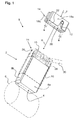
- Figs. 1 and 2 show a carbon brush 2 of a universal motor, not shown.
- This has amaschinetechniksstirnseite 4, which contacts a commutator 6 of the universal motor in operation.
- the carbon brush 2 four side surfaces 8a, 8b, 8c, 8d and a Beaufschlagungsstirnseite 10, which is acted upon in operation with the interposition of a bottom 12 of a cup-shaped cap 14 by a contact force F.
- the carbon brush 2 is biased along a carbon guide 16 against the commutator 6.
- the cup-shaped protective cap 14 is made of polyamide 6.6, for example, and has four side walls 18a, 18b, 18c, 18d extending from the bottom 12, which delimit a receptacle 20 with a receiving opening 22 arranged on a side of the protective cap 14 facing away from the bottom 12.
- an end area 24 of the carbon brush 2 facing the loading end face 10 is moved into the receptacle 20 via this receiving opening 22, the end area 24 having a slightly larger cross section than the receptacle 20.
- the protective cap which has a certain elasticity, is clamped to the end region 24 by a hoop stress generated during attachment.
- the side walls 18a, 18b, 18c, 18d and the bottom 12 act here as wear protection. On the one hand reduce the side walls 18a, 18b, 18c, 18d caused by friction on the carbon guide abrasion at the end portion 24, which occurs in particular due to operational vibration in the presence of coal dust and detached carbon particles.
- a sufficiently stable connection between the cap 14 and the carbon brush 2 and a closed shape thereof is on the End region 24 a over the four side surfaces 8a, 8b, 8c, 8d circumferentially recessed recess 26 provided, which is opposite to a in Fig. 1 indicated by dotted line original shape formed.
- the recess 26 at each of the four side surfaces 8a, 8b, 8c, 8d each have a thickness d which corresponds to a thickness s of the respectively associated side walls 18a, 18b, 18c, 18d.
- a receiving slot 28 is inserted, which is formed parallel to a Aufsteckraum R and opened to the receiving opening 20.
- the protective cap 14 can also be plugged onto the end region 24 via a strand 30 which emerges laterally on the carbon brush 2.
- an adhesive 32 can be provided at the end region 24 in addition to the said clamping connection, which produces an additional adhesive bond.
Landscapes
- Motor Or Generator Current Collectors (AREA)
Abstract
Description
- Die Erfindung betrifft eine Kohlebürste eines Universalmotors, die eine Kontaktierungsstirnseite zur Kontaktierung eines Kommutators und eine von dieser abgewandte Beaufschlagungsstirnseite aufweist, an der beispielsweise ein Federdruck aufgebracht wird, um die Kohlebürste in Richtung des Kommutators vorzuspannen. Ferner weist die Kohlebürste vier Seitenflächen auf, die sich zwischen der Kontaktierungsstirnseite und der Beaufschlagungsstirnseite erstrecken. Hierbei sind Verschleissschutzmittel vorgesehen, die an einem der Beaufschlagungsstirnseite zugewandten Endbereich der Kohlebürste angeordnet sind.
- Bei derartigen Kohlebürsten kann mittels des Verschleissschutzes ein seitlicher Verschleiss an den Kohlebürsten deutlich reduziert werden. Dieser Verschleiss tritt im Betrieb infolge des Vorhandenseins von abgelösten Kohlepartikeln und der Vibrationen insbesondere zwischen den Seitenflächen und der betreffenden Kohleführung auf. Als Folge des seitlichen Verschleisses kann es zu einer ungenauen Führung der Kohlebürste in der Kohleführung und dadurch wiederum zu einer stark verkürzten Lebensdauer der Kohlebürste kommen.
- Aus der
GB 27,162 - Nachteilig an den bekannten Verschleissschutzmitteln ist, dass deren Befestigung an der Kohlebürste relativ aufwändig ist, wodurch die Herstellungskosten für die Kohlebürsten relativ hoch sind. Zudem bedingt die Art der Befestigung eine Materialschwächung der Kohlebürste, die infolge von Verschleiss über die Lebensdauer der Kohlebürste zunimmt. Dies kann wiederum zu einem Verschleiss der Kohlebürste an den Schutzplättchen führen.
- Der vorliegenden Erfindung liegt die Aufgabe zugrunde, bei einer Kohlebürste die genannten Nachteile zu vermeiden und bei geringen Herstellungskosten einen ausreichenden Verschleissschutz zu gewährleisten.
- Erfindungsgemäss wird die Aufgabe dadurch gelöst, dass die Verschleissschutzmittel an einer topfförmigen Schutzkappe ausgebildet sind. Eine derartige Schutzkappe kann einfach auf die betreffende Kohlebürste aufgesteckt werden und ermöglicht somit eine kostengünstige Herstellung der Kohlebürste.
- In einer besonders bevorzugten Ausführungsform umschliesst die Schutzkappe alle vier Seitenflächen im Wesentlichen vollständig. Hierdurch kann bei geeigneter Dimensionierung der Schutzkappe gegenüber der Kohlebürste eine Ringspannung aufgebaut werden, die die Schutzkappe an der Kohlebürste sichert.
- Vorteilhafterweise ist an dem der Beaufschlagungsstirnseite zugewandten Endbereich an den vier Seitenflächen eine umlaufende Aussparung zur teilweisen Aufnahme der Schutzkappe vorgesehen. Auf diese Weise kann die Schutzkappe durch Formschluss exakt gegenüber der Kohlebürste positioniert werden.
- Bevorzugterweise weist die Aussparung an jeder Seitenfläche eine Dicke auf, die einer Wandstärke einer der jeweiligen Seitenfläche zugeordneten Seitenwand der Schutzkappe entspricht. Auf diese Weise schliesst die Oberfläche der Schutzkappe bündig mit den Seitenflächen der Kohlebürste ab, um eine exakte Führung entlang der Kohleführung zu gewährleisten.
- Vorteilhafterweise ist an einer der Seitenwände ein Aufnahmeschlitz vorgesehen, der in Richtung einer Aufnahmeöffnung der Schutzkappe geöffnet ist. Hierdurch kann die Schutzkappe ohne Probleme über eine an der Kohlebürste seitlich austretende Litze geschoben werden. Ferner wird durch einen derartigen Aufnahmeschlitz eine gewisse Elastizität der Schutzkappe hergestellt, die eine besonders einfache Montage ermöglicht.
- Ferner ist es besonders günstig, wenn an den Seitenflächen zwischen diesen und der Schutzkappe ein Klebstoff vorgesehen ist. Hierdurch wird die Schutzkappe besonders stabil an der Kohlebürste festgelegt.
- Zudem ist die Schutzkappe vorteilhafterweise aus Polyamid 6.6 hergestellt, wodurch eine ausreichende Abriebsfestigkeit der Verschleissschutzmittel gewährleistet werden kann.
- Die Erfindung wird nachstehend anhand eines Ausführungsbeispieles näher erläutert. Es zeigen:
- Fig. 1
- eine perspektivische Ansicht einer Kontaktierungsstirnseite einer Kohlebürste mit getrennter Schutzkappe und
- Fig. 2
- eine perspektivische Ansicht einer Beaufschlagungsstirnseite der Kohlebürste in Richtung II aus Fig. 1.
- Die Fig. 1 und 2 zeigen eine Kohlebürste 2 eines nicht näher dargestellten Universalmotors. Diese weist eine Kontaktierungsstirnseite 4 auf, die im Betrieb einen Kommutator 6 des Universalmotors kontaktiert. Ferner weist die Kohlebürste 2 vier Seitenflächen 8a, 8b, 8c, 8d und eine Beaufschlagungsstirnseite 10 auf, die im Betrieb unter Zwischenlage eines Bodens 12 einer topfförmigen Schutzkappe 14 von einer Anpresskraft F beaufschlagt ist. Durch diese Anpresskraft F wird die Kohlebürste 2 entlang einer Kohleführung 16 gegen den Kommutator 6 vorgespannt.
- Die topfförmige Schutzkappe 14 ist beispielsweise aus Polyamid 6.6 hergestellt und weist vier vom Boden 12 abgehende Seitenwände 18a, 18b, 18c, 18d auf, die eine Aufnahme 20 mit einer an einer vom Boden 12 abgewandten Seite der Schutzkappe 14 angeordneten Aufnahmeöffnung 22 begrenzen. Über diese Aufnahmeöffnung 22 wird beim Aufstecken der Schutzkappe 14 ein der Beaufschlagungsstirnseite 10 zugewandter Endbereich 24 der Kohlebürste 2 in die Aufnahme 20 hinein verlegt, wobei der Endbereich 24 einen geringfügig grösseren Querschnitt als die Aufnahme 20 aufweist. Hierdurch wird die Schutzkappe, die eine gewisse Elastizität aufweist, durch eine beim Aufstecken erzeugte Ringspannung an dem Endbereich 24 festgeklemmt.
- Die Seitenwände 18a, 18b, 18c, 18d sowie der Boden 12 fungieren hierbei als Verschleissschutzmittel. Dabei reduzieren einerseits die Seitenwände 18a, 18b, 18c, 18d den durch Reibung an der Kohleführung verursachten Abrieb am Endbereich 24, der insbesondere in Folge von betriebsbedingten Vibrationen bei Präsenz von Kohlestaub und abgelösten Kohlepartikeln auftritt.
- Um hierbei einerseits eine ausreichend stabile Verbindung zwischen der Schutzkappe 14 und der Kohlebürste 2 sowie eine geschlossene Form derselben zu erzielen, ist an dem Endbereich 24 eine über die vier Seitenflächen 8a, 8b, 8c, 8d hinweg umlaufend eingelassene Aussparung 26 vorgesehen, die gegenüber einer in Fig. 1 mit strichpunktierter Linie dargestellten ursprünglichen Form, ausgebildet ist. Dabei weist die Aussparung 26 an jeder der vier Seitenflächen 8a, 8b, 8c, 8d jeweils eine Dicke d auf, die einer Stärke s der jeweilig zugeordneten Seitenwände 18a, 18b, 18c, 18d entspricht. Hierdurch wird ein bündiges Abschliessen der Seitenflächen 8a, 8b, 8c, 8d der Kohlebürste mit den Seitenwänden 18a, 18b, 18c, 18d der Schutzkappe 14 erzielt.
- Ferner ist an der Seitenwand 18a ein Aufnahmeschlitz 28 eingelassen, der parallel zu einer Aufsteckrichtung R ausgebildet und zu der Aufnahmeöffnung 20 hin geöffnet ist. Hierdurch kann die Schutzkappe 14 auch über eine an der Kohlebürste 2 seitlich austretende Litze 30 auf den Endbereich 24 aufgesteckt werden.
- Um die Stabilität der Verbindung zwischen der Kohlebürste 2 und der Schutzkappe 14 weiter zu erhöhen, kann an dem Endbereich 24 neben der genannten Klemmverbindung ein Klebstoff 32 vorgesehen werden, der eine zusätzlich wirkende Klebeverbindung erzeugt.
Claims (7)
- Kohlebürste (2)
mit einer Kontaktierungsstirnseite (4) und einer von dieser abgewandten Beaufschlagungsstirnseite (10) sowie vier Seitenflächen (8a, 8b, 8c, 8d),
wobei Verschleissschutzmittel vorgesehen sind, die an einem der Beaufschlagungsstirnseite (10) zugewandten Endbereich (24) angeordnet sind,
dadurch gekennzeichnet, dass die Verschleissschutzmittel als topfförmige Schutzkappe (14) ausgebildet sind. - Kohlebürste nach Anspruch 1, dadurch gekennzeichnet, dass sich die Schutzkappe (14) über alle vier Seitenflächen (8a, 8b, 8c, 8d) umfänglich erstreckt.
- Kohlebürste nach Anspruch 1 oder 2, dadurch gekennzeichnet, dass an dem der Beaufschlagungsstirnseite (10) zugewandten Endbereich (24) an den vier Seitenflächen (8a, 8b, 8c, 8d) eine umlaufende Aussparung (26) zur teilweisen Aufnahme der Schutzkappe (14) vorgesehen ist.
- Kohlebürste nach Anspruch 3, dadurch gekennzeichnet, dass die Aussparung (26) an jeder Seitenfläche (8a, 8b, 8c, 8d) eine Dicke (d) aufweist, die einer Wandstärke (s) einer der jeweiligen Seitenfläche (8a, 8b, 8c, 8d) zugeordneten Seitenwand (18a, 18b, 18c, 18d) der Schutzkappe (14) entspricht.
- Kohlebürste nach Anspruch 3, dadurch gekennzeichnet, dass an einer der Seitenwände (8a, 8b, 8c, 8d) ein Aufnahmeschlitz (28) vorgesehen ist, der in Richtung einer Aufnahmeöffnung (22) der Schutzkappe (14) geöffnet ist.
- Kohlebürste nach einem der Ansprüche 1 bis 5, dadurch gekennzeichnet, dass an den Seitenflächen (8a, 8b, 8c, 8d) zwischen diesen und der Schutzkappe (14) ein Klebstoff (32) vorgesehen ist.
- Kohlebürste nach einem der Ansprüche 1 bis 6, dadurch gekennzeichnet, dass die Schutzkappe (14) aus Polyamid 6.6 hergestellt ist.
Applications Claiming Priority (1)
| Application Number | Priority Date | Filing Date | Title |
|---|---|---|---|
| DE102006000496A DE102006000496A1 (de) | 2006-09-29 | 2006-09-29 | Kohlebürste mit Verschleissschutzmitteln |
Publications (2)
| Publication Number | Publication Date |
|---|---|
| EP1906494A1 true EP1906494A1 (de) | 2008-04-02 |
| EP1906494B1 EP1906494B1 (de) | 2011-04-20 |
Family
ID=38754522
Family Applications (1)
| Application Number | Title | Priority Date | Filing Date |
|---|---|---|---|
| EP07116744A Active EP1906494B1 (de) | 2006-09-29 | 2007-09-19 | Kohlebürste mit Verschleissschutzmitteln |
Country Status (4)
| Country | Link |
|---|---|
| US (1) | US20080100170A1 (de) |
| EP (1) | EP1906494B1 (de) |
| CN (1) | CN101154785A (de) |
| DE (2) | DE102006000496A1 (de) |
Families Citing this family (5)
| Publication number | Priority date | Publication date | Assignee | Title |
|---|---|---|---|---|
| CN103427278A (zh) * | 2012-05-18 | 2013-12-04 | 海门市华联电碳有限公司 | 曲线锯用碳刷 |
| CN104339265A (zh) * | 2014-08-26 | 2015-02-11 | 江苏京创先进电子科技有限公司 | 切割机主轴碳刷防磨损系统及其工作过程 |
| US9853407B2 (en) | 2015-09-08 | 2017-12-26 | Helwig Carbon Products, Inc. | Brush assembly |
| USD795192S1 (en) * | 2015-09-08 | 2017-08-22 | Helwig Carbon Products, Inc. | Brush assembly |
| CN113824272A (zh) * | 2021-08-27 | 2021-12-21 | 东风电驱动系统有限公司 | 一种电刷防护板和调节器装配工装及方法 |
Citations (6)
| Publication number | Priority date | Publication date | Assignee | Title |
|---|---|---|---|---|
| GB191027162A (en) | 1910-11-22 | 1911-10-05 | Morgan Crucible Co | Improvements in or connected with Carbon Brushes for Dynamo Electric Machines. |
| US1573402A (en) * | 1924-05-19 | 1926-02-16 | Nat Carbon Co Inc | Conductive brush and method of securing attachments thereto |
| US2358958A (en) | 1943-03-20 | 1944-09-26 | John T Brown | Collector brush clip |
| US2472540A (en) | 1945-03-14 | 1949-06-07 | Jim C Meador | Piston ring |
| US2473540A (en) * | 1944-02-26 | 1949-06-21 | Miller Tobias | Electrical motor and dynamo brush |
| US3791331A (en) | 1972-05-05 | 1974-02-12 | E Dilley | Electric outboard motor |
Family Cites Families (23)
| Publication number | Priority date | Publication date | Assignee | Title |
|---|---|---|---|---|
| US661669A (en) * | 1898-07-22 | 1900-11-13 | Gen Electric | Connecting conductors to carbon brushes. |
| US996475A (en) * | 1909-09-11 | 1911-06-27 | Gen Electric | Brush for dynamo-electric machines. |
| US1433686A (en) * | 1919-11-04 | 1922-10-31 | Corliss Carbon Company | Device for attaching conductors to brushes |
| US1433687A (en) * | 1922-04-03 | 1922-10-31 | Corliss Carbon Company Inc | Device for attaching conductors to brushes |
| US1579097A (en) * | 1925-04-14 | 1926-03-30 | Harry H Erdman | Commutator and slip-ring brush shunt connection |
| US1844174A (en) * | 1928-05-18 | 1932-02-09 | Horace D Munday | Brush holder device for truing commutators |
| US2864019A (en) * | 1957-05-10 | 1958-12-09 | Gordon James | Electrical brush holder |
| US3355611A (en) * | 1965-06-11 | 1967-11-28 | Union Carbide Corp | Brush clip assembly |
| US3439206A (en) * | 1965-08-31 | 1969-04-15 | Richard T Grannells | Brush for electrical devices |
| DE7010521U (de) * | 1970-03-21 | 1971-08-26 | Bosch Gmbh Robert | Abschaltkohlebuerste. |
| JPS5234004U (de) * | 1975-09-02 | 1977-03-10 | ||
| DE2817317A1 (de) * | 1978-04-20 | 1979-10-25 | Siemens Ag | Stromuebertragungsbuerste |
| US4329612A (en) * | 1980-05-23 | 1982-05-11 | Ingersoll-Rand Company | Brushholder |
| JPS6048364U (ja) * | 1983-09-06 | 1985-04-05 | 三菱電機株式会社 | ブラシホルダ |
| US4847528A (en) * | 1987-02-10 | 1989-07-11 | Mitsuba Electric Manufacturing Co., Ltd. | Plastic molding on penetration metal, particularly on motor end plate |
| US5208499A (en) * | 1992-01-16 | 1993-05-04 | Carbone-Lorraine Of North America | EMI/RFI suppressing brush holder assembly for electric machines |
| FR2690791B1 (fr) * | 1992-05-04 | 1994-06-17 | Lorraine Carbone | Balai pour moteur electrique a sensibilite aux vibrations attenuee. |
| US5945755A (en) * | 1994-09-20 | 1999-08-31 | Denso Corporation | Starter with housing for cantilever-mounting on engine |
| DE19654352A1 (de) * | 1996-12-24 | 1998-06-25 | Bosch Gmbh Robert | Kollektormaschine mit Gehäusekontaktierung |
| JP3660598B2 (ja) * | 2001-02-06 | 2005-06-15 | マブチモーター株式会社 | 小型モータのブラシ保持方法及び装置 |
| US7249757B2 (en) * | 2002-09-26 | 2007-07-31 | Japan Servo Co., Ltd. | Brush type small motor having non-linear spring device |
| US6707220B1 (en) * | 2003-02-12 | 2004-03-16 | Siemens Vdo Automotive, Inc. | Electric motor brush holder for suppressing audible and electromagnetic noise |
| US7423359B2 (en) * | 2004-06-18 | 2008-09-09 | Moog Inc. | Fluid-dispensing reservoir for large-diameter slip rings |
-
2006
- 2006-09-29 DE DE102006000496A patent/DE102006000496A1/de not_active Withdrawn
-
2007
- 2007-09-19 DE DE502007006981T patent/DE502007006981D1/de active Active
- 2007-09-19 EP EP07116744A patent/EP1906494B1/de active Active
- 2007-09-24 CN CNA2007101618459A patent/CN101154785A/zh active Pending
- 2007-09-27 US US11/904,788 patent/US20080100170A1/en not_active Abandoned
Patent Citations (6)
| Publication number | Priority date | Publication date | Assignee | Title |
|---|---|---|---|---|
| GB191027162A (en) | 1910-11-22 | 1911-10-05 | Morgan Crucible Co | Improvements in or connected with Carbon Brushes for Dynamo Electric Machines. |
| US1573402A (en) * | 1924-05-19 | 1926-02-16 | Nat Carbon Co Inc | Conductive brush and method of securing attachments thereto |
| US2358958A (en) | 1943-03-20 | 1944-09-26 | John T Brown | Collector brush clip |
| US2473540A (en) * | 1944-02-26 | 1949-06-21 | Miller Tobias | Electrical motor and dynamo brush |
| US2472540A (en) | 1945-03-14 | 1949-06-07 | Jim C Meador | Piston ring |
| US3791331A (en) | 1972-05-05 | 1974-02-12 | E Dilley | Electric outboard motor |
Also Published As
| Publication number | Publication date |
|---|---|
| DE502007006981D1 (de) | 2011-06-01 |
| US20080100170A1 (en) | 2008-05-01 |
| CN101154785A (zh) | 2008-04-02 |
| DE102006000496A1 (de) | 2008-04-03 |
| EP1906494B1 (de) | 2011-04-20 |
Similar Documents
| Publication | Publication Date | Title |
|---|---|---|
| DE102006046908A1 (de) | Wischblattrastvorrichtung | |
| DE2431425C2 (de) | Spannschiene für Kettenantriebe | |
| EP1906494B1 (de) | Kohlebürste mit Verschleissschutzmitteln | |
| EP2049367A1 (de) | Vorrichtung zum halten einer kamera an einem träger | |
| DE102008001956A1 (de) | Wischblatt | |
| WO2005073039A2 (de) | Scheibenwischvorrichtung, insbesondere für ein kraftfahrzeug | |
| DE102011005167A1 (de) | Wischblattadapter, insbesondere für eine Kraftfahrzeugwischvorrichtung | |
| DE202005019070U1 (de) | Sägeblatt-Klemmmechanismus für ein Elektro-Werkzeug | |
| EP3198165A1 (de) | Bremsbelaghalterung einer scheibenbremse, scheibenbremse und bremsbelag | |
| DE2505879C3 (de) | Teilbelag-Scheibenbremse, insbesondere für Kraftfahrzeuge | |
| EP0101546B1 (de) | Elektromotor, insbesondere zum Antreiben von Hilfsaggregaten in Kraftfahrzeugen | |
| EP1253676A2 (de) | Elektrischer Steckverbinder | |
| DE102011089922A1 (de) | Wischblattvorrichtung | |
| EP2726336A1 (de) | Wischvorrichtung | |
| DE102006035440A1 (de) | Bürstenhalter | |
| EP0599033A1 (de) | Bremsbelag mit Verschleisswarnvorrichtung | |
| EP2742568A1 (de) | Bürstenbremse | |
| DE102016206159A1 (de) | Wischarmvorrichtung | |
| DE102015201358A1 (de) | Leuchtenanordnung für ein Kraftfahrzeug und Heckspoiler | |
| EP2651708B1 (de) | Wischblattvorrichtung | |
| EP3950438B1 (de) | Umlenker mit federelement | |
| EP2190702B1 (de) | Dämpfungselement | |
| DE102019211621A1 (de) | Scheibenwischervorrichtung | |
| DE10061797B4 (de) | Leuchte | |
| DE102005036138A1 (de) | Sensorhalterung zur Halterung eines Sensors an einem Fahrzeugteil |
Legal Events
| Date | Code | Title | Description |
|---|---|---|---|
| PUAI | Public reference made under article 153(3) epc to a published international application that has entered the european phase |
Free format text: ORIGINAL CODE: 0009012 |
|
| AK | Designated contracting states |
Kind code of ref document: A1 Designated state(s): AT BE BG CH CY CZ DE DK EE ES FI FR GB GR HU IE IS IT LI LT LU LV MC MT NL PL PT RO SE SI SK TR |
|
| AX | Request for extension of the european patent |
Extension state: AL BA HR MK YU |
|
| 17P | Request for examination filed |
Effective date: 20081002 |
|
| 17Q | First examination report despatched |
Effective date: 20081106 |
|
| AKX | Designation fees paid |
Designated state(s): CH DE FR GB IT LI |
|
| GRAP | Despatch of communication of intention to grant a patent |
Free format text: ORIGINAL CODE: EPIDOSNIGR1 |
|
| GRAC | Information related to communication of intention to grant a patent modified |
Free format text: ORIGINAL CODE: EPIDOSCIGR1 |
|
| GRAS | Grant fee paid |
Free format text: ORIGINAL CODE: EPIDOSNIGR3 |
|
| GRAA | (expected) grant |
Free format text: ORIGINAL CODE: 0009210 |
|
| AK | Designated contracting states |
Kind code of ref document: B1 Designated state(s): CH DE FR GB IT LI |
|
| REG | Reference to a national code |
Ref country code: GB Ref legal event code: FG4D Free format text: NOT ENGLISH |
|
| REG | Reference to a national code |
Ref country code: CH Ref legal event code: EP |
|
| REF | Corresponds to: |
Ref document number: 502007006981 Country of ref document: DE Date of ref document: 20110601 Kind code of ref document: P |
|
| REG | Reference to a national code |
Ref country code: DE Ref legal event code: R096 Ref document number: 502007006981 Country of ref document: DE Effective date: 20110601 |
|
| PLBE | No opposition filed within time limit |
Free format text: ORIGINAL CODE: 0009261 |
|
| STAA | Information on the status of an ep patent application or granted ep patent |
Free format text: STATUS: NO OPPOSITION FILED WITHIN TIME LIMIT |
|
| 26N | No opposition filed |
Effective date: 20120123 |
|
| REG | Reference to a national code |
Ref country code: DE Ref legal event code: R097 Ref document number: 502007006981 Country of ref document: DE Effective date: 20120123 |
|
| REG | Reference to a national code |
Ref country code: FR Ref legal event code: PLFP Year of fee payment: 10 |
|
| REG | Reference to a national code |
Ref country code: FR Ref legal event code: PLFP Year of fee payment: 11 |
|
| REG | Reference to a national code |
Ref country code: FR Ref legal event code: PLFP Year of fee payment: 12 |
|
| P01 | Opt-out of the competence of the unified patent court (upc) registered |
Effective date: 20230830 |
|
| PGFP | Annual fee paid to national office [announced via postgrant information from national office to epo] |
Ref country code: DE Payment date: 20240918 Year of fee payment: 18 |
|
| PGFP | Annual fee paid to national office [announced via postgrant information from national office to epo] |
Ref country code: GB Payment date: 20240919 Year of fee payment: 18 |
|
| PGFP | Annual fee paid to national office [announced via postgrant information from national office to epo] |
Ref country code: FR Payment date: 20240924 Year of fee payment: 18 |
|
| PGFP | Annual fee paid to national office [announced via postgrant information from national office to epo] |
Ref country code: IT Payment date: 20240924 Year of fee payment: 18 |
|
| PGFP | Annual fee paid to national office [announced via postgrant information from national office to epo] |
Ref country code: CH Payment date: 20241001 Year of fee payment: 18 |
|
| REG | Reference to a national code |
Ref country code: CH Ref legal event code: H13 Free format text: ST27 STATUS EVENT CODE: U-0-0-H10-H13 (AS PROVIDED BY THE NATIONAL OFFICE) Effective date: 20260504 |