EP1905751B1 - Composite sintered body - Google Patents
Composite sintered body Download PDFInfo
- Publication number
- EP1905751B1 EP1905751B1 EP06756456.7A EP06756456A EP1905751B1 EP 1905751 B1 EP1905751 B1 EP 1905751B1 EP 06756456 A EP06756456 A EP 06756456A EP 1905751 B1 EP1905751 B1 EP 1905751B1
- Authority
- EP
- European Patent Office
- Prior art keywords
- boron nitride
- cubic boron
- binder
- sintered body
- composite sintered
- Prior art date
- Legal status (The legal status is an assumption and is not a legal conclusion. Google has not performed a legal analysis and makes no representation as to the accuracy of the status listed.)
- Active
Links
Images
Classifications
-
- C—CHEMISTRY; METALLURGY
- C04—CEMENTS; CONCRETE; ARTIFICIAL STONE; CERAMICS; REFRACTORIES
- C04B—LIME, MAGNESIA; SLAG; CEMENTS; COMPOSITIONS THEREOF, e.g. MORTARS, CONCRETE OR LIKE BUILDING MATERIALS; ARTIFICIAL STONE; CERAMICS; REFRACTORIES; TREATMENT OF NATURAL STONE
- C04B35/00—Shaped ceramic products characterised by their composition; Ceramics compositions; Processing powders of inorganic compounds preparatory to the manufacturing of ceramic products
- C04B35/515—Shaped ceramic products characterised by their composition; Ceramics compositions; Processing powders of inorganic compounds preparatory to the manufacturing of ceramic products based on non-oxide ceramics
- C04B35/58—Shaped ceramic products characterised by their composition; Ceramics compositions; Processing powders of inorganic compounds preparatory to the manufacturing of ceramic products based on non-oxide ceramics based on borides, nitrides, i.e. nitrides, oxynitrides, carbonitrides or oxycarbonitrides or silicides
- C04B35/583—Shaped ceramic products characterised by their composition; Ceramics compositions; Processing powders of inorganic compounds preparatory to the manufacturing of ceramic products based on non-oxide ceramics based on borides, nitrides, i.e. nitrides, oxynitrides, carbonitrides or oxycarbonitrides or silicides based on boron nitride
- C04B35/5831—Shaped ceramic products characterised by their composition; Ceramics compositions; Processing powders of inorganic compounds preparatory to the manufacturing of ceramic products based on non-oxide ceramics based on borides, nitrides, i.e. nitrides, oxynitrides, carbonitrides or oxycarbonitrides or silicides based on boron nitride based on cubic boron nitrides or Wurtzitic boron nitrides, including crystal structure transformation of powder
-
- B—PERFORMING OPERATIONS; TRANSPORTING
- B23—MACHINE TOOLS; METAL-WORKING NOT OTHERWISE PROVIDED FOR
- B23B—TURNING; BORING
- B23B27/00—Tools for turning or boring machines; Tools of a similar kind in general; Accessories therefor
- B23B27/14—Cutting tools of which the bits or tips or cutting inserts are of special material
-
- C—CHEMISTRY; METALLURGY
- C04—CEMENTS; CONCRETE; ARTIFICIAL STONE; CERAMICS; REFRACTORIES
- C04B—LIME, MAGNESIA; SLAG; CEMENTS; COMPOSITIONS THEREOF, e.g. MORTARS, CONCRETE OR LIKE BUILDING MATERIALS; ARTIFICIAL STONE; CERAMICS; REFRACTORIES; TREATMENT OF NATURAL STONE
- C04B35/00—Shaped ceramic products characterised by their composition; Ceramics compositions; Processing powders of inorganic compounds preparatory to the manufacturing of ceramic products
- C04B35/622—Forming processes; Processing powders of inorganic compounds preparatory to the manufacturing of ceramic products
- C04B35/626—Preparing or treating the powders individually or as batches ; preparing or treating macroscopic reinforcing agents for ceramic products, e.g. fibres; mechanical aspects section B
- C04B35/62605—Treating the starting powders individually or as mixtures
- C04B35/62645—Thermal treatment of powders or mixtures thereof other than sintering
- C04B35/6265—Thermal treatment of powders or mixtures thereof other than sintering involving reduction or oxidation
-
- C—CHEMISTRY; METALLURGY
- C04—CEMENTS; CONCRETE; ARTIFICIAL STONE; CERAMICS; REFRACTORIES
- C04B—LIME, MAGNESIA; SLAG; CEMENTS; COMPOSITIONS THEREOF, e.g. MORTARS, CONCRETE OR LIKE BUILDING MATERIALS; ARTIFICIAL STONE; CERAMICS; REFRACTORIES; TREATMENT OF NATURAL STONE
- C04B35/00—Shaped ceramic products characterised by their composition; Ceramics compositions; Processing powders of inorganic compounds preparatory to the manufacturing of ceramic products
- C04B35/622—Forming processes; Processing powders of inorganic compounds preparatory to the manufacturing of ceramic products
- C04B35/626—Preparing or treating the powders individually or as batches ; preparing or treating macroscopic reinforcing agents for ceramic products, e.g. fibres; mechanical aspects section B
- C04B35/62605—Treating the starting powders individually or as mixtures
- C04B35/62645—Thermal treatment of powders or mixtures thereof other than sintering
- C04B35/6268—Thermal treatment of powders or mixtures thereof other than sintering characterised by the applied pressure or type of atmosphere, e.g. in vacuum, hydrogen or a specific oxygen pressure
-
- C—CHEMISTRY; METALLURGY
- C04—CEMENTS; CONCRETE; ARTIFICIAL STONE; CERAMICS; REFRACTORIES
- C04B—LIME, MAGNESIA; SLAG; CEMENTS; COMPOSITIONS THEREOF, e.g. MORTARS, CONCRETE OR LIKE BUILDING MATERIALS; ARTIFICIAL STONE; CERAMICS; REFRACTORIES; TREATMENT OF NATURAL STONE
- C04B35/00—Shaped ceramic products characterised by their composition; Ceramics compositions; Processing powders of inorganic compounds preparatory to the manufacturing of ceramic products
- C04B35/622—Forming processes; Processing powders of inorganic compounds preparatory to the manufacturing of ceramic products
- C04B35/626—Preparing or treating the powders individually or as batches ; preparing or treating macroscopic reinforcing agents for ceramic products, e.g. fibres; mechanical aspects section B
- C04B35/63—Preparing or treating the powders individually or as batches ; preparing or treating macroscopic reinforcing agents for ceramic products, e.g. fibres; mechanical aspects section B using additives specially adapted for forming the products, e.g.. binder binders
- C04B35/6303—Inorganic additives
-
- C—CHEMISTRY; METALLURGY
- C04—CEMENTS; CONCRETE; ARTIFICIAL STONE; CERAMICS; REFRACTORIES
- C04B—LIME, MAGNESIA; SLAG; CEMENTS; COMPOSITIONS THEREOF, e.g. MORTARS, CONCRETE OR LIKE BUILDING MATERIALS; ARTIFICIAL STONE; CERAMICS; REFRACTORIES; TREATMENT OF NATURAL STONE
- C04B35/00—Shaped ceramic products characterised by their composition; Ceramics compositions; Processing powders of inorganic compounds preparatory to the manufacturing of ceramic products
- C04B35/622—Forming processes; Processing powders of inorganic compounds preparatory to the manufacturing of ceramic products
- C04B35/626—Preparing or treating the powders individually or as batches ; preparing or treating macroscopic reinforcing agents for ceramic products, e.g. fibres; mechanical aspects section B
- C04B35/63—Preparing or treating the powders individually or as batches ; preparing or treating macroscopic reinforcing agents for ceramic products, e.g. fibres; mechanical aspects section B using additives specially adapted for forming the products, e.g.. binder binders
- C04B35/632—Organic additives
- C04B35/634—Polymers
- C04B35/63404—Polymers obtained by reactions only involving carbon-to-carbon unsaturated bonds
- C04B35/63444—Nitrogen-containing polymers, e.g. polyacrylamides, polyacrylonitriles, polyvinylpyrrolidone [PVP], polyethylenimine [PEI]
-
- C—CHEMISTRY; METALLURGY
- C04—CEMENTS; CONCRETE; ARTIFICIAL STONE; CERAMICS; REFRACTORIES
- C04B—LIME, MAGNESIA; SLAG; CEMENTS; COMPOSITIONS THEREOF, e.g. MORTARS, CONCRETE OR LIKE BUILDING MATERIALS; ARTIFICIAL STONE; CERAMICS; REFRACTORIES; TREATMENT OF NATURAL STONE
- C04B35/00—Shaped ceramic products characterised by their composition; Ceramics compositions; Processing powders of inorganic compounds preparatory to the manufacturing of ceramic products
- C04B35/622—Forming processes; Processing powders of inorganic compounds preparatory to the manufacturing of ceramic products
- C04B35/64—Burning or sintering processes
- C04B35/645—Pressure sintering
-
- C—CHEMISTRY; METALLURGY
- C04—CEMENTS; CONCRETE; ARTIFICIAL STONE; CERAMICS; REFRACTORIES
- C04B—LIME, MAGNESIA; SLAG; CEMENTS; COMPOSITIONS THEREOF, e.g. MORTARS, CONCRETE OR LIKE BUILDING MATERIALS; ARTIFICIAL STONE; CERAMICS; REFRACTORIES; TREATMENT OF NATURAL STONE
- C04B2235/00—Aspects relating to ceramic starting mixtures or sintered ceramic products
- C04B2235/02—Composition of constituents of the starting material or of secondary phases of the final product
- C04B2235/30—Constituents and secondary phases not being of a fibrous nature
- C04B2235/32—Metal oxides, mixed metal oxides, or oxide-forming salts thereof, e.g. carbonates, nitrates, (oxy)hydroxides, chlorides
- C04B2235/3217—Aluminum oxide or oxide forming salts thereof, e.g. bauxite, alpha-alumina
-
- C—CHEMISTRY; METALLURGY
- C04—CEMENTS; CONCRETE; ARTIFICIAL STONE; CERAMICS; REFRACTORIES
- C04B—LIME, MAGNESIA; SLAG; CEMENTS; COMPOSITIONS THEREOF, e.g. MORTARS, CONCRETE OR LIKE BUILDING MATERIALS; ARTIFICIAL STONE; CERAMICS; REFRACTORIES; TREATMENT OF NATURAL STONE
- C04B2235/00—Aspects relating to ceramic starting mixtures or sintered ceramic products
- C04B2235/02—Composition of constituents of the starting material or of secondary phases of the final product
- C04B2235/30—Constituents and secondary phases not being of a fibrous nature
- C04B2235/38—Non-oxide ceramic constituents or additives
- C04B2235/3804—Borides
- C04B2235/3813—Refractory metal borides
-
- C—CHEMISTRY; METALLURGY
- C04—CEMENTS; CONCRETE; ARTIFICIAL STONE; CERAMICS; REFRACTORIES
- C04B—LIME, MAGNESIA; SLAG; CEMENTS; COMPOSITIONS THEREOF, e.g. MORTARS, CONCRETE OR LIKE BUILDING MATERIALS; ARTIFICIAL STONE; CERAMICS; REFRACTORIES; TREATMENT OF NATURAL STONE
- C04B2235/00—Aspects relating to ceramic starting mixtures or sintered ceramic products
- C04B2235/02—Composition of constituents of the starting material or of secondary phases of the final product
- C04B2235/30—Constituents and secondary phases not being of a fibrous nature
- C04B2235/38—Non-oxide ceramic constituents or additives
- C04B2235/3852—Nitrides, e.g. oxynitrides, carbonitrides, oxycarbonitrides, lithium nitride, magnesium nitride
- C04B2235/3856—Carbonitrides, e.g. titanium carbonitride, zirconium carbonitride
-
- C—CHEMISTRY; METALLURGY
- C04—CEMENTS; CONCRETE; ARTIFICIAL STONE; CERAMICS; REFRACTORIES
- C04B—LIME, MAGNESIA; SLAG; CEMENTS; COMPOSITIONS THEREOF, e.g. MORTARS, CONCRETE OR LIKE BUILDING MATERIALS; ARTIFICIAL STONE; CERAMICS; REFRACTORIES; TREATMENT OF NATURAL STONE
- C04B2235/00—Aspects relating to ceramic starting mixtures or sintered ceramic products
- C04B2235/02—Composition of constituents of the starting material or of secondary phases of the final product
- C04B2235/30—Constituents and secondary phases not being of a fibrous nature
- C04B2235/38—Non-oxide ceramic constituents or additives
- C04B2235/3852—Nitrides, e.g. oxynitrides, carbonitrides, oxycarbonitrides, lithium nitride, magnesium nitride
- C04B2235/3865—Aluminium nitrides
- C04B2235/3869—Aluminium oxynitrides, e.g. AlON, sialon
-
- C—CHEMISTRY; METALLURGY
- C04—CEMENTS; CONCRETE; ARTIFICIAL STONE; CERAMICS; REFRACTORIES
- C04B—LIME, MAGNESIA; SLAG; CEMENTS; COMPOSITIONS THEREOF, e.g. MORTARS, CONCRETE OR LIKE BUILDING MATERIALS; ARTIFICIAL STONE; CERAMICS; REFRACTORIES; TREATMENT OF NATURAL STONE
- C04B2235/00—Aspects relating to ceramic starting mixtures or sintered ceramic products
- C04B2235/02—Composition of constituents of the starting material or of secondary phases of the final product
- C04B2235/30—Constituents and secondary phases not being of a fibrous nature
- C04B2235/38—Non-oxide ceramic constituents or additives
- C04B2235/3852—Nitrides, e.g. oxynitrides, carbonitrides, oxycarbonitrides, lithium nitride, magnesium nitride
- C04B2235/3886—Refractory metal nitrides, e.g. vanadium nitride, tungsten nitride
-
- C—CHEMISTRY; METALLURGY
- C04—CEMENTS; CONCRETE; ARTIFICIAL STONE; CERAMICS; REFRACTORIES
- C04B—LIME, MAGNESIA; SLAG; CEMENTS; COMPOSITIONS THEREOF, e.g. MORTARS, CONCRETE OR LIKE BUILDING MATERIALS; ARTIFICIAL STONE; CERAMICS; REFRACTORIES; TREATMENT OF NATURAL STONE
- C04B2235/00—Aspects relating to ceramic starting mixtures or sintered ceramic products
- C04B2235/02—Composition of constituents of the starting material or of secondary phases of the final product
- C04B2235/30—Constituents and secondary phases not being of a fibrous nature
- C04B2235/40—Metallic constituents or additives not added as binding phase
- C04B2235/402—Aluminium
-
- C—CHEMISTRY; METALLURGY
- C04—CEMENTS; CONCRETE; ARTIFICIAL STONE; CERAMICS; REFRACTORIES
- C04B—LIME, MAGNESIA; SLAG; CEMENTS; COMPOSITIONS THEREOF, e.g. MORTARS, CONCRETE OR LIKE BUILDING MATERIALS; ARTIFICIAL STONE; CERAMICS; REFRACTORIES; TREATMENT OF NATURAL STONE
- C04B2235/00—Aspects relating to ceramic starting mixtures or sintered ceramic products
- C04B2235/02—Composition of constituents of the starting material or of secondary phases of the final product
- C04B2235/50—Constituents or additives of the starting mixture chosen for their shape or used because of their shape or their physical appearance
- C04B2235/54—Particle size related information
- C04B2235/5418—Particle size related information expressed by the size of the particles or aggregates thereof
- C04B2235/5436—Particle size related information expressed by the size of the particles or aggregates thereof micrometer sized, i.e. from 1 to 100 micron
-
- C—CHEMISTRY; METALLURGY
- C04—CEMENTS; CONCRETE; ARTIFICIAL STONE; CERAMICS; REFRACTORIES
- C04B—LIME, MAGNESIA; SLAG; CEMENTS; COMPOSITIONS THEREOF, e.g. MORTARS, CONCRETE OR LIKE BUILDING MATERIALS; ARTIFICIAL STONE; CERAMICS; REFRACTORIES; TREATMENT OF NATURAL STONE
- C04B2235/00—Aspects relating to ceramic starting mixtures or sintered ceramic products
- C04B2235/02—Composition of constituents of the starting material or of secondary phases of the final product
- C04B2235/50—Constituents or additives of the starting mixture chosen for their shape or used because of their shape or their physical appearance
- C04B2235/54—Particle size related information
- C04B2235/5418—Particle size related information expressed by the size of the particles or aggregates thereof
- C04B2235/5445—Particle size related information expressed by the size of the particles or aggregates thereof submicron sized, i.e. from 0,1 to 1 micron
-
- C—CHEMISTRY; METALLURGY
- C04—CEMENTS; CONCRETE; ARTIFICIAL STONE; CERAMICS; REFRACTORIES
- C04B—LIME, MAGNESIA; SLAG; CEMENTS; COMPOSITIONS THEREOF, e.g. MORTARS, CONCRETE OR LIKE BUILDING MATERIALS; ARTIFICIAL STONE; CERAMICS; REFRACTORIES; TREATMENT OF NATURAL STONE
- C04B2235/00—Aspects relating to ceramic starting mixtures or sintered ceramic products
- C04B2235/70—Aspects relating to sintered or melt-casted ceramic products
- C04B2235/74—Physical characteristics
- C04B2235/78—Grain sizes and shapes, product microstructures, e.g. acicular grains, equiaxed grains, platelet-structures
- C04B2235/786—Micrometer sized grains, i.e. from 1 to 100 micron
-
- C—CHEMISTRY; METALLURGY
- C04—CEMENTS; CONCRETE; ARTIFICIAL STONE; CERAMICS; REFRACTORIES
- C04B—LIME, MAGNESIA; SLAG; CEMENTS; COMPOSITIONS THEREOF, e.g. MORTARS, CONCRETE OR LIKE BUILDING MATERIALS; ARTIFICIAL STONE; CERAMICS; REFRACTORIES; TREATMENT OF NATURAL STONE
- C04B2235/00—Aspects relating to ceramic starting mixtures or sintered ceramic products
- C04B2235/70—Aspects relating to sintered or melt-casted ceramic products
- C04B2235/80—Phases present in the sintered or melt-cast ceramic products other than the main phase
- C04B2235/85—Intergranular or grain boundary phases
-
- C—CHEMISTRY; METALLURGY
- C04—CEMENTS; CONCRETE; ARTIFICIAL STONE; CERAMICS; REFRACTORIES
- C04B—LIME, MAGNESIA; SLAG; CEMENTS; COMPOSITIONS THEREOF, e.g. MORTARS, CONCRETE OR LIKE BUILDING MATERIALS; ARTIFICIAL STONE; CERAMICS; REFRACTORIES; TREATMENT OF NATURAL STONE
- C04B2235/00—Aspects relating to ceramic starting mixtures or sintered ceramic products
- C04B2235/70—Aspects relating to sintered or melt-casted ceramic products
- C04B2235/96—Properties of ceramic products, e.g. mechanical properties such as strength, toughness, wear resistance
- C04B2235/9607—Thermal properties, e.g. thermal expansion coefficient
-
- C—CHEMISTRY; METALLURGY
- C04—CEMENTS; CONCRETE; ARTIFICIAL STONE; CERAMICS; REFRACTORIES
- C04B—LIME, MAGNESIA; SLAG; CEMENTS; COMPOSITIONS THEREOF, e.g. MORTARS, CONCRETE OR LIKE BUILDING MATERIALS; ARTIFICIAL STONE; CERAMICS; REFRACTORIES; TREATMENT OF NATURAL STONE
- C04B2235/00—Aspects relating to ceramic starting mixtures or sintered ceramic products
- C04B2235/70—Aspects relating to sintered or melt-casted ceramic products
- C04B2235/96—Properties of ceramic products, e.g. mechanical properties such as strength, toughness, wear resistance
- C04B2235/9669—Resistance against chemicals, e.g. against molten glass or molten salts
- C04B2235/9692—Acid, alkali or halogen resistance
-
- Y—GENERAL TAGGING OF NEW TECHNOLOGICAL DEVELOPMENTS; GENERAL TAGGING OF CROSS-SECTIONAL TECHNOLOGIES SPANNING OVER SEVERAL SECTIONS OF THE IPC; TECHNICAL SUBJECTS COVERED BY FORMER USPC CROSS-REFERENCE ART COLLECTIONS [XRACs] AND DIGESTS
- Y10—TECHNICAL SUBJECTS COVERED BY FORMER USPC
- Y10T—TECHNICAL SUBJECTS COVERED BY FORMER US CLASSIFICATION
- Y10T428/00—Stock material or miscellaneous articles
- Y10T428/24—Structurally defined web or sheet [e.g., overall dimension, etc.]
- Y10T428/24802—Discontinuous or differential coating, impregnation or bond [e.g., artwork, printing, retouched photograph, etc.]
- Y10T428/24893—Discontinuous or differential coating, impregnation or bond [e.g., artwork, printing, retouched photograph, etc.] including particulate material
Definitions
- the present invention relates to a composite sintered body containing at least cubic boron nitride and a binder, and more specifically to a composite sintered body particularly suitably used in an application such as a cutting tool.
- a high-hardness sintered body mainly composed of cubic boron nitride has conventionally been used in an application such as a cutting tool.
- Such a sintered body is normally implemented by a composite sintered body containing cubic boron nitride and a binder mainly aiming to maintain strength of the former.
- a sintered body having a sea-island structure, in which cubic boron nitride particles (islands) are dispersed in a continuous phase (sea) of the binder Japanese Patent Laying-Open No. 53-077811 (Patent Document 1) and Japanese Patent Laying-Open No. 10-182242 (Patent Document 2)
- Patent Document 1 Japanese Patent Laying-Open No. 53-077811
- Patent Document 2 Japanese Patent Laying-Open No. 10-182242
- Such a sea-island structure has been adopted, aiming to promote a sintered state of cubic boron nitride particles to thereby improve strength such as toughness, by not allowing contact between the cubic boron nitride particles but separating the cubic boron nitride particles from each other in order to avoid an unsintered state of cubic boron nitride caused at a contact portion where the cubic boron nitride particles physically contact with each other.
- Patent Document 7 a sintered body in which a continuous structure of cubic boron nitride particles is implemented by bonding the particles to each other has been known (United States Patent No. 5639285 Specification (Patent Document 7)).
- the cubic boron nitride particles exhibit the continuous structure, an effect to improve heat resistance, that is, an effect to suppress increase in the temperature at the cutting edge, can be expected to some extent.
- the binder is scattered discontinuously around the continuous structure of the cubic boron nitride particles, the sintered body is poor in chipping resistance or crater wear resistance, and consequently it is poor in toughness.
- Such a defect is particularly problematic in cutting a high-hardness material such as quenched steel, because exposure of the cutting edge of the cutting tool to a high temperature of 600°C or higher is more likely.
- improvement in productivity has recently been demanded in a cutting process operation. With the increase in a cutting speed or feed rate, the temperature at the cutting edge is often raised to a temperature around 1000°C. Solution of the problem described above has thus been desired.
- JP 08126903 relates to a cutting tool made of cubic boron nitride super high pressure sintered material excellent in wear resistance.
- EP 1378497 relates to a sintered compact for use in machining chemically reactive materials.
- EP 1547990 relates to high-strength, high thermally conductive sintered compacts of cubic boron nitride.
- An object of the present invention is to provide a sintered body of cubic boron nitride highly attaining improvement in both heat resistance and toughness.
- the present invention provides a composite sintered body according to claim 1 of the claims appended hereto.
- the present inventors have fundamentally reexamined the conventional premise that at least one of cubic boron nitride and the binder should be implemented as a discontinuous structure in the composite sintered body containing cubic boron nitride.
- the present inventors have conceived that both heat resistance and toughness may be improved if both of cubic boron nitride and the binder are implemented as the continuous structures.
- the present invention was completed based on this concept and further study.
- a composite sintered body according to the present invention contains at least cubic boron nitride and a binder.
- Cubic boron nitride has a continuous structure as a result of bonding of a plurality of cubic boron nitride particles to each other.
- the binder has a continuous structure as a result of bonding of a plurality of binder particles to each other, that are present in a region except for a bonding interface where the cubic boron nitride particles are bonded to each other.
- the binder at least contains at least one of a compound and a solid solution of any one element or two or more elements of Ti, Zr, Hf, V, and Cr and any one element or two or more elements of nitrogen, carbon, boron, and oxygen, and an aluminum compound.
- the binder may be present at the bonding interface where the cubic boron nitride particles are bonded to each other at existence probability of at most 60%, and the binder may be present as a part of the continuous structure as a result of its continuity to the continuous structure of the binder particles or as a discontinuous structure isolated from the continuous structure of the binder particles.
- the binder may have composition containing at least Ti or Al at the bonding interface where the cubic boron nitride particles are bonded to each other.
- the binder may not be present at the bonding interface where the cubic boron nitride particles are bonded to each other.
- the composite sintered body may have transverse rupture strength after acid treatment of at least 1gf/mm 2 to at most 70kgf/mm 2 .
- a compound other than cubic boron nitride and Al 2 O 3 is not substantially detected in X-ray diffraction measurement after acid treatment.
- the cubic boron nitride may be contained in the composite sintered body by at least 60 volume % to at most 85 volume %, and the cubic boron nitride particle may have an average particle size of at least 2 ⁇ m to at most 10 ⁇ m.
- the composite sintered body has thermal conductivity of at least 60W/(m ⁇ K) to at most 150W/(m ⁇ K).
- the aluminum compound is implemented by a compound of aluminum, oxygen and nitrogen and/or a compound of aluminum, oxygen, nitrogen, and boron, the aluminum compound has an average particle size of at least 50nm to at most 1 ⁇ m, and a ratio of the aluminum compound in the binder is at least 5 volume % to at most 30 volume %.
- the composite sintered body may have thermal conductivity of at least 70W/(m ⁇ K) to at most 150W/(m ⁇ K).
- a cutting tool according to the present invention may at least partially contain the composite sintered body described above.
- the composite sintered body according to the present invention highly attains improvement in both heat resistance and toughness.
- the cutting tool at least partially containing the composite sintered body according to the present invention can suitably be used in high-efficiency process or high-speed interrupted cutting of high-hardness steel.
- the composite sintered body according to the present invention contains at least cubic boron nitride and the binder, and it can suitably be used in an application such as a cutting tool. It is noted that the composite sintered body according to the present invention may contain other components or an inevitable impurity, so long as it contains at least cubic boron nitride and the binder.
- cubic boron nitride contained in the composite sintered body according to the present invention has previously been used in an application such as the cutting tool, for its excellent hardness and thermal conductivity.
- cubic boron nitride has a continuous structure as will be described later, and cubic boron nitride is contained in the composite sintered body by at least 60 volume % to at most 85 volume %. More preferably, the lower limit of the content is set to at least 65 volume % and further preferably to at least 72 volume %. More preferably, the upper limit of the content is set to at most 80 volume % and further preferably to at most 77 volume %.
- the ratio of cubic boron nitride is less than 60 volume %, sufficient contact between the cubic boron nitride particles may not be attained. In such a case, as the continuous structure which will be described later may not sufficiently be obtained, increase in the temperature at the cutting edge cannot sufficiently be suppressed, and hence an effect of sufficient improvement in heat resistance may not be obtained. On the other hand, if the ratio of cubic boron nitride exceeds 85 volume %, an amount of the binder present in the sintered body, which will be described later, relatively decreases, and wear resistance may remarkably be lowered.
- volume percentage can be achieved by setting volume percentage of the cubic boron nitride powder used in manufacturing the composite sintered body to a value in the above-described range (that is, from at least 60 volume % to at most 85 volume %).
- the volume percentage can be measured by subjecting the composite sintered body to quantitative analysis using ICP (inductively coupled plasma spectrochemical analysis) or observation using an SEM (scanning electron microscope) or a TEM (transmission electron microscope).
- the cubic boron nitride particle has an average particle size of at least 2 ⁇ m to at most 10 ⁇ m. If the average particle size is smaller than 2 ⁇ m, a surface area of the cubic boron nitride particle becomes greater.
- the number of bonded portions between the cubic boron nitride particles (sometimes called neck growth) excessively increases, and the binder which will be described later enters a multiple point such as a triple point or a quadruple point among the cubic boron nitride particles (referring not to the contact interface between the cubic boron nitride particles but to a gap between the cubic boron nitride particles; hereinafter simply denoted as the triple point), and the existence probability of the discontinuously isolated binder increases.
- the thermal conductivity may be lowered.
- strength of the composite sintered body is lowered.
- the cutting edge may be chipped in a severe cutting environment.
- the lower limit of the average particle size is set to at least 2.5 ⁇ m and further preferably to at least 2.8 ⁇ m.
- the upper limit of the average particle size is set to at most 6 ⁇ m and further preferably to at most 3.8 ⁇ m.
- the binder according to the present invention mainly attains a function to hold the cubic boron nitride described above, and a composition thereof is according to claim 1 of the claims appended hereto.
- the binder contains at least one of a compound and a solid solution of any one element or two or more elements of Ti, Zr, Hf, V, and Cr and any one element or two or more elements of nitrogen, carbon, boron, and oxygen, and an aluminum compound.
- This compound or solid solution of these elements can achieve high bonding strength with the cubic boron nitride and it is chemically stable. Therefore, the compound or solid solution is excellent in wear resistance and preferable.
- any one or more of a nitride, a carbide, a carbonitride, a boride, an oxide, and a solid solution of any one element or two or more elements of Ti, Zr, Hf, V, and Cr may be employed as the compound or solid solution, and more preferably, at least one of a nitride, a boride, an oxide, and a solid solution of any one element or two or more elements of Ti, Zr, Hf, V, and Cr may be employed.
- This compound or solid solution may be employed because it can attain particularly high bonding strength with cubic boron nitride.
- Examples of the aluminum compound include AlN, AlB 2 , Al 2 O 3 , and the like.
- the aluminum compound is implemented by a compound of aluminum, oxygen and nitrogen and/or a compound of aluminum, oxygen, nitrogen, and boron.
- the aluminum compound has an average particle size of at least 50nm to at most 1 ⁇ m, and a ratio of the aluminum compound in the binder (the total amount) is set to at least 5 volume % to at most 30 volume %.
- AlN When AlN is used as the aluminum compound, improvement in heat resistance can be expected, because AlN is a material excellent in thermal conductivity, as used in a heat sink. Meanwhile, AlN has low strength. Therefore, if a large amount of AlN is present in the composite sintered body, cracking originates from AlN and toughness is lowered.
- Al 2 O 3 In the case of employing Al 2 O 3 , as can be seen from the fact that Al 2 O 3 alone is used as a ceramic tool, Al 2 O 3 has high hardness and is stable at a high temperature, whereas it is poor in thermal conductivity. Therefore, use of a large amount of Al 2 O 3 leads to lowering in thermal conductivity of the composite sintered body and to lowering in heat resistance.
- the compound of aluminum, oxygen and nitrogen and/or the compound of aluminum, oxygen, nitrogen, and boron are superior to AlN and Al 2 O 3 in strength and superior to Al 2 O 3 in thermal conductivity. Therefore, if the compound having the average particle size of at least 50nm to at most 1 ⁇ m is contained in the binder by at least 5 volume % to at most 30 volume %, the binder excellent in strength and thermal conductivity can be provided, which contributes to improvement in toughness and heat resistance of the composite sintered body. Therefore, particularly if such an aluminum compound is present in a manner satisfying the conditions above, the composite sintered body can have thermal conductivity, which will be described later, of at least 70W/(m ⁇ K) to at most 150W/(m ⁇ K).
- the compound of aluminum, oxygen, nitrogen, and boron is selectively present around the cubic boron nitride particles. Therefore, it is estimated that cubic boron nitride supplies nitrogen and boron composing the compound, which seems to serve to strengthen bonding between cubic boron nitride and the binder. It is thus estimated that presence of the compound contributes to significant improvement in toughness of the composite sintered body.
- the average particle size is smaller than 50nm, an effect of improvement in thermal conductivity may be lowered due to increase in the interface. Meanwhile, if the average particle size exceeds 1 ⁇ m, strength may be lowered. Preferably, the average particle size is set to at least 80nm to at most 0.7 ⁇ m. If the ratio described above is smaller than 5 volume %, an effect of improvement in strength and thermal conductivity as described above is not obtained and an effect in improvement in bonding strength with cubic boron nitride may not sufficiently be obtained. If the ratio exceeds 30 volume %, the content of a binder component having relatively good toughness other than the aluminum compound is lowered and toughness of the composite sintered body may be lowered.
- the ratio is set to at least 10 volume % to at most 27 volume %.
- the volume percentage can be measured in quantitative analysis using ICP (inductively coupled plasma spectrochemical analysis) or observation using an SEM (scanning electron microscope) or a TEM (transmission electron microscope).
- these compounds may simply be expressed as general formula Al X O Y N Z and general formula Al S B T O U N V .
- cubic boron nitride has the continuous structure as a result of bonding of a plurality of cubic boron nitride particles to each other
- the binder has the continuous structure as a result of bonding of a plurality of binder particles to each other, that are present in a region except for the bonding interface where the cubic boron nitride particles are bonded to each other.
- the composite sintered body is manufactured by sintering cubic boron nitride and the binder, and both of these have the continuous structure as described above. Therefore, the cubic boron nitride and the binder are firmly bonded to each other.
- the composite sintered body according to the present invention adopts such a continuous structure. Therefore, even if the composite sintered body is used in the cutting tool to which a severe cutting condition (such as high-efficiency process, high-speed interrupted cutting or the like of the high-hardness steel described above) is applied, the composite sintered body can exhibit sufficient heat resistance and toughness and provide satisfactory tool life.
- a severe cutting condition such as high-efficiency process, high-speed interrupted cutting or the like of the high-hardness steel described above
- the binder or the like does not fall off from the composite sintered body even under the condition as in interrupted cutting where sudden temperature change is repeated, and hence toughness can drastically be improved.
- Such falling off as in the conventional example is considered to be attributable to difference in the coefficient of thermal expansion between cubic boron nitride and the binder as described already. Even if a small cracking due to difference in the coefficient of thermal expansion between cubic boron nitride and the binder takes place at the time of change in the temperature, falling off is effectively prevented because the binder has the continuous structure.
- cubic boron nitride has the continuous structure, excellent characteristic of high hardness and high thermal conductivity specific to cubic boron nitride can sufficiently be exhibited, thus showing excellent toughness and heat resistance. It is considered that, as the continuous structure of cubic boron nitride exhibits an excellent heat dissipation effect, temperature increase is suppressed and heat resistance is significantly improved, and that as development of small cracking that has occurred within the composite sintered body is prevented by the continuous structure of cubic boron nitride, toughness may further be improved.
- the composite sintered body according to the present invention has thermal conductivity of at least 60W/(m ⁇ K) to at most 150W/(m ⁇ K). As the thermal conductivity is higher, temperature increase at the cutting edge during cutting is suppressed. Therefore, higher thermal conductivity is preferred. If thermal conductivity exceeds 150W/(m ⁇ K), however, bonded area of the cubic boron nitride particles excessively increases. Consequently, the binder enters the triple point of the cubic boron nitride particles, and existence probability of the discontinuously isolated binder increases, which is not preferred. It is noted that thermal conductivity can be calculated by measuring thermal diffusivity with a laser flash or xenon flash thermal diffusivity measurement apparatus, based on specific heat and density.
- the expression "has the continuous structure as a result of bonding of a plurality of cubic boron nitride particles to each other” refers to a structure completely different from the sea-island structure (Patent Documents 1, 2) in which the cubic boron nitride particles are dispersed in the continuous binder phase as in the conventional example, and refers to the continuous structure exhibited as a result of bonding of the cubic boron nitride particles to each other.
- the continuous structure is considered to exhibit a three-dimensional structure in which cubic boron nitride particles are three-dimensionally bonded to each other.
- the expression "has the continuous structure as a result of bonding of a plurality of binder particles to each other, that are present in a region except for the bonding interface where the cubic boron nitride particles are bonded to each other” refers to a structure completely different from the structure (Patent Document 7) in which the binder is discontinuously scattered around the structure obtained as a result of bonding of the cubic boron nitride particles to each other as in the conventional example, and refers to the continuous structure exhibited as a result of bonding of the binder particles to each other.
- the continuous structure is considered to exhibit a three-dimensional structure in which binder particles are three-dimensionally bonded to each other.
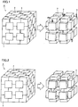
- the reason why the region where the binder particles constituting the continuous structure are present is defined as the region except for the bonding interface where the cubic boron nitride particles are bonded to each other is to clarify that the composite sintered body of the subject application includes a structure in each manner as described below. Specifically, if the binder is present at the bonding interface where such cubic boron nitride particles are bonded to each other, the manner of presence of the binder includes any one or both of a manner of presence as a part of the continuous structure as a result of its continuity to the continuous structure of the binder particles and a manner of presence as the discontinuous structure isolated from the continuous structure of the binder particles as shown in Fig. 1 . In addition, it is also clarified that, if the binder is not present at the bonding interface between such cubic boron nitride particles, the composite sintered body of the subject application may also encompass such a manner that the binder is not present,
- Fig. 1 is a partial perspective view of a composite sintered body 4 conceptually illustrating a manner in which the binder is present as the discontinuous structure isolated from the continuous structure of binder particles 2 at the bonding interface where cubic boron nitride particles 1 are bonded to each other.
- Fig. 1 shows, on the right with respect to the central arrow, the manner in which cubic boron nitride particles 1 are conceptually removed from composite sintered body 4 shown on the left, and shows on the right that the binder at the bonding interface is present as an isolated binder 3.
- the binder is present at the bonding interface between the cubic boron nitride particles, preferably, the binder is present at the existence probability of at most 60%, and the binder is present as a part of the continuous structure as a result of its continuity to the continuous structure of the binder particles or as the discontinuous structure isolated from the continuous structure of the binder particles.
- the binder at the bonding interface where the cubic boron nitride particles are bonded to each other has composition containing at least Ti or Al. It is most preferable from a point of view of thermal conductivity that the cubic boron nitride particles can directly be bonded to each other firmly, without including the binder at the bonding interface.
- the existence probability of the binder at the bonding interface between the cubic boron nitride particles is set to 60% or lower, lowering in thermal conductivity can be minimized by ensuring continuity between the cubic boron nitride particles.
- the binder is composed of a component containing Ti or Al element having high affinity to oxygen, the component serves as a getter of adsorbed oxygen that has remained at the bonding interface between the cubic boron nitride particles during sintering.
- the existence probability of 60% or lower means that the binder is detected at measurement points accounting for at most 60% of all measurement points when AES (Auger electron spectroscopy) analysis or EDS (energy dispersive X-ray spectroscopy) analysis is conducted at a plurality of measurement points at one bonding interface between the cubic boron nitride particles.
- AES Alger electron spectroscopy
- EDS energy dispersive X-ray spectroscopy
- the expression “the cubic boron nitride particles or the binder particles are bonded to each other” means that, though crystal orientation of each particle may be different from each other, the particles are firmly bonded to each other at the bonding interface between the particles as a result of some kind of chemical bond or physical bond, or involvement of a third compound.
- the expression “the cubic boron nitride and the binder are bonded to each other” in the description above means that the cubic boron nitride and the binder are firmly bonded to each other as a result of some kind of chemical bond or physical bond, or involvement of a third compound, as in the case of bonding between the particles above.
- the continuous structure obtained as a result of bonding of a plurality of cubic boron nitride particles to each other and the continuous structure obtained as a result of bonding of a plurality of binder particles to each other, that are present in a region except for the bonding interface where the cubic boron nitride particles are bonded to each other, can be confirmed by subjecting the composite sintered body to acid treatment, thereafter subjecting the treated body to XRD (X-ray diffraction) measurement, visually observing appearance of the treated body, and measuring transverse rupture strength.
- XRD X-ray diffraction
- the acid treatment refers to a treatment in which a mixed acid obtained by mixing concentrated nitric acid (60%), distilled water and concentrated hydrofluoric acid (47%) at a volume ratio of 2:2:1 and the composite sintered body cut into a prescribed size (in a rectangular shape of length 6mm ⁇ width 3mm ⁇ thickness 0.5mm) are placed in an airtight container and the composite sintered body is dissolved under pressure for 48 hours at a temperature of 140°C.
- the "treated body" subjected to “acid treatment” is in turn subjected to XRD measurement. If the binder component is not detected in the measurement, it indicates that the binder has completely been removed from the composite sintered body, and the continuous structure of the binder is confirmed.
- the mixed acid serves to selectively dissolve the binder and remove solely the binder. If the binder is implemented as the discontinuous structure instead of the continuous structure according to the subject application, it is considered that the isolated binder structured like an island and surrounded by the cubic boron nitride is present as shown in Fig. 2 and the isolated binder is not dissolved and removed in the acid treatment but remains in the treated body. Consequently, the binder component is detected in the XRD measurement.
- Fig. 2 is a partial perspective view of composite sintered body 4 conceptually illustrating a manner in which the binder is present as the discontinuous structure isolated from the continuous structure of binder particles 2 at the triple point among cubic boron nitride particles 1. Namely, Fig. 2 shows, on the right with respect to the central arrow, the manner in which cubic boron nitride particles 1 are conceptually removed from composite sintered body 4 shown on the left, and shows on the right that binder particles 2 is present as isolated binder 3.
- the binder may be detected as the binder component in the X-ray diffraction measurement. Accordingly, if the binder component is detected in this manner, origin of the binder component, that is, whether the binder is present as the discontinuous structure at the bonding interface between the cubic boron nitride particles ( Fig. 1 ) or as the isolated, discontinuous structure like an island surrounded by the cubic boron nitride particles ( Fig. 2 ), can be determined by measuring the transverse rupture strength after the acid treatment which will be described later. Detailed description will be provided later.
- the cubic boron nitride does not have the continuous structure as above but has the discontinuous structure as in the conventional example, the treated body becomes powdery and collapses after the acid treatment, and exhibits appearance completely different from the composite sintered body prior to treatment.
- the cubic boron nitride has the continuous structure as above, the treated body maintains the original shape exhibited prior to the acid treatment.
- the expression "maintains the original shape” means that the original body is not divided into two or more parts in a handling under the load lower than 1gf/mm 2 in a normal filtration operation or the like. In this manner, the continuous structure of cubic boron nitride can be confirmed by visually observing the appearance of the treated body after the acid treatment.
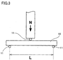
- transverse rupture strength of the treated body is measured.
- a condition that three points in a treated body 10 in a rectangular shape (length 6mm ⁇ width 3mm ⁇ thickness 0.5mm) are supported by three posts 11 (diameter 2mm) and span L is set to 4mm is adopted.
- a load N is applied to an intermediate portion of span L, and load N at the time when treated body 10 is broken is measured as the transverse rupture strength.
- the transverse rupture strength attains to a value from at least 1gf/mm 2 to at most 70kgf/mm 2 .
- the high transverse rupture strength is shown because the cubic boron nitride has the continuous structure as described above, and if the cubic boron nitride is implemented as the discontinuous structure, the transverse rupture strength is lower than 1gf/mm 2 . Here, higher transverse rupture strength is preferred, and it is not necessary to define the upper limit thereof. If the transverse rupture strength exceeds 70kgf/mm 2 , however, the number of bonding interfaces present between the cubic boron nitride particles becomes excessively large, and it is more likely that the binder is discontinuously taken in the triple point of the cubic boron nitride particles.
- the transverse rupture strength attains to a value exceeding 70kgf/mm 2 .
- the transverse rupture strength attains to 70kgf/mm 2 or lower in spite of detection of the binder component after the acid treatment, it indicates that the binder is present as the discontinuous structure at the bonding interface between the cubic boron nitride particles ( Fig. 1 ).
- the composite sintered body according to the present invention can be manufactured in the following manner. Initially, cubic boron nitride powders and binder powders that are raw material powders are mixed. The mixture is sintered under the condition of pressure and temperature at which cubic boron nitride is not converted to hexagonal boron nitride, or the binder component is externally infiltrated into the mixture during sintering under the condition of pressure and temperature at which cubic boron nitride is not converted to hexagonal boron nitride.
- the mixed powders when the mixed powders are filled in a capsule made of refractory metal (for example, a capsule made of Mo (molybdenum)) for fabricating a sintered body, the mixed powders are filled such that they are sandwiched by metal foils made of an alloy of Ti and Al, and then sintered.
- the metal foil serves to implement the binder and has a melting point not higher than the sintering temperature. Accordingly, the metal foil turns to liquid during sintering and permeates through the mixed powders, whereby both of the cubic boron nitride particles and the binders can attain the continuous structure.
- the composite sintered body according to the present invention achieving further improved continuity between the cubic boron nitride particles and between the binder particles can be manufactured.
- the binder present at the triple point of the cubic boron nitride particles is not isolated and continuity of the structure of the binder is enhanced.
- Conditions such as pressure history and temperature history should preferably be controlled such that a prescribed condition for pressure and temperature at which cubic boron nitride is thermodynamically stable is set during sintering.
- a general condition for obtaining a sintered cubic boron nitride body will be described.
- pressure is applied to the mixed powders of cubic boron nitride and the binder as described above at a low temperature so as to promote consolidation, and thereafter the mixed powders are sintered at a raised temperature. For example, after the pressure is raised to 4 to 6GPa at a room temperature, the temperature is raised to 1300 to 1800°C. Sintering is performed with the highest temperature being maintained.
- the binder having low hardness is mainly broken during application of pressure, and the broken, fine binder slides in between the cubic boron nitride particles.
- the cubic boron nitride particles having high hardness and less likely to be broken than the binder are arranged to surround the binder, thus forming the triple point. Then, the mixed powders are sintered by heating while consolidation in that small region no longer proceeds.
- the following conditions are adopted as specific conditions for a sintering method of the subject application.
- the pressure and the temperature are once raised to 2 to 5GPa and 1000 to 1500°C respectively, at which cubic boron nitride is thermodynamically stable (pressurization and temperature increase are simultaneously performed), and this pressure and temperature condition is maintained for 1 to 5 minutes.
- Sintering thus initially proceeds simultaneously with consolidation, in a portion where the cubic boron nitride particles come in contact with each other.
- the binder is softened and plastically deforms along with temperature increase, and that fluidity is enhanced. Therefore, it is considered that the binder slides into the gap (permeates) between the cubic boron nitride particles even when the cubic boron nitride particles are arranged to surround the binder, and thus the continuous structure is maintained.
- bonding strength between the cubic boron nitride particles, between the binder particles, and between the cubic boron nitride particles and the binder particles can further be strengthened by reforming the surface of the cubic boron nitride particles and the binder particles.
- surface reformation is performed, for example, through plasma treatment in hydrogen or heat treatment in an ammonia atmosphere, of raw material powders before sintering.
- the cutting tool according to the present invention at least partially contains the composite sintered body described above.
- a cutting-edge nose portion serving as a central point of application in cutting may be formed from the composite sintered body.
- a cutting edge portion may be formed from the composite sintered body, or the entire surface of a rake face including the cutting edge portion may be formed from the composite sintered body.
- the cutting tool in its entirety may be formed from the composite sintered body.
- the structure of the cutting tool according to the present invention is not particularly limited, so long as the structure at least partially contains the composite sintered body.
- any conventionally known base material used as the base material for the cutting tool of this type can implement the remaining part.
- a base material for example, hardmetal (such as WC-based hardmetal, a material containing Co in addition to WC, or a material to which carbonitride of Ti, Ta, Nb, or the like is further added), cermet (mainly composed of TiC, TiN, TiCN, or the like), high-speed steel, ceramics (titanium carbide, silicon carbide, silicon nitride, aluminum nitride, aluminum oxide, and a mixture thereof), sintered diamond, sintered silicon nitride, or the like is employed.
- hardmetal such as WC-based hardmetal, a material containing Co in addition to WC, or a material to which carbonitride of Ti, Ta, Nb, or the like is further added
- cermet mainly composed of TiC, TiN, TiCN, or the like
- high-speed steel ceramics (titanium carbide, silicon carbide, silicon nitride, aluminum nitride, aluminum oxide, and a mixture thereof),
- the raw material powders for the binder obtained as above and the cubic boron nitride powders having an average particle size of 3.8 ⁇ m were homogenously mixed using the ball mill, at such a blending ratio that the cubic boron nitride powders accounted for 70 volume %. Thereafter, the mixed powders were held in the vacuum furnace for 20 minutes at a temperature of 900°C for degassing.
- the mixed powders degassed as described above were sandwiched between the metal foils made of TiAl alloy (Ti (50 atomic %) Al (50 atomic %)) and filled in the capsule made of molybdenum (Mo). Thereafter, the pressure and the temperature were simultaneously raised to 3GPa and 1200°C using an ultra-high pressure apparatus respectively, and the mixed powders were maintained for 2 minutes under this pressure and temperature condition.
- TiAl alloy Ti (50 atomic %) Al (50 atomic %)
- Mo molybdenum
- the composite sintered body according to the present invention at least containing cubic boron nitride and the binder was thus manufactured.
- the composition of the composite sintered body was specified in XRD measurement (for the sake of convenience, denoted as initial XRD measurement) and thermal conductivity thereof was measured. Measurement of thermal conductivity was performed before the acid treatment which will be described later. Specifically, after the composite sintered body obtained as above was formed in a shape of isosceles triangle having a vertex angle of 80°, a base of 4mm and a thickness of 1mm, thermal diffusivity was measured with a laser flash thermal diffusivity measurement apparatus, and thermal conductivity was calculated based on specific heat and density.
- the composite sintered body was subjected to TEM (transmission electron microscope) observation, and EDS analysis and AES analysis, so as to conduct element analysis at the bonding interface between the cubic boron nitride particles, thus calculating the composition (type of the element) and the existence probability of the binder present at the bonding interface.
- Table 1 shows the result. It is noted that, in Table 1, TiN (Ti X N Y above is simply denoted as TiN; denoted similarly hereinafter), TiB 2 , AlN, and AlB 2 other than cubic boron nitride are components composing the binder. Though these components are different from the composition of the raw material powders for the binder above, it is considered to be attributable to chemical reaction to cubic boron nitride during sintering.
- the composite sintered body according to the present invention manufactured as above was formed in a rectangular shape having length 6mm ⁇ width 3mm ⁇ thickness 0.5mm
- the composite sintered body was subjected to acid treatment (as described above, the treatment in which the mixed acid obtained by mixing concentrated nitric acid (60%), distilled water and concentrated hydrofluoric acid (47%) at a volume ratio of 2:2:1 was used and dissolution under pressure was performed for 48 hours at a temperature of 140°C).
- XRD measurement of the treated body subjected to acid treatment in this manner was performed to specify the composition after acid treatment, and appearance was visually observed. Table 1 below shows the result.
- the cutting tool was fabricated using the composite sintered body manufactured as above (before acid treatment). Specifically, the composite sintered body manufactured as above was brazed to a base material made of hardmetal and formed in a prescribed shape (ISO model No. SNGA120408), to fabricate the cutting tool. Using this cutting tool, a cutting test in which quenched steel is subjected to high-speed interrupted cutting was conducted under the conditions below, so as to determine the tool life until it is chipped. Table 1 below shows the result.
- Table 1 shows each performance obtained as a result of measurement or test as in Example 1.
- the composite sintered body according to the present invention was manufactured as in Example 1, except that blending ratio of the cubic boron nitride powders was changed to 75 volume % (Example 4) or to 65 volume % (Example 5) instead of 70 volume % in Example 1.
- Table 1 below shows each performance obtained as a result of measurement or test as in Example 1.
- the composite sintered body according to the comparative example was manufactured as in Example 1, except that the metal foil made of TiAl alloy (Ti (50 atomic %) Al (50 atomic %)) was not used in filling the capsule made of molybdenum (Mo) with the mixed powders and except that sintering was performed for 15 minutes under such a condition that the pressure was raised to 5GPa at a room temperature and thereafter the temperature was raised to 1500°C as in the conventional method, instead of the condition for sintering in Example 1.
- Table 1 below shows each performance obtained as a result of measurement or test as in Example 1.
- the composite sintered body according to the comparative example was manufactured as in Comparative Example 1, except that blending ratio of the cubic boron nitride powders was changed to 85 volume %, instead of 70 volume % in Comparative Example 1.
- Table 1 below shows each performance obtained as a result of measurement or test as in Example 1.
- a commercially available cutting tool having a shape (ISO model No. SNGA120408) the same as that of the cutting tool in Example 1 obtained by brazing the composite sintered body of cubic boron nitride to the base material made of hardmetal was prepared, and Table 1 below shows each performance obtained as a result of measurement or test as in Example 1.
- the volume percentage of cubic boron nitride in the composite sintered body was measured using the SEM (scanning electron microscope). Table 1 No.
- Example 1 70 72 Ti, Al 45 cBN, TiN, TiB 2 , AlN, AlB 2 , Al 2 O 3 cBN, Al 2 O 3 original shape maintained 10.2 [gf/mm 2 ] 6.5 minutes 2 70 63 Ti, Al 57 cBN, ZrN, ZrB 2 , AlN, AlB 2 , Al 2 O 3 cBN, Al 2 O 3 original shape maintained 5.7 [gf/mm 2 ] 3.5 minutes 3 70 66 Ti, Al 55 cBN, TiCN, TiB 2 , AlN, AlB 2 , Al 2 O 3 cBN, Al 2 O 3 original shape maintained 7.6 [gf/mm 2 ] 4.1 minutes 4 75 75 Ti, Al 50
- the fact simultaneously indicates that the binder present at the bonding interface is present as a part of the continuous structure as a result of its continuity to the continuous structure of the binder particles. This fact is also supported by the transverse rupture strength after the acid treatment that attains to a value from at least 1gf/mm 2 to at most 70kgf/mm 2 .
- Comparative Example 1 collapse of the shape was confirmed in observation of appearance after acid treatment. Therefore, this fact indicates that the cubic boron nitride particles have the discontinuous structure, not the continuous structure. Accordingly, the comparative example has lower thermal conductivity and poorer tool life in the cutting test, as compared with those in the examples. For this reason, the composition and the existence probability of the binder at the bonding interface between the cubic boron nitride particles could not be measured (therefore, denoted as "-" in Table 1).
- each composite sintered body in the examples contains cubic boron nitride having the continuous structure as a result of bonding of a plurality of cubic boron nitride particles to each other and the binder having the continuous structure as a result of bonding of a plurality of binder particles to each other, so that excellent heat resistance and toughness are both attained and hence the tool life is significantly extended.
- the cubic boron nitride powders used in Example 1 were subjected to hydrogen plasma treatment with microwave plasma for 30 minutes at a temperature of 1000°C in a hydrogen flow under a reduced pressure of 1.333 ⁇ 10 4 Pa (100torr) using a microwave reactor. Thereafter, the powders thus obtained were again stirred, and the hydrogen plasma treatment under the same condition as above was repeated five times, thus obtaining the cubic boron nitride powders having the surface treated.
- the composite sintered body according to the present invention was obtained under the manufacturing condition the same as in Example 1, except that the cubic boron nitride powders thus obtained were used instead of the cubic boron nitride powders used in Example 1.
- Table 2 below shows each performance obtained as a result of measurement or test for the composite sintered body as in Example 1.
- the cubic boron nitride powders used in Example 4 were subjected to heat treatment for 30 minutes at a temperature of 1200°C in an ammonia atmosphere, thus obtaining the cubic boron nitride powders having the surface treated.
- the composite sintered body according to the present invention was obtained under the manufacturing condition the same as in Example 4, except that the cubic boron nitride powders thus obtained were used instead of the cubic boron nitride powders used in Example 4.
- Table 2 below shows each performance obtained as a result of measurement or test for the composite sintered body as in Example 1.
- the composite sintered body according to the present invention was obtained under the manufacturing condition the same as in Example 1, except that the raw material powders for the binder and the cubic boron nitride powders having an average particle size of 3.8 ⁇ m in Example 1 were homogenously mixed using the ball mill at such a blending ratio that the cubic boron nitride powders accounted for 65 volume %, thereafter degassing was performed under the condition the same as in Example 1, and 3 mass % melamine resin powders (commercially available product) were added to the degassed, mixed powders.
- Table 2 shows each performance obtained as a result of measurement or test for the composite sintered body as in Example 1. Table 2 No.
- Example 6 70 80 Ti, Al 15 cBN, TiN, TiB 2 , AlN, AlB 2 cBN original shape maintained 12.7 [gf/mm 2 ] 7.8 minutes 7 75 88 - 0 cBN, TiN, TiB 2 , AlN, AlB 2 cBN original shape maintained 15.2 [gf/mm 2 ] 8.5 minutes 8 65 76 Ti, Al 25 cBN, TiN, TiB 2 , AlN, AlB 2 , Al 2 O 3 cBN, Al 2 O 2 original shape maintained 5.6 [gf/mm 2 ] 3.5 minutes In the table above, "cBN” represents "cubic boron nitride.”
- cubic boron nitride has the continuous structure as a result of bonding of a plurality of cubic boron nitride particles to each other
- the binder has the continuous structure as a result of bonding of a plurality of binder particles to each other.
- the cutting tool using the composite sintered bodies according to Examples 6 to 8 had the tool life further longer than the cutting tool using the composite sintered bodies according to Examples 1, 4 and 5 having corresponding contents of cubic boron nitride.
- the existence probability of the binder at the bonding interface where the cubic boron nitride particles are bonded to each other is further lower than that in the composite sintered bodies according to Examples 1, 4 and 5. Therefore, the composite sintered bodies according to Examples 6 to 8 were superior in thermal conductivity to the composite sintered bodies according to Examples 1, 4 and 5. It appears that such a result was obtained for the following reasons.
- Example 6 it is considered that oxygen was effectively removed at the surface of the cubic boron nitride powder having the surface treated in hydrogen plasma treatment and that the surface was simultaneously terminated with hydrogen group.
- the reason why the result as above was obtained is estimated as follows. Specifically, the hydrogen group present at the surface in this manner attained a catalytic function at the high temperature and high pressure, and bonding strength between the cubic boron nitride particles was further strengthened.
- Example 7 it is considered that oxygen was effectively removed at the surface of the cubic boron nitride powder having the surface treated in ammonia treatment and that the surface was simultaneously terminated with amino group.
- the reason why the result as above was obtained is estimated as follows. Specifically, the amino group present at the surface in this manner attained a catalytic function at the high temperature and high pressure, and bonding strength between the cubic boron nitride particles was further strengthened.
- Example 8 it is considered that carbon free radical (such as -CH 3 group), hydrogen free radical (such as -H group), and nitrogen free radical (such as -NH 2 group) were present around the cubic boron nitride particles, as a result of addition of 3 mass % melamine powders.
- the carbon free radical is considered to attain a function to remove an oxygen impurity such as B 2 O 3 or the like present at the surface of the cubic boron nitride particles as a result of reaction to the same, and the hydrogen free radical and the nitrogen free radical are considered to attain a catalytic function to promote polycrystallization of cubic boron nitride. It is estimated that the result as above was obtained because the bonding strength between the cubic boron nitride particles was strengthened.
- the raw material powders for the binder obtained as above and the cubic boron nitride powders having an average particle size of 2.8 ⁇ m were homogenously mixed using the ball mill, at such a blending ratio that the cubic boron nitride powders accounted for 80 volume %. Thereafter, the mixed powders were held in the vacuum furnace for 20 minutes at a temperature of 900°C for degassing.
- the mixed powders degassed as above were sandwiched between the metal foils made of TiAl alloy (Ti (50 atomic %) Al (50 atomic %)) and filled in the capsule made of molybdenum (Mo). Thereafter, the pressure and the temperature were simultaneously raised to 3.5GPa and 1200°C using an ultra-high pressure apparatus respectively, and the mixed powders were maintained for 1.5 minute under this pressure and temperature condition (first pressurization and temperature increase).
- the composite sintered body according to the present invention at least containing cubic boron nitride and the binder was thus manufactured.
- the composite sintered body was subjected to initial XRD measurement, thermal conductivity measurement (before acid treatment), XRD measurement after acid treatment, observation of appearance after acid treatment, and measurement of transverse rupture strength after acid treatment as in Example 1. Table 3 below shows the result.
- the composite sintered body according to the present invention was manufactured as in Example 9, except that blending ratio of the cubic boron nitride powders was set to 77 volume % and the powders were homogenously mixed in Example 9. Table 3 below shows each performance of the composite sintered body measured as in Example 9.
- the composite sintered body according to the present invention was manufactured as in Example 9, except that blending ratio of the cubic boron nitride powders was set to 72 volume % and the powders were homogenously mixed in Example 9. Table 3 below shows each performance of the composite sintered body measured as in Example 9.
- the composite sintered body according to the present invention was manufactured as in Example 9, except that blending ratio of the cubic boron nitride powders was set to 65 volume % and the powders were homogenously mixed in Example 9. Table 3 below shows each performance of the composite sintered body measured as in Example 9.
- the composite sintered body according to the present invention was manufactured as in Example 9, except that blending ratio of the cubic boron nitride powders was set to 65 volume %, the powders were homogenously mixed and duration in which the condition of the pressure of 6.5GPa and the temperature of 1850°C was maintained was set to 60 minutes in Example 9.
- Table 3 below shows each performance of the composite sintered body measured as in Example 9.
- the composite sintered body according to the present invention was manufactured as in Example 9, except that blending ratio of the cubic boron nitride powders was set to 65 volume %, the powders were homogenously mixed and duration in which the condition of the pressure of 6.5GPa and the temperature of 1850°C was maintained was set to 40 minutes in Example 9.
- Table 3 below shows each performance of the composite sintered body measured as in Example 9.
- the composite sintered body according to the present invention was manufactured as in Example 9, except that blending ratio of the cubic boron nitride powders was set to 65 volume %, the powders were homogenously mixed and duration in which the condition of the pressure of 6.5GPa and the temperature of 1850°C was maintained was set to 20 minutes in Example 9.
- Table 3 below shows each performance of the composite sintered body measured as in Example 9.
- the composite sintered body according to the present invention was manufactured as in Example 9, except that blending ratio of the cubic boron nitride powders was set to 65 volume %, the powders were homogenously mixed and the condition in the second pressurization and temperature increase was set to 5.5GPa and 1850°C and this condition was maintained for 10 minutes in Example 9.
- Table 3 below shows each performance of the composite sintered body measured as in Example 9.
- the composite sintered body according to the present invention was manufactured as in Example 9, except that blending ratio of the cubic boron nitride powders was set to 65 volume %, the powders were homogenously mixed, the condition in the second pressurization and temperature increase was set to 5.5GPa and 1700°C, this condition was maintained for 15 minutes in Example 9.
- Table 3 below shows each performance of the composite sintered body measured as in Example 9.
- the composite sintered body according to the present invention was manufactured as in Example 9, except that blending ratio of the cubic boron nitride powders was set to 65 volume %, the powders were homogenously mixed, the condition in the second pressurization and temperature increase was set to 5.5GPa and 1550°C, this condition was maintained for 15 minutes in Example 9.
- Table 3 below shows each performance of the composite sintered body measured as in Example 9.
- the composite sintered body according to the comparative example was manufactured as in Example 9, except that blending ratio of the cubic boron nitride powders was set to 65 volume % and the powders were homogenously mixed in Example 9, except that the metal foil made of TiAl alloy (Ti (50 atomic %) Al (50 atomic %)) for filling the capsule made of molybdenum (Mo) with the mixed powders was not used, and except that sintering was performed for 30 minutes under such a condition that the pressure was raised to 5.5GPa at a room temperature and thereafter the temperature was raised to 1550°C as in the conventional method instead of the condition for sintering in Example 9.
- Table 3 below shows each performance of the composite sintered body measured as in Example 9. Table 3 No.
- Example 9 80 150 cBN, TiN, TiB 2 , AlN, AlB 2 , Al 2 O 3 , AlON cBN, Al 2 O 3 original shape maintained 70 10 77 95 cBN, TiN, TiB 2 , AlN, AlB 2 , Al 2 O 3 , AlON cBN, Al 2 O 3 original shape maintained 10 11 72 85 cBN, TiN, TlB 2 , AlN, AlB 2 , Al 2 O 2 , AlON cBN, Al 2 O 3 original shape maintained 1 12 65 77 cBN, TiN, TiB 2 , AlN, AlB 2 , Al 2 O 3 , AlON cBN, Al 2 O 3 original shape maintained 0.01 *13 65 120 cBN, TiN, TiB 2 , AlN, AlN, AlN, AlN, AlN, AlN, AlN, AlN, AlN, AlN, AlN, AlN, AlN, AlN, AlN, AlN, AlN, AlN, AlN 3 , AlON
- cubic boron nitride has the continuous structure as a result of bonding of a plurality of cubic boron nitride particles to each other
- the binder has the continuous structure as a result of bonding of a plurality of binder particles to each other.
- Comparative Example 6 collapse of the shape was confirmed in observation of appearance after acid treatment. Therefore, this fact indicates that the cubic boron nitride particles have the discontinuous structure, not the continuous structure. Accordingly, the comparative example has lower thermal conductivity and poorer tool life in the cutting test which will be described later, as compared with those in each example.
- the composite sintered bodies obtained in Examples 9 to 18 and Comparative Example 6 were subjected to TEM (transmission electron microscope) observation, so as to measure an average particle size of the aluminum compound contained in the binder particle, as well as to EDS analysis and AES analysis, so as to conduct element analysis, thus measuring the ratio in the binder.
- Table 4 below shows the result.
- the cutting tool was fabricated using the composite sintered body (before acid treatment) obtained in Examples 9 to 18 and Comparative Example 6. Specifically, each composite sintered body manufactured as above was brazed to a base material made of hardmetal and formed in a prescribed shape (ISO model No. SNGA120408), to fabricate the cutting tool. Using this cutting tool, a cutting test in which the cutting tool was used to rough-cut bearing steel was conducted under the conditions below, so as to determine the tool life until it is chipped. Table 4 below shows the result.
- Al X O Y N Z and Al S B T O U N V were detected at the interface between cubic boron nitride and the binder, and Al X O Y N Z was detected at the interface between the binder particles. It is estimated that Al S B T O U N V was not detected in XRD measurement because, among the aluminum compounds that are the binder components, Al S B T O U N V was probably present in an amorphous state.
- Examples 9 to 18 proved to have a longer tool life than Comparative Example 6. This may be because both of cubic boron nitride and the binder in the composite sintered body in each example had the continuous structure.
- thermal conductivity of the composite sintered body was lower in Reference Example 18 than in other examples, because the average particle size of the aluminum compound was smaller than that in other examples.
- the ratio of Al X O Y N Z and Al S B T O U N V in the binder was lower than 5 volume % in Reference Example 18, and it is considered that most of the aluminum compound was present as AlN and Al 2 O 3 . Therefore, it is estimated that the tool life in Reference Example 18 was shorter than in other examples.
- the composite sintered body according to the present invention containing at least one of Al X O Y N Z and Al S B T O U N V , that has an average particle size of at least 50nm to at most 1 ⁇ m and is contained in the binder by at least 5 volume % to at most 30 volume % as the aluminum compound in the binder, is used in the cutting tool.
- Al X O Y N Z and Al S B T O U N V contribute to improvement in heat resistance and toughness of the composite sintered body as described above.
Landscapes
- Chemical & Material Sciences (AREA)
- Engineering & Computer Science (AREA)
- Ceramic Engineering (AREA)
- Manufacturing & Machinery (AREA)
- Materials Engineering (AREA)
- Structural Engineering (AREA)
- Organic Chemistry (AREA)
- Inorganic Chemistry (AREA)
- Thermal Sciences (AREA)
- Physics & Mathematics (AREA)
- Crystallography & Structural Chemistry (AREA)
- Chemical Kinetics & Catalysis (AREA)
- Mechanical Engineering (AREA)
- Ceramic Products (AREA)
- Cutting Tools, Boring Holders, And Turrets (AREA)
Applications Claiming Priority (2)
| Application Number | Priority Date | Filing Date | Title |
|---|---|---|---|
| JP2005207319 | 2005-07-15 | ||
| PCT/JP2006/310200 WO2007010670A1 (ja) | 2005-07-15 | 2006-05-23 | 複合焼結体 |
Publications (3)
| Publication Number | Publication Date |
|---|---|
| EP1905751A1 EP1905751A1 (en) | 2008-04-02 |
| EP1905751A4 EP1905751A4 (en) | 2011-04-06 |
| EP1905751B1 true EP1905751B1 (en) | 2018-04-18 |
Family
ID=37668557
Family Applications (1)
| Application Number | Title | Priority Date | Filing Date |
|---|---|---|---|
| EP06756456.7A Active EP1905751B1 (en) | 2005-07-15 | 2006-05-23 | Composite sintered body |
Country Status (7)
| Country | Link |
|---|---|
| US (1) | US20090120011A1 (ko) |
| EP (1) | EP1905751B1 (ko) |
| JP (1) | JP5032318B2 (ko) |
| KR (1) | KR101123490B1 (ko) |
| CN (1) | CN101218189B (ko) |
| CA (1) | CA2583686C (ko) |
| WO (1) | WO2007010670A1 (ko) |
Families Citing this family (17)
| Publication number | Priority date | Publication date | Assignee | Title |
|---|---|---|---|---|
| CN101466651B (zh) * | 2006-06-12 | 2012-10-03 | 住友电工硬质合金株式会社 | 复合烧结体 |
| JP4933922B2 (ja) * | 2007-03-12 | 2012-05-16 | 住友電工ハードメタル株式会社 | 被覆複合焼結体、切削工具および切削方法 |
| WO2011084645A1 (en) * | 2009-12-16 | 2011-07-14 | Smith International, Inc. | Thermally stable diamond bonded materials and compacts |
| JP5610357B2 (ja) | 2010-03-12 | 2014-10-22 | 住友電工ハードメタル株式会社 | 立方晶窒化硼素焼結体工具 |
| JP2011189421A (ja) * | 2010-03-12 | 2011-09-29 | Sumitomo Electric Hardmetal Corp | 立方晶窒化硼素焼結体工具 |
| JP5613970B2 (ja) * | 2011-03-30 | 2014-10-29 | 三菱マテリアル株式会社 | 立方晶窒化ホウ素の合成方法および立方晶窒化ホウ素焼結体の製造方法 |
| DE102012104049A1 (de) | 2012-05-09 | 2013-11-28 | Esk Ceramics Gmbh & Co. Kg | Bornitrid-Agglomerate, Verfahren zu deren Herstellung und deren Verwendung |
| JP5740673B2 (ja) * | 2013-05-10 | 2015-06-24 | 住友電工ハードメタル株式会社 | cBN切削工具 |
| JP5725441B2 (ja) * | 2014-05-19 | 2015-05-27 | 住友電工ハードメタル株式会社 | 立方晶窒化硼素焼結体工具 |
| JP2015091627A (ja) * | 2015-02-16 | 2015-05-14 | 住友電工ハードメタル株式会社 | cBN切削工具 |
| KR102605373B1 (ko) | 2018-09-19 | 2023-11-23 | 스미토모덴키고교가부시키가이샤 | 입방정 질화붕소 소결체, 그것을 포함하는 절삭 공구, 및 입방정 질화붕소 소결체의 제조 방법 |
| CN112771190B (zh) * | 2018-09-19 | 2022-06-28 | 住友电气工业株式会社 | 立方氮化硼烧结体的制造方法、立方氮化硼烧结体和包括该立方氮化硼烧结体的切削工具 |
| WO2021010474A1 (ja) * | 2019-07-18 | 2021-01-21 | 住友電気工業株式会社 | 立方晶窒化硼素焼結体 |
| US20220250990A1 (en) * | 2019-07-18 | 2022-08-11 | Sumitomo Electric Industries, Ltd. | Cubic boron nitride sintered material and cutting tool |
| CN114096502B (zh) | 2019-07-18 | 2023-03-21 | 住友电气工业株式会社 | 立方晶氮化硼烧结体及其制造方法 |
| CN112341993B (zh) * | 2020-11-23 | 2021-10-29 | 新乡市炬能耐材有限公司 | 一种具有交叉晶体结构的复合非氧化物磨削材料生产工艺 |
| CN117957208A (zh) * | 2021-10-01 | 2024-04-30 | 住友电工硬质合金株式会社 | 立方晶氮化硼烧结体 |
Family Cites Families (11)
| Publication number | Priority date | Publication date | Assignee | Title |
|---|---|---|---|---|
| JPH08126903A (ja) * | 1994-10-31 | 1996-05-21 | Mitsubishi Materials Corp | 耐摩耗性のすぐれた立方晶窒化硼素基超高圧焼結材料製切削工具 |
| US5639285A (en) * | 1995-05-15 | 1997-06-17 | Smith International, Inc. | Polycrystallline cubic boron nitride cutting tool |
| JPH10182242A (ja) | 1996-10-31 | 1998-07-07 | Sumitomo Electric Ind Ltd | 高硬度高靱性焼結体 |
| KR100263594B1 (ko) * | 1996-10-31 | 2000-08-01 | 오카야마 노리오 | 고경도 고인성 소결체 |
| RU2220929C2 (ru) * | 1998-07-22 | 2004-01-10 | Сумитомо Электрик Индастриз, Лтд. | Спеченная заготовка из нитрида бора с кубической решеткой (варианты) |
| JP4787388B2 (ja) * | 1998-07-22 | 2011-10-05 | 住友電工ハードメタル株式会社 | 耐欠損性に優れた切削工具とその製造方法 |
| JP4211203B2 (ja) * | 2000-06-22 | 2009-01-21 | 住友化学株式会社 | 高分子蛍光体およびそれを用いた高分子発光素子 |
| US6814775B2 (en) * | 2002-06-26 | 2004-11-09 | Diamond Innovations, Inc. | Sintered compact for use in machining chemically reactive materials |
| JP2005082815A (ja) * | 2003-09-04 | 2005-03-31 | Sumitomo Electric Hardmetal Corp | 高熱伝導性耐摩耗材料及びその製造方法 |
| JP4160898B2 (ja) * | 2003-12-25 | 2008-10-08 | 住友電工ハードメタル株式会社 | 高強度高熱伝導性立方晶窒化硼素焼結体 |
| EP1716086B1 (en) * | 2004-02-20 | 2008-04-30 | Diamond Innovations, Inc. | Sintered compact |
-
2006
- 2006-05-23 KR KR1020077008591A patent/KR101123490B1/ko active IP Right Grant
- 2006-05-23 US US11/988,800 patent/US20090120011A1/en not_active Abandoned
- 2006-05-23 CA CA2583686A patent/CA2583686C/en not_active Expired - Fee Related
- 2006-05-23 WO PCT/JP2006/310200 patent/WO2007010670A1/ja active Application Filing
- 2006-05-23 JP JP2007525907A patent/JP5032318B2/ja active Active
- 2006-05-23 EP EP06756456.7A patent/EP1905751B1/en active Active
- 2006-05-23 CN CN2006800251412A patent/CN101218189B/zh active Active
Non-Patent Citations (1)
| Title |
|---|
| None * |
Also Published As
| Publication number | Publication date |
|---|---|
| KR20080034825A (ko) | 2008-04-22 |
| CN101218189B (zh) | 2013-04-03 |
| JPWO2007010670A1 (ja) | 2009-01-29 |
| EP1905751A1 (en) | 2008-04-02 |
| JP5032318B2 (ja) | 2012-09-26 |
| US20090120011A1 (en) | 2009-05-14 |
| WO2007010670A1 (ja) | 2007-01-25 |
| CA2583686C (en) | 2013-02-12 |
| CA2583686A1 (en) | 2007-01-25 |
| KR101123490B1 (ko) | 2012-03-23 |
| EP1905751A4 (en) | 2011-04-06 |
| CN101218189A (zh) | 2008-07-09 |
Similar Documents
| Publication | Publication Date | Title |
|---|---|---|
| EP1905751B1 (en) | Composite sintered body | |
| EP2039667B1 (en) | Composite sintered body | |
| EP2108632B1 (en) | Sintered composite material | |
| EP2631027B1 (en) | Cubic boron nitride sintered body and cubic boron nitride sintered body tool | |
| EP3246422B1 (en) | Cermet, cutting tool, and method for manufacturing cermet | |
| EP3369831A1 (en) | Sintered compact and method for producing same | |
| EP2855053B1 (en) | Method of making a cbn material | |
| JP2007153666A (ja) | ダイヤモンド焼結体 | |
| JP5059528B2 (ja) | 立方晶窒化硼素焼結体及びその製造方法 | |
| EP3088126A1 (en) | Brazing material for joining, and composite member and cutting tool using same | |
| EP3502290A1 (en) | Hard material and cutting tool | |
| EP4170053B1 (en) | Cemented carbide and cutting tool containing the same as substrate | |
| EP3871809A1 (en) | Cemented carbide and cutting tool comprising same as base material | |
| EP4079704A1 (en) | Cubic boron nitride sintered body | |
| EP3674429A1 (en) | Composite sintered compact | |
| EP2619342B1 (en) | Sintered cubic boron nitride cutting tool | |
| EP3309268B1 (en) | Cemented carbide and cutting tool | |
| JPS6330983B2 (ko) | ||
| JPH0611897B2 (ja) | 高強度焼結合金 |
Legal Events
| Date | Code | Title | Description |
|---|---|---|---|
| PUAI | Public reference made under article 153(3) epc to a published international application that has entered the european phase |
Free format text: ORIGINAL CODE: 0009012 |
|
| 17P | Request for examination filed |
Effective date: 20070405 |
|
| AK | Designated contracting states |
Kind code of ref document: A1 Designated state(s): DE FR GB IE IT SE |
|
| RBV | Designated contracting states (corrected) |
Designated state(s): DE FR GB IE IT SE |
|
| RBV | Designated contracting states (corrected) |
Designated state(s): DE FR GB IE IT SE |
|
| A4 | Supplementary search report drawn up and despatched |
Effective date: 20110303 |
|
| RIC1 | Information provided on ipc code assigned before grant |
Ipc: C04B 35/634 20060101ALI20110225BHEP Ipc: C04B 35/626 20060101ALI20110225BHEP Ipc: C04B 35/5831 20060101AFI20070327BHEP Ipc: B23B 27/14 20060101ALI20110225BHEP Ipc: C04B 35/63 20060101ALI20110225BHEP Ipc: C04B 35/645 20060101ALI20110225BHEP |
|
| 17Q | First examination report despatched |
Effective date: 20120314 |
|
| DAX | Request for extension of the european patent (deleted) | ||
| GRAP | Despatch of communication of intention to grant a patent |
Free format text: ORIGINAL CODE: EPIDOSNIGR1 |
|
| GRAJ | Information related to disapproval of communication of intention to grant by the applicant or resumption of examination proceedings by the epo deleted |
Free format text: ORIGINAL CODE: EPIDOSDIGR1 |
|
| GRAP | Despatch of communication of intention to grant a patent |
Free format text: ORIGINAL CODE: EPIDOSNIGR1 |
|
| INTG | Intention to grant announced |
Effective date: 20171012 |
|
| INTG | Intention to grant announced |
Effective date: 20171025 |
|
| GRAS | Grant fee paid |
Free format text: ORIGINAL CODE: EPIDOSNIGR3 |
|
| GRAA | (expected) grant |
Free format text: ORIGINAL CODE: 0009210 |
|
| AK | Designated contracting states |
Kind code of ref document: B1 Designated state(s): DE FR GB IE IT SE |
|
| REG | Reference to a national code |
Ref country code: GB Ref legal event code: FG4D |
|
| REG | Reference to a national code |
Ref country code: IE Ref legal event code: FG4D |
|
| REG | Reference to a national code |
Ref country code: DE Ref legal event code: R096 Ref document number: 602006055171 Country of ref document: DE |
|
| REG | Reference to a national code |
Ref country code: FR Ref legal event code: PLFP Year of fee payment: 13 |
|
| REG | Reference to a national code |
Ref country code: SE Ref legal event code: TRGR |
|
| REG | Reference to a national code |
Ref country code: DE Ref legal event code: R097 Ref document number: 602006055171 Country of ref document: DE |
|
| PLBE | No opposition filed within time limit |
Free format text: ORIGINAL CODE: 0009261 |
|
| STAA | Information on the status of an ep patent application or granted ep patent |
Free format text: STATUS: NO OPPOSITION FILED WITHIN TIME LIMIT |
|
| 26N | No opposition filed |
Effective date: 20190121 |
|
| GBPC | Gb: european patent ceased through non-payment of renewal fee |
Effective date: 20180718 |
|
| PG25 | Lapsed in a contracting state [announced via postgrant information from national office to epo] |
Ref country code: GB Free format text: LAPSE BECAUSE OF NON-PAYMENT OF DUE FEES Effective date: 20180718 |
|
| PGFP | Annual fee paid to national office [announced via postgrant information from national office to epo] |
Ref country code: DK Payment date: 20190523 Year of fee payment: 14 |
|
| REG | Reference to a national code |
Ref country code: DE Ref legal event code: R082 Ref document number: 602006055171 Country of ref document: DE Representative=s name: MAIER, LL.M., MICHAEL C., DE Ref country code: DE Ref legal event code: R082 Ref document number: 602006055171 Country of ref document: DE Representative=s name: BOULT WADE TENNANT LLP, DE |
|
| REG | Reference to a national code |
Ref country code: DE Ref legal event code: R082 Ref document number: 602006055171 Country of ref document: DE Representative=s name: BOULT WADE TENNANT LLP, DE |
|
| PG25 | Lapsed in a contracting state [announced via postgrant information from national office to epo] |
Ref country code: FR Free format text: LAPSE BECAUSE OF NON-PAYMENT OF DUE FEES Effective date: 20200531 |
|
| PG25 | Lapsed in a contracting state [announced via postgrant information from national office to epo] |
Ref country code: IT Free format text: LAPSE BECAUSE OF NON-PAYMENT OF DUE FEES Effective date: 20200523 |
|
| PGFP | Annual fee paid to national office [announced via postgrant information from national office to epo] |
Ref country code: SE Payment date: 20230327 Year of fee payment: 18 |
|
| P01 | Opt-out of the competence of the unified patent court (upc) registered |
Effective date: 20230515 |
|
| PGFP | Annual fee paid to national office [announced via postgrant information from national office to epo] |
Ref country code: IE Payment date: 20230412 Year of fee payment: 18 Ref country code: DE Payment date: 20230331 Year of fee payment: 18 |