EP1904682B1 - Feste fahrbahn auf einem brückenbauwerk - Google Patents
Feste fahrbahn auf einem brückenbauwerk Download PDFInfo
- Publication number
- EP1904682B1 EP1904682B1 EP06777442A EP06777442A EP1904682B1 EP 1904682 B1 EP1904682 B1 EP 1904682B1 EP 06777442 A EP06777442 A EP 06777442A EP 06777442 A EP06777442 A EP 06777442A EP 1904682 B1 EP1904682 B1 EP 1904682B1
- Authority
- EP
- European Patent Office
- Prior art keywords
- layer
- concrete
- profiled
- bridge
- concrete layer
- Prior art date
- Legal status (The legal status is an assumption and is not a legal conclusion. Google has not performed a legal analysis and makes no representation as to the accuracy of the status listed.)
- Not-in-force
Links
- 239000004567 concrete Substances 0.000 claims abstract description 166
- 239000010410 layer Substances 0.000 claims description 128
- 239000006260 foam Substances 0.000 claims description 18
- 239000004746 geotextile Substances 0.000 claims description 13
- 239000012791 sliding layer Substances 0.000 claims description 9
- 230000002787 reinforcement Effects 0.000 claims description 7
- 238000010276 construction Methods 0.000 claims description 6
- 229920001971 elastomer Polymers 0.000 claims description 2
- 239000000806 elastomer Substances 0.000 claims description 2
- 238000007373 indentation Methods 0.000 claims 1
- 239000012528 membrane Substances 0.000 claims 1
- 230000003014 reinforcing effect Effects 0.000 claims 1
- 239000007787 solid Substances 0.000 description 13
- 239000011178 precast concrete Substances 0.000 description 11
- 238000004519 manufacturing process Methods 0.000 description 4
- 150000001875 compounds Chemical class 0.000 description 2
- 239000011888 foil Substances 0.000 description 2
- 238000011065 in-situ storage Methods 0.000 description 2
- 230000035939 shock Effects 0.000 description 2
- 230000001133 acceleration Effects 0.000 description 1
- 238000005452 bending Methods 0.000 description 1
- 238000005266 casting Methods 0.000 description 1
- 239000002131 composite material Substances 0.000 description 1
- 238000009415 formwork Methods 0.000 description 1
- 238000005470 impregnation Methods 0.000 description 1
- 238000009434 installation Methods 0.000 description 1
- 238000012986 modification Methods 0.000 description 1
- 230000004048 modification Effects 0.000 description 1
- 238000004382 potting Methods 0.000 description 1
- 230000005855 radiation Effects 0.000 description 1
- 230000000717 retained effect Effects 0.000 description 1
- 239000000758 substrate Substances 0.000 description 1
- 230000007704 transition Effects 0.000 description 1
Images

Classifications
-
- E—FIXED CONSTRUCTIONS
- E01—CONSTRUCTION OF ROADS, RAILWAYS, OR BRIDGES
- E01B—PERMANENT WAY; PERMANENT-WAY TOOLS; MACHINES FOR MAKING RAILWAYS OF ALL KINDS
- E01B2/00—General structure of permanent way
- E01B2/003—Arrangement of tracks on bridges or in tunnels
-
- E—FIXED CONSTRUCTIONS
- E01—CONSTRUCTION OF ROADS, RAILWAYS, OR BRIDGES
- E01B—PERMANENT WAY; PERMANENT-WAY TOOLS; MACHINES FOR MAKING RAILWAYS OF ALL KINDS
- E01B2/00—General structure of permanent way
-
- E—FIXED CONSTRUCTIONS
- E01—CONSTRUCTION OF ROADS, RAILWAYS, OR BRIDGES
- E01B—PERMANENT WAY; PERMANENT-WAY TOOLS; MACHINES FOR MAKING RAILWAYS OF ALL KINDS
- E01B1/00—Ballastway; Other means for supporting the sleepers or the track; Drainage of the ballastway
-
- E—FIXED CONSTRUCTIONS
- E01—CONSTRUCTION OF ROADS, RAILWAYS, OR BRIDGES
- E01D—CONSTRUCTION OF BRIDGES, ELEVATED ROADWAYS OR VIADUCTS; ASSEMBLY OF BRIDGES
- E01D19/00—Structural or constructional details of bridges
- E01D19/12—Grating or flooring for bridges; Fastening railway sleepers or tracks to bridges
Definitions
- the present invention relates to a fixed track on a bridge structure in which a concrete slab is arranged on a bridge girder for supporting a rail for a rail-guided vehicle.
- a lane of this act is out of the DE 30 / Z 867 A1 known.
- a concrete band is formed, which consists either of interconnected precast concrete panels or individual sleepers, which are connected to in-situ concrete.
- the fixed carriageway is adjusted and fixed on a hydraulically bound support layer. It forms a nearly endless continuous concrete band, on which the rails for the track are laid.
- this band is interrupted in order to avoid relative movements of the bridge girders with respect to the concrete slabs of the fixed carriageway.
- the concrete slabs are laid according to the length of the bridge girders.
- this concrete strip is also interrupted, so that the expansions of the girder can be transferred directly to the concrete slabs of the fixed carriageway, thereby avoiding unacceptable stresses in the composite bridge girder concrete slab.
- a disadvantage of this type of laying the fixed carriageway on a bridge structure is that the concrete slabs must match in their length with the length of the bridge girder. It is therefore necessary in particular when using precast concrete panels that special lengths of precast concrete panels be manufactured to match the length of the bridge girder.
- expansion joints are provided in the fixed carriageway as well as on the bridge girders, which may require a complex rail construction.
- Object of the present invention is therefore to provide a solid roadway on a bridge structure which is independent of the length of the individual bridge girder and, moreover, is inexpensive to produce.
- the present invention is achieved with a fixed track on a bridge structure with the features of claim 1.
- the concrete slab of the fixed carriageway forms a band extending continuously over at least two bridge girders.
- the expansion joint between the two bridge girders thus remains unconsidered for the course of the concrete strip.
- an inventive structure was created, which makes the bridge girder independent of the concrete slab strip.
- This structure includes a profiled concrete layer between the concrete slab and the bridge girder. The profiled concrete layer is formed as well as the concrete slab strip continuously.
- the profiled concrete layer assumes the function of conventional hydraulic bound support layer on which the concrete slab is built.
- the profiled concrete layer is slidably mounted on the bridge girders and bridges the expansion joints of the individual bridge girders. It is thus created a solid lane, which can be built continuously in the area of bridges without interruption. A rail compensation for bridging joints is no longer required. As a result, the solid roadway is inexpensive to produce and also more comfortable than ever when driving.
- the bridge girder is supported on a fixed bearing and a floating bearing and the profiled concrete layer in the region of the fixed bearing of the bridge girder is firmly connected thereto.
- the different expansions of solid roadway and profiled concrete layer in relation to the bridge girder are advantageously influenced in such a way that the expansions basically take place in substantially the same direction.
- the relative movements of the two units to each other thus remain relatively low.
- bridge girder and profiled concrete layer with connecting elements such as anchor, in particular screw-in anchor, stirrup or dowel created, which for example protrude from the bridge girder and on which the profile concrete layer is concreted.
- anchors are screwed and thus only be screwed into the bridge girder immediately before concreting the profiled concrete layer. It is thus possible that the bridge girder before the concrete layer is concreted concrete can be driven on with construction vehicles, without the anchors are damaged.
- a particular advantage is the use of a resilient layer, for example a rigid foam layer or an elastomer layer in the region of impacts of two bridge girders, which is arranged between the bridge girders and the profiled concrete layer.
- a resilient layer for example a rigid foam layer or an elastomer layer in the region of impacts of two bridge girders, which is arranged between the bridge girders and the profiled concrete layer.
- the ends of the bridge girders can move in and out of the compliant layer without exerting an undue compressive force on the profiled concrete layer and concrete slab.
- the load on the continuous band is thereby reduced.
- the compliant layer thus forms a particularly advantageous element in the present construction.
- the resilient layer may be, for example, a hard foam layer, which is placed in the form of rigid foam panels on the bridge girder before concreting the profiled concrete layer. It is thus simultaneously obtained a formwork for the profiled concrete layer in the region of the spaced joints of two adjacent bridge girder.
- the reinforcement for the profiled concrete layer can advantageously be laid on this support plate before and during concreting without damaging the flexible layer or being embedded in concrete in the profiled concrete layer.
- the position of the hard foam layer is determined defined on the bridge girder and on the other hand, the profiled concrete layer in the region of the resilient layer is not particularly weakened.
- the overall height of the profiled concrete layer is thus almost equal to the thickness in the remaining course of the profiled concrete layer in the region of the transition between two bridge girders.
- the sliding layer between the profiled concrete layer and the bridge girder is advantageously produced from a film and / or a geotextile. It is also advantageous to use two films which lie on top of one another and can slide against each other in a defined manner.
- the geotextile has the advantage that it is at least partially soaked by the concrete and thus combines very well with the concrete. Unevenness of the bridge girder can be compensated with the geotextile, which may have a thickness of 2-10 mm. The sliding of the profiled concrete layer on the bridge girder is thereby substantially facilitated. Tensions can thus be largely avoided.
- a geotextile layer can be arranged on the bridge girder and / or on the side of the profiled concrete layer facing the bridge girder and have one or two foils therebetween, for example PE foils with a thickness of approximately 0.3-0.5 mm.
- the concrete slab consists of individual precast concrete slabs, which together to form a continuous Band are connected.
- This can for example be done in a conventional manner, as it is known from the system "slab track - Bögl".
- the invention is of course also applicable to a solid carriageway, which consists of uncoupled prefabricated panels or molded in situ concrete sleepers.
- the precast concrete slabs can be standard parts of standard length, which are laid without consideration of the joints of the bridge girders. After the precast concrete slabs are laid on the profiled concrete layer, which forms a continuous strip, no consideration has to be given to the joints of the bridge girders when laying the precast concrete slabs. The continuous band of the profiled concrete layer glides on the bridge girders together with the band of precast concrete slabs.
- the profiled concrete layer also has the advantage that the routing of the fixed carriageway with the profiled concrete layer can be carried out.
- an elevation of the route for example in curved sections, is formed with the aid of the profiled concrete layer.
- the concrete slabs, in particular the precast concrete slabs, can be laid in always the same execution. Special dimensions of precast concrete slabs are not required in most cases.
- the profiled concrete layer is executed reinforced.
- the bridge girder stopper for lateral guidance of the profiled concrete layer and / or the concrete slab of the fixed carriageway arranged.
- the stoppers allow a relative movement of the profiled concrete layer and / or the concrete slab in the longitudinal direction of the rails. A lateral movement of the profiled concrete layer and / or the concrete slab on the bridge girders is avoided by the stoppers which are arranged on both sides of the profiled concrete layer and / or the concrete slab.
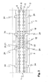
- FIG. 1 shows a longitudinal section through a fixed lane 1 in the region of a shock 12 of two bridge beams 2.
- the solid track is formed in the present embodiment of concrete slabs 3, which are firmly connected to their joints 4 and thus form a continuous band.
- the connection of the individual concrete slabs 3 in the joints 4 can be done conventionally by a compound of a clamping reinforcement and potting the joints in the joints 4 with concrete.
- rails 6 6 are laid on rail supports.
- the concrete slabs 3 are arranged on a profiled concrete layer 7. This can be done, for example, by adjusting the concrete slabs 3 by means of spindles on the profiled concrete layer 7 and then fixing them with a sub-casting between the concrete slab 3 and the profiled concrete layer 7.
- the concrete layer 7 thus forms for the concrete slabs 3 a solid and consistent in their location surface for permanent laying of the fixed lane. 1
- a sliding layer 10 is arranged between the profiled concrete layer 7 and the top of the bridge girder 2, a sliding layer 10 is arranged.
- the solid lane 1 and the profiled concrete layer 7 can slide on the bridge girder 2.
- unacceptable tension is avoided and it arises, especially in the area of the fixed lane 1, very consistent structure, which significantly increases the ride comfort of SchienendGermanes and on the other hand is relatively inexpensive to manufacture.
- the joints 4 of the fixed carriageway 1 no longer need to correspond to the bumps 12 of the bridge girders in this building as before.
- the solid lane 1 runs over the joints 12 of the bridge girder 2 without interruption.
- the production of the individual concrete slabs 3 can therefore be done in a conventional standardized manner. It is not necessary to take into account the respective lengths of the individual bridge girders 2. In particular, in the case of routes which are characterized by a large number of bridges, this construction method is of particularly great advantage over the prior art since, in a conventional design, a multiplicity of special lengths of the concrete slabs 3 would be required.
- the bridge girders 2 are arranged on a pillar 14 in the section shown here. They are each on a fixed bearing 15 and a Floating bearing 16 supported. As a result, the longitudinal extent of the bridge girder 2, starting from the fixed bearing 15, takes place in the direction of the floating bearing 16 of the same bridge girder 2. The gap in the joint 12 is thereby smaller or larger depending on the longitudinal extent of the bridge girder 2.
- armature 18 are arranged in the region of the fixed bearing 15 of the bridge girder 2, which connect the profiled concrete layer 7 with the concrete beam 2. Thermal expansions of the units profiled concrete layer 7 and concrete slabs 3 and bridge girder 2 are thus rectified in their direction, so that a lower relative movement of the two units is to be expected.
- the anchors 18 are advantageously screw-in. This means that 2 Einschraubhülsen are concreted into the top of the bridge girder, in which the anchor 18 are screwed in just before concreting the profiled concrete layer 7. This has the advantage that the top of the bridge girder 2 can be used during the manufacture of the structure as a guideway for construction vehicles, without the anchor 18, which would otherwise protrude from the top of the bridge girder 2, damaged.
- a hard foam layer 20 is arranged in the region of the joint 12 on the bridge girders 2 and under the profiled concrete layer 7.
- An optionally occurring kink between two bridge girders 2 in the region of the joint 12 thus does not press against the profiled concrete layer 7, but moves into the hard foam layer 20 and compresses it Hard foam without exerting on the profiled concrete layer 7 an impermissible compressive force.
- the hard foam layer 20 may consist of rigid foam plates, which are inserted into a recess provided for this purpose of the bridge carrier. A thickness of hard foam layer 20 of a few centimeters is usually sufficient. Likewise, an overlap of the joint 12 to a length of 1-2 m is also sufficient to compensate for the expected relative movements of profiled concrete layer 7 and bridge girder 2 in the vertical direction. Although the depression in the upper side of the bridge girder 2 for receiving the hard foam layer 20 is advantageous for the production, since the position of the hard foam layer 20 is reliably retained when concreting the profiled concrete layer 7, it is not necessarily required for the function.
- a support plate 21 is arranged on the hard foam layer 20.
- the support plate 21 ensures that the reinforcement does not sink to the hard foam layer 20 during concreting, but maintains a predetermined distance thereto.
- the reinforcement can accordingly be supported on the support plate 21, for example with feet arranged thereon.
- dowels 22 are provided. They are introduced after the laying of the fixed lane 1 in the fixed lane 1 and the profiled concrete layer 7 and provide additional security for the connection of the fixed lane 1 with the profiled concrete layer 7, in particular in the region of the shock 12th
- FIG. 2 shows a plan view of a fixed lane 1 on bridge girders 2 in the region of the joint 12 of two bridge girder 2. It is apparent from that the solid track 1 as well as the profiled concrete layer 7 forms a continuous band which passes over the joint 12 of two bridge girders 2. In the region of the joint 12, the hard foam layer 20 and the support plate 21 are incorporated. Likewise, in this area, the armature 18 and the dowels 22 are provided to provide a compound of the profiled concrete layer 7 with the bridge girder 2 and with the fixed carriageway 1.
- the rails 6 of the track for the rail-guided vehicle are laid on a plurality of rail supports 5. Depending on the system of rail installation but this can also be done differently.
- the fixed track 1 is not made of precast concrete slabs or a plate grate, but of individual sleepers, which carry both rails 6 and are connected to each other with concrete and reinforcement. It is essential in any case that a continuous band of the fixed track 1 is formed, which is formed independently of the impact 12 consecutively.
- stoppers 24 are provided.
- the stoppers 24 are mounted on the bridge girder 2 and guide the fixed carriageway 1 and the profiled concrete layer 7 in the transverse direction.
- the contact point to the fixed lane 1 and profiled concrete layer 7 is loose, so that in a longitudinal expansion tensions are avoided. It may therefore be advantageous to provide a sliding layer between the stopper 24 and the fixed track 1 and the profiled concrete layer 7 here as well. Due to the fixed connection between the fixed track 1 and the profiled concrete layer 7, it may also be sufficient to arrange the stopper 24 only with respect to the profiled concrete layer 7 and to guide it laterally.
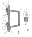
- FIG. 3 shows a cross section through the building according to the invention.
- a section through the bridge girder 2 and the fixed carriageway 1 in the region of a joint 12 of two bridge girders 2 is shown on the left side of the illustration. It is therefore the hard foam layer 20 and the support plate 21 can be seen under the profile concrete layer 7.
- the profiled concrete layer 7 is wedge-shaped, so that the solid lane 1 is excessive. This is necessary in particular in curved sections of the track of the fixed track 1.
- standard components of the fixed track 1 are also used in these areas.
- the elevation is carried out with the aid of the profiled concrete layer 7, which is concreted as needed.
- stopper 24 are arranged laterally.
- the stoppers 24 are on the one hand firmly connected to the bridge girder 2 and on the other hand, the profiled concrete layer 7 and the fixed carriageway 1 can slide along the stopper 24.
- FIG. 3 The right half of the representation of FIG. 3 shows a cross section in the region of the normal distance, away from the joint 12. Between the bridge girder 2 and the profiled concrete layer 7, the sliding layer 10 is arranged, which allows sliding of the profiled concrete layer 7 on the bridge girder 2. Incidentally, this representation corresponds to the representation on the left side of FIG. 3 ,
- FIG. 4 shows a detail of the sliding connection between profiled concrete layer 7 and bridge girder 2.
- a geotextile 26 is arranged on top of the Bridge support 2 as well as on the underside of the profiled concrete layer 7 .
- the geotextiles 26 are similar to the irregularities of the surfaces of the bridge girder 2 and the profile concrete layer 7. Partly they soak in concreting with the concrete when they are applied before setting the concrete. Usually, the geotextile 26 will be applied to the bridge girder 2, however, only after the setting of the concrete.
- the profiled concrete layer 7 is usually concreted onto the geotextile 26, penetrates into the geotextile 26 during concreting and thus creates a firm connection.
- the two films 27 provide a sliding movement of the profiled concrete layer 7 on the bridge girder 2, which has a very low friction.
- the two films 27 slide against each other without much resistance.
Landscapes
- Engineering & Computer Science (AREA)
- Architecture (AREA)
- Civil Engineering (AREA)
- Structural Engineering (AREA)
- Bridges Or Land Bridges (AREA)
- Road Paving Structures (AREA)
Description
- Die vorliegende Erfindung betrifft eine feste Fahrbahn auf einem Brückenbauwerk, bei welcher zum Lagern einer Schiene für ein schienengeführtes Fahrzeug eine Betonplatte auf einem Brückenträger angeordnet ist .
- Eine Fahrbahn dieser Act ist aus der
DE 30 / Z 867 A1 - Feste Fahrbahnen werden üblicherweise für Hochgeschwindigkeitsstrecken im Eisenbahnverkehr eingesetzt. Hierbei wird ein Betonband gebildet, welches entweder aus miteinander verbundenen Betonfertigteilplatten oder aus einzelnen Schwellen, welche mit Ortbeton verbunden werden, besteht. Die feste Fahrbahn ist dabei auf einer hydraulisch gebundenen Tragschicht justiert und befestigt. Sie bildet ein nahezu endloses durchgehendes Betonband, auf welchem die Schienen für das Gleis verlegt werden. Im Bereich von Brücken wird dieses Band allerdings unterbrochen, um Relativbewegungen der Brückenträger in Bezug auf die Betonplatten der festen Fahrbahn zu vermeiden. Es werden in diesem Falle die Betonplatten entsprechend der Länge der Brückenträger verlegt. An der Schnittstelle zweier Brückenträger wird auch dieses Betonband unterbrochen, so dass die Dehnungen des Brückenträgers direkt auf die Betonplatten der festen Fahrbahn übertragen werden können und dabei unzulässige Verspannungen des Verbundsystems Brückenträger-Betonplatte vermieden werden. Nachteilig bei dieser Art der Verlegung der festen Fahrbahn auf einem Brückenbauwerk ist, dass die Betonplatten in ihrer Länge mit der Länge des Brückenträgers übereinstimmen müssen. Es ist daher insbesondere bei der Verwendung von Betonfertigteilplatten erforderlich, dass Sonderlängen der Betonfertigteilplatten gefertigt werden, um sie der Länge des Brückenträgers anpassen zu können. Darüber hinaus ist es nachteilig, dass in der festen Fahrbahn ebenso wie an den Brückenträgern Dehnungsfugen vorgesehen sind, welche eine aufwendige Schienenkonstruktion erforderlich machen können.
- Aufgabe der vorliegenden Erfindung ist es daher, eine feste Fahrbahn auf einem Brückenbauwerk zu schaffen welche unabhängig von der Länge der einzelnen Brückenträger ist und darüber hinaus kostengünstig herstellbar ist.
- Die vorliegende Erfindung wird gelöst mit einer festen Fahrbahn auf einem Brückenbauwerk mit den Merkmalen des Anspruchs 1.
- Erfindungsgemäß bildet die Betonplatte der festen Fahrbahn ein über mindestens zwei Brückenträger durchgehend verlaufendes Band. Die Dehnungsfuge zwischen den beiden Brückenträgern bleibt somit unberücksichtigt für den Verlauf des Betonbandes. Nachdem aufgrund der hohen Masse des Brückenträgers im Vergleich zur Betonplatte und aufgrund der Richtung der Wärmeeinstrahlung die Betonplatte sehr viel höheren Wärmedehnungen ausgesetzt ist als der Brückenträger selbst, und der Brückenträger in seiner Wärmeausdehnung wesentlich träger als die Betonplatte ist, wurde ein erfindungsgemäßer Aufbau geschaffen, welcher die Brückenträger unabhängig von dem Betonplattenband macht. Dieser Aufbau beinhaltet eine Profilbetonschicht zwischen der Betonplatte und dem Brückenträger. Die Profilbetonschicht ist ebenso wie das Betonplattenband durchgehend ausgebildet. Zwischen der Profilbetonschicht und dem Brückenträger ist eine Gleitschicht angeordnet, während die Profilbetonschicht mit der Betonplatte der festen Fahrbahn fest verbunden ist. Auf diese Weise ist es der Betonplatte und der Profilbetonschicht ermöglicht, auf dem Brückenträger zu gleiten. Die Wärmedehnungen können somit weitgehend unabhängig voneinander stattfinden. Die Profilbetonschicht übernimmt die Funktion der herkömmlichen hydraulisch gebundenen Tragschicht, auf welcher die Betonplatte aufgebaut wird. Während jedoch die hydraulisch gebundene Tragschicht fest mit dem Untergrund verbunden ist, ist die Profilbetonschicht auf den Brückenträgern gleitend angeordnet und überbrückt die Dehnungsfugen der einzelnen Brückenträger. Es wird somit eine feste Fahrbahn geschaffen, welche auch im Bereich von Brücken ohne Unterbrechung durchgehend gebaut werden kann. Ein Schienenausgleich zur Überbrückung von Fugen ist nicht mehr erforderlich. Hierdurch wird die feste Fahrbahn kostengünstig herstellbar und zudem im Fahrbetrieb noch komfortabler als bisher.
- In einer bevorzugten Ausbildung der erfindungsgemäßen festen Fahrbahn ist der Brückenträger auf einem Festlager und einem Loslager abgestützt und die Profilbetonschicht im Bereich des Festlagers des Brückenträgers fest mit diesem verbunden. Hierdurch werden in vorteilhafter Weise die unterschiedlichen Ausdehnungen von fester Fahrbahn und Profilbetonschicht in Bezug auf den Brückenträger dahingehend beeinflusst, dass die Ausdehnungen grundsätzlich im wesentlichen in der selben Richtung erfolgen. Die Relativbewegungen der beiden Einheiten zueinander bleiben damit relativ gering.
- Besonders vorteilhaft wird die feste Verbindung von Brückenträger und Profilbetonschicht mit Verbindungselementen wie Anker, insbesondere Einschraubanker, Bügelbewehrung oder Dübel geschaffen, welche beispielsweise aus dem Brückenträger herausragen und auf welche die Profilbetonschicht betoniert wird. Besonders vorteilhaft ist es dabei, wenn die Anker Einschraubanker sind und damit erst unmittelbar vor dem Betonieren der Profilbetonschicht in den Brückenträger eingeschraubt werden. Es ist damit möglich, dass der Brückenträger bevor die Profilbetonschicht betoniert wird mit Baufahrzeugen befahren werden kann, ohne dass die Anker beschädigt werden.
- Einen besonderen Vorteil bringt die Verwendung einer nachgiebigen Schicht, beispielsweise einer Hartschaumschicht oder einer Elastomerschicht im Bereich von Stößen zweier Brückenträger, welche zwischen den Brückenträgern und der Profilbetonschicht angeordnet ist. Nachdem die einzelnen Brückenträger unabhängig voneinander sind und im Gegensatz dazu die Profilbetonschicht und die Betonplatte als ein durchgehendes Band auch über die Dehnungsfugen der Brückenträger hinaus verläuft, entstehen unterschiedliche Biegelinien der beiden Einheiten. Die Brückenträger werden sich jeweils bogenförmig durchbiegen, während Betonplatte und Profilbetonschicht wellenförmig über die einzelnen Brückenträger verlaufen. Um hier zu große Spannungen im Bereich zwischen zwei Brückenträgern zu vermeiden, ist die Hartschaumschicht vorgesehen. Die Enden der Brückenträger können sich im Extremfall in die nachgiebige Schicht hinein- und herausbewegen, ohne eine unzulässige Druckkraft auf die Profilbetonschicht und Betonplatte auszuüben. Die Belastung auf das durchgehende Band wird hierdurch reduziert. Die nachgiebige Schicht bildet somit ein besonders vorteilhaftes Element bei der vorliegenden Bauausführung. Die nachgiebige Schicht kann beispielsweise eine Hartschaumschicht sein, welche in Form von Hartschaumplatten auf die Brückenträger vor dem Betonieren der Profilbetonschicht aufgelegt wird. Es wird damit gleichzeitig eine Schalung für die Profilbetonschicht im Bereich der voneinander beabstandeten Stöße zweier benachbarter Brückenträger erhalten.
- Ist auf der nachgiebigen Schicht zur Profilbetonschicht hin eine Stützplatte angeordnet, so kann auf dieser Stützplatte vorteilhafterweise die Bewehrung für die Profilbetonschicht vor und während des Betonierens abgelegt werden ohne die nachgiebige Schicht zu beschädigen oder undefiniert in der Profilbetonschicht einbetoniert zu werden.
- Ist in dem Brückenträger eine Vertiefung angeordnet zur teilweisen Aufnahme der nachgiebigen Schicht, so wird einerseits die Lage der Hartschaumschicht auf dem Brückenträger definiert und andererseits wird die Profilbetonschicht im Bereich der nachgiebigen Schicht nicht sonderlich geschwächt. Die Bauhöhe der Profilbetonschicht ist somit im Bereich des Übergangs zweier Brückenträger nahezu gleich der Dicke im übrigen Verlauf der Profilbetonschicht.
- Obwohl die Betonplatte der festen Fahrbahn mit der Profilbetonschicht weitgehend fest, üblicherweise mittels Kraftschuss, verbunden ist, so wird eine besonders hohe Stabilität erreicht, wenn im Bereich von Stößen zweier Brückenträger die Betonplatte der festen Fahrbahn mit der Profilbetonschicht formschlüssig verbunden ist. Diese formschlüssige Verbindung kann besonders einfach durch eine Verschraubung der Betonplatte mit der Profilbetonschicht erfolgen. Es sind hierfür aber auch Einschraubanker, Bügelbewehrungen oder nachträglich gebohrte und vergossene Dübel möglich.
- Die Gleitschicht zwischen Profilbetonschicht und Brückenträger wird vorteilhafterweise aus einer Folie und/oder einem Geotextil hergestellt. Auch die Verwendung von zwei Folien, welche aufeinanderliegen und damit definiert aneinander gleiten können, ist vorteilhaft. Das Geotextil hat den Vorteil, dass es von dem Beton zumindest teilweise getränkt wird und sich damit sehr gut mit dem Beton verbindet. Unebenheiten des Brückenträgers können mit dem Geotextil, welches eine Dicke von 2-10 mm aufweisen kann, ausgeglichen werden. Das Gleiten der Profilbetonschicht auf dem Brückenträger wird hierdurch wesentlich erleichtert. Verspannungen können damit weitgehend vermieden werden. Eine Geotextilschicht kann hierzu auf dem Brückenträger und/oder auf der dem Brückenträger zugewandten Seite der Profilbetonschicht angeordnet sein und dazwischen eine oder zwei Folien, beispielsweise PE-Folien mit einer Stärke von etwa 0,3 - 0,5 mm aufweisen.
- Besonders vorteilhaft für die Erfindung ist es, wenn die Betonplatte aus einzelnen Betonfertigteilplatten besteht, welche miteinander zu einem durchgehenden Band verbunden sind. Dies kann beispielsweise in herkömmlicher Weise geschehen, wie es von dem System "Feste Fahrbahn - Bögl" bekannt ist. Alternativ ist die Erfindung natürlich auch einsetzbar für eine feste Fahrbahn, welche aus ungekoppelten Fertigteilplatten oder aus in Ortbeton eingegossenen Schwellen besteht.
- Die Betonfertigteilplatten können in besonders vorteilhafter Ausführung Standardteile mit üblicher Länge sein, die ohne Berücksichtigung der Stöße der Brückenträger verlegt sind. Nachdem die Betonfertigteilplatten auf der Profilbetonschicht verlegt sind, welche ein durchgehendes Band bildet, muss auf die Stöße der Brückenträger bei der Verlegung der Betonfertigteilplatten keine Rücksicht genommen werden. Das durchgehende Band der Profilbetonschicht gleitet auf den Brückenträgern zusammen mit dem Band aus Betonfertigteilplatten der festen Fahrbahn.
- Die Profilbetonschicht weist neben den oben genannten Vorteilen weiterhin den Vorteil auf, dass die Streckenführung der festen Fahrbahn mit der Profilbetonschicht ausgeführt werden kann. Insbesondere eine Überhöhung der Streckenführung, beispielsweise in Kurvenabschnitten, wird mit Hilfe der Profilbetonschicht geformt. Die Betonplatten, insbesondere die Betonfertigteilplatten, können dabei in stets gleicher Ausführung verlegt werden. Sondermaße der Betonfertigteilplatten sind in den meisten Fällen nicht erforderlich.
- Um eine stabile Profilbetonschicht zu erhalten, welche Druck- und Zugspannungen aus Wärmedehnungen, aber auch aus Beschleunigungskräften der Schienenfahrzeuge aufnehmen kann, ist die Profilbetonschicht bewehrt ausgeführt.
- Insbesondere um ein seitliches Ausbrechen der Profilbetonschicht und der festen Fahrbahn zu vermeiden, sind an dem Brückenträger Stopper zur seitlichen Führung der Profilbetonschicht und/oder der Betonplatte der festen Fahrbahn angeordnet. Die Stopper erlauben eine Relativbewegung der Profilbetonschicht und/oder der Betonplatte in Längsrichtung der Schienen. Eine seitliche Bewegung der Profilbetonschicht und/oder der Betonplatte auf den Brückenträgern wird durch die Stopper, welche beiderseits der Profilbetonschicht und/oder der Betonplatte angeordnet sind, vermieden.
- Weitere Vorteile der Erfindung sind in den nachfolgenden Ausführungsbeispielen beschrieben. Es zeigt:
- Figur 1
- einen Längsschnitt durch eine feste Fahrbahn auf einem Brückenbauwerk im Bereich eines Stoßes zweier Brückenträger;
- Figur 2
- eine Draufsicht auf eine feste Fahrbahn in einem Bereich wie in
Figur 1 ; - Figur 3
- einen Querschnitt durch einen Brückenträger und
- Figur 4
- einen Ausschnitt mit einer Detailansicht der Gleitschicht.
-
Figur 1 zeigt eine Längsschnitt durch eine feste Fahrbahn 1 im Bereich eines Stoßes 12 zweier Brückenträger 2. Die feste Fahrbahn ist in dem vorliegenden Ausführungsbeispiel aus Betonplatten 3 gebildet, welche an ihren Stößen 4 fest miteinander verbunden sind und damit ein durchgehendes Band bilden. Die Verbindung des einzelnen Betonplatten 3 in den Stößen 4 können herkömmlicherweise durch eine Verbindung einer Spannbewehrung und Verguss der Fugen in den Stößen 4 mit Beton erfolgen. Auf der festen Fahrbahn 1 sind auf Schienenstützpunkten 5 Schienen 6 verlegt. - Die Betonplatten 3 sind auf einer Profilbetonschicht 7 angeordnet. Dies kann beispielsweise dadurch geschehen, dass die Betonplatten 3 mittels Spindeln auf der Profilbetonschicht 7 justiert werden und anschließend mit einem Unterguss zwischen der Betonplatte 3 und der Profilbetonschicht 7 fixiert werden. Die Profilbetonschicht 7 bildet somit für die Betonplatten 3 einen festen und in ihrer Lage gleichbleibenden Untergrund zur dauerhaften Verlegung der festen Fahrbahn 1.
- Zwischen der Profilbetonschicht 7 und der Oberseite des Brückenträgers 2 ist eine Gleitschicht 10 angeordnet. Um unterschiedliche Ausdehnungen, welche insbesondere durch Sonneneinstrahlung und die unterschiedlichen Massen des Brückenträgers 2 und der festen Fahrbahn 1 mit der Profilbetonschicht 7 eintreten, ist es besonders vorteilhaft, wenn die feste Fahrbahn 1 und die Profilbetonschicht 7 auf dem Brückenträger 2 gleiten können. Es werden hierdurch unzulässige Verspannungen vermieden und es entsteht ein, insbesondere im Bereich der festen Fahrbahn 1, sehr gleichbleibendes Bauwerk, welches den Fahrkomfort des Schienendfahrzeuges deutlich erhöht und andererseits relativ kostengünstig in der Herstellung ist. Die Stöße 4 der festen Fahrbahn 1 müssen bei diesem Bauwerk nicht mehr wie bisher mit den Stößen 12 der Brückenträger korrespondieren. Die feste Fahrbahn 1 läuft über die Stöße 12 der Brückenträger 2 ohne Unterbrechung hinweg. Die Fertigung der einzelnen Betonplatten 3 kann daher in herkömmlicher standardisierter Weise erfolgen. Es muss nicht auf die jeweiligen Längen der einzelnen Brückenträger 2 Rücksicht genommen werden. Insbesondere bei Strecken, welche durch eine Vielzahl von Brücken gekennzeichnet sind, ist diese Bauweise von besonders großem Vorteil gegenüber dem Stand der Technik, da bei einer herkömmlichen Bauweise eine Vielzahl von Sonderlängen der Betonplatten 3 benötigt werden würden.
- Die Brückenträger 2 sind bei dem hier dargestellten Ausschnitt auf einem Pfeiler 14 angeordnet. Sie sind jeweils auf einem Festlager 15 und einem Loslager 16 abgestützt. Hierdurch wird die Längsausdehnung des Brückenträgers 2 von dem Festlager 15 ausgehend in Richtung auf das Loslager 16 des selben Brückenträgers 2 erfolgen. Der Spalt in dem Stoß 12 wird hierdurch je nach Längenausdehnung des Brückenträgers 2 kleiner oder größer.
Um Schubkräfte aus der festen Fahrbahn 1 und der Profilbetonschicht 7 auf den Brückenträger 2 übertragen zu können, sind Anker 18 im Bereich des Festlagers 15 des Brückenträgers 2 angeordnet, welche die Profilbetonschicht 7 mit dem Betonträger 2 verbinden. Wärmeausdehnungen der Einheiten Profilbetonschicht 7 und Betonplatten 3 sowie Brückenträger 2 werden hierdurch auch in ihrer Richtung gleichgerichtet, so dass eine geringere Relativbewegung der beiden Einheiten zu erwarten ist. - Die Anker 18 sind vorteilhafterweise Einschraubanker. Dies bedeutet, dass an der Oberseite der Brückenträger 2 Einschraubhülsen einbetoniert sind, in welche die Anker 18 erst kurz vor dem Betonieren der Profilbetonschicht 7 eingeschraubt werden. Dies hat den Vorteil, dass die Oberseite der Brückenträger 2 während der Herstellung des Bauwerkes als Fahrweg für Baufahrzeuge genutzt werden kann, ohne dass die Anker 18, welche ansonsten aus der Oberseite des Brückenträgers 2 herausragen würden, beschädigt werden.
- Nachdem die Brückenträger 2 nicht miteinander verbunden sind, werden sie sich bei einer Belastung jeweils bogenförmig durchbiegen. Im Gegensatz hierzu wird die Bewegung des durchgehenden Bandes der Profilbetonschicht 7 und der festen Fahrbahn 1 eher wellenförmig erfolgen. Um einen unzulässigen Knick des durchgehenden Bandes im Bereich des Stoßes 12 zu vermeiden, ist eine Hartschaumschicht 20 im Bereich des Stoßes 12 auf den Brückenträgern 2 und unter der Profilbetonschicht 7 angeordnet. Ein gegebenenfalls auftretender Knick zwischen zwei Brückenträgern 2 im Bereich des Stoßes 12 drückt somit nicht gegen die Profilbetonschicht 7, sondern bewegt sich in die Hartschaumschicht 20 hinein und komprimiert den Hartschaum ohne auf die Profilbetonschicht 7 eine unzulässige Druckkraft auszuüben. Die Hartschaumschicht 20 kann aus Hartschaumplatten bestehen, welche in eine dafür vorgesehene Vertiefung des Brückenträgers eingelegt sind. Eine Dicke der Hartschaumschicht 20 von wenigen Zentimetern ist üblicherweise ausreichend. Ebenso ist eine Überlappung des Stoßes 12 auf einer Länge von 1-2 m ebenfalls ausreichend, um die zu erwartenden Relativbewegungen von Profilbetonschicht 7 und Brückenträger 2 in vertikaler Richtung ausgleichen zu können. Die Vertiefung in der Oberseite des Brückenträgers 2 zur Aufnahme der Hartschaumschicht 20 ist zwar vorteilhaft für die Herstellung, da die Position der Hartschaumschicht 20 beim Betonieren der Profilbetonschicht 7 sicher beibehalten wird, sie ist aber für die Funktion nicht notwendigerweise erforderlich.
- Um beim Betonieren der Profilbetonschicht 7 die Position der darin befindlichen Bewehrung sicherstellen zu können, ist es vorteilhaft, wenn auf der Hartschaumschicht 20 eine Stützplatte 21 angeordnet ist. Die Stützplatte 21 stellt sicher, dass die Bewehrung nicht auf die Hartschaumschicht 20 beim Betonieren sinkt, sondern einen vorbestimmten Abstand hierzu einhält. Die Bewehrung kann sich dementsprechend auf der Stützplatte 21, beispielsweise mit daran angeordneten Füssen, abstützen.
- Um eine feste Verbindung zwischen den Betonplatten 3 der festen Fahrbahn 1 und der Profilbetonschicht 7 im Bereich des Stoßes 12 sicherzustellen, sind Dübel 22 vorgesehen. Sie werden nach der Verlegung der festen Fahrbahn 1 in die feste Fahrbahn 1 und die Profilbetonschicht 7 eingebracht und sorgen für eine zusätzliche Sicherheit für die Verbindung der festen Fahrbahn 1 mit der Profilbetonschicht 7, insbesondere im Bereich des Stoßes 12.
-
Figur 2 zeigt eine Draufsicht auf eine feste Fahrbahn 1 auf Brückenträgern 2 im Bereich des Stoßes 12 zweier Brückenträger 2. Es ist daraus ersichtlich, dass die feste Fahrbahn 1 ebenso wie die Profilbetonschicht 7 ein durchgehendes Band bildet, welches über den Stoß 12 zweier Brückenträger 2 hinwegläuft. Im Bereich des Stoßes 12 sind die Hartschaumschicht 20 und die Stützplatte 21 eingearbeitet. Ebenso sind in diesem Bereich die Anker 18 und die Dübel 22 vorgesehen, um eine Verbindung der Profilbetonschicht 7 mit dem Brückenträger 2 bzw. mit der festen Fahrbahn 1 zu schaffen. Die Schienen 6 des Gleises für das schienengeführte Fahrzeug sind auf einer Vielzahl von Schienenstützpunkten 5 verlegt. Je nach System der Schienenverlegung kann dies aber auch anders ausgeführt sein. So kann anstelle der diskontinuierlichen Schienenabstützung auch eine kontinuierliche Abstützung erfolgen. Auch ist es möglich, dass die feste Fahrbahn 1 nicht aus Betonfertigteilplatten oder einem Plattenrost hergestellt ist, sondern aus einzelnen Schwellen, welche beide Schienen 6 tragen und untereinander mit Beton und Bewehrung verbunden sind. Wesentlich ist jedenfalls, dass ein durchgehendes Band der festen Fahrbahn 1 entsteht, welches unabhängig von dem Stoß 12 fortlaufend ausgebildet ist. - Zur Sicherstellung einer gleichbleibenden Position der festen Fahrbahn 1 in Bezug auf die Querausrichtung zum Brückenträger 2 sind Stopper 24 vorgesehen. Die Stopper 24 sind auf dem Brückenträger 2 befestigt und führen die feste Fahrbahn 1 sowie die Profilbetonschicht 7 in Querrichtung. Die Kontaktstelle zur festen Fahrbahn 1 und Profilbetonschicht 7 ist lose, so dass bei einer Längenausdehnung Verspannungen vermieden werden. Es kann deshalb vorteilhaft sein, auch hier eine Gleitschicht zwischen dem Stopper 24 und der festen Fahrbahn 1 und der Profilbetonschicht 7 vorzusehen. Aufgrund der festen Verbindung zwischen der festen Fahrbahn 1 und der Profilbetonschicht 7 kann es auch ausreichend sein, den Stopper 24 lediglich in Bezug auf die Profilbetonschicht 7 anzuordnen und diese seitlich zu führen.
-
Figur 3 zeigt einen Querschnitt durch das erfindungsgemäße Bauwerk. Dabei ist auf der linken Seite der Darstellung ein Schnitt durch den Brückenträger 2 und die feste Fahrbahn 1 im Bereich eines Stoßes 12 zweier Brückenträger 2 dargestellt. Es ist deshalb die Hartschaumschicht 20 und die Stützplatte 21 unter der Profilbetonschicht 7 zu sehen. Die Profilbetonschicht 7 ist keilförmig ausgebildet, so dass die feste Fahrbahn 1 überhöht ist. Dies ist insbesondere in Kurvenabschnitten der Strecke der festen Fahrbahn 1 erforderlich. Wie aus der Darstellung ersichtlich ist, sind auch in diesen Bereichen Standardbauteile der festen Fahrbahn 1 verwendbar. Die Überhöhung wird mit Hilfe der Profilbetonschicht 7 ausgeführt, welche je nach Bedarf betoniert wird. Zur seitlichen Führung der festen Fahrbahn 1 und der Profilbetonschicht 7 sind Stopper 24 seitlich angeordnet. Die Stopper 24 sind einerseits mit dem Brückenträger 2 fest verbunden und andererseits können die Profilbetonschicht 7 und die feste Fahrbahn 1 entlang der Stopper 24 gleiten. - Die rechte Hälfte der Darstellung der
Figur 3 zeigt einen Querschnitt im Bereich der normalen Strecke, abseits des Stoßes 12. Zwischen dem Brückenträger 2 und der Profilbetonschicht 7 ist die Gleitschicht 10 angeordnet, welche ein Gleiten der Profilbetonschicht 7 auf dem Brückenträger 2 erlaubt. Im Übrigen entspricht diese Darstellung der Darstellung auf der linke Seite derFigur 3 . -
Figur 4 zeigt ein Detail der gleitenden Verbindung zwischen Profilbetonschicht 7 und Brückenträger 2. Um ein Gleiten der relativ rauhen Oberflächen des Brückenträgers 2 und der Profilbetonschicht 7 aneinander zu erlauben, ohne dass ein großer Widerstand dabei entsteht, ist bei dieser Ausführung vorgesehen, dass auf der Oberseite des Brückenträgers 2 ebenso wie auf der Unterseite der Profilbetonschicht 7 jeweils ein Geotextil 26 angeordnet ist. Zwischen den Geotextilien 26 befinden sich zwei Folien 27. Die Geotextilien 26 gleichen die Ungleichmäßigkeiten der Oberflächen des Brückenträgers 2 und der Profilbetonschicht 7 aus. Sie tränken sich teilweise beim Betonieren mit dem jeweiligen Beton, wenn sie vor dem Abbinden des Betons aufgebracht werden. Üblicherweise wird das Geotextil 26 auf dem Brückenträger 2 allerdings erst nach dem Abbinden des Betons aufgebracht werden. Eine Durchtränkung des Geotextiles 26 erfolgt in diesem Falle nicht. Hingegen wird die Profilbetonschicht 7 üblicherweise auf die Geotextil 26 aufbetoniert, dringt beim Betonieren in das Geotextil 26 ein und schafft somit eine feste Verbindung. Die beiden Folien 27 sorgen für eine Gleitbewegung der Profilbetonschicht 7 auf dem Brückenträger 2, welche eine sehr geringe Reibung aufweist. Die beiden Folien 27 gleiten aneinander ohne großen Widerstand. In einer einfacheren Ausführung der Erfindung ist es auch ausreichend, nur eine Folie 27 und gegebenenfalls sogar auch nur ein Geotextil 26 zu verwenden, um die Ungleichmäßigkeiten von Brückenträger 2 und Profilbetonschicht 7 auszugleichen und eine ausreichende Gleitwirkung zu erlauben. - Abwandlungen in der Gestaltung des Profilbetonschicht 7, dem Brückenträger 2 sowie der Gleitschicht 10 sind jederzeit im Rahmen der Patentansprüche möglich.
Claims (13)
- Feste Fahrbahn auf einem Brückenbauwerk, bei welcher zum Lagern einer Schiene (6) für ein schienengeführtes Fahrzeug eine Betonplatte (3) auf einem Brückenträger (2) angeordnet ist, dadurch gekennzeichnet, dass die Betonplatte (3) ein über mindestens zwei Brückenträger (2) durchgehend verlaufendes Band bildet, zwischen der Betonplatte (3) und dem Brückenträger (2) eine durchgehende Profilbetonschicht (7) angeordnet ist, dass zwischen der Profilbetonschicht (7) und dem Brückenträger (2) eine Gleitschicht (10) angeordnet ist und die Profilbetonschicht (7) mit der Betonplatte (3) der festen Fahrbahn (1) fest verbunden ist.
- Feste Fahrbahn nach Anspruch 1, dadurch gekennzeichnet, dass der Brückenträger (2) auf einem Festlager (15) und einem Loslager (16) abgestützt ist und die Profilbetonschicht (7) im Bereich des Festlagers (15) des Brückenträgers (2) fest mit diesem verbunden ist.
- Feste Fahrbahn nach einem der vorherigen Ansprüche, dadurch gekennzeichnet, dass die feste Verbindung von Brückenträger (2) und Profilbetonschicht (7) mit Verbindungselementen wie Anker (18), insbesondere Einschraubanker, Bügelbewehrung oder Dübel vorgesehen ist.
- Feste Fahrbahn nach einem der vorherigen Ansprüche, dadurch gekennzeichnet, dass im Bereich von Stößen (12) zweier Brückenträger (2) eine nachgiebige Schicht, beispielsweise eine Hartschaumschicht (20) oder eine Elastomerschicht zwischen dem Brückenträger (2) und der Profilbetonschicht (7) angeordnet ist.
- Feste Fahrbahn nach einem der vorherigen Ansprüche, dadurch gekennzeichnet, dass auf der nachgiebigen Schicht (20) eine Stützplatte (21) angeordnet ist.
- Feste Fahrbahn nach einem der vorherigen Ansprüche, dadurch gekennzeichnet, dass in dem Brückenträger (2) eine Vertiefung angeordnet ist zur teilweisen Aufnahme der nachgiebigen Schicht (20).
- Feste Fahrbahn nach einem der vorherigen Ansprüche, dadurch gekennzeichnet, dass im Bereich von Stößen (12) zweier Brückenträger (2) die Betonplatte (3) der festen Fahrbahn (1) mit der Profilbetonschicht (7) formschlüssig, beispielsweise mittels Einschraubanker, Bügelbewehrung oder nachträglich gebohrte und vergossene Dübel verbunden, insbesondere verschraubt ist.
- Feste Fahrbahn nach einem der vorherigen Ansprüche, dadurch gekennzeichnet, dass die Gleitschicht (10) aus einer Folie (27) und/oder einem Geotextil (26) besteht.
- Feste Fahrbahn nach einem der vorherigen Ansprüche, dadurch gekennzeichnet, dass die Betonplatte (3) aus einzelnen Betonfertigteilplatten besteht, welche insbesondere miteinander zu einem durchgehenden Band verbunden sind.
- Feste Fahrbahn nach einem der vorherigen Ansprüche, dadurch gekennzeichnet, dass die Betonfertigteilplatten Standardteile sind, die ohne Berücksichtigung der Stöße (12) der Brückenträger (2) verlegt sind.
- Feste Fahrbahn nach einem der vorherigen Ansprüche, dadurch gekennzeichnet, dass die Streckenführung der festen Fahrbahn (1), insbesondere eine Überhöhung der Streckenführung beispielsweise in Kurvenabschnitten, im wesentlichen mit der Profilbetonschicht (7) ausgeführt ist.
- Feste Fahrbahn nach einem der vorherigen Ansprüche, dadurch gekennzeichnet, dass die Profilbetonschicht (7) bewehrt ist.
- Feste Fahrbahn nach einem der vorherigen Ansprüche, dadurch gekennzeichnet, dass an dem Brückenträger (2) Stopper (24) zur seitlichen Führung der Profilbetonschicht (7) und/oder der Betonplatte (3) der festen Fahrbahn (1) angeordnet sind.
Applications Claiming Priority (2)
| Application Number | Priority Date | Filing Date | Title |
|---|---|---|---|
| DE102005032912A DE102005032912A1 (de) | 2005-07-12 | 2005-07-12 | Feste Fahrbahn auf einem Brückenbauwerk |
| PCT/EP2006/063498 WO2007006640A1 (de) | 2005-07-12 | 2006-06-23 | Feste fahrbahn auf einem brückenbauwerk |
Publications (2)
| Publication Number | Publication Date |
|---|---|
| EP1904682A1 EP1904682A1 (de) | 2008-04-02 |
| EP1904682B1 true EP1904682B1 (de) | 2009-08-12 |
Family
ID=36753963
Family Applications (1)
| Application Number | Title | Priority Date | Filing Date |
|---|---|---|---|
| EP06777442A Not-in-force EP1904682B1 (de) | 2005-07-12 | 2006-06-23 | Feste fahrbahn auf einem brückenbauwerk |
Country Status (7)
| Country | Link |
|---|---|
| EP (1) | EP1904682B1 (de) |
| KR (1) | KR101293285B1 (de) |
| CN (1) | CN101223317B (de) |
| AT (1) | ATE439472T1 (de) |
| DE (2) | DE102005032912A1 (de) |
| ES (1) | ES2331023T3 (de) |
| WO (1) | WO2007006640A1 (de) |
Families Citing this family (13)
| Publication number | Priority date | Publication date | Assignee | Title |
|---|---|---|---|---|
| DE102007003351A1 (de) | 2007-01-17 | 2008-07-24 | Max Bögl Bauunternehmung GmbH & Co. KG | Feste Fahrbahn mit einem Betonband |
| JP5135630B2 (ja) * | 2007-11-12 | 2013-02-06 | 株式会社Kelk | 測定用基板及び温度測定用基板 |
| DE202008006153U1 (de) * | 2008-05-05 | 2008-07-10 | Db Netz Ag | Feste Fahrbahn für schienengebundene Fahrzeuge auf einer Brücke |
| WO2011120187A1 (zh) * | 2010-03-29 | 2011-10-06 | 上海磁浮交通发展有限公司 | 磁浮轨道梁端构造结构 |
| CN101831847B (zh) * | 2010-04-28 | 2012-02-01 | 肇庆俊富纤网材料有限公司 | 一种无碴轨道的后浇带施工方法 |
| CN102182119A (zh) * | 2011-03-31 | 2011-09-14 | 中铁第四勘察设计院集团有限公司 | 一种铁路无砟轨道跨越线下结构缝结构 |
| EP2865808A1 (de) * | 2013-10-23 | 2015-04-29 | Siemens S.A.S. | Durchgehende Fahrbahn auf Viaduktbauwerk |
| CN104452584A (zh) * | 2014-11-26 | 2015-03-25 | 安徽省交通投资集团有限责任公司 | 一种钢桥面铺装结构 |
| CN105064208B (zh) * | 2015-08-06 | 2016-10-05 | 福州大学 | 一种由预制uhpc板与钢桥面板组合的桥面板结构及其施工方法 |
| CN108625228B (zh) * | 2018-05-11 | 2020-05-19 | 北京铁科特种工程技术有限公司 | 一种耐候沥青混凝土无砟轨道结构 |
| CN109082948B (zh) * | 2018-09-03 | 2020-05-12 | 东南大学 | 一种底座板伸缩缝下沥青混凝土层的防裂结构及实施方法 |
| CN109778712A (zh) * | 2019-03-22 | 2019-05-21 | 北京市市政工程设计研究总院有限公司 | 一种用于桥面连续处限制梁端转角位移的方法及预制梁体 |
| CN115874532B (zh) * | 2022-12-29 | 2025-09-05 | 腾达建设集团股份有限公司 | 简支梁桥桥面连续结构及施工方法 |
Family Cites Families (10)
| Publication number | Priority date | Publication date | Assignee | Title |
|---|---|---|---|---|
| DE2443770C2 (de) * | 1974-09-13 | 1985-08-08 | Ed. Züblin AG, 7000 Stuttgart | Eisenbahnbrücke mit durchgehend geschweißten Gleisen |
| DE2543243C2 (de) * | 1975-09-27 | 1985-04-25 | Dyckerhoff & Widmann AG, 8000 München | Brückentragwerk mit gleitend auf dem Überbau aufgelagerten und ohne Unterbrechung über diesen hinweggeführten Verkehrsweg |
| DE2628398C3 (de) * | 1976-06-24 | 1978-12-21 | Buehrer, Rudolf, Dipl.-Ing., 8130 Starnberg | Fugeneinlage für eine Gleitfuge zwischen großflächigen Betonbauteilen |
| DE3012867A1 (de) * | 1980-04-02 | 1981-10-08 | Ed. Züblin AG, 7000 Stuttgart | Eisenbahnbruecke mit schotterlosem gleisoberbau |
| DE3919833A1 (de) * | 1989-06-16 | 1990-12-20 | Zueblin Ag | Verfahren zum auswechseln eines gleitlagers unter einer festen fahrbahn auf bruecken |
| CN2181530Y (zh) * | 1994-01-10 | 1994-11-02 | 黄亮雄 | 桥梁三防伸缩装置 |
| DE29723848U1 (de) * | 1997-05-13 | 1999-05-20 | Ed. Züblin AG, 70567 Stuttgart | Feste Fahrbahn auf Eisenbahnbrücken |
| DE19719987A1 (de) * | 1997-05-13 | 1998-06-04 | Zueblin Ag | Feste Fahrbahn auf Eisenbahn-Brücken |
| DE10333616A1 (de) * | 2003-06-06 | 2004-11-11 | Sbp Gmbh | Brücke, insbesondere Bahnbrücke |
| KR100646208B1 (ko) | 2005-03-16 | 2006-11-23 | 김학수 | 소음 및 진동 저감형 플레이트거더교 구조 |
-
2005
- 2005-07-12 DE DE102005032912A patent/DE102005032912A1/de not_active Withdrawn
-
2006
- 2006-06-23 AT AT06777442T patent/ATE439472T1/de active
- 2006-06-23 EP EP06777442A patent/EP1904682B1/de not_active Not-in-force
- 2006-06-23 KR KR1020087003349A patent/KR101293285B1/ko not_active Expired - Fee Related
- 2006-06-23 ES ES06777442T patent/ES2331023T3/es active Active
- 2006-06-23 CN CN2006800254302A patent/CN101223317B/zh not_active Expired - Fee Related
- 2006-06-23 WO PCT/EP2006/063498 patent/WO2007006640A1/de not_active Ceased
- 2006-06-23 DE DE502006004528T patent/DE502006004528D1/de active Active
Also Published As
| Publication number | Publication date |
|---|---|
| WO2007006640A1 (de) | 2007-01-18 |
| CN101223317B (zh) | 2011-06-22 |
| KR20080030662A (ko) | 2008-04-04 |
| ATE439472T1 (de) | 2009-08-15 |
| CN101223317A (zh) | 2008-07-16 |
| ES2331023T3 (es) | 2009-12-18 |
| EP1904682A1 (de) | 2008-04-02 |
| DE502006004528D1 (de) | 2009-09-24 |
| KR101293285B1 (ko) | 2013-08-09 |
| DE102005032912A1 (de) | 2007-01-18 |
Similar Documents
| Publication | Publication Date | Title |
|---|---|---|
| EP2102415B1 (de) | Feste fahrbahn mit einem betonband | |
| EP1218596B1 (de) | Stahlbetonfertigteilplatte | |
| AT508847B1 (de) | Vorrichtung zur überbrückung einer dehnfuge | |
| EP1904682B1 (de) | Feste fahrbahn auf einem brückenbauwerk | |
| EP3673113B1 (de) | Verfahren zur herstellung einer integralen brücke und integrale brücke | |
| EP3303707B1 (de) | Verfahren zur herstellung einer fahrbahnplatte für eine brücke | |
| EP2143843A2 (de) | Stahl-Beton-Verbundtrog als Brückenüberbau und Verfahren zu seiner Herstellung | |
| WO2007087781A1 (de) | Feste fahrbahn für schienenfahrzeuge | |
| EP1204798A1 (de) | Mehrfeldträger | |
| EP1825059B1 (de) | Betonfahrbahn für schienenfahrzeuge | |
| EP2806067B1 (de) | Trogbrücke mit einer Fahrbahnplatte aus Grobblech und Verfahren zur Herstellung einer Trogbrücke | |
| DE102008007815A1 (de) | Stahlbetonverbundbrücke mit horizontaler Verbundfuge und Verfahren zu ihrer Herstellung | |
| WO2021203150A1 (de) | Verfahren zur herstellung einer fahrbahnplatte für eine brücke | |
| EP2029813B1 (de) | Verfahren zur herstellung einer segmentfertigteilbrücke und segmentfertigteilbrücke | |
| AT520614B1 (de) | Verfahren zur Herstellung einer Fahrbahnplatte mit untenliegenden Fertigteilplatten | |
| DE19831984C2 (de) | Bauteil mit externen Spanngliedern | |
| WO2008019671A1 (de) | Fahrbahn für magnetschwebebahnen | |
| DE19952803A1 (de) | Oberbau für schienengebundene Fahrzeuge des öffentlichen Nahverkehrs sowie Verfahren und Vorrichtung zu seiner Herstellung | |
| EP0826848B1 (de) | Vorrichtung zur konzentrierten Krafteinleitung in Beton | |
| DE2729250A1 (de) | Bruecke | |
| DE2657371A1 (de) | Verbindungsquertraeger fuer aus einfeldlaengstraegern hergestellte brueckentragwerke |
Legal Events
| Date | Code | Title | Description |
|---|---|---|---|
| PUAI | Public reference made under article 153(3) epc to a published international application that has entered the european phase |
Free format text: ORIGINAL CODE: 0009012 |
|
| 17P | Request for examination filed |
Effective date: 20071220 |
|
| AK | Designated contracting states |
Kind code of ref document: A1 Designated state(s): AT BE BG CH CY CZ DE DK EE ES FI FR GB GR HU IE IS IT LI LT LU LV MC NL PL PT RO SE SI SK TR |
|
| DAX | Request for extension of the european patent (deleted) | ||
| GRAP | Despatch of communication of intention to grant a patent |
Free format text: ORIGINAL CODE: EPIDOSNIGR1 |
|
| GRAS | Grant fee paid |
Free format text: ORIGINAL CODE: EPIDOSNIGR3 |
|
| DAX | Request for extension of the european patent (deleted) | ||
| GRAA | (expected) grant |
Free format text: ORIGINAL CODE: 0009210 |
|
| AK | Designated contracting states |
Kind code of ref document: B1 Designated state(s): AT BE BG CH CY CZ DE DK EE ES FI FR GB GR HU IE IS IT LI LT LU LV MC NL PL PT RO SE SI SK TR |
|
| REG | Reference to a national code |
Ref country code: GB Ref legal event code: FG4D Free format text: NOT ENGLISH |
|
| REG | Reference to a national code |
Ref country code: CH Ref legal event code: EP |
|
| REG | Reference to a national code |
Ref country code: IE Ref legal event code: FG4D |
|
| REF | Corresponds to: |
Ref document number: 502006004528 Country of ref document: DE Date of ref document: 20090924 Kind code of ref document: P |
|
| REG | Reference to a national code |
Ref country code: ES Ref legal event code: FG2A Ref document number: 2331023 Country of ref document: ES Kind code of ref document: T3 |
|
| LTIE | Lt: invalidation of european patent or patent extension |
Effective date: 20090812 |
|
| PG25 | Lapsed in a contracting state [announced via postgrant information from national office to epo] |
Ref country code: LT Free format text: LAPSE BECAUSE OF FAILURE TO SUBMIT A TRANSLATION OF THE DESCRIPTION OR TO PAY THE FEE WITHIN THE PRESCRIBED TIME-LIMIT Effective date: 20090812 Ref country code: SE Free format text: LAPSE BECAUSE OF FAILURE TO SUBMIT A TRANSLATION OF THE DESCRIPTION OR TO PAY THE FEE WITHIN THE PRESCRIBED TIME-LIMIT Effective date: 20090812 Ref country code: FI Free format text: LAPSE BECAUSE OF FAILURE TO SUBMIT A TRANSLATION OF THE DESCRIPTION OR TO PAY THE FEE WITHIN THE PRESCRIBED TIME-LIMIT Effective date: 20090812 Ref country code: IS Free format text: LAPSE BECAUSE OF FAILURE TO SUBMIT A TRANSLATION OF THE DESCRIPTION OR TO PAY THE FEE WITHIN THE PRESCRIBED TIME-LIMIT Effective date: 20091212 |
|
| PG25 | Lapsed in a contracting state [announced via postgrant information from national office to epo] |
Ref country code: SI Free format text: LAPSE BECAUSE OF FAILURE TO SUBMIT A TRANSLATION OF THE DESCRIPTION OR TO PAY THE FEE WITHIN THE PRESCRIBED TIME-LIMIT Effective date: 20090812 Ref country code: PL Free format text: LAPSE BECAUSE OF FAILURE TO SUBMIT A TRANSLATION OF THE DESCRIPTION OR TO PAY THE FEE WITHIN THE PRESCRIBED TIME-LIMIT Effective date: 20090812 Ref country code: LV Free format text: LAPSE BECAUSE OF FAILURE TO SUBMIT A TRANSLATION OF THE DESCRIPTION OR TO PAY THE FEE WITHIN THE PRESCRIBED TIME-LIMIT Effective date: 20090812 |
|
| REG | Reference to a national code |
Ref country code: IE Ref legal event code: FD4D |
|
| PG25 | Lapsed in a contracting state [announced via postgrant information from national office to epo] |
Ref country code: BG Free format text: LAPSE BECAUSE OF FAILURE TO SUBMIT A TRANSLATION OF THE DESCRIPTION OR TO PAY THE FEE WITHIN THE PRESCRIBED TIME-LIMIT Effective date: 20091112 Ref country code: PT Free format text: LAPSE BECAUSE OF FAILURE TO SUBMIT A TRANSLATION OF THE DESCRIPTION OR TO PAY THE FEE WITHIN THE PRESCRIBED TIME-LIMIT Effective date: 20091212 |
|
| PG25 | Lapsed in a contracting state [announced via postgrant information from national office to epo] |
Ref country code: IE Free format text: LAPSE BECAUSE OF FAILURE TO SUBMIT A TRANSLATION OF THE DESCRIPTION OR TO PAY THE FEE WITHIN THE PRESCRIBED TIME-LIMIT Effective date: 20090812 Ref country code: RO Free format text: LAPSE BECAUSE OF FAILURE TO SUBMIT A TRANSLATION OF THE DESCRIPTION OR TO PAY THE FEE WITHIN THE PRESCRIBED TIME-LIMIT Effective date: 20090812 Ref country code: CZ Free format text: LAPSE BECAUSE OF FAILURE TO SUBMIT A TRANSLATION OF THE DESCRIPTION OR TO PAY THE FEE WITHIN THE PRESCRIBED TIME-LIMIT Effective date: 20090812 Ref country code: DK Free format text: LAPSE BECAUSE OF FAILURE TO SUBMIT A TRANSLATION OF THE DESCRIPTION OR TO PAY THE FEE WITHIN THE PRESCRIBED TIME-LIMIT Effective date: 20090812 Ref country code: EE Free format text: LAPSE BECAUSE OF FAILURE TO SUBMIT A TRANSLATION OF THE DESCRIPTION OR TO PAY THE FEE WITHIN THE PRESCRIBED TIME-LIMIT Effective date: 20090812 |
|
| PG25 | Lapsed in a contracting state [announced via postgrant information from national office to epo] |
Ref country code: SK Free format text: LAPSE BECAUSE OF FAILURE TO SUBMIT A TRANSLATION OF THE DESCRIPTION OR TO PAY THE FEE WITHIN THE PRESCRIBED TIME-LIMIT Effective date: 20090812 |
|
| PLBE | No opposition filed within time limit |
Free format text: ORIGINAL CODE: 0009261 |
|
| STAA | Information on the status of an ep patent application or granted ep patent |
Free format text: STATUS: NO OPPOSITION FILED WITHIN TIME LIMIT |
|
| 26N | No opposition filed |
Effective date: 20100517 |
|
| PG25 | Lapsed in a contracting state [announced via postgrant information from national office to epo] |
Ref country code: GR Free format text: LAPSE BECAUSE OF FAILURE TO SUBMIT A TRANSLATION OF THE DESCRIPTION OR TO PAY THE FEE WITHIN THE PRESCRIBED TIME-LIMIT Effective date: 20091113 |
|
| BERE | Be: lapsed |
Owner name: MAX BOGL BAUUNTERNEHMUNG G.M.B.H. & CO. KG Effective date: 20100630 |
|
| PG25 | Lapsed in a contracting state [announced via postgrant information from national office to epo] |
Ref country code: MC Free format text: LAPSE BECAUSE OF NON-PAYMENT OF DUE FEES Effective date: 20100630 |
|
| PG25 | Lapsed in a contracting state [announced via postgrant information from national office to epo] |
Ref country code: BE Free format text: LAPSE BECAUSE OF NON-PAYMENT OF DUE FEES Effective date: 20100630 |
|
| PG25 | Lapsed in a contracting state [announced via postgrant information from national office to epo] |
Ref country code: CY Free format text: LAPSE BECAUSE OF FAILURE TO SUBMIT A TRANSLATION OF THE DESCRIPTION OR TO PAY THE FEE WITHIN THE PRESCRIBED TIME-LIMIT Effective date: 20090812 |
|
| PG25 | Lapsed in a contracting state [announced via postgrant information from national office to epo] |
Ref country code: LU Free format text: LAPSE BECAUSE OF NON-PAYMENT OF DUE FEES Effective date: 20100623 Ref country code: HU Free format text: LAPSE BECAUSE OF FAILURE TO SUBMIT A TRANSLATION OF THE DESCRIPTION OR TO PAY THE FEE WITHIN THE PRESCRIBED TIME-LIMIT Effective date: 20100213 |
|
| PG25 | Lapsed in a contracting state [announced via postgrant information from national office to epo] |
Ref country code: TR Free format text: LAPSE BECAUSE OF FAILURE TO SUBMIT A TRANSLATION OF THE DESCRIPTION OR TO PAY THE FEE WITHIN THE PRESCRIBED TIME-LIMIT Effective date: 20090812 |
|
| REG | Reference to a national code |
Ref country code: FR Ref legal event code: PLFP Year of fee payment: 11 |
|
| REG | Reference to a national code |
Ref country code: FR Ref legal event code: PLFP Year of fee payment: 12 |
|
| PGFP | Annual fee paid to national office [announced via postgrant information from national office to epo] |
Ref country code: MC Payment date: 20170627 Year of fee payment: 12 Ref country code: CH Payment date: 20170622 Year of fee payment: 12 |
|
| PGFP | Annual fee paid to national office [announced via postgrant information from national office to epo] |
Ref country code: NL Payment date: 20170626 Year of fee payment: 12 Ref country code: AT Payment date: 20170627 Year of fee payment: 12 |
|
| PGFP | Annual fee paid to national office [announced via postgrant information from national office to epo] |
Ref country code: ES Payment date: 20170717 Year of fee payment: 12 Ref country code: IT Payment date: 20170630 Year of fee payment: 12 |
|
| REG | Reference to a national code |
Ref country code: CH Ref legal event code: PL |
|
| REG | Reference to a national code |
Ref country code: NL Ref legal event code: MM Effective date: 20180701 |
|
| REG | Reference to a national code |
Ref country code: AT Ref legal event code: MM01 Ref document number: 439472 Country of ref document: AT Kind code of ref document: T Effective date: 20180623 |
|
| PG25 | Lapsed in a contracting state [announced via postgrant information from national office to epo] |
Ref country code: NL Free format text: LAPSE BECAUSE OF NON-PAYMENT OF DUE FEES Effective date: 20180701 |
|
| PG25 | Lapsed in a contracting state [announced via postgrant information from national office to epo] |
Ref country code: FR Free format text: LAPSE BECAUSE OF NON-PAYMENT OF DUE FEES Effective date: 20180630 Ref country code: CH Free format text: LAPSE BECAUSE OF NON-PAYMENT OF DUE FEES Effective date: 20180630 Ref country code: LI Free format text: LAPSE BECAUSE OF NON-PAYMENT OF DUE FEES Effective date: 20180630 Ref country code: AT Free format text: LAPSE BECAUSE OF NON-PAYMENT OF DUE FEES Effective date: 20180623 Ref country code: IT Free format text: LAPSE BECAUSE OF NON-PAYMENT OF DUE FEES Effective date: 20180623 |
|
| PGFP | Annual fee paid to national office [announced via postgrant information from national office to epo] |
Ref country code: DE Payment date: 20190604 Year of fee payment: 14 |
|
| REG | Reference to a national code |
Ref country code: ES Ref legal event code: FD2A Effective date: 20190916 |
|
| PG25 | Lapsed in a contracting state [announced via postgrant information from national office to epo] |
Ref country code: ES Free format text: LAPSE BECAUSE OF NON-PAYMENT OF DUE FEES Effective date: 20180624 |
|
| PGFP | Annual fee paid to national office [announced via postgrant information from national office to epo] |
Ref country code: GB Payment date: 20200620 Year of fee payment: 15 |
|
| REG | Reference to a national code |
Ref country code: DE Ref legal event code: R119 Ref document number: 502006004528 Country of ref document: DE |
|
| PG25 | Lapsed in a contracting state [announced via postgrant information from national office to epo] |
Ref country code: DE Free format text: LAPSE BECAUSE OF NON-PAYMENT OF DUE FEES Effective date: 20210101 |
|
| GBPC | Gb: european patent ceased through non-payment of renewal fee |
Effective date: 20210623 |
|
| PG25 | Lapsed in a contracting state [announced via postgrant information from national office to epo] |
Ref country code: GB Free format text: LAPSE BECAUSE OF NON-PAYMENT OF DUE FEES Effective date: 20210623 |