EP1904249B1 - Zylinderlaufbüchse und herstellungsverfahren dafür - Google Patents
Zylinderlaufbüchse und herstellungsverfahren dafür Download PDFInfo
- Publication number
- EP1904249B1 EP1904249B1 EP06781034A EP06781034A EP1904249B1 EP 1904249 B1 EP1904249 B1 EP 1904249B1 EP 06781034 A EP06781034 A EP 06781034A EP 06781034 A EP06781034 A EP 06781034A EP 1904249 B1 EP1904249 B1 EP 1904249B1
- Authority
- EP
- European Patent Office
- Prior art keywords
- thermal conductive
- liner
- conductive film
- cylinder
- cylinder liner
- Prior art date
- Legal status (The legal status is an assumption and is not a legal conclusion. Google has not performed a legal analysis and makes no representation as to the accuracy of the status listed.)
- Active
Links
- 238000000034 method Methods 0.000 title claims description 46
- 238000004519 manufacturing process Methods 0.000 title claims description 16
- 238000005266 casting Methods 0.000 claims abstract description 46
- 238000005507 spraying Methods 0.000 claims description 87
- 239000000463 material Substances 0.000 claims description 82
- 238000010586 diagram Methods 0.000 claims description 62
- 230000008018 melting Effects 0.000 claims description 11
- 238000002844 melting Methods 0.000 claims description 11
- 241000237519 Bivalvia Species 0.000 claims 1
- 235000020639 clam Nutrition 0.000 claims 1
- 239000010410 layer Substances 0.000 description 61
- 230000015572 biosynthetic process Effects 0.000 description 38
- 230000008901 benefit Effects 0.000 description 23
- 238000005259 measurement Methods 0.000 description 23
- 229910052751 metal Inorganic materials 0.000 description 18
- 239000002184 metal Substances 0.000 description 18
- 239000011248 coating agent Substances 0.000 description 16
- 238000000576 coating method Methods 0.000 description 16
- 239000000446 fuel Substances 0.000 description 16
- 238000003475 lamination Methods 0.000 description 13
- 239000000203 mixture Substances 0.000 description 12
- 238000006243 chemical reaction Methods 0.000 description 11
- 239000000126 substance Substances 0.000 description 11
- 229910000838 Al alloy Inorganic materials 0.000 description 10
- 239000003795 chemical substances by application Substances 0.000 description 9
- 239000011347 resin Substances 0.000 description 9
- 229920005989 resin Polymers 0.000 description 9
- 239000006082 mold release agent Substances 0.000 description 8
- 238000010422 painting Methods 0.000 description 7
- 238000007747 plating Methods 0.000 description 7
- 239000011819 refractory material Substances 0.000 description 7
- 239000000725 suspension Substances 0.000 description 7
- 238000012360 testing method Methods 0.000 description 7
- 238000009750 centrifugal casting Methods 0.000 description 6
- 229910001018 Cast iron Inorganic materials 0.000 description 5
- 229910000881 Cu alloy Inorganic materials 0.000 description 5
- 229910052782 aluminium Inorganic materials 0.000 description 5
- XAGFODPZIPBFFR-UHFFFAOYSA-N aluminium Chemical compound [Al] XAGFODPZIPBFFR-UHFFFAOYSA-N 0.000 description 5
- 230000000694 effects Effects 0.000 description 5
- 239000010705 motor oil Substances 0.000 description 5
- 239000004094 surface-active agent Substances 0.000 description 5
- XLYOFNOQVPJJNP-UHFFFAOYSA-N water Substances O XLYOFNOQVPJJNP-UHFFFAOYSA-N 0.000 description 5
- 229910021364 Al-Si alloy Inorganic materials 0.000 description 4
- 239000011230 binding agent Substances 0.000 description 4
- 238000013329 compounding Methods 0.000 description 4
- 230000004048 modification Effects 0.000 description 4
- 238000012986 modification Methods 0.000 description 4
- 235000019353 potassium silicate Nutrition 0.000 description 4
- 230000009467 reduction Effects 0.000 description 4
- NTHWMYGWWRZVTN-UHFFFAOYSA-N sodium silicate Chemical compound [Na+].[Na+].[O-][Si]([O-])=O NTHWMYGWWRZVTN-UHFFFAOYSA-N 0.000 description 4
- RYGMFSIKBFXOCR-UHFFFAOYSA-N Copper Chemical compound [Cu] RYGMFSIKBFXOCR-UHFFFAOYSA-N 0.000 description 3
- PNEYBMLMFCGWSK-UHFFFAOYSA-N aluminium oxide Inorganic materials [O-2].[O-2].[O-2].[Al+3].[Al+3] PNEYBMLMFCGWSK-UHFFFAOYSA-N 0.000 description 3
- 238000002485 combustion reaction Methods 0.000 description 3
- 229910052802 copper Inorganic materials 0.000 description 3
- 239000010949 copper Substances 0.000 description 3
- 238000004299 exfoliation Methods 0.000 description 3
- 239000003973 paint Substances 0.000 description 3
- 239000002245 particle Substances 0.000 description 3
- 238000012545 processing Methods 0.000 description 3
- OKTJSMMVPCPJKN-UHFFFAOYSA-N Carbon Chemical compound [C] OKTJSMMVPCPJKN-UHFFFAOYSA-N 0.000 description 2
- XEEYBQQBJWHFJM-UHFFFAOYSA-N Iron Chemical compound [Fe] XEEYBQQBJWHFJM-UHFFFAOYSA-N 0.000 description 2
- MCMNRKCIXSYSNV-UHFFFAOYSA-N Zirconium dioxide Chemical compound O=[Zr]=O MCMNRKCIXSYSNV-UHFFFAOYSA-N 0.000 description 2
- 229910045601 alloy Inorganic materials 0.000 description 2
- 239000000956 alloy Substances 0.000 description 2
- 239000011247 coating layer Substances 0.000 description 2
- 239000000567 combustion gas Substances 0.000 description 2
- 230000006866 deterioration Effects 0.000 description 2
- 238000004512 die casting Methods 0.000 description 2
- SZVJSHCCFOBDDC-UHFFFAOYSA-N ferrosoferric oxide Chemical compound O=[Fe]O[Fe]O[Fe]=O SZVJSHCCFOBDDC-UHFFFAOYSA-N 0.000 description 2
- 239000010439 graphite Substances 0.000 description 2
- 229910002804 graphite Inorganic materials 0.000 description 2
- 230000008569 process Effects 0.000 description 2
- 229910052582 BN Inorganic materials 0.000 description 1
- PZNSFCLAULLKQX-UHFFFAOYSA-N Boron nitride Chemical compound N#B PZNSFCLAULLKQX-UHFFFAOYSA-N 0.000 description 1
- 101001075931 Halobacterium salinarum (strain ATCC 700922 / JCM 11081 / NRC-1) 50S ribosomal protein L6 Proteins 0.000 description 1
- 239000005909 Kieselgur Substances 0.000 description 1
- 229910000861 Mg alloy Inorganic materials 0.000 description 1
- 229910019142 PO4 Inorganic materials 0.000 description 1
- 229910000676 Si alloy Inorganic materials 0.000 description 1
- VYPSYNLAJGMNEJ-UHFFFAOYSA-N Silicium dioxide Chemical compound O=[Si]=O VYPSYNLAJGMNEJ-UHFFFAOYSA-N 0.000 description 1
- HCHKCACWOHOZIP-UHFFFAOYSA-N Zinc Chemical compound [Zn] HCHKCACWOHOZIP-UHFFFAOYSA-N 0.000 description 1
- 238000005422 blasting Methods 0.000 description 1
- 229910010293 ceramic material Inorganic materials 0.000 description 1
- 230000007423 decrease Effects 0.000 description 1
- 230000003247 decreasing effect Effects 0.000 description 1
- 229940056319 ferrosoferric oxide Drugs 0.000 description 1
- JEGUKCSWCFPDGT-UHFFFAOYSA-N h2o hydrate Chemical compound O.O JEGUKCSWCFPDGT-UHFFFAOYSA-N 0.000 description 1
- 238000010438 heat treatment Methods 0.000 description 1
- 229910052742 iron Inorganic materials 0.000 description 1
- 238000010030 laminating Methods 0.000 description 1
- 239000011344 liquid material Substances 0.000 description 1
- 230000007246 mechanism Effects 0.000 description 1
- 230000003647 oxidation Effects 0.000 description 1
- 238000007254 oxidation reaction Methods 0.000 description 1
- 239000010452 phosphate Substances 0.000 description 1
- NBIIXXVUZAFLBC-UHFFFAOYSA-K phosphate Chemical compound [O-]P([O-])([O-])=O NBIIXXVUZAFLBC-UHFFFAOYSA-K 0.000 description 1
- 239000011148 porous material Substances 0.000 description 1
- 229910052710 silicon Inorganic materials 0.000 description 1
- 239000010703 silicon Substances 0.000 description 1
- 238000007711 solidification Methods 0.000 description 1
- 230000008023 solidification Effects 0.000 description 1
- 239000010455 vermiculite Substances 0.000 description 1
- 229910052902 vermiculite Inorganic materials 0.000 description 1
- 235000019354 vermiculite Nutrition 0.000 description 1
- 239000011701 zinc Substances 0.000 description 1
- 229910052725 zinc Inorganic materials 0.000 description 1
Images


Classifications
-
- F—MECHANICAL ENGINEERING; LIGHTING; HEATING; WEAPONS; BLASTING
- F02—COMBUSTION ENGINES; HOT-GAS OR COMBUSTION-PRODUCT ENGINE PLANTS
- F02F—CYLINDERS, PISTONS OR CASINGS, FOR COMBUSTION ENGINES; ARRANGEMENTS OF SEALINGS IN COMBUSTION ENGINES
- F02F1/00—Cylinders; Cylinder heads
-
- B—PERFORMING OPERATIONS; TRANSPORTING
- B22—CASTING; POWDER METALLURGY
- B22D—CASTING OF METALS; CASTING OF OTHER SUBSTANCES BY THE SAME PROCESSES OR DEVICES
- B22D19/00—Casting in, on, or around objects which form part of the product
- B22D19/0009—Cylinders, pistons
-
- B—PERFORMING OPERATIONS; TRANSPORTING
- B22—CASTING; POWDER METALLURGY
- B22D—CASTING OF METALS; CASTING OF OTHER SUBSTANCES BY THE SAME PROCESSES OR DEVICES
- B22D19/00—Casting in, on, or around objects which form part of the product
-
- B—PERFORMING OPERATIONS; TRANSPORTING
- B22—CASTING; POWDER METALLURGY
- B22D—CASTING OF METALS; CASTING OF OTHER SUBSTANCES BY THE SAME PROCESSES OR DEVICES
- B22D19/00—Casting in, on, or around objects which form part of the product
- B22D19/0081—Casting in, on, or around objects which form part of the product pretreatment of the insert, e.g. for enhancing the bonding between insert and surrounding cast metal
-
- F—MECHANICAL ENGINEERING; LIGHTING; HEATING; WEAPONS; BLASTING
- F01—MACHINES OR ENGINES IN GENERAL; ENGINE PLANTS IN GENERAL; STEAM ENGINES
- F01P—COOLING OF MACHINES OR ENGINES IN GENERAL; COOLING OF INTERNAL-COMBUSTION ENGINES
- F01P3/00—Liquid cooling
- F01P3/02—Arrangements for cooling cylinders or cylinder heads
-
- F—MECHANICAL ENGINEERING; LIGHTING; HEATING; WEAPONS; BLASTING
- F02—COMBUSTION ENGINES; HOT-GAS OR COMBUSTION-PRODUCT ENGINE PLANTS
- F02F—CYLINDERS, PISTONS OR CASINGS, FOR COMBUSTION ENGINES; ARRANGEMENTS OF SEALINGS IN COMBUSTION ENGINES
- F02F1/00—Cylinders; Cylinder heads
- F02F1/004—Cylinder liners
-
- F—MECHANICAL ENGINEERING; LIGHTING; HEATING; WEAPONS; BLASTING
- F02—COMBUSTION ENGINES; HOT-GAS OR COMBUSTION-PRODUCT ENGINE PLANTS
- F02F—CYLINDERS, PISTONS OR CASINGS, FOR COMBUSTION ENGINES; ARRANGEMENTS OF SEALINGS IN COMBUSTION ENGINES
- F02F1/00—Cylinders; Cylinder heads
- F02F1/02—Cylinders; Cylinder heads having cooling means
- F02F1/10—Cylinders; Cylinder heads having cooling means for liquid cooling
-
- F—MECHANICAL ENGINEERING; LIGHTING; HEATING; WEAPONS; BLASTING
- F02—COMBUSTION ENGINES; HOT-GAS OR COMBUSTION-PRODUCT ENGINE PLANTS
- F02F—CYLINDERS, PISTONS OR CASINGS, FOR COMBUSTION ENGINES; ARRANGEMENTS OF SEALINGS IN COMBUSTION ENGINES
- F02F2200/00—Manufacturing
- F02F2200/06—Casting
-
- F—MECHANICAL ENGINEERING; LIGHTING; HEATING; WEAPONS; BLASTING
- F05—INDEXING SCHEMES RELATING TO ENGINES OR PUMPS IN VARIOUS SUBCLASSES OF CLASSES F01-F04
- F05C—INDEXING SCHEME RELATING TO MATERIALS, MATERIAL PROPERTIES OR MATERIAL CHARACTERISTICS FOR MACHINES, ENGINES OR PUMPS OTHER THAN NON-POSITIVE-DISPLACEMENT MACHINES OR ENGINES
- F05C2251/00—Material properties
- F05C2251/04—Thermal properties
- F05C2251/048—Heat transfer
-
- Y—GENERAL TAGGING OF NEW TECHNOLOGICAL DEVELOPMENTS; GENERAL TAGGING OF CROSS-SECTIONAL TECHNOLOGIES SPANNING OVER SEVERAL SECTIONS OF THE IPC; TECHNICAL SUBJECTS COVERED BY FORMER USPC CROSS-REFERENCE ART COLLECTIONS [XRACs] AND DIGESTS
- Y10—TECHNICAL SUBJECTS COVERED BY FORMER USPC
- Y10T—TECHNICAL SUBJECTS COVERED BY FORMER US CLASSIFICATION
- Y10T29/00—Metal working
- Y10T29/49—Method of mechanical manufacture
- Y10T29/49229—Prime mover or fluid pump making
- Y10T29/4927—Cylinder, cylinder head or engine valve sleeve making
- Y10T29/49272—Cylinder, cylinder head or engine valve sleeve making with liner, coating, or sleeve
Definitions
- the present invention relates to a cylinder liner for insert casting used in a cylinder block, and a method for manufacturing the cylinder liner.
- Cylinder blocks for engines with cylinder liners have been put to practical use. Cylinder liners are typically applied to cylinder blocks made of an aluminum alloys. As such a cylinder liner for insert casting, the one disclosed in Japanese Laid-Open Utility Model Publication No. 62-52255 is known. Another cylinder liner for insert casting to shown in US 5 537 969 A .
- a temperature increase of the cylinders causes the cylinder bores to be thermally expanded. Further, the temperature in a cylinder varies along the axial direction. Accordingly, the amount of deformation of the cylinder bore varies along the axial direction. Such variation in deformation amount of a cylinder increases the friction of the piston, which degrades the fuel consumption rate.
- a cylinder liner for insert casting used in a cylinder block has an outer circumferential surface, and upper, middle, and lower portions with respect to an axial direction of the cylinder liner.
- a high thermal conductive film is formed in a section of the outer circumferential surface that corresponds to the upper portion, and a low thermal conductive film is formed in a section of the outer circumferential surface that corresponds to the lower portion.
- the high thermal conductive film and the low thermal conductive film are laminated in a.section of the outer circumferential surface that corresponds to the middle portion, thereby forming a laminated film portion.
- a cylinder liner for insert casting used in a cylinder block has an outer circumferential surface, and upper and lower portions with respect to an axial direction of the cylinder liner.
- a sprayed layer is formed on the outer circumferential surface. The sprayed layer is continuous from the upper portion to the lower portion. A section of the sprayed layer that corresponds to the lower portion has a thickness less than that of a section of the sprayed layer that corresponds to the upper portion.
- a method for manufacturing a cylinder liner for insert casting used in a cylinder block is provided.
- the cylinder liner has an outer circumferential surface, and upper and lower portions with respect to an axial direction of the cylinder liner.
- a sprayed layer is formed on the outer circumferential surface.
- the sprayed layer is continuous from the upper portion to the lower portion.
- a section of the sprayed layer that corresponds to the lower portion has a thickness less than that of a section of the sprayed layer that corresponds to the upper portion.
- the method includes: forming the sprayed layer in a section of the outer circumferential surface that corresponds to the upper portion by using a spraying device that is separated from the section by a first distance; and forming the sprayed layer in a section of the outer circumferential surface that corresponds to the lower portion by using the spraying device that is separated from the section by a second distance greater than the first distance.
- the present embodiment relates to a case in which the present invention is applied to cylinder liners of an engine made of an aluminum alloy.
- Fig. 1 shows the structure of an entire engine 1 having cylinder liners 2 according to the present invention.
- the engine 1 includes a cylinder block 11 and a cylinder head 12.
- the cylinder block 11 includes a plurality of cylinders 13.
- Each cylinder 13 includes one cylinder liner 2.
- each cylinder liner 2 (the liner inner circumferential surface 21) forms the inner wall (cylinder inner wall 14) of the corresponding cylinder 13 in the cylinder block 11.
- Each liner inner circumferential surface 21 defines a cylinder bore 15.
- each cylinder liner 2 (a liner outer circumferential surface 22) is brought into contact with the cylinder block 11.
- an alloy specified in Japanese Industrial Standard (JIS) ADC10 (related United States standard, ASTM A380.0) or an alloy specified in JIS ADC12 (related United States standard, ASTM A383.0) may be used.
- JIS ADC10 Japanese Industrial Standard
- JIS ADC12 related United States standard, ASTM A383.0
- ASTM A380.0 Japanese Industrial Standard
- ASTM A383.0 an alloy specified in JIS ADC12
- ASTM A383.0 Japanese Industrial Standard
- an.aluminum alloy of ADC 12 is used for forming the cylinder block 11.
- Fig. 2 is a perspective view illustrating the cylinder liner 2 according to the present invention.
- the cylinder liner 2 is made of cast iron.
- composition of the cast iron is set, for example, as shown in Fig. 3 .
- the components listed in table “Basic Component” may be selected as the composition of the cast iron.
- components listed in table “Auxiliary Component” may be added.
- each portion of the cylinder liner 2 is referred to as shown below.
- An upper end of the cylinder liner 2 is referred to as a liner upper end 23.
- a lower end of the cylinder liner 2 is referred to as a liner lower end 24.
- a section from the liner upper end 23 to a predetermined' position along the axial direction is referred to as a liner upper portion 25.
- a section from the liner lower end 24 to a predetermined position along the axial direction is referred to as a liner lower portion 26.
- a section between the liner upper portion 25 and the liner lower portion 26 is referred to as a liner middle portion 27.
- the liner upper end 23 is an end of the cylinder liner 2 that is located at a combustion chamber in the engine 1.
- the liner lower end 24 is an end of the cylinder liner 2 that is located at a portion opposite to the combustion chamber in the engine 1.
- Fig. 4 is a cross-sectional view of the cylinder liner 2 along the axial direction.
- a high thermal conductive film 3 and a low thermal conductive film 4 are formed on the liner outer circumferential surface 22.
- the high thermal conductive film 3 is formed of a material that increases the thermal conductivity between the cylinder block 11 and the cylinder liner 2 compared to the case where such a film is not formed.
- the material and the forming method of the high thermal conductive film 3 will be discussed below.
- the low thermal conductive film 4 is formed of a material that reduces the thermal conductivity between the cylinder block 11 and the cylinder liner 2 compared to the case where such a film is not formed.
- the material and the forming method of the low thermal conductive film 4 will be discussed below.
- the high thermal conductive film 3 and the low thermal conductive film 4 have the configurations shown below.
- the high thermal conductive film 3 is formed on the liner outer circumferential surface 22 corresponding to the liner upper portion 25 and the liner middle portion 27. That is, the high thermal conductive film 3 is formed in a section from the liner upper end 23 to the liner lower portion 26.
- the high thermal conductive film 3 includes a base film portion 31 located in the liner upper portion 25 and an inclined film portion 32 located in the liner middle portion 27.
- the base film portion 31 and the inclined film portion 32 are formed as a continuous film.
- the base film portion 31 is formed to have a substantially constant thickness.
- the inclined film portion 32 is formed such that its thickness is gradually reduced from the liner upper end 23 toward the liner lower end 24.
- the low thermal conductive film 4 is formed on the liner outer circumferential surface 22 corresponding to the liner lower portion 26 and the liner middle portion 27. That is, the low thermal conductive film 4 is formed in a section from the liner lower end 24 to the liner upper portion 25.
- the low thermal conductive film 4 includes a base film portion 41 located in the liner lower portion 26 and an inclined film portion 42 located in the liner middle portion 27.
- the base film portion 41 and the inclined film portion 42 are formed as a continuous film.
- the base film portion 41 is formed to have a substantially constant thickness.
- the inclined film portion 42 is formed such that its thickness is gradually reduced from the liner lower end 24 toward the liner upper end 23.
- a laminated film portion 30 is formed on the liner outer circumferential surface 22 of the liner middle portion 27 of the cylinder liner 2.
- the laminated film portion 30 is formed by laminating the high thermal conductive film 3 and the low thermal conductive film 4.
- the high thermal conductive film 3 is formed on the liner outer circumferential surface 22, and the low thermal conductive film 4 is formed on the high thermal conductive film 3.
- the laminated film portion 30 is configured as described above. However, the relationship between the high thermal conductive film 3 and the low thermal conductive film 4 in the laminated film portion 30 may be modified as shown in Fig. 5 . That is, the laminated film portion 30 may be configured that the low thermal conductive film 4 is formed on the liner outer circumferential surface 22, and the high thermal conductive film 3 is formed on the low thermal conductive film 4.
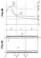
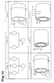
- Fig. 6A is a cross-sectional view of the cylinder liner 2 along the axial direction.
- Fig. 6B shows one example of temperature variation along the axial direction in the cylinder (cylinder wall temperature TW) in a normal operating state of the engine.
- the cylinder liner 2 from which the high thermal conductive film 3 and the low thermal conductive film 4 are removed will be referred to as a reference cylinder liner.
- An engine having the reference cylinder liners will be referred to as a reference engine.
- the positions of the high thermal conductive film 3 and the low thermal conductive film 4 are determined based on the cylinder wall temperature TW in the reference engine.
- the solid line represents the cylinder wall temperature TW of the reference engine
- the broken line represents the cylinder wall temperature of the engine 1 of the present embodiment.
- the highest temperature of the cylinder wall temperature TW is referred to as a maximum cylinder wall temperature TWH
- the lowest temperature of the cylinder wall temperature TW will be referred to as a minimum cylinder wall temperature TWL.
- the cylinder wall temperature TW varies in the following manner.
- the low thermal conductive film 4 is formed on the liner outer circumferential surface 22 in the liner lower portion 26, while the high thermal conductive film 3 is formed on the liner outer circumferential surface 22 in the liner upper portion 25.
- This configuration reduces the difference between the maximum cylinder wall temperature TWH and the minimum cylinder wall temperature TWL (cylinder wall temperature difference ⁇ TW).
- the high thermal conductive film 3 increases the thermal conductivity between the cylinder block 11 and the liner upper portion 25. Accordingly, the cylinder wall temperature TW in the liner upper portion 25 is lowered. This causes the maximum cylinder wall temperature TWH to be a maximum cylinder wall temperature TWH2, which is lower than the maximum cylinder wall temperature TWH1.
- the low thermal conductive film 4 lowers the thermal conductivity between the cylinder block 11 and the liner lower portion 26. Accordingly, the cylinder wall temperature TW in the liner lower portion 26 is increased. This causes the minimum cylinder wall temperature TWL to be a minimum cylinder wall temperature TWL2, which is higher than the minimum cylinder wall temperature TWL1.
- the difference between the maximum cylinder wall temperature TWH and the minimum cylinder wall temperature TWL (cylinder wall temperature difference ⁇ TW) is reduced. Accordingly, variation of deformation of each cylinder bore 15 along the axial direction of the cylinder is reduced (deformation amount is equalized). This reduces the friction and thus improves the fuel consumption rate. Also, the laminated film portion 30 suppresses abrupt changes of the cylinder wall temperature TW in the liner middle portion 27. This further reliably equalizes the amount of deformation of the cylinder bore 15.
- the boundary between the liner upper portion 25 and the liner middle portion 27 can be obtained based on the cylinder wall temperature TW of the reference engine.
- the length of the liner upper portion 25 (the length from the liner upper end 23 to the wall temperature boundary 28) is one third to one quarter of the entire length of the cylinder liner 2 (the length from the liner upper end 23 to the liner lower end 24). Therefore, when determining the position of the high thermal conductive film 3, one third to one quarter range from the liner upper end 23 in the entire liner length may be treated as the liner upper portion 25 without precisely determining the wall temperature boundary 28.
- the thickness of the base film portion 31 of the high thermal conductive film 3 and the thickness of the base film portion 41 of the low thermal conductive film 4 are substantially equal to each other.
- the thickness of the laminated film portion 30 is substantially equal to the thickness of the base film portion 31 of the high thermal conductive film 3 and the thickness of the base film portion 41 of the low thermal conductive film 4. that is, the thickness of the high thermal conductive film 3 and the thickness of the low thermal conductive film 4 are determined such that a film having a substantially constant thickness is formed from the liner upper end 23 to the liner lower end 24.
- the material for the high thermal conductive film 3 a material that meets at least one of the following conditions (A) and (B) may be used.
- any of the following methods may be employed.
- a layer formed by spraying may be adopted as the high thermal conductive film 3.
- the material of the sprayed layer aluminum, an aluminum alloy, copper, or a copper alloy may be mainly used.
- the cylinder block 11 and the cylinder liner 2 are bonded to each in the following manner.
- the liner upper portion 25 and the high thermal conductive film 3 are mechanically bonded to each other with sufficient adhesion and bond strength.
- the adhesion of the liner upper portion 25 and the high thermal conductive film 3 is higher than the adhesion of the cylinder block and the reference cylinder liner in the reference engine.
- the high thermal conductive film 3 is formed of an Al-Si alloy that has a melting point lower than the reference molten metal temperature TC and a high wettability with the casting material of the cylinder block 11.
- the cylinder block 11 and the high thermal conductive film 3 are mechanically bonded to each other with sufficient adhesion and bond strength.
- the adhesion of the cylinder block 11 and the high thermal conductive film 3 is higher than the adhesion of the cylinder block and the reference cylinder liner in the reference engine.
- the amount of gap between these components is increased. Accordingly, the thermal conductivity between the cylinder block 11 and the liner upper portion 25 is reduced. As the bond strength between the cylinder block 11 and the high thermal conductive film 3 and the bond strength between the liner upper portion 25 and the high thermal conductive film 3 are reduced, it is more likely that exfoliation occurs between these components. Therefore, when the cylinder bore 15 is expanded, the adhesion between the cylinder block 11 and the liner upper portion 25 is reduced.
- the high thermal conductive film 3 is melt and metallurgically bonded to the casting material when producing the cylinder block 11.
- the cylinder block 11 as described above was mechanically bonded to the high thermal conductive film 3.
- metallurgically bonded portions were found.
- cylinder block 11 and the high thermal conductive film 3 were mainly bonded in a mechanical manner.
- the inventors also found out the following. That is, even if the casting material and the high thermal conductive film 3 were not metallurgically bonded (or only partly bonded in a metallurgical manner), the adhesion and the bond strength of the cylinder block 11 and the liner upper portion 25 were increased as long as the high thermal conductive film 3 had a melting point less than or equal to the reference molten metal temperature TC. Although the mechanism has not been accurately elucidate, it is believed that the rate of solidification of the casting material is reduced due to the fact that the heat of the casting material is not smoothly removed by the high thermal conductive film 3.
- a layer formed by shot coating may be adopted as the high thermal conductive film 3.
- the material of the shot coating layer aluminum, an aluminum alloy, copper, and zinc may be mainly used.
- the cylinder block 11 and the cylinder liner 2 are bonded to each in the following manner.
- the liner upper portion 25 and the high thermal conductive film 3 are mechanically and metallurgically bonded to each other with sufficient adhesion and bond strength. That is, the liner upper portion 25 and the high thermal conductive film 3 are bonded to each other in a state where mechanically bonded portions and metallurgically bonded portions are mingled.
- the adhesion of the liner upper portion 25 and the high thermal conductive film 3 is higher than the adhesion of the cylinder block and the reference cylinder liner in the reference engine.
- the high thermal conductive film 3 is formed of aluminum that has a melting point lower than the reference molten metal temperature TC and a high wettability with the casting material of the cylinder block 11.
- the cylinder block 11 and the high thermal conductive film 3 are mechanically bonded to each other with sufficient adhesion and bond strength.
- the adhesion of the cylinder block 11 and the high thermal conductive film 3 is higher than the adhesion of the cylinder block and the reference cylinder liner in the reference engine.
- a layer formed by plating may be adopted as the high thermal conductive film 3.
- the material of the plated layer aluminum, an aluminum alloy, copper, or a copper alloy may be mainly used.
- the cylinder block 11 and the cylinder liner 2 are bonded to each other in the following manner.
- the laminated film portion 30 is configured as shown in Fig. 5 .
- the liner upper portion 25 and the high thermal conductive film 3 are mechanically bonded to each other.with sufficient adhesion and bond strength.
- the adhesion of the liner upper portion 25 and the high thermal conductive film 3 is higher than the adhesion of the cylinder block and the reference cylinder liner in the reference engine.
- the high thermal conductive film 3 is formed of a copper alloy that has a melting point higher than the reference molten metal temperature TC.
- the cylinder block 11 and the high thermal conductive film 3 are metallurgically bonded to each other with sufficient adhesion and bond strength.
- the adhesion of the cylinder block 11 and the high thermal conductive film 3 is higher than the adhesion of the cylinder block and the reference cylinder liner in the reference engine.
- the high thermal conductive film 3 basically needs to be formed with a metal having a melting point equal to or less than the reference molten metal temperature TC.
- the cylinder block 11 and the high thermal conductive film 3 are metallurgically bonded to each other in some cases.
- the material for the low thermal conductive film 4 a material that meets at least one of the following conditions (A) and (B) may be used.
- any of the following methods may be employed.
- the low thermal conductive film 4 In the cylinder liner 2, a layer formed by spraying may be adopted as the low thermal conductive film 4.
- the material of the sprayed layer an ceramic material such as alumina and zirconia may be mainly used.
- the low thermal conductive film 4 may be formed of a sprayed layer of an iron based material that includes oxides and a number of pores.
- the cylinder block 11 and the cylinder liner 2 are bonded to each in the following manner.
- the cylinder block 11 and the low thermal conductive film 4 are mechanically bonded to each other in a state of a low thermal conductivity.
- the cylinder block 11 and the liner lower portion 26 are bonded to each other in this state, the following advantages are obtained. That is, since the low thermal conductive film 4 reduces the thermal conductivity between the cylinder block 11 and the liner lower portion 26, the cylinder wall temperature TW in the liner lower portion 26 is increased.
- a layer of a mold release agent for die casting formed by painting may be adopted as the low thermal conductive film 4.
- the mold release agent the following agents may be used.
- a mold release agent obtained by compounding vermiculite, Hitazol, and water glass.
- the cylinder block 11 and the cylinder liner 2 are bonded to each in the following manner.
- the low thermal conductive film 4 is formed of a mold release agent, which has a low adhesion with the cylinder block 11, the cylinder block 11 and the low thermal conductive film 4 are bonded to each other with gaps.
- the cylinder block 11 and the liner lower portion 26 are bonded to each other in this state, the following advantages are obtained. That is, since the gaps reduce the thermal conductivity between the cylinder block 11 and the liner lower portion 26, the cylinder wall temperature TW in the liner lower portion 26 is increased. Also, the mold release agent for die casting used during the production of the cylinder block 11 or a material for such mold release agent can be used. Thus, the number of producing steps and costs are reduced
- a layer of a mold wash for centrifugal casting formed by painting may be adopted as the low thermal conductive film 4.
- the following agents may be used.
- a mold wash containing diatomaceous earth as a major component containing diatomaceous earth as a major component.
- a mold wash containing graphite as a major component is a mold wash containing graphite as a major component.
- the cylinder block 11 and the cylinder liner 2 are bonded to each in the following manner.
- the bonding state of the cylinder block 11 and the low thermal conductive film 4 since the low thermal conductive film 4 is formed of a mold wash, which has a low adhesion with the cylinder block 11, the cylinder block 11 and the low thermal conductive film 4 are bonded to each other with gaps.
- the cylinder block 11 and the liner lower portion 26 are bonded to each other in this state, the following advantages are obtained. That is, since the gaps reduce the thermal conductivity between the cylinder block 11 and the liner lower portion 26, the cylinder wall temperature TW in the liner lower portion 26 is increased. Also, the mold wash for centrifugal casting used during the production of the cylinder liner 2 or a material for such a mold wash can be used. Thus, the number of producing steps and costs are reduced.
- a layer of a metallic paint formed by painting may be adopted as the low thermal conductive film 4.
- the cylinder block 11 and the cylinder liner 2 are bonded to each in the following manner.
- the low thermal conductive film 4 is formed of a metallic paint, which has a low adhesion with the cylinder block 11, the cylinder block 11 and the low thermal conductive film 4 are bonded to each other with gaps.
- the cylinder block 11 and the liner lower portion 26 are bonded to each other in this state, the following advantages are obtained. That is, since the gaps reduce the thermal conductivity between the cylinder block 11 and the liner lower portion 26, the cylinder wall temperature TW in the liner lower portion 26 is increased.
- a layer of a low adhesion agent formed by painting may be adopted as the low thermal conductive film 4.
- the low adhesion agent the following agents may be used.
- a low adhesion agents obtained by compounding graphite, water glass, and water.
- a low adhesion agent obtained by compounding boron nitride and water glass.
- the cylinder block 11 and the cylinder liner 2 are bonded to each in the following manner.
- the cylinder block 11 and the low thermal conductive film 4 are bonded to each other with gaps.
- the cylinder block 11 and the liner lower portion 26 are bonded to each other in this state, the following advantages are obtained. That is, since the gaps reduce the thermal conductivity between the cylinder block 11 and the liner lower portion 26, the cylinder wall temperature TW in the liner lower portion 26 is increased.
- a layer of a high-temperature resin formed by resin coating may be adopted as the low thermal conductive film 4.
- the cylinder block 11 and the cylinder liner 2 are bonded to each in the following manner.
- the cylinder block 11 and the low thermal conductive film 4 are bonded to each other with gaps.
- the cylinder block 11 and the liner lower portion 26 are bonded to each other in this state, the following advantages are obtained. That is, since the gaps reduce the thermal conductivity between the cylinder block 11 and the liner lower portion 26, the cylinder wall temperature TW in the liner lower portion 26 is increased.
- a layer formed by chemical conversion treatment spraying may be adopted as the low thermal conductive film 4.
- the chemical conversion treatment layer the following layers maybe formed.
- a chemical conversion treatment layer of phosphate is a chemical conversion treatment layer of phosphate.
- a chemical conversion treatment layer of ferrosoferric oxide is provided.
- the cylinder block 11 and the cylinder liner 2 are bonded to each in the following manner.
- the laminated film portion 30 is configured as shown in Fig. 5 .
- the cylinder block 11 and the low thermal conductive film 4 are bonded to each other with gaps.
- the cylinder block 11 and the liner lower portion 26 are bonded to each other in this state, the following advantages are obtained. That is, since the gaps reduce the thermal conductivity between the cylinder block 11 and the liner lower portion 26, the cylinder wall temperature TW in the liner lower portion 26 is increased.
- the low thermal conductive film 4 is formed to have a sufficient thickness at the constriction 63 of each of projections 6, which will be described below. Therefore, the gaps are easily formed about the constrictions 63. Accordingly, the thermal conductivity is effectively prevented from being lowered.
- the configuration of the high thermal conductive film 3 and the low thermal conductive film 4 can be difficult to freely selected depending on the method of forming (mainly, plating and chemical conversion treatment). Therefore, when producing the cylinder liner 2 by combining the high thermal conductive film 3 and the low thermal conductive film 4 as necessary, a configuration of the laminated film portion 30 that is suitable for each method needs to be adopted. That is, appropriate setting of the order of formation of the films in accordance with the forming method eliminates the disadvantage of impractical combinations of films.
- the configuration of the laminated film portion 30 is classified into a first lamination configuration and a second lamination configuration.
- the first lamination configuration refers to a configuration in which the high thermal conductive film 3 is located on the liner outer circumferential surface 22, and the low thermal conductive film 4 is located on the high thermal conductive film 3. That is, it corresponds to the laminated film portion 30 shown in Fig. 4 .
- the second lamination configuration refers to a configuration in which the low thermal conductive film 4 is located on the liner outer circumferential surface 22, and the high thermal conductive film 3 is located on the low thermal conductive film 4. That is, it corresponds to the laminated film portion 30 shown in Fig. 5 .
- the configuration (the order of formation of the films) of the laminated film portion 30 suitable for the method for forming the high thermal conductive film 3 and the low thermal conductive film 4 will be described.
- the cylinder liner and the method for manufacturing the same according to the present embodiment provide the following advantages.
- cylinder liner 2 In the cylinder liner 2 according to the present embodiment, sufficient adhesion between the cylinder block 11 and the liner upper portions 25 is established, that is, little gap is created about each liner upper portion 25. This ensures a high thermal conductivity between the cylinder block 11 and the liner upper portions 25. Accordingly, since the cylinder wall temperature TW in the liner upper portion 25.is lowered, the consumption of the engine oil is reduced. Since the consumption of the engine oil is suppressed in this manner, piston rings of a less tension compared to those in the reference engine can be used. This improves the fuel consumption rate.
- the cylinder wall temperature TW in the liner lower portion 26 is increased. This reduces the viscosity of the engine oil on the liner inner circumferential surface 21 of the liner lower portion 26, and thus reduces the friction. Accordingly, the fuel consumption rate is improved.
- the laminated film portion 30 is formed in the liner middle portion 27.
- the position of the laminated film portion may be changed as necessary according to the relationship with the demanded cylinder wall temperature TW.
- the position of the laminated film portion 30 may be selected from the following configurations [A] to [D].
- the method for forming the high thermal conductive film 3 is not limited to the methods shown in the first embodiment (spraying, shot coating, and plating). Any other method may be applied as necessary.
- the method for forming the low thermal conductive film 4 is not limited to the methods shown in the first embodiment (spraying, coating, resin coating, and chemical conversion treatment). Any other method may be applied as necessary.
- the film thickness TP of the high thermal conductive film 3 may be gradually increased from the liner upper end 23 to the liner middle portion 27.
- the thermal conductivity between the cylinder block 11 and the liner upper portion 25 decreases from the liner upper end 23 to the liner middle portion 27.
- the difference of the cylinder wall temperature TW in the liner upper portion 25 along the axial direction is reduced.
- the film thickness TP of the low thermal conductive film 4 may be gradually decreased from the liner lower end 24 to the liner middle portion 27.
- the thermal conductivity between the cylinder block 11 and the liner lower portion 26 increases from the liner lower end 24 to the liner middle portion 27.
- the difference of the cylinder wall temperature TW in the liner lower portion 26 along the axial direction is reduced.
- the configuration of the formation of the high thermal conductive film 3 according to the first embodiment may be modified as shown below. That is, the high thermal conductive film 3 may be formed of any material as long as at least one of the following conditions (A) and (B) is met.
- the configuration of the formation of the low thermal conductive film 4 according to the above embodiments may be modified as shown below. That is, the low thermal conductive film 4 may be formed of any material as long as at least one of the following conditions (A) and (B) is met.
- the low thermal conductive film 4 is formed along the entire circumference of the cylinder liner 2.
- the position of the low thermal conductive film 4 may be changed as shown below. That is, with respect to the direction along which the cylinders 13 are arranged, the film 4 may be omitted from sections of the liner outer circumferential surfaces 22 that face the adjacent cylinder bores 15.
- the low thermal conductive films 4 may be formed in sections except for sections of the liner outer circumferential surfaces 22 that face the liner outer circumferential surfaces 22 of the adjacent cylinder liners 2 with respect to the arrangement direction of the cylinders 13. This configuration provides the following advantages (i) and (ii).
- the thermal conductivity is lowered in sections other than the sections facing the adjacent cylinder bores 15 with respect to the circumferential direction of the cylinder 13.
- the thermal conductivity of the sections facing the adjacent cylinder bores 15 is the same as that of conventional engines. This reduces the difference between the cylinder wall temperature TW in the sections other than the sections facing the adjacent cylinder bores 15 and the cylinder wall temperature TW in the sections facing the adjacent the cylinder bores 15. Accordingly, variation of deformation of each cylinder bore 15 along the circumferential direction is reduced (deformation amount is equalized). This reduces the friction of the piston and thus improves the fuel consumption rate.
- the second embodiment is configured by changing the formation of the films in the cylinder liner according to the first embodiment in the following manner.
- the cylinder liner according to the second embodiment is the same as that of the first embodiment except for the configuration described below.
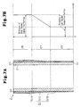
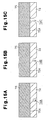
- Fig. 7A is a cross-sectional view of the cylinder liner 2 along the axial direction.
- Fig. 7B shows the relationship between the axial position and the film thickness.
- a film 51 is formed on the liner outer circumferential surface 22 from the liner upper end 23 to the liner lower end 24.
- the film 51 is formed of an A1-Si alloy sprayed layer.
- the film 51 includes a high thermal conductive portion 51A located in the liner upper portion 25, a low thermal conductive portion 51B located in the liner lower portion 26, and an inclined film portion 51C located in the liner middle portion 27.
- the high thermal conductive portion 51A, the low thermal conductive portion 51B, and the inclined film portion 51C are formed as a continuous film.
- the thickness of each portion of the film 51 is set as follows.
- the thickness of the high thermal conductive portion 51A is substantially constant.
- the thickness of the low thermal conductive portion 51B is substantially constant.
- the thickness of the low thermal conductive portion 51B is less than the thickness of the high thermal conductive portion 51A.
- the thickness of the inclined film portion 51C is gradually reduced from the liner upper end 23 toward the liner lower end 24.
- the distance (spraying distance L) between a nozzle of a spraying device 52 and the liner outer circumferential surface 22 is adjusted when forming the film 51 by spraying. That is, a film is formed on the liner outer circumferential surface 22 of the liner lower portion 26 by spraying at a low-rate spraying distance LB, while a film is formed on the liner outer circumferential surface 22 of the liner upper portion 25 by spraying at a reference spraying distance LA.
- the reference spraying distance LA and the low-rate spraying distance LB are set in the following manner.
- the material 53 When performing spraying, some of the material 53 does not collect on the outer circumferential surface 22 but is oxidized about the surface 22. If the deposit efficiency of the spraying material 53 is low, such an oxidized portion of the material 53 is increased. Some of the oxidized portion of the spraying material 53 commingles with a sprayed layer that is being formed on the liner outer circumferential surface 22. Thus, the finishes sprayed layer contains a great amount of oxides in it.
- the spraying distance L is set to the low-rate spraying distance LB
- a sprayed layer containing a great amount of oxides in it is formed on the liner outer circumferential surface 22. That is, a sprayed layer having a low thermal conductivity is formed.
- the spraying distance L is set to the reference spraying distance LA
- a sprayed layer that has a higher thermal conductivity than that in the case where the spraying distance L is set to the low-rate spraying distance LB is formed on the liner outer circumferential surface 22.
- the spraying distance L is set to the low-rate spraying distance LB when forming a sprayed layer on the liner lower portion 26, while the spraying distance L is set to the reference spraying distance LA when forming a sprayed layer on the liner upper portion 25. Therefore, a difference in the thermal conductivity is created between the high thermal conductive portion 51A of the liner upper portion 25 and the low thermal conductive portion 51B of the liner lower portion 26, and the thermal conductivity of the high thermal conductive portion 51A is higher than that of the low thermal conductive portion 51B. This increases the thermal conductivity between the cylinder block 11 and the liner upper portion 25. On the other hand, since the thermal conductivity between the cylinder block 11 and the liner lower portion 26 is reduced, the difference between the maximum cylinder wall temperature TWH and the minimum cylinder wall temperature TWL in the engine 1 is reduced.
- the film 51 may be formed through the following procedure.
- the cylinder liner and the method for manufacturing the same according to the second embodiment provides the following advantage.
- the material for the film 51 a material that meets at least one of the following conditions (A) and (B) may be used.
- the method for forming the film 51 according to the second embodiment may be modified as shown below.
- the reference spraying distance LA is determined as the spraying distance L when the deposit efficiency of the spraying material 53 is maximum.
- the reference spraying distance LA may have a different value.
- any value of the spraying distance L may be adopted as the reference spraying distance LA.
- the third embodiment is configured by changing the structure of the cylinder liner according to the first embodiment in the following manner.
- the cylinder liner according to the third embodiment is the same as that of the first embodiment except for the configuration described below.
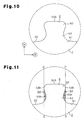
- Fig. 9 is a perspective view illustrating the cylinder liner.
- Projections 6, each having a constricted shape, are formed on the liner outer circumferential surface 22 of the cylinder liner 2.
- the projections 6 are formed on the entire liner outer circumferential surface 22 from an upper end of the cylinder liner 2 (liner upper end 23) to a lower end of the cylinder liner 2 (liner lower end 24).
- a high thermal conductive film 3 and a low thermal conductive film 4 are formed on the liner outer circumferential surface 22, including the surface of the projections 6.
- Fig. 10 is a model diagram showing a projection 6.
- a radial direction of the cylinder liner 2 (direction of arrow A) is referred to as an axial direction of the.projection 6.
- the axial direction of the cylinder liner 2 (direction of arrow B) is referred to as a radial direction of the projection 6.
- Fig. 10 shows the shape of the projection 6 as viewed in the radial direction of the projection 6.
- the projection 6 is integrally formed with the cylinder liner 2.
- the projection 6 is coupled to the liner outer circumferential surface 22 at a proximal end 61.
- a top surface 62A that corresponds to a distal end surface of the projection 6 is formed.
- the top surface 62A is substantially flat.
- a constriction 63 is formed between the proximal end 61 and the distal end 62.
- the constriction 63 is formed such that its cross-sectional area along a radial direction (radial direction cross-sectional area SR) is less than a radial direction cross-sectional area SR at the proximal end 61 and at the distal end 62.
- radial direction cross-sectional area refers to an area of a cross-section perpendicular to the axial direction of the projection 6.
- the projection 6 is formed such that the radial direction cross-sectional area SR gradually increases from the constriction 63 to the proximal end 61 and to the distal end 62.
- Fig. 11 is a model diagram showing the projection 6, in which a constriction space 64 of the cylinder liner 2 is marked.
- each cylinder liner 2 the constriction 63 of each projection 6 creates the constriction space 64 (shaded areas).
- the constriction space 64 is a space surrounded by a curved surface that contains a largest distal portion 62B along the axial direction of the projection 6 (in Fig. 11 , lines D-D corresponds to the curved surface, which is a cylindrical surface) and the surface of the constriction 63 (constriction surface 63A).
- the largest distal portion 62B represents a portion at which the radial length of the projection 6 is the longest in the distal end 62.
- the cylinder block 11 and the cylinder liners 2 are bonded to each other with part of the cylinder block 11 located in the constriction spaces 64 (the cylinder block 11 being engaged with the projections 6). Therefore, sufficient bond strength of the cylinder block 11 and the cylinder liners 2 (liner bond strength) is ensured. Also, since the increased liner bond strength suppresses deformation of the cylinder bores 15, the friction is reduced. Accordingly, the fuel consumption rate is improved.
- the high thermal conductive film 3 and the low thermal conductive film 4 are basically formed in accordance with the configuration similar to that of the first embodiment. Also, since the projections 6 are formed on the liner outer circumferential surface 22, the thicknesses of the high thermal conductive film 3 and the low thermal conductive film 4 are determined in the following manner. The thicknesses of the high thermal conductive film 3 and the low thermal conductive film 4 can be measured by using a microscope.
- the high thermal conductive film 3 is formed such that its thickness TP is less than or equal to 0.5 mm. If the film thickness TP is greater than 0.5 mm, the anchor effect of the projections 6 will be reduced, resulting in a significant reduction in the bond strength between the cylinder block 11 and the liner upper portion 25.
- the high thermal conductive film 3 is formed such that a mean value of the film thickness TP in a plurality of positions of the liner upper portion 25 is less than or equal to 0.5 mm.
- the high thermal conductive film 3 can be formed such that the film thickness TP is less than or equal to 0.5 mm in the entire liner upper portion 25.
- the low thermal conductive film 4 is formed such that its thickness TP is less than or equal to 0.5 mm. If the film thickness TP is greater than 0.5 mm, the anchor effect of the projections 6 will be reduced, resulting in a significant reduction in the bond strength between the cylinder block 11 and the liner lower portion 26.
- the low thermal conductive film 4 is formed such that a mean value of the film thickness TP in a plurality of positions of the liner lower portion 26 is less than or equal to 0.5 mm.
- the low thermal conductive film 4 can be formed such that the film thickness. TP is less than or equal to 0.5 mm in the entire liner lower portion 26.
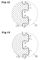
- Fig. 12 shows a cross-sectional structure of encircled part ZD of Fig. 9 .
- the high thermal conductive film 3 is formed on the surfaces of the liner outer circumferential surface 22 and the projections 6. Also, the high thermal conductive film 3 is formed such that the constriction spaces 64 are not filled. That is, the high thermal conductive film 3 is formed such that, when performing the insert casting of the cylinder liners 2, the casting material fills the constriction spaces 64. If the constriction spaces 64 are filled by the high thermal conductive film 3, the casting material will not fill the constriction spaces 64. Thus, no anchor effect of the projections 6 will be obtained in the liner upper portion 25.
- Fig. 13 shows a cross-sectional structure of encircled part ZB of Fig. 9 .
- the low thermal conductive film 4 is formed on the surfaces of the liner outer circumferential surface 22 and the projections 6. Also, the low thermal conductive film 4 is formed such that the constriction spaces 64 are not filled. That is, the low thermal conductive film 4 is formed such that, when performing the insert casting of the cylinder liners 2, the casting material fills the constriction spaces 64. If the constriction spaces 64 are filled by the low thermal conductive film 4, the casting material will not fill the constriction spaces 64. Thus, no anchor effect of the projections 6 will be obtained in the liner lower portion 26.
- a first area ratio SA As parameters representing the formation state of the projection 6 (formation state parameters), a first area ratio SA, a second area ratio SB, a standard cross-sectional area SD, a standard number of projections NP, and a standard projection length HP are defined.
- a measurement height H, a first reference plane PA, and a second reference plane PB, which are basic values for the above formation state parameters, will now be described.
- the formation state parameters [A] to [E] are set to be within the selected ranges in Table 1, so that the liner bond strength of the projections 6 and the filling factor of the casting material between the projections 6 are increased. Since the filling factor of casting material is increased, gaps are unlikely to be created between the cylinder block 11 and the cylinder liners 2. The cylinder block 11 and the cylinder liners 2 are bonded while closing contacting each other.
- the cylinder liner 2 is formed such that the projections 6 are each independently formed on the first reference plane PA. This further increases the adhesion.
- the cylinder liner 2 is produced by centrifugal casting.
- parameters of the centrifugal casting are set be within selected range of Table 2.
- the production of the cylinder liner 2 is executed according to the procedure shown in Fig. 14 .
- Step A The refractory material 71A, the binder 71B, and the water 71C are compounded to prepare the suspension 71.
- the composition ratios of the refractory material 71A, the binder 71B, and the water 71C, and the average particle size of the refractory material 71A are set to fall within the selected ranges in Table 2.
- Step B A predetermined amount of the surfactant 72 is added to the suspension 71 to obtain the mold wash 73.
- the ratio of the added surfactant 72 to the suspension 71 is set to fall within the selected range shown in Table 2.
- Step C After heating the inner circumferential surface of a rotating mold 75 to a predetermined temperature, the mold wash 73 is applied through spraying on an inner circumferential surface of the mold 75 (mold inner circumferential surface 75A). At this time, the mold wash 73 is applied such that a layer of the mold wash 73 (mold wash layer 74) of a substantially uniform thickness is formed on the entire mold inner circumferential surface 75A. In this step, the thickness of'the mold wash layer 74 is set to fall within the selected range shown in Table 2.
- a method for measuring the formation state parameters using a three-dimensional laser will be described.
- the standard projection length HP is measured by another method.
- Each of the formation state parameters can be measured in the following manner.
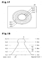
- Fig. 17 is one example of the contour diagram 86.
- Fig. 18 shows the relationship between the measurement height H and contour lines HL.
- the contour diagram 86 of Fig. 17 shows a different projection 6 from that shown in Fig. 18 .
- the contour lines HL are shown at every predetermined value of the measurement height H.
- contour lines HL are shown at a 0.2 mm interval from the measurement height of 0 mm to the measurement height of 1.0 mm in the contour diagram 86.
- contour lines HL0 of the measurement height of 0 mm contour lines HL2 of the measurement height of 0.2 mm, contour lines HL4 of the measurement height of 0.4 mm, contour lines HL6 of the measurement height of 0.6 mm, contour lines HL8 of the measurement height of 0.8 mm, and contour lines HL10 of the measurement height of 1.0 mm are shown.
- the contour line HL 4 corresponds to the first reference plane PA.
- the contour line HL 2 corresponds to the second reference plane PB.
- a diagram is shown in which the contour lines HL are shown at a 0.2 mm interval, the distance between the contour lines HL may be changed as necessary in the actual contour diagram 86.
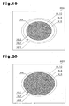
- Fig. 19 is a contour diagram 86 (first contour diagram 86A) in which the contour lines other than the contour lines HL4 of the measurement height 0.4 mm are shown in dotted lines.
- Fig. 20 is a contour diagram 86 (second contour diagram 86B) in which the contour lines other than the contour lines HL2 of the measurement height 0.2 mm are shown in dotted lines.
- solid lines represent the shown contour lines HL
- broken lines represent the other contour lines HL.
- regions each surrounded by the contour line HL4 in the contour diagram 86 are defined as the first regions RA. That is, the shaded areas in the first contour diagram 86A correspond to the first regions RA. Regions each surrounded by the contour line HL2 in the contour diagram 86 are defined as the second regions RB. That is, the shaded areas in the second contour diagram 86B correspond to the second regions RB.
- the formation state parameters are computed in the following manner based on the contour diagram 86.
- the symbol ST represents the area of the entire contour diagram 86.
- the symbol SRA represents the total area obtained by adding up the area of the first region RA in the contour diagram 86.
- the area of the rectangular zone corresponds to the area ST.
- the area of the shaded zone corresponds to the area SRA.
- the contour diagram 86 is assumed to include only the liner outer circumferential surface 22.
- the symbol ST represents the area of the entire contour diagram 86.
- The' symbol SRB represents the total area obtained by adding up the area of the second region RB in the contour diagram 86.
- the area of the rectangular zone corresponds to the area ST.
- the area of the shaded zone corresponds to the area SRB.
- the contour diagram 86 is assumed to include only the liner outer circumferential surface 22.
- the standard cross-sectional area SD can be computed as the area of each first region RA in the contour diagram 86.
- the area of the shaded area corresponds to the standard cross-sectional area SD.
- the standard projection number.NP can be computed as the number of projections 6 per unit area in the contour diagram 86 (in this embodiment, 1 cm 2 ).
- the number of projection in each drawing corresponds to the standard projection number NP.
- the cylinder liner 2 of the present embodiment five to sixty projections 6 are formed per unit area (1 cm 2 ).
- the actual standard projection number NP is different from the reference projection numbers of the first contour diagram 86A and the second contour diagram 86B.
- the standard projection length HP can be computed as a mean value of the heights of the projections 6 at one or more locations.
- the height of the projections 6 can be measured by a measuring device such as a dial depth gauge.
- Whether the projections 6 are independently provided on the first reference plane PA can be checked based on the first regions RA in the contour diagram 86. That is, when the first region RA does not interfere with other first regions RA, it is confirmed that the projections 6 are independently provided on the first reference plane PA.
- the cylinder liner and the engine according to the present embodiment provide the following advantage.
- the standard projection number NP is out of the selected range, the following problems will be caused. If the standard projection number NP is less than five, the number of the projections 6 will be insufficient. This will reduce the liner bond strength. If the standard projection number NP is more than sixty, narrow spaces between the projections 6 will reduce the filing factor of the casting material to spaces between the projections 6.
- the standard projection length HP is out of the selected range, the following problems will be caused. If the standard projection length HP is less 0.5 mm, the height of the projections 6 will be insufficient. This will reduce the liner bond strength. If the standard projection length HP is more 1.0 mm, the projections 6 will be easily broken. This will also reduce the liner bond strength. Also, since the heights of the projection 6 are uneven, the accuracy of the outer diameter is reduced.
- the first area ratio SA is out of the selected range, the following problems will be caused. If the first area ratio SA is less than 10%, the liner bond strength will be significantly reduced compared to the case where the first area ratio SA is more than or equal to 10%. If the first area ratio SA is more than 50%, the second area ratio SB will surpass the upper limit value (55%). Thus, the filling factor of the casting material in the spaces between the projections 6 will be significantly reduced.
- the second area ratio SB is out of the selected range, the following problems will be caused. If the second area ratio SB is less than 20%, the first area ratio SA will fall below the lower limit value (10%). Thus, the liner bond strength will be significantly reduced. If the second area ratio SB is more than 55%, the filling factor of the casting material in the spaces between the projections 6 will be significantly reduced compared to the case where the second area ratio SB is less than or equal to 55%.
- the standard cross-sectional area SD is out of the selected range, the following problems will be caused. If the standard cross-sectional area SD is less than 0.2 mm 2 , the strength of the projections 6 will be insufficient, and the projections 6 will be easily damaged during the production of the cylinder liner 2. If the standard cross-sectional area SD is more than 3.0 mm 2 , narrow spaces between the projections 6 will reduce the filing factor of the casting material to spaces between the projections 6.
- the configuration of the third embodiment may be applied to the cylinder liner 2 of the second embodiment.
- the selected ranges of the first area ratio SA and the second area ratio SB are set to be in the selected ranges shown in Table 1. However, the selected ranges may be changed as shown below.
- the first area ratio SA 10% to 30%
- the second area ratio SB 20% to 45%
- This setting increases the liner bond strength and the filling factor of the casting material to the spaces between the projections 6.
- the high thermal conductive film 3 and the low thermal conductive film 4 are formed on the cylinder liner 2 with the projections 6 the formation parameters of which are in the selected ranges of Table 1.
- the high thermal conductive film 3 and the low thermal conductive film 4 may be formed on any cylinder liner as long as the projections 6 are formed on it.
- the cylinder liner of the present embodiment is applied to an engine made of an aluminum alloy.
- the cylinder liner of the present invention may be applied to an engine made of, for example, a magnesium alloy.
- the cylinder liner of the present invention may be applied to any engine that has a cylinder liner. Even in such case, the advantages similar to those of the above embodiments are obtained if the invention is embodied in a manner similar to the above embodiments.
Landscapes
- Engineering & Computer Science (AREA)
- Mechanical Engineering (AREA)
- Chemical & Material Sciences (AREA)
- Combustion & Propulsion (AREA)
- General Engineering & Computer Science (AREA)
- Cylinder Crankcases Of Internal Combustion Engines (AREA)
- Pistons, Piston Rings, And Cylinders (AREA)
- Coating By Spraying Or Casting (AREA)
Claims (24)
- Zylinderauskleidung zum Einlegegießen, die in einem Zylinderblock verwendet wird, wobei der Zylinderblock eine Außenumfangsfläche und in Bezug auf eine Achsenrichtung der Zylinderauskleidung obere, mittlere und untere Abschnitte aufweist,
wobei ein gut wärmeleitender Überzug in einem Bereich der Außenumfangsfläche, der dem oberen Abschnitt entspricht, gebildet ist, aber nicht in einem Bereich der Außenumfangsfläche gebildet ist, der dem unteren Abschnitt entspricht, und ein schlecht wärmeleitender Überzug in dem Bereich der Außenumfangsfläche gebildet ist, der dem unteren Abschnitt entspricht, aber nicht in dem Bereich der Außenumfangsfläche gebildet ist, der dem oberen Abschnitt entspricht, und wobei der gut wärmeleitende Überzug und der schlecht wärmeleitende Überzug in einem Bereich der Außenumfangsfläche, der dem mittleren Abschnitt entspricht, übereinander gelegt sind, wodurch ein laminierter Überzugsabschnitt gebildet wird. - Zylinderauskleidung nach Anspruch 1, wobei in dem laminierten Überzugsabschnitt der gut wärmeleitende Überzug eine Dicke aufweist, die vom oberen Abschnitt zum unteren Abschnitt allmählich abnimmt.
- Zylinderauskleidung nach Anspruch 1 oder 2, wobei in dem laminierten Überzugsabschnitt der schlecht wärmeleitende Überzug eine Dicke aufweist, die vom oberen Abschnitt zum unteren Abschnitt allmählich abnimmt.
- Zylinderauskleidung nach einem der Ansprüche 1 bis 3, wobei der gut wärmeleitende Überzug dazu dient, die Haftung der Zylinderauskleidung am Zylinderblock zu verstärken.
- Zylinderauskleidung nach einem der Ansprüche 1 bis 4, wobei der gut wärmeleitende Überzug metallurgisch an den Zylinderblock gebunden ist.
- Zylinderauskleidung nach einem der Ansprüche 1 bis 5, wobei der gut wärmeleitende Überzug eine Schmelzpunkt aufweist, der höchstens so hoch ist wie die Temperatur einer Gießschmelze, die beim Einlagegießen der Zylinderauskleidung mit dem Zylinderblock verwendet wird.
- Zylinderauskleidung nach einem der Ansprüche 1 bis 6, wobei der gut wärmeleitende Überzug eine bessere Wärmeleitfähigkeit aufweist als die Zylinderauskleidung.
- Zylinderauskleidung nach einem der Ansprüche 1 bis 7, wobei der gut wärmeleitende Überzug eine bessere Wärmeleitfähigkeit aufweist als der Zylinderblock.
- Zylinderauskleidung nach einem der Ansprüche 1 bis 8, wobei der schlecht wärmeleitende Überzug dazu dient, Lücken zwischen dem Zylinderblock und der Zylinderauskleidung zu bilden.
- Zylinderauskleidung nach einem der Ansprüche 1 bis 9, wobei der schlecht wärmeleitende Überzug dazu dient, die Haftung der Zylinderauskleidung am Zylinderblock abzuschwächen.
- Zylinderauskleidung nach einem der Ansprüche 1 bis 10, wobei der schlecht wärmeleitende Überzug eine schlechtere Wärmeleitfähigkeit aufweist als der Zylinderblock.
- Zylinderauskleidung nach einem der Ansprüche 1 bis 11, wobei der schwach wärmeleitende Überzug eine schlechtere Wärmeleitfähigkeit aufweist als die Zylinderauskleidung.
- Verfahren zum Herstellen einer Zylinderauskleidung zum Einlegegießen, die in einem Zylinderblock verwendet wird, wobei der Zylinderblock eine Außenumfangsfläche und in Bezug auf eine Achsenrichtung der Zylinderauskleidung obere, mittlere und untere Abschnitte aufweist, wobei das Verfahren umfasst:Ausbilden einer Sprühschicht auf der Außenumfangsfläche unter Verwendung einer Sprühvorrichtung, so dass die Sprühschicht vom oberen Abschnitt zum unteren Abschnitt durchgängig ist;Entfernen der Sprühvorrichtung von der Außenumfangsfläche über einen ersten Abstand, wenn die Sprühschicht in einem Bereich der Außenumfangsfläche gebildet wird, der dem oberen Abschnitt entspricht; undEntfernen der Sprühvorrichtung von der Außenumfangsfläche über einen zweiten Abstand, der größer ist als der erste Abstand, wenn die Sprühschicht in einem Bereich der Außenumfangsfläche gebildet wird, der dem unteren Abschnitt entspricht.
- Verfahren nach Anspruch 13, wobei ein Bereich der Sprühschicht, die dem unteren Abschnitt entspricht, eine Dicke aufweist, die geringer ist als die eines Bereichs der Sprühschicht, die dem oberen Abschnitt entspricht.
- Verfahren nach Anspruch 13, wobei in Bezug auf die Achsenrichtung zumindest in einem Teil der Sprühschicht die Dicke der Sprühschicht vom oberen Abschnitt zum unteren Abschnitt allmählich abnimmt.
- Zylinder nach einem der Ansprüche 1 bis 12, wobei die Außenumfangsfläche eine Vielzahl von Vorsprüngen aufweist, die jeweils eine verengte Form aufweisen.
- Zylinder nach Anspruch 16, wobei die Zahl der Vorsprünge fünf bis 60 pro cm2 der Außenumfangsfläche beträgt.
- Zylinderauskleidung nach Anspruch 16 oder 17, wobei die Höhe der einzelnen Vorsprünge 0,5 bis 1,0 mm beträgt.
- Zylinderauskleidung nach einem der Ansprüche 16 bis 18, wobei die Vorsprünge so angeordnet und gebildet sind, dass in einem Konturliniendiagramm der Außenumfangsfläche, das anhand einer dreidimensionalen Lasermesseinrichtung erhalten wird, das Verhältnis der Gesamtfläche an Regionen, die jeweils von einer Konturenlinie umgeben sind, die eine Höhe von 0,4 mm darstellt, zur Fläche des gesamten Konturliniendiagramms mindestens 10 % beträgt.
- Zylinderauskleidung nach einem der Ansprüche 16 bis 19, wobei die Vorsprünge so angeordnet und gebildet sind, dass in einem Konturliniendiagramm der Außenumfangsfläche, das anhand einer dreidimensionalen Lasermesseinrichtung erhalten wird, das Verhältnis der Gesamtfläche an Regionen, die jeweils von einer Konturenlinie umgeben sind, die eine Höhe von 0,2 mm darstellt, zur Fläche des gesamten Konturliniendiagramms höchstens 55 % beträgt.
- Zylinderauskleidung nach einem der Ansprüche 16 bis 18, wobei die Vorsprünge so angeordnet und gebildet sind, dass in einem Konturliniendiagramm der Außenumfangsfläche, das anhand einer dreidimensionalen Lasermesseinrichtung erhalten wird, das Verhältnis der Gesamtfläche an Regionen, die jeweils von einer Konturenlinie umgeben sind, die eine Höhe von 0,4 mm darstellt, zur Fläche des gesamten Konturliniendiagramms 10 bis 50 % beträgt.
- Zylinderauskleidung nach einem der Ansprüche 16 bis 19, wobei die Vorsprünge so angeordnet und gebildet sind, dass in einem Konturliniendiagramm der Außenumfangsfläche, das anhand einer dreidimensionalen Lasermesseinrichtung erhalten wird, das Verhältnis der Gesamtfläche an Regionen, die jeweils von einer Konturenlinie umgeben sind, die eine Höhe von 0,2 mm darstellt, zur Fläche des gesamten Konturliniendiagramms 20 bis 55 % beträgt.
- Zylinderauskleidung nach einem der Ansprüche 16 bis 22, wobei die Vorsprünge so ausgebildet sind, dass in einem Konturliniendiagramm der Außenumfangsfläche, das anhand einer dreidimensionalen Lasermesseinrichtung erhalten wird, die Fläche jeder Region, die von einer Konturenlinie umgeben ist, die eine Höhe von 0,4 mm darstellt, 0,2 bis 3,0 mm2 beträgt.
- Zylinderauskleidung nach einem der Ansprüche 16 bis 23, wobei die Vorsprünge so angeordnet und ausgebildet sind, dass in einem Konturliniendiagramm der Außenumfangsfläche, das von einer dreidimensionalen Lasermesseinrichtung erhalten wird, Regionen, die jeweils von einer Konturenlinie umgeben sind, die eine Höhe von 0,4 mm darstellt, voneinander unabhängig sind.
Applications Claiming Priority (2)
| Application Number | Priority Date | Filing Date | Title |
|---|---|---|---|
| JP2005201002A JP4512002B2 (ja) | 2005-07-08 | 2005-07-08 | シリンダライナ |
| PCT/JP2006/313914 WO2007007815A2 (en) | 2005-07-08 | 2006-07-06 | Cylinder liner and method for manufacturing the same |
Publications (2)
| Publication Number | Publication Date |
|---|---|
| EP1904249A2 EP1904249A2 (de) | 2008-04-02 |
| EP1904249B1 true EP1904249B1 (de) | 2008-11-19 |
Family
ID=37136671
Family Applications (1)
| Application Number | Title | Priority Date | Filing Date |
|---|---|---|---|
| EP06781034A Active EP1904249B1 (de) | 2005-07-08 | 2006-07-06 | Zylinderlaufbüchse und herstellungsverfahren dafür |
Country Status (9)
| Country | Link |
|---|---|
| US (1) | US7685987B2 (de) |
| EP (1) | EP1904249B1 (de) |
| JP (1) | JP4512002B2 (de) |
| KR (1) | KR100981898B1 (de) |
| CN (2) | CN101829778B (de) |
| BR (1) | BRPI0612791B1 (de) |
| DE (1) | DE602006003767D1 (de) |
| RU (1) | RU2373021C2 (de) |
| WO (1) | WO2007007815A2 (de) |
Families Citing this family (25)
| Publication number | Priority date | Publication date | Assignee | Title |
|---|---|---|---|---|
| JP4491385B2 (ja) * | 2005-07-08 | 2010-06-30 | トヨタ自動車株式会社 | 鋳ぐるみ用部品、シリンダブロック及びシリンダライナ製造方法 |
| JP5139685B2 (ja) | 2007-01-26 | 2013-02-06 | パナソニック株式会社 | 積層素子 |
| DE102008048109B4 (de) * | 2008-04-17 | 2015-01-29 | Ks Aluminium-Technologie Gmbh | Verfahren zur Herstellung eines metallischen Bauteils und Verwendung eines Zylinderteils als Grundkörper zur Durchführung des Verfahrens |
| JP5360956B2 (ja) * | 2008-09-19 | 2013-12-04 | 日野自動車株式会社 | 内燃機関及びシリンダライナ |
| JP5651922B2 (ja) * | 2009-03-04 | 2015-01-14 | 日産自動車株式会社 | シリンダブロック及び溶射皮膜形成方法 |
| JP5251715B2 (ja) * | 2009-05-08 | 2013-07-31 | トヨタ自動車株式会社 | 内燃機関 |
| US8783279B2 (en) * | 2009-07-24 | 2014-07-22 | Mogas Industries, Inc. | Tubular member with thermal sleeve liner |
| JP2012067740A (ja) * | 2010-08-25 | 2012-04-05 | Tpr Co Ltd | 鋳包用シリンダライナ |
| JP2012202286A (ja) * | 2011-03-25 | 2012-10-22 | Toyota Industries Corp | 鋳包み用部材及びその製造方法 |
| WO2013025651A1 (en) * | 2011-08-12 | 2013-02-21 | Mcalister Technologies, Llc | Combustion chamber inserts and associated methods of use and manufacture |
| CN103028718A (zh) * | 2011-09-30 | 2013-04-10 | 广西玉柴机器股份有限公司 | 柴油机气缸的铸造方法 |
| US9387567B2 (en) | 2012-09-13 | 2016-07-12 | Electro-Motive Diesel, Inc. | Cylinder liner having three-tiered surface finish |
| WO2015009777A1 (en) | 2013-07-16 | 2015-01-22 | Federal-Mogul Corporation | Cylinder liner with bonding layer |
| CN105492748A (zh) * | 2013-08-30 | 2016-04-13 | 日立工机株式会社 | 发动机以及具备该发动机的发动机作业机 |
| US9945318B2 (en) * | 2015-12-04 | 2018-04-17 | Hyundai Motor Company | Cylinder block |
| KR20170127903A (ko) | 2016-05-13 | 2017-11-22 | 현대자동차주식회사 | 인서트 주조용 실린더 라이너 및 그 제조 방법 |
| US10407761B2 (en) * | 2016-11-04 | 2019-09-10 | GM Global Technology Operations LLC | Strengthening layer attached to cylinder bore |
| US10677189B2 (en) * | 2017-01-27 | 2020-06-09 | ZYNP Group (U.S.A.) Inc. | Cylinder liner having varied thermal conductivity |
| US10780491B2 (en) | 2018-01-11 | 2020-09-22 | Ford Global Technologies, Llc | Aluminum casting design with alloy set cores for improved intermetallic bond strength |
| DE102018202540B4 (de) | 2018-02-20 | 2022-01-27 | Ford Global Technologies, Llc | Motorblock eines Verbrennungsmotors mit optimierten Wärmeleiteigenschaften |
| US20190323448A1 (en) * | 2018-04-19 | 2019-10-24 | GM Global Technology Operations LLC | Cylinder liner for internal combustion engine and method for making cylinder liner |
| CN110894813B (zh) * | 2018-08-22 | 2023-05-02 | 帝伯爱尔株式会社 | 气缸套及其制造方法和使用气缸套的气缸体的制造方法 |
| CN110857671B (zh) * | 2018-08-22 | 2022-03-08 | 帝伯爱尔株式会社 | 气缸套、机体的制造方法以及气缸套的制造方法 |
| EP3951010A4 (de) * | 2019-03-29 | 2022-04-27 | NISSAN MOTOR Co., Ltd. | Filmbildungsverfahren |
| JP7136338B2 (ja) * | 2019-03-29 | 2022-09-13 | 日産自動車株式会社 | 成膜方法 |
Family Cites Families (19)
| Publication number | Priority date | Publication date | Assignee | Title |
|---|---|---|---|---|
| DE760193C (de) * | 1940-02-06 | 1953-06-15 | Bayerische Motoren Werke Ag | Verfahren zur Herstellung von aus Stahl und Leichtmetall zusammengesetzten Koerpern |
| JPS5951668B2 (ja) * | 1981-01-28 | 1984-12-15 | 日本ピストンリング株式会社 | シリンダライナ |
| JPS6252255A (ja) | 1985-08-29 | 1987-03-06 | Kubota Ltd | 圧力コントロ−ル機構 |
| JPH02187251A (ja) * | 1989-01-11 | 1990-07-23 | Mitsubishi Motors Corp | シリンダブロックの鋳造法 |
| US5291862A (en) * | 1992-01-09 | 1994-03-08 | Honda Giken Kogyo Kabushiki Kaisha | Cylinder sleeve assembly used in cylinder block for multi-cylinder internal combustion engine, and forming mold for use in production of sand mold for casting the same |
| US5749331A (en) * | 1992-03-23 | 1998-05-12 | Tecsyn, Inc. | Powdered metal cylinder liners |
| JP2858208B2 (ja) * | 1994-04-20 | 1999-02-17 | 本田技研工業株式会社 | シリンダブロック |
| EP0739668A2 (de) * | 1995-04-26 | 1996-10-30 | Ryobi Ltd. | Zylinderblock und Zylinderbuchse und Verfahren zur deren Herstellung |
| AT1621U1 (de) | 1996-10-16 | 1997-08-25 | Avl Verbrennungskraft Messtech | Brennkraftmaschine mit innerer verbrennung |
| RU2146183C1 (ru) | 1998-06-01 | 2000-03-10 | ОАО "Волжские моторы" | Отливка блока цилиндров двигателя внутреннего сгорания и способ ее получения |
| JP2001200751A (ja) * | 2000-01-18 | 2001-07-27 | Yanmar Diesel Engine Co Ltd | シリンダライナ冷却構造 |
| IT1319899B1 (it) * | 2000-02-10 | 2003-11-12 | Fiat Ricerche | Procedimento per la produzione di un blocco cilindri per un motore acombustione interna. |
| JP2002174140A (ja) * | 2000-12-05 | 2002-06-21 | Yamaha Motor Co Ltd | シリンダスリーブ及び内燃機関用シリンダブロック並びに内燃機関 |
| JP2003053506A (ja) | 2001-08-07 | 2003-02-26 | Toyoda Mach Works Ltd | 成形品を成形装置から搬出し処理装置に搬入する搬送装置 |
| DE10147219B4 (de) * | 2001-09-24 | 2004-02-26 | Daimlerchrysler Ag | Zylinderlaufbuchse einer Brennkraftmaschine |
| JP4210468B2 (ja) * | 2002-05-13 | 2009-01-21 | 本田技研工業株式会社 | 鋳鉄製鋳ぐるみ部材 |
| DE60305691T2 (de) * | 2002-05-13 | 2007-05-31 | Honda Giken Kogyo K.K. | Gusseisernes inneres Glied und Herstrellungsverfahren dafür |
| DE10338386B3 (de) | 2003-08-21 | 2004-12-09 | Daimlerchrysler Ag | Vorgefertigter Rohling eines ringförmigen oder hohlzylindrischen Bauteils zum Eingießen in ein gehäuseförmiges Bauteil einer Hubkolbenmaschine |
| DE10347510B3 (de) * | 2003-10-13 | 2005-04-28 | Federal Mogul Burscheid Gmbh | Zylinderlaufbuchse mit einer zwei Schichten umfassenden Außenbeschichtung und Verfahren zu deren Ein- oder Umgießen zu einem Verbundkörper |
-
2005
- 2005-07-08 JP JP2005201002A patent/JP4512002B2/ja active Active
-
2006
- 2006-07-06 CN CN2010101588559A patent/CN101829778B/zh active Active
- 2006-07-06 RU RU2007149285/02A patent/RU2373021C2/ru active
- 2006-07-06 KR KR1020087000545A patent/KR100981898B1/ko active IP Right Grant
- 2006-07-06 WO PCT/JP2006/313914 patent/WO2007007815A2/en active Application Filing
- 2006-07-06 EP EP06781034A patent/EP1904249B1/de active Active
- 2006-07-06 BR BRPI0612791-6A patent/BRPI0612791B1/pt active IP Right Grant
- 2006-07-06 US US11/480,873 patent/US7685987B2/en active Active
- 2006-07-06 DE DE602006003767T patent/DE602006003767D1/de active Active
- 2006-07-06 CN CN2006800249291A patent/CN101218047B/zh active Active
Also Published As
| Publication number | Publication date |
|---|---|
| CN101829778B (zh) | 2012-03-28 |
| WO2007007815A3 (en) | 2007-05-18 |
| CN101829778A (zh) | 2010-09-15 |
| CN101218047A (zh) | 2008-07-09 |
| EP1904249A2 (de) | 2008-04-02 |
| KR20080021125A (ko) | 2008-03-06 |
| WO2007007815A2 (en) | 2007-01-18 |
| CN101218047B (zh) | 2010-12-01 |
| JP4512002B2 (ja) | 2010-07-28 |
| BRPI0612791A2 (pt) | 2012-01-03 |
| BRPI0612791B1 (pt) | 2014-07-29 |
| DE602006003767D1 (de) | 2009-01-02 |
| US7685987B2 (en) | 2010-03-30 |
| RU2007149285A (ru) | 2009-07-20 |
| US20070012175A1 (en) | 2007-01-18 |
| KR100981898B1 (ko) | 2010-09-13 |
| RU2373021C2 (ru) | 2009-11-20 |
| JP2007016737A (ja) | 2007-01-25 |
Similar Documents
| Publication | Publication Date | Title |
|---|---|---|
| EP1904249B1 (de) | Zylinderlaufbüchse und herstellungsverfahren dafür | |
| EP1902209B1 (de) | Zylinderlaufbuchse und verfahren zu deren herstellung | |
| EP2301691B1 (de) | Zylinderbuchse und Motor | |
| EP1904737B1 (de) | Zylinderlaufbuchse und motor | |
| JP4975131B2 (ja) | シリンダライナの製造方法 | |
| EP2422902A2 (de) | Zylinderlaufbuchse zum Eingießen |
Legal Events
| Date | Code | Title | Description |
|---|---|---|---|
| PUAI | Public reference made under article 153(3) epc to a published international application that has entered the european phase |
Free format text: ORIGINAL CODE: 0009012 |
|
| 17P | Request for examination filed |
Effective date: 20071120 |
|
| AK | Designated contracting states |
Kind code of ref document: A2 Designated state(s): DE FR GB IT TR |
|
| DAX | Request for extension of the european patent (deleted) | ||
| RIN1 | Information on inventor provided before grant (corrected) |
Inventor name: SHIBATA, KOUHEI Inventor name: SATO, TAKASHI,TEIPI INDUSTRY CO., LTD. Inventor name: HORIGOME, MASAMI,TEIPI INDUSTRY CO., LTD. Inventor name: MIHARA, TOSHIHIRO,TEIKOKU PISTON RING CO., LTD. Inventor name: MIYAMOTO, N.,TOYOTA JIDOSHA KABUSHIKI KAISHA Inventor name: YAMASHITA, NOBUYUKI,TEIKOKU PISTON RING CO., LTD. Inventor name: TAKAMI, TOSHIHIRO,TOYOTA JIDOSHA KABUSHIKI KAISHA Inventor name: HIRANO, MASAKI,TOYOTA JIDOSHA KABUSHIKI KAISHA Inventor name: SAITO, GIICHIRO,TEIPI INDUSTRY CO., LTD. |
|
| GRAP | Despatch of communication of intention to grant a patent |
Free format text: ORIGINAL CODE: EPIDOSNIGR1 |
|
| DAX | Request for extension of the european patent (deleted) | ||
| RBV | Designated contracting states (corrected) |
Designated state(s): DE FR GB IT TR |
|
| GRAS | Grant fee paid |
Free format text: ORIGINAL CODE: EPIDOSNIGR3 |
|
| GRAA | (expected) grant |
Free format text: ORIGINAL CODE: 0009210 |
|
| AK | Designated contracting states |
Kind code of ref document: B1 Designated state(s): DE FR GB IT TR |
|
| REG | Reference to a national code |
Ref country code: GB Ref legal event code: FG4D |
|
| REF | Corresponds to: |
Ref document number: 602006003767 Country of ref document: DE Date of ref document: 20090102 Kind code of ref document: P |
|
| PLBE | No opposition filed within time limit |
Free format text: ORIGINAL CODE: 0009261 |
|
| STAA | Information on the status of an ep patent application or granted ep patent |
Free format text: STATUS: NO OPPOSITION FILED WITHIN TIME LIMIT |
|
| 26N | No opposition filed |
Effective date: 20090820 |
|
| REG | Reference to a national code |
Ref country code: GB Ref legal event code: 746 Effective date: 20130412 |
|
| REG | Reference to a national code |
Ref country code: DE Ref legal event code: R084 Ref document number: 602006003767 Country of ref document: DE Effective date: 20130410 |
|
| REG | Reference to a national code |
Ref country code: FR Ref legal event code: PLFP Year of fee payment: 11 |
|
| REG | Reference to a national code |
Ref country code: FR Ref legal event code: PLFP Year of fee payment: 12 |
|
| REG | Reference to a national code |
Ref country code: FR Ref legal event code: PLFP Year of fee payment: 13 |
|
| P01 | Opt-out of the competence of the unified patent court (upc) registered |
Effective date: 20230427 |
|
| PGFP | Annual fee paid to national office [announced via postgrant information from national office to epo] |
Ref country code: IT Payment date: 20230612 Year of fee payment: 18 Ref country code: FR Payment date: 20230510 Year of fee payment: 18 |
|
| PGFP | Annual fee paid to national office [announced via postgrant information from national office to epo] |
Ref country code: TR Payment date: 20230705 Year of fee payment: 18 Ref country code: GB Payment date: 20230518 Year of fee payment: 18 |
|
| PGFP | Annual fee paid to national office [announced via postgrant information from national office to epo] |
Ref country code: DE Payment date: 20230510 Year of fee payment: 18 |