EP1903531B1 - Fahrzeugidentifikation - Google Patents
Fahrzeugidentifikation Download PDFInfo
- Publication number
- EP1903531B1 EP1903531B1 EP07075820.6A EP07075820A EP1903531B1 EP 1903531 B1 EP1903531 B1 EP 1903531B1 EP 07075820 A EP07075820 A EP 07075820A EP 1903531 B1 EP1903531 B1 EP 1903531B1
- Authority
- EP
- European Patent Office
- Prior art keywords
- transponder
- license plate
- slot
- recess
- vehicle
- Prior art date
- Legal status (The legal status is an assumption and is not a legal conclusion. Google has not performed a legal analysis and makes no representation as to the accuracy of the status listed.)
- Active
Links
Images


Classifications
-
- G—PHYSICS
- G08—SIGNALLING
- G08G—TRAFFIC CONTROL SYSTEMS
- G08G1/00—Traffic control systems for road vehicles
- G08G1/01—Detecting movement of traffic to be counted or controlled
- G08G1/017—Detecting movement of traffic to be counted or controlled identifying vehicles
-
- B—PERFORMING OPERATIONS; TRANSPORTING
- B60—VEHICLES IN GENERAL
- B60R—VEHICLES, VEHICLE FITTINGS, OR VEHICLE PARTS, NOT OTHERWISE PROVIDED FOR
- B60R13/00—Elements for body-finishing, identifying, or decorating; Arrangements or adaptations for advertising purposes
- B60R13/10—Registration, licensing, or like devices
-
- B—PERFORMING OPERATIONS; TRANSPORTING
- B60—VEHICLES IN GENERAL
- B60R—VEHICLES, VEHICLE FITTINGS, OR VEHICLE PARTS, NOT OTHERWISE PROVIDED FOR
- B60R25/00—Fittings or systems for preventing or indicating unauthorised use or theft of vehicles
-
- H—ELECTRICITY
- H01—ELECTRIC ELEMENTS
- H01Q—ANTENNAS, i.e. RADIO AERIALS
- H01Q1/00—Details of, or arrangements associated with, antennas
- H01Q1/12—Supports; Mounting means
- H01Q1/22—Supports; Mounting means by structural association with other equipment or articles
- H01Q1/2208—Supports; Mounting means by structural association with other equipment or articles associated with components used in interrogation type services, i.e. in systems for information exchange between an interrogator/reader and a tag/transponder, e.g. in Radio Frequency Identification [RFID] systems
- H01Q1/2216—Supports; Mounting means by structural association with other equipment or articles associated with components used in interrogation type services, i.e. in systems for information exchange between an interrogator/reader and a tag/transponder, e.g. in Radio Frequency Identification [RFID] systems used in interrogator/reader equipment
-
- H—ELECTRICITY
- H01—ELECTRIC ELEMENTS
- H01Q—ANTENNAS, i.e. RADIO AERIALS
- H01Q1/00—Details of, or arrangements associated with, antennas
- H01Q1/44—Details of, or arrangements associated with, antennas using equipment having another main function to serve additionally as an antenna, e.g. means for giving an antenna an aesthetic aspect
-
- H—ELECTRICITY
- H01—ELECTRIC ELEMENTS
- H01Q—ANTENNAS, i.e. RADIO AERIALS
- H01Q13/00—Waveguide horns or mouths; Slot antennas; Leaky-waveguide antennas; Equivalent structures causing radiation along the transmission path of a guided wave
- H01Q13/10—Resonant slot antennas
-
- B—PERFORMING OPERATIONS; TRANSPORTING
- B60—VEHICLES IN GENERAL
- B60R—VEHICLES, VEHICLE FITTINGS, OR VEHICLE PARTS, NOT OTHERWISE PROVIDED FOR
- B60R2325/00—Indexing scheme relating to vehicle anti-theft devices
- B60R2325/10—Communication protocols, communication systems of vehicle anti-theft devices
- B60R2325/105—Radio frequency identification data [RFID]
Definitions
- the invention relates to the identification of vehicles, vehicles also including vessels and airplanes.
- Identification of cars may be desirable for collecting toll, such as at turnpikes or in the form of a congestion charge. Identification may also be desirable in permit systems, such as in case of access to parking lots and access to road networks (wherein for instance certain cars are only allowed to participate in traffic at specific times or on specific days. Identification of vehicles in general may be desirable in connection with tracing and preventing fraud and theft.
- an active or passive transponder in the form of an RFID, comprising an RFID chip having a transmitting antenna and optionally a reception antenna, with which a signal can be transmitted to and/or received from, respectively, permanently positioned detectors and transmitters, or hand terminals, connected to a processing system.
- a printed circuit board including RFID and battery is arranged on a synthetic frame in front of a license plate.
- the printed circuit board is provided with a loop antenna for microwave reception and may be provided with a dipole antenna for transmission.
- the loop antenna is arranged like a circumferential conductive strip in the synthetic carrier frame.
- US 5621571 A discloses an integrated retro-reflective electronic device where an antenna network is integrated within a license plate for electromagnetic communication and may be connected to external electronic modules.
- WO 2006/128448 A1 discloses a license plate where the transponder is formed by a recess in the metal component.
- the invention provides a device for vehicle identification, comprising a license plate for a vehicle, wherein the license plate is made of electrically conductive material and provided with a transponder, particularly an RFID chip, wherein the transponder is electrically coupled to the material of the license plate, according to claim 1.
- An electric coupling according to the invention comprises a coupling via an electrically conductive material, but also a capacitive or inductive coupling.
- the license plate By giving the license plate itself a function such as antenna to the transponder, particularly RFID, use is made of the properties of the material that needs to be present anyway. As a result the placement becomes simple. Provisions outside of the license plate can be reduced to a minimum. Beforehand the transponder can for instance be adapted to the license plate in question. The license plate including transponder can optionally be kept in stock.
- the transponder with its ground connection is electrically coupled to the material of the license plate.
- the transponder can have its own transmitting antenna, wherein the license plate serves as reception antenna.
- the transponder with its ground connection and with its antenna connection is electrically coupled to the material of the license plate.
- the license plate forms both the transmitting antenna and the reception antenna.
- the transponder itself can be supplied without antenna.
- the license plate is provided with a recess, particularly slot-shaped, wherein the connections are electrically coupled on both sides of the recess to the material of the license plate.
- the plate forms a kind of loop antenna, when the slot is open at one end, or a slot antenna when the recess is bounded by a circumferential edge, as is common for slot antennas.
- Occupation of space is kept limited when the transponder is situated at the location of the recess, particularly in the recess.
- the transponder preferably is spaced apart from one end of the slot-shaped recess, which reduces the risk of damage.
- the transponder is directly electrically coupled to the material of the license plate.
- one or more connections of the transponder can be connected to the material of the license plate by means of a conductive material.
- Said connection may also be adapted to be an attachment of the transponder to the license plate.
- the transponder can be connected on the license plate via an electrically insulating layer, for instance by means of a glue connection or a thin tape.
- an electrically insulated layer is placed between the transponder and the license plate, yet the transponder and the license plate are nonetheless electrically coupled via, for instance, a capacitive coupling.
- a further advantage of this embodiment is that the gluing or pasting offers a simple mounting of the transponder on the license plate. Especially to aluminium license plates, as aluminium in general is not easy to weld.
- the transponder can be situated outside of the centre thereof on purpose, in order to maximise the energy transfer. Because the impedance of the slot-shaped recess in the longitudinal direction of the recess varies (the impedance of the recess is at a maximum in the centre and towards the end the impedance approaches nil), the position where the transponder is electrically coupled to the license plate, is chosen such that the slot impedance substantially equals the design impedance, particularly the output impedance of the transponder. At this location a maximum power transfer can take place.
- the invention provides a vehicle provided with an identification device according to the invention.
- the invention provides an identification system for vehicles according to the invention, wherein the system furthermore comprises means for reading the transponder.
- the invention provides a method for identifying a vehicle, according to claim 9.
- the method also comprises the step of the transponder transmitting an identification signal in response to the received radio signal.
- the device according to the invention is able to communicate with a transmitter/receiver unit of a wireless identification system.
- the license plate 1 of figures 1A and 1B has in this example been built up from several layers, namely a base plate 2 of electrically conductive material, for instance aluminium, copper or steel. At the sight side shown in figure 1A , the plate is coated with a coating layer 5, which also provides colour to the license plate. After applying said coating, in this example identification marks 3 have been pressed in the plate 2.
- the license plate 1 is here furthermore provided with mounting apertures 4 with which the license plate 1 can be attached to a vehicle.
- a slot 6 is left open in the material of the base plate 2, shielded by the layer 5.
- the slot 6 is substantially vertically oriented, and has a length L. At both ends the slot 6 ends in broadened areas 7a,b having circular, oval or differently shaped edges. In between the slot 6 has mutually parallel boundary edges 8.
- a broadening 10 is provided in the centre of the slot 6, in which broadening an RFID chip 11 is placed. With both connections 12 and 13, RFID chip 11 is electrically coupled to the material of the base plate 2. Particularly the connections on both sides of the slot 6 are electrically coupled to the material of the base plate 2.
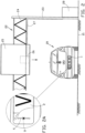
- the base plate 2 When mounted on a vehicle 20 ( figure 2 ), the base plate 2 is shielded from view and from dirt by the layer 5, as is shown in the cut-away view in detail of figure 2A .
- the license plate 1 on the vehicle 20 can then be used in an identification system, see figure 2 , having a portal 22 comprising a column 23 and an outrigger 24 on which for instance a route indication 25 has been arranged. Behind the route indication 25 there is a transmitter/receiver unit 26, transmitting and receiving signals in relation to the RFID on the license plate 1 of the vehicle 20.
- the transmitter/receiver unit 26 By means of the leads 27 the transmitter/receiver unit 26 is connected to a processing unit 28 of the identification system.
- a hand-held hand terminal (not shown) can also be used, which may be offline or able to communicate wirelessly with the processing unit 28.
- the license plate which may for instance have a height in the order of 1 decimetre and a length in the order of a few decimetres, a large range is possible, for instance 30 metres.
- the length L of the slot 6 is approximately half a wavelength of the radio waves.
- the frequency may be 2.4 GHz.
- a vertical orientation of the slot forms the smallest limitation of the surface of the license plate that is available to the signs.
- Figure 3 shows a slot 38 in a license plate 32 that extends along a curved path.
- the antenna operation of the slot 38 is less direction specific and the transponder 31 is able to exchange data more easily with transmission/reception devices that are placed at various positions with respect to the vehicle, for instance along, over or underneath the road.
- Figure 4 shows a slot 48 in a license plate 42 that is adapted to have an antenna operation with a larger band width.
- the transponder 41 is situated outside of the centre of the slot 48 at a position along the slot 48 where the impedance of the slot 48 substantially equals the output impedance of the transponder 41.
Landscapes
- Engineering & Computer Science (AREA)
- Mechanical Engineering (AREA)
- Physics & Mathematics (AREA)
- General Physics & Mathematics (AREA)
- Vehicle Waterproofing, Decoration, And Sanitation Devices (AREA)
- Traffic Control Systems (AREA)
Claims (11)
- Vorrichtung zur Fahrzeugidentifikation, umfassend ein Nummernschild für ein Fahrzeug, wobei das Nummernschild zumindest teilweise aus einem elektrisch leitfähigen Material besteht und mit einem Transponder, insbesondere einem RFID-Chip, versehen ist, wobei der Transponder mit dem Material des Nummernschilds elektrisch gekoppelt ist, wobei der Transponder zwei Anschlüsse umfasst und wobei das Nummernschild mit einer Aussparung versehen ist, wobei die Anschlüsse auf beiden Seiten der Aussparung mit dem Material des Nummernschilds elektrisch gekoppelt sind, wobei die Aussparung schlitzförmig ist, und wobei der Transponder von einem Ende der schlitzförmigen Aussparung beabstandet ist und in Längsrichtung der schlitzförmigen Aussparung außerhalb der Mitte der schlitzförmigen Aussparung in einer Position längs der schlitzförmigen Aussparung angeordnet ist, wo die Impedanz der schlitzförmigen Aussparung im Wesentlichen gleich der Ausgangsimpedanz des Transponders ist.
- Vorrichtung nach Anspruch 1, wobei der Transponder mit seiner Masseverbindung mit dem Material des Nummernschilds elektrisch gekoppelt ist.
- Vorrichtung nach Anspruch 1, wobei die Aussparung von einem Umfangsrand umgrenzt wird.
- Vorrichtung nach Anspruch 1, 3, wobei der Transponder an der Stelle der Aussparung angeordnet ist.
- Vorrichtung nach Anspruch 4, wobei der Transponder in der Aussparung angeordnet ist.
- Vorrichtung nach einem der vorhergehenden Ansprüche, wobei der Transponder mit dem Material des Nummernschilds direkt elektrisch gekoppelt ist.
- Fahrzeug, das mit einer Vorrichtung/einem Nummernschild nach einem der vorhergehenden Ansprüche versehen ist.
- Identifikationssystem für Fahrzeuge, wobei Fahrzeuge mit Vorrichtungen nach einem der Ansprüche 1 bis 6 versehen sind, wobei das System ferner Mittel zum Lesen des Transponders umfassen.
- Verfahren zum Identifizieren eines Fahrzeug, umfassend die folgenden Schritte:Senden eines Funksignals an das Fahrzeug;Empfangen des Funksignals mit Hilfe eines Nummernschilds des Fahrzeugs, wobei das Nummernschild zumindest teilweise aus einem elektrisch leitfähigen Material hergestellt ist und als Empfangsantenne geeignet ist;Übertragen des Funksignals von dem Nummernschild an einen Transponder, insbesondere einen RFID-Chip, wobei der Transponder mit dem Material des Nummernschilds elektrisch gekoppelt ist, wobei der Transponder zwei Anschlüsse umfasst, wobei das Nummernschild mit einer Aussparung versehen ist, wobei die Anschlüsse auf beiden Seiten der Aussparung mit dem Material des Nummernschilds elektrisch gekoppelt sind, wobei die Aussparung schlitzförmig ist, und wobei der Transponder von einem Ende der schlitzförmigen Aussparung beabstandet ist und in Längsrichtung der schlitzförmigen Aussparung außerhalb der Mitte der schlitzförmigen Aussparung in einer Position längs der schlitzförmigen Aussparung angeordnet ist, wo die Impedanz der schlitzförmigen Aussparung im Wesentlichen gleich der Ausgangsimpedanz des Transponders ist.
- Verfahren nach Anspruch 9, ferner umfassend den Schritt des Sendens durch den Transponder eines Identifikationssignals als Reaktion auf das empfangene Funksignal.
- Verfahren nach Anspruch 9, ferner umfassend die folgenden Schritte:Erzeugen eines Identifikationssignals durch den Transponder als Reaktion auf das empfangene Funksignal;Übertragen des Identifikationssignals vom Transponder an das Nummernschild, das als Sendeantenne zum Senden des Identifikationssignals geeignet ist.
Priority Applications (1)
| Application Number | Priority Date | Filing Date | Title |
|---|---|---|---|
| EP19204098.8A EP3618028B1 (de) | 2006-09-20 | 2007-09-20 | Fahrzeugidentifikation |
Applications Claiming Priority (1)
| Application Number | Priority Date | Filing Date | Title |
|---|---|---|---|
| NL1032542A NL1032542C2 (nl) | 2006-09-20 | 2006-09-20 | Voertuigidentificatie. |
Related Child Applications (4)
| Application Number | Title | Priority Date | Filing Date |
|---|---|---|---|
| EP19204098.8A Division EP3618028B1 (de) | 2006-09-20 | 2007-09-20 | Fahrzeugidentifikation |
| EP19204098.8A Division-Into EP3618028B1 (de) | 2006-09-20 | 2007-09-20 | Fahrzeugidentifikation |
| EP18207077.1 Division-Into | 2018-11-19 | ||
| EP23155052.6 Division-Into | 2023-02-06 |
Publications (3)
| Publication Number | Publication Date |
|---|---|
| EP1903531A1 EP1903531A1 (de) | 2008-03-26 |
| EP1903531C0 EP1903531C0 (de) | 2023-08-16 |
| EP1903531B1 true EP1903531B1 (de) | 2023-08-16 |
Family
ID=38016810
Family Applications (2)
| Application Number | Title | Priority Date | Filing Date |
|---|---|---|---|
| EP07075820.6A Active EP1903531B1 (de) | 2006-09-20 | 2007-09-20 | Fahrzeugidentifikation |
| EP19204098.8A Active EP3618028B1 (de) | 2006-09-20 | 2007-09-20 | Fahrzeugidentifikation |
Family Applications After (1)
| Application Number | Title | Priority Date | Filing Date |
|---|---|---|---|
| EP19204098.8A Active EP3618028B1 (de) | 2006-09-20 | 2007-09-20 | Fahrzeugidentifikation |
Country Status (5)
| Country | Link |
|---|---|
| US (1) | US20090058602A1 (de) |
| EP (2) | EP1903531B1 (de) |
| ES (2) | ES2961831T3 (de) |
| NL (1) | NL1032542C2 (de) |
| PL (2) | PL3618028T3 (de) |
Families Citing this family (18)
| Publication number | Priority date | Publication date | Assignee | Title |
|---|---|---|---|---|
| DE102009033559A1 (de) * | 2008-11-04 | 2010-05-06 | J.H. Tönnjes E.A.S.T. GmbH & Co. KG | Kennzeichen für ein Fahrzeug |
| FR2941077B1 (fr) | 2009-01-13 | 2011-03-18 | Ajax Holding | Systeme d'identification pour collecter des donnees provenant d'au moins un vehicule |
| CN101587643B (zh) * | 2009-06-08 | 2010-11-03 | 宁波大学 | 一种套牌车的识别方法 |
| IT1394851B1 (it) * | 2009-07-21 | 2012-07-20 | Winning Time S R L | Dispositivo e sistema per l'identificazione di un veicolo |
| US9346419B2 (en) * | 2012-02-02 | 2016-05-24 | Nippon Carbide Industries Co., Inc. | Sign plate |
| EP2677475B1 (de) * | 2012-06-22 | 2014-11-19 | Join Yiuh Industry Co., Ltd. | Verfahren zur Herstellung eines metallischen Langbereichs-Funkfrequenzidentifizierungsprodukts, und Struktur davon |
| WO2014049579A1 (en) * | 2012-09-28 | 2014-04-03 | KOOIKER, Bouke, Johannes | A motor vehicle licence holder |
| RU2514025C1 (ru) * | 2012-11-16 | 2014-04-27 | Игорь Юрьевич Мацур | Индукционная система обнаружения и идентификации транспортных средств, индукционный регистрационный номерной знак и индукционный считыватель |
| RU2566586C2 (ru) * | 2013-04-22 | 2015-10-27 | Игорь Юрьевич Мацур | Индукционная система обнаружения и идентификации транспортных средств |
| PT107661A (pt) * | 2014-05-27 | 2015-11-27 | Porta Saber Comércio E Serviços De Consultoria Unipessoal Lda | Chapa de matrícula para veículos automóveis com dispositivo de identificação de rádio frequência (rfid) |
| DE102014012291A1 (de) * | 2014-08-22 | 2016-02-25 | Tönnjes Isi Patent Holding Gmbh | Kennzeichen für ein Fahrzeug |
| WO2016164644A1 (en) | 2015-04-07 | 2016-10-13 | Neology, Inc. | Radio frequency identification tag in a license plate |
| US20190058248A1 (en) * | 2017-08-18 | 2019-02-21 | Revivermx, Inc. | Antenna System for a Digital License Plate |
| EP3492325B1 (de) * | 2017-12-01 | 2022-11-16 | Raffaele Iannotta | Elektronisches system zur erkennung und meldung einer unbefugten entfernung eines kennzeichens von einem kraftfahrzeug |
| DE102018002585A1 (de) * | 2018-03-28 | 2019-10-02 | Tönnjes Isi Patent Holding Gmbh | Fahrzeugidentifikationsmittel |
| DE102018007540A1 (de) * | 2018-06-15 | 2019-12-19 | J.H. Tönnjes Gmbh | Verfahren und Vorrichtung zum Ausstatten eines Kennzeichens, vorzugsweise eines Kraftfahrzeug-Kennzeichens, mit einem Datenträger und ein Kennzeichen |
| PL235167B1 (pl) * | 2018-08-03 | 2020-06-01 | Utal Spolka Z Ograniczona Odpowiedzialnoscia | Tablica informacyjna zwłaszcza rejestracyjna |
| EP4184385B1 (de) * | 2021-11-23 | 2025-08-06 | Porta Saber Lda | Informationsplatte und verfahren zur herstellung der informationsplatte |
Citations (4)
| Publication number | Priority date | Publication date | Assignee | Title |
|---|---|---|---|---|
| US5621571A (en) * | 1994-02-14 | 1997-04-15 | Minnesota Mining And Manufacturing Company | Integrated retroreflective electronic display |
| US20020177408A1 (en) * | 2000-03-25 | 2002-11-28 | Forster Ian J. | Multiple feed point slot antenna |
| US20020175818A1 (en) * | 2000-07-18 | 2002-11-28 | King Patrick F. | Wireless communication device and method for discs |
| WO2006128448A1 (de) * | 2005-06-01 | 2006-12-07 | Hardy Zissel | Anordnung mit transponder und metallischem element |
Family Cites Families (24)
| Publication number | Priority date | Publication date | Assignee | Title |
|---|---|---|---|---|
| US4001822A (en) * | 1974-05-28 | 1977-01-04 | Rca Corporation | Electronic license plate for motor vehicles |
| KR920002439B1 (ko) * | 1988-08-31 | 1992-03-24 | 삼성전자 주식회사 | 휴대용 무선전화기의 슬로트 안테나 장치 |
| US5177494A (en) * | 1989-02-16 | 1993-01-05 | Robert Bosch Gmbh | Vehicular slot antenna system |
| JP3336733B2 (ja) * | 1994-04-07 | 2002-10-21 | 株式会社村田製作所 | 移動手段用通信モジュール |
| US5608391A (en) * | 1995-05-11 | 1997-03-04 | Minnesota Mining And Manufacturing Company | Electronic license plate architecture |
| JPH11505647A (ja) * | 1995-05-11 | 1999-05-21 | ミネソタ マイニング アンド マニュファクチャリング カンパニー | 安全識別装置を有する電子ライセンスプレート |
| ES2200388T3 (es) * | 1997-10-14 | 2004-03-01 | Siemens Aktiengesellschaft | Placa de matricula de vehiculos con soporte de datos electronicos legible sin contacto y procedimiento de fabricacion. |
| US6025784A (en) * | 1998-02-12 | 2000-02-15 | Micron Technology, Inc. | Vehicles, license plate frame assemblies, methods of forming license plate frames, and methods of attaching RFIDs, transponders and modulators to vehicles |
| FR2801728A1 (fr) * | 1999-11-26 | 2001-06-01 | Valeo Securite Habitacle | Antenne emettrice de champ magnetique pour vehicule automobile |
| AU775854B2 (en) * | 2000-07-04 | 2004-08-19 | Credipass Co., Ltd. | Passive transponder identification system and credit-card type transponder |
| FR2821463B1 (fr) * | 2001-02-26 | 2003-12-19 | Stid | Dispositif d'authentification de plaques mineralogiques |
| US6758405B2 (en) * | 2001-12-19 | 2004-07-06 | 3M Innovative Properties Company | Article with retroreflective and radio frequency-responsive features |
| US7443299B2 (en) * | 2003-04-25 | 2008-10-28 | Avery Dennison Corporation | Extended range RFID system |
| EP1727112A4 (de) * | 2004-02-27 | 2009-08-05 | Nippon Carbide Kogyo Kk | Anzeigevorrichtung mit diebstahlschutzstruktur |
| US7096102B1 (en) * | 2004-02-27 | 2006-08-22 | Parker Sr Harold C | Motor vehicle license plate with integral wireless tracking and data dissemination device |
| USD562810S1 (en) * | 2004-03-29 | 2008-02-26 | Impinj, Inc. | Radio frequency identification tag antenna assembly |
| EP1769479A1 (de) * | 2004-06-21 | 2007-04-04 | Tory Shane Weber | Verfahren und einrichtung zur erkennung des illegalen betriebs von fahrzeugen |
| EP1864266A2 (de) * | 2005-03-29 | 2007-12-12 | Symbol Technologies, Inc. | Intelligente hochfrequenzidentifikationselemente (rfid) |
| US7619531B2 (en) * | 2005-07-19 | 2009-11-17 | Alien Technology Corporation | Radio frequency identification with a slot antenna |
| JP4787572B2 (ja) * | 2005-08-25 | 2011-10-05 | 株式会社日立製作所 | 無線icタグ、及び無線icタグの製造方法 |
| US7463150B2 (en) * | 2005-10-28 | 2008-12-09 | 3M Innovative Properties Company | Vehicle identification tag and methods of verifying the validity of a vehicle identification tag |
| NZ549173A (en) * | 2006-08-15 | 2007-06-29 | Times 7 Holdings Ltd | Licence plate with integrated antenna |
| MX2009006781A (es) * | 2006-12-21 | 2010-01-15 | Neology Inc | Sistemas y métodos para una placa de metal habilitada con identificación por radio frecuencia. |
| KR101518521B1 (ko) * | 2007-04-18 | 2015-05-07 | 쓰리엠 이노베이티브 프로퍼티즈 캄파니 | 전기 전도성 표지판에 결합된 무선 주파수 식별 기능 |
-
2006
- 2006-09-20 NL NL1032542A patent/NL1032542C2/nl active Search and Examination
-
2007
- 2007-09-19 US US11/901,973 patent/US20090058602A1/en not_active Abandoned
- 2007-09-20 ES ES07075820T patent/ES2961831T3/es active Active
- 2007-09-20 EP EP07075820.6A patent/EP1903531B1/de active Active
- 2007-09-20 ES ES19204098T patent/ES2965900T3/es active Active
- 2007-09-20 PL PL19204098.8T patent/PL3618028T3/pl unknown
- 2007-09-20 EP EP19204098.8A patent/EP3618028B1/de active Active
- 2007-09-20 PL PL07075820.6T patent/PL1903531T3/pl unknown
Patent Citations (4)
| Publication number | Priority date | Publication date | Assignee | Title |
|---|---|---|---|---|
| US5621571A (en) * | 1994-02-14 | 1997-04-15 | Minnesota Mining And Manufacturing Company | Integrated retroreflective electronic display |
| US20020177408A1 (en) * | 2000-03-25 | 2002-11-28 | Forster Ian J. | Multiple feed point slot antenna |
| US20020175818A1 (en) * | 2000-07-18 | 2002-11-28 | King Patrick F. | Wireless communication device and method for discs |
| WO2006128448A1 (de) * | 2005-06-01 | 2006-12-07 | Hardy Zissel | Anordnung mit transponder und metallischem element |
Also Published As
| Publication number | Publication date |
|---|---|
| US20090058602A1 (en) | 2009-03-05 |
| PL1903531T3 (pl) | 2024-02-26 |
| EP3618028C0 (de) | 2023-09-06 |
| EP1903531A1 (de) | 2008-03-26 |
| EP3618028B1 (de) | 2023-09-06 |
| EP1903531C0 (de) | 2023-08-16 |
| EP3618028A1 (de) | 2020-03-04 |
| ES2965900T3 (es) | 2024-04-17 |
| NL1032542C2 (nl) | 2008-03-21 |
| PL3618028T3 (pl) | 2024-03-18 |
| ES2961831T3 (es) | 2024-03-14 |
Similar Documents
| Publication | Publication Date | Title |
|---|---|---|
| EP1903531B1 (de) | Fahrzeugidentifikation | |
| EP3879458A1 (de) | Rfid-wechseletikett | |
| EP1724714A2 (de) | Patchantenne für ein RFID-Etikett | |
| CN202268482U (zh) | 电子不停车收费系统用超高频射频识别读写器天线 | |
| CN100456558C (zh) | 组合天线 | |
| CN214280201U (zh) | 一种车载电子标签 | |
| CN108365321A (zh) | 一种用于rfid系统的定位天线 | |
| KR102694433B1 (ko) | 안테나 모듈 및 이를 구비한 휴대 단말 커버 | |
| CN212848810U (zh) | 一种与v2x设备融合的etc天线 | |
| CN101388491A (zh) | Rfid阅读器微带矩形二单元阵列收发天线 | |
| ZA200802548B (en) | Vehicle identification | |
| CN214280196U (zh) | 一种汽车玻璃集成天线 | |
| CN214336938U (zh) | 一种有源天线及车载电子标签 | |
| JP4460706B2 (ja) | ゲートシステム | |
| CN204087283U (zh) | 车载单元 | |
| CN207624910U (zh) | 一种陷波结构的微带天线和车载电子标签 | |
| CN221596747U (zh) | 一种车标天线装置及分体式车载单元 | |
| JPH07282211A (ja) | 非接触icカード式送受信装置 | |
| JP4844385B2 (ja) | 無線通信システム | |
| CN107039749A (zh) | 车载天线 | |
| CN215182089U (zh) | 一种车载电子标签 | |
| CN217718736U (zh) | Etc车载装置 | |
| KR200409485Y1 (ko) | 아이티에스용 차량 탑재 단말기 | |
| EP4184386B1 (de) | Informationsplatte und verfahren zur herstellung der informationsplatte | |
| KR100685381B1 (ko) | 아이티에스용 차량 탑재 단말기 |
Legal Events
| Date | Code | Title | Description |
|---|---|---|---|
| PUAI | Public reference made under article 153(3) epc to a published international application that has entered the european phase |
Free format text: ORIGINAL CODE: 0009012 |
|
| AK | Designated contracting states |
Kind code of ref document: A1 Designated state(s): AT BE BG CH CY CZ DE DK EE ES FI FR GB GR HU IE IS IT LI LT LU LV MC MT NL PL PT RO SE SI SK TR |
|
| AX | Request for extension of the european patent |
Extension state: AL BA HR MK YU |
|
| 17P | Request for examination filed |
Effective date: 20080923 |
|
| AKX | Designation fees paid |
Designated state(s): AT BE BG CH CY CZ DE DK EE ES FI FR GB GR HU IE IS IT LI LT LU LV MC MT NL PL PT RO SE SI SK TR |
|
| AXX | Extension fees paid |
Extension state: HR Payment date: 20080923 Extension state: MK Payment date: 20080923 Extension state: RS Payment date: 20080923 |
|
| 17Q | First examination report despatched |
Effective date: 20081112 |
|
| STAA | Information on the status of an ep patent application or granted ep patent |
Free format text: STATUS: EXAMINATION IS IN PROGRESS |
|
| GRAP | Despatch of communication of intention to grant a patent |
Free format text: ORIGINAL CODE: EPIDOSNIGR1 |
|
| STAA | Information on the status of an ep patent application or granted ep patent |
Free format text: STATUS: GRANT OF PATENT IS INTENDED |
|
| INTG | Intention to grant announced |
Effective date: 20190111 |
|
| GRAJ | Information related to disapproval of communication of intention to grant by the applicant or resumption of examination proceedings by the epo deleted |
Free format text: ORIGINAL CODE: EPIDOSDIGR1 |
|
| STAA | Information on the status of an ep patent application or granted ep patent |
Free format text: STATUS: EXAMINATION IS IN PROGRESS |
|
| INTC | Intention to grant announced (deleted) | ||
| APBK | Appeal reference recorded |
Free format text: ORIGINAL CODE: EPIDOSNREFNE |
|
| APBN | Date of receipt of notice of appeal recorded |
Free format text: ORIGINAL CODE: EPIDOSNNOA2E |
|
| APBR | Date of receipt of statement of grounds of appeal recorded |
Free format text: ORIGINAL CODE: EPIDOSNNOA3E |
|
| APAF | Appeal reference modified |
Free format text: ORIGINAL CODE: EPIDOSCREFNE |
|
| APBT | Appeal procedure closed |
Free format text: ORIGINAL CODE: EPIDOSNNOA9E |
|
| GRAP | Despatch of communication of intention to grant a patent |
Free format text: ORIGINAL CODE: EPIDOSNIGR1 |
|
| STAA | Information on the status of an ep patent application or granted ep patent |
Free format text: STATUS: GRANT OF PATENT IS INTENDED |
|
| INTG | Intention to grant announced |
Effective date: 20230303 |
|
| GRAS | Grant fee paid |
Free format text: ORIGINAL CODE: EPIDOSNIGR3 |
|
| GRAA | (expected) grant |
Free format text: ORIGINAL CODE: 0009210 |
|
| STAA | Information on the status of an ep patent application or granted ep patent |
Free format text: STATUS: THE PATENT HAS BEEN GRANTED |
|
| AK | Designated contracting states |
Kind code of ref document: B1 Designated state(s): AT BE BG CH CY CZ DE DK EE ES FI FR GB GR HU IE IS IT LI LT LU LV MC MT NL PL PT RO SE SI SK TR |
|
| REG | Reference to a national code |
Ref country code: GB Ref legal event code: FG4D |
|
| REG | Reference to a national code |
Ref country code: CH Ref legal event code: EP Ref country code: DE Ref legal event code: R096 Ref document number: 602007061733 Country of ref document: DE |
|
| REG | Reference to a national code |
Ref country code: IE Ref legal event code: FG4D |
|
| U01 | Request for unitary effect filed |
Effective date: 20230915 |
|
| U07 | Unitary effect registered |
Designated state(s): AT BE BG DE DK EE FI FR IT LT LU LV MT NL PT SE SI Effective date: 20230921 |
|
| U20 | Renewal fee for the european patent with unitary effect paid |
Year of fee payment: 17 Effective date: 20231020 |
|
| PG25 | Lapsed in a contracting state [announced via postgrant information from national office to epo] |
Ref country code: GR Free format text: LAPSE BECAUSE OF FAILURE TO SUBMIT A TRANSLATION OF THE DESCRIPTION OR TO PAY THE FEE WITHIN THE PRESCRIBED TIME-LIMIT Effective date: 20231117 |
|
| PG25 | Lapsed in a contracting state [announced via postgrant information from national office to epo] |
Ref country code: IS Free format text: LAPSE BECAUSE OF FAILURE TO SUBMIT A TRANSLATION OF THE DESCRIPTION OR TO PAY THE FEE WITHIN THE PRESCRIBED TIME-LIMIT Effective date: 20231216 |
|
| PG25 | Lapsed in a contracting state [announced via postgrant information from national office to epo] |
Ref country code: IS Free format text: LAPSE BECAUSE OF FAILURE TO SUBMIT A TRANSLATION OF THE DESCRIPTION OR TO PAY THE FEE WITHIN THE PRESCRIBED TIME-LIMIT Effective date: 20231216 Ref country code: GR Free format text: LAPSE BECAUSE OF FAILURE TO SUBMIT A TRANSLATION OF THE DESCRIPTION OR TO PAY THE FEE WITHIN THE PRESCRIBED TIME-LIMIT Effective date: 20231117 |
|
| REG | Reference to a national code |
Ref country code: ES Ref legal event code: FG2A Ref document number: 2961831 Country of ref document: ES Kind code of ref document: T3 Effective date: 20240314 |
|
| PG25 | Lapsed in a contracting state [announced via postgrant information from national office to epo] |
Ref country code: RO Free format text: LAPSE BECAUSE OF FAILURE TO SUBMIT A TRANSLATION OF THE DESCRIPTION OR TO PAY THE FEE WITHIN THE PRESCRIBED TIME-LIMIT Effective date: 20230816 Ref country code: CZ Free format text: LAPSE BECAUSE OF FAILURE TO SUBMIT A TRANSLATION OF THE DESCRIPTION OR TO PAY THE FEE WITHIN THE PRESCRIBED TIME-LIMIT Effective date: 20230816 Ref country code: SK Free format text: LAPSE BECAUSE OF FAILURE TO SUBMIT A TRANSLATION OF THE DESCRIPTION OR TO PAY THE FEE WITHIN THE PRESCRIBED TIME-LIMIT Effective date: 20230816 |
|
| REG | Reference to a national code |
Ref country code: CH Ref legal event code: PL |
|
| REG | Reference to a national code |
Ref country code: DE Ref legal event code: R097 Ref document number: 602007061733 Country of ref document: DE |
|
| PG25 | Lapsed in a contracting state [announced via postgrant information from national office to epo] |
Ref country code: MC Free format text: LAPSE BECAUSE OF FAILURE TO SUBMIT A TRANSLATION OF THE DESCRIPTION OR TO PAY THE FEE WITHIN THE PRESCRIBED TIME-LIMIT Effective date: 20230816 |
|
| PLBE | No opposition filed within time limit |
Free format text: ORIGINAL CODE: 0009261 |
|
| STAA | Information on the status of an ep patent application or granted ep patent |
Free format text: STATUS: NO OPPOSITION FILED WITHIN TIME LIMIT |
|
| PG25 | Lapsed in a contracting state [announced via postgrant information from national office to epo] |
Ref country code: CH Free format text: LAPSE BECAUSE OF NON-PAYMENT OF DUE FEES Effective date: 20230930 |
|
| 26N | No opposition filed |
Effective date: 20240517 |
|
| PG25 | Lapsed in a contracting state [announced via postgrant information from national office to epo] |
Ref country code: CH Free format text: LAPSE BECAUSE OF NON-PAYMENT OF DUE FEES Effective date: 20230930 |
|
| U20 | Renewal fee for the european patent with unitary effect paid |
Year of fee payment: 18 Effective date: 20240709 |
|
| PG25 | Lapsed in a contracting state [announced via postgrant information from national office to epo] |
Ref country code: HU Free format text: LAPSE BECAUSE OF FAILURE TO SUBMIT A TRANSLATION OF THE DESCRIPTION OR TO PAY THE FEE WITHIN THE PRESCRIBED TIME-LIMIT; INVALID AB INITIO Effective date: 20070920 |
|
| PG25 | Lapsed in a contracting state [announced via postgrant information from national office to epo] |
Ref country code: CY Free format text: LAPSE BECAUSE OF FAILURE TO SUBMIT A TRANSLATION OF THE DESCRIPTION OR TO PAY THE FEE WITHIN THE PRESCRIBED TIME-LIMIT; INVALID AB INITIO Effective date: 20070920 |
|
| PGFP | Annual fee paid to national office [announced via postgrant information from national office to epo] |
Ref country code: TR Payment date: 20250911 Year of fee payment: 19 Ref country code: PL Payment date: 20250905 Year of fee payment: 19 |
|
| PGFP | Annual fee paid to national office [announced via postgrant information from national office to epo] |
Ref country code: GB Payment date: 20250923 Year of fee payment: 19 |
|
| PGFP | Annual fee paid to national office [announced via postgrant information from national office to epo] |
Ref country code: IE Payment date: 20250919 Year of fee payment: 19 |
|
| U20 | Renewal fee for the european patent with unitary effect paid |
Year of fee payment: 19 Effective date: 20250924 |
|
| PGFP | Annual fee paid to national office [announced via postgrant information from national office to epo] |
Ref country code: ES Payment date: 20251020 Year of fee payment: 19 |