EP1903418B1 - Vorrichtung zur Umwandlung mechanischer Bewegungen in elektrische Signale - Google Patents
Vorrichtung zur Umwandlung mechanischer Bewegungen in elektrische Signale Download PDFInfo
- Publication number
- EP1903418B1 EP1903418B1 EP07011747.8A EP07011747A EP1903418B1 EP 1903418 B1 EP1903418 B1 EP 1903418B1 EP 07011747 A EP07011747 A EP 07011747A EP 1903418 B1 EP1903418 B1 EP 1903418B1
- Authority
- EP
- European Patent Office
- Prior art keywords
- control stick
- housing
- signal transmitters
- case
- joystick
- Prior art date
- Legal status (The legal status is an assumption and is not a legal conclusion. Google has not performed a legal analysis and makes no representation as to the accuracy of the status listed.)
- Not-in-force
Links
Images




Classifications
-
- G—PHYSICS
- G05—CONTROLLING; REGULATING
- G05G—CONTROL DEVICES OR SYSTEMS INSOFAR AS CHARACTERISED BY MECHANICAL FEATURES ONLY
- G05G9/00—Manually-actuated control mechanisms provided with one single controlling member co-operating with two or more controlled members, e.g. selectively, simultaneously
- G05G9/02—Manually-actuated control mechanisms provided with one single controlling member co-operating with two or more controlled members, e.g. selectively, simultaneously the controlling member being movable in different independent ways, movement in each individual way actuating one controlled member only
- G05G9/04—Manually-actuated control mechanisms provided with one single controlling member co-operating with two or more controlled members, e.g. selectively, simultaneously the controlling member being movable in different independent ways, movement in each individual way actuating one controlled member only in which movement in two or more ways can occur simultaneously
- G05G9/047—Manually-actuated control mechanisms provided with one single controlling member co-operating with two or more controlled members, e.g. selectively, simultaneously the controlling member being movable in different independent ways, movement in each individual way actuating one controlled member only in which movement in two or more ways can occur simultaneously the controlling member being movable by hand about orthogonal axes, e.g. joysticks
-
- G—PHYSICS
- G05—CONTROLLING; REGULATING
- G05G—CONTROL DEVICES OR SYSTEMS INSOFAR AS CHARACTERISED BY MECHANICAL FEATURES ONLY
- G05G7/00—Manually-actuated control mechanisms provided with one single controlling member co-operating with one single controlled member; Details thereof
- G05G7/02—Manually-actuated control mechanisms provided with one single controlling member co-operating with one single controlled member; Details thereof characterised by special provisions for conveying or converting motion, or for acting at a distance
-
- G—PHYSICS
- G05—CONTROLLING; REGULATING
- G05G—CONTROL DEVICES OR SYSTEMS INSOFAR AS CHARACTERISED BY MECHANICAL FEATURES ONLY
- G05G9/00—Manually-actuated control mechanisms provided with one single controlling member co-operating with two or more controlled members, e.g. selectively, simultaneously
- G05G9/02—Manually-actuated control mechanisms provided with one single controlling member co-operating with two or more controlled members, e.g. selectively, simultaneously the controlling member being movable in different independent ways, movement in each individual way actuating one controlled member only
- G05G9/04—Manually-actuated control mechanisms provided with one single controlling member co-operating with two or more controlled members, e.g. selectively, simultaneously the controlling member being movable in different independent ways, movement in each individual way actuating one controlled member only in which movement in two or more ways can occur simultaneously
- G05G9/047—Manually-actuated control mechanisms provided with one single controlling member co-operating with two or more controlled members, e.g. selectively, simultaneously the controlling member being movable in different independent ways, movement in each individual way actuating one controlled member only in which movement in two or more ways can occur simultaneously the controlling member being movable by hand about orthogonal axes, e.g. joysticks
- G05G2009/0474—Manually-actuated control mechanisms provided with one single controlling member co-operating with two or more controlled members, e.g. selectively, simultaneously the controlling member being movable in different independent ways, movement in each individual way actuating one controlled member only in which movement in two or more ways can occur simultaneously the controlling member being movable by hand about orthogonal axes, e.g. joysticks characterised by means converting mechanical movement into electric signals
- G05G2009/04748—Position sensor for rotary movement, e.g. potentiometer
-
- G—PHYSICS
- G05—CONTROLLING; REGULATING
- G05G—CONTROL DEVICES OR SYSTEMS INSOFAR AS CHARACTERISED BY MECHANICAL FEATURES ONLY
- G05G9/00—Manually-actuated control mechanisms provided with one single controlling member co-operating with two or more controlled members, e.g. selectively, simultaneously
- G05G9/02—Manually-actuated control mechanisms provided with one single controlling member co-operating with two or more controlled members, e.g. selectively, simultaneously the controlling member being movable in different independent ways, movement in each individual way actuating one controlled member only
- G05G9/04—Manually-actuated control mechanisms provided with one single controlling member co-operating with two or more controlled members, e.g. selectively, simultaneously the controlling member being movable in different independent ways, movement in each individual way actuating one controlled member only in which movement in two or more ways can occur simultaneously
- G05G9/047—Manually-actuated control mechanisms provided with one single controlling member co-operating with two or more controlled members, e.g. selectively, simultaneously the controlling member being movable in different independent ways, movement in each individual way actuating one controlled member only in which movement in two or more ways can occur simultaneously the controlling member being movable by hand about orthogonal axes, e.g. joysticks
- G05G2009/0474—Manually-actuated control mechanisms provided with one single controlling member co-operating with two or more controlled members, e.g. selectively, simultaneously the controlling member being movable in different independent ways, movement in each individual way actuating one controlled member only in which movement in two or more ways can occur simultaneously the controlling member being movable by hand about orthogonal axes, e.g. joysticks characterised by means converting mechanical movement into electric signals
- G05G2009/04755—Magnetic sensor, e.g. hall generator, pick-up coil
-
- G—PHYSICS
- G05—CONTROLLING; REGULATING
- G05G—CONTROL DEVICES OR SYSTEMS INSOFAR AS CHARACTERISED BY MECHANICAL FEATURES ONLY
- G05G9/00—Manually-actuated control mechanisms provided with one single controlling member co-operating with two or more controlled members, e.g. selectively, simultaneously
- G05G9/02—Manually-actuated control mechanisms provided with one single controlling member co-operating with two or more controlled members, e.g. selectively, simultaneously the controlling member being movable in different independent ways, movement in each individual way actuating one controlled member only
- G05G9/04—Manually-actuated control mechanisms provided with one single controlling member co-operating with two or more controlled members, e.g. selectively, simultaneously the controlling member being movable in different independent ways, movement in each individual way actuating one controlled member only in which movement in two or more ways can occur simultaneously
- G05G9/047—Manually-actuated control mechanisms provided with one single controlling member co-operating with two or more controlled members, e.g. selectively, simultaneously the controlling member being movable in different independent ways, movement in each individual way actuating one controlled member only in which movement in two or more ways can occur simultaneously the controlling member being movable by hand about orthogonal axes, e.g. joysticks
- G05G2009/0474—Manually-actuated control mechanisms provided with one single controlling member co-operating with two or more controlled members, e.g. selectively, simultaneously the controlling member being movable in different independent ways, movement in each individual way actuating one controlled member only in which movement in two or more ways can occur simultaneously the controlling member being movable by hand about orthogonal axes, e.g. joysticks characterised by means converting mechanical movement into electric signals
- G05G2009/04759—Light-sensitive detector, e.g. photoelectric
Definitions
- the invention relates to a device for converting mechanical movements into electrical signals, which serve for process control, according to the preamble of claim 1.
- the magnetically conductive sheet terminates in the region of the respective Hall sensor, so that the movements of the pole pieces, so the changes in the magnetic field upon actuation of the joystick, can be determined by this.
- the thus evaluated magnetic signals are then converted into electrical signals, for example by a microprocessor, and passed on to an electrical unit for their litigation.
- the movements of the joystick can first in changes of a magnetic field and then in electrical signal be converted to litigation. Accordingly, by such a joystick device, control signals can be transmitted to a screen or the like.
- the joystick is tiltably mounted in a housing.
- the housing facing the free end of the joystick is drivingly connected to a variety of mechanical components, such as gears, return springs and mounting shoes connected.
- the movements of the joystick are therefore converted into rotational movements of the gears and in length of the return spring.
- These mechanical components are connected to actuators, through which the rotational movement of the gears and the changes in length of the return springs are measurable.
- the mechanical measurement signals generated in this way can be converted into electrical signals which map the movement changes of the joystick and can be used in corresponding electrical devices for their control.
- the arms connected to the control stick can perform relative movements in the area of the Hall sensors when the control stick is tilted. Also by this conversion device rotational movements or superimpositions of tilting and rotational movements are not transferable to the arms on which the magnets are arranged in the Hall sensors, such rotation or overlay movements can not measure.
- the position of each signal generator is precisely defined in the housing and is subject to any changes during a longer period of operation by force or other shocks. Furthermore, the assignment of the signal generator in the region of the mounted on a printed circuit board receiving sensors is exactly vorappelbar, so that the setting of the field changes or the sensor signal is not subject to unwanted fluctuations even with a longer operating time. Namely, since the distance between the signal transmitters, which are fixedly supported on the drivers and the mounted on the circuit board receiving sensors is maintained constant, the distance between these components remains unchanged after assembly, so that by the one-time adjustment and calibration of the device reliable and accurate operation is possible.
- FIG. 1 For example, a device 1 for converting mechanical movements of a control stick 3 which is tiltable and rotatably mounted in a housing 2 can be taken. By the movements of the joystick 3 electrical signals are to be generated, which serve for a process control, for example on a computer screen, and which are modeled on the visible movement of an arrow or the like.
- a ball 7 is integrally formed on the control stick 3 in the lower region arranged in the housing, which ball acts as a bearing for the control stick 3 in the housing 2.
- the ball 7 of the joystick 3 is thereby encompassed by two guide plates 5 and 6 and held in these rotatable and tiltable.
- the guide plates 5 and 6 are supported on the housing 2 via screws 19 and nuts 21.
- the guide plates 5 and 6 are closed to the outside by a cover 4 and a closure housing 24.
- a bellows not shown, can be pushed onto the closure housing 24.
- the joystick 3 passes through the cover 4 and the end housing 24, so that it is manually accessible from the outside.
- the end housing 24 exerts a restoring force on the control stick 3, by which this is transferred to the starting position.
- a plate 15 is fixedly attached to the ends ending in the housing 2 lower portion of the joystick 3, projecting from the four pins 16.
- the housing 2 has four round recesses 10, in each of which a driver 11 is inserted.
- the carriers 11 are designed to be open in the direction of a printed circuit board 17 accommodated in the housing 2, and in each case a permanent magnet 8 or 9 is inserted in such a way that two adjacent permanent magnets 8 or 9 are poled differently, so that they produce a magnetic field of a different design.
- circuit board 17 On the circuit board 17 are four magnetic sensors, which are constructed as so-called Hall sensors 18, mounted. The position of the respective Hall sensors 18 is associated with the respective permanent magnet 8 or 9, so that the permanent magnets 8 or 9 extend directly above and in alignment with the Hall sensors 18.
- FIGS. 2 to 4 can be seen that in a movement of the joystick 3 in a plane, the driver 11 are changed over the intermediate members 12 in the housing 2 in position, because the drivers 11 are rotatably mounted in the housing 2, so that by a tilting movement and / or a rotation of the joystick 3 a change in position of the respective driver 11 is generated. Due to the rotation and the associated change in angle of the driver 11 relative to the sensors 18, however, the magnetic field generated by the permanent magnets 8 or 9 is also changed directly in the region of the Hall sensors 18. The Hall sensors 18 thus measure the magnetic field changes and pass them on to an electrical evaluation device, which is assigned to the printed circuit board 17, for example a microprocessor or a differently constructed arithmetic unit.
- the magnetic signals of the Hall sensors 18 can be converted into electrical signals in such a way that a movement of an arrow on a screen can be recognized by means of them, or that specific input commands are transmitted and forwarded by the control stick 3.
- a partition plate 34 is inserted, by which the drivers 11 are supported in the housing 2.
- FIG. 4 It is shown that the four pins 16 are movably inserted in the respective elongated hole 14 of the webs 13, so that the respective pins 16 are moved in the oblong holes 14 by the movement of the control stick 3 and thereby a rotational movement of the driver 11 and thus the permanent magnets. 8 or 9 is created. It is conceivable to accommodate only two permanent magnets 8 or 9 in each case two drivers 11. The additional pair of permanent magnets 8 or 9 serve either operational safety when the first pair of permanent magnets 8 and 9 fail or for additional measurements of rotational movements.
- the rotation and / or tilting of the joystick 3 namely that of four drivers 11 are moved in the same direction of rotation; this is detected by the computing and evaluation and converted into corresponding electrical signals. If the joystick 3 additionally or exclusively tilted, each of the tilting movement opposite carriers 11 move in opposite direction of rotation to each other.
- FIGS. 5 to 7 can be seen that at the housed in the housing 2 free end of the joystick 3, the plate 15 'is fixedly mounted, in which now four guide grooves 33 are incorporated.
- the free end of the control stick 3 are facing, so protrude into the center of the housing 2.
- the free ends of the pins 31 are as Ball head 32 formed and inserted into the respective guide groove 33.
- the respective ball heads 32 can be moved longitudinally displaceably in the guide groove 33, so that the mechanical transmission of the direction of movement of the control stick 3 to the drivers 11 is ensured.
- the width of the guide grooves 33 corresponds to the diameter of the ball heads 32 inserted therein.
- a plurality of electrical lines 36 are provided in the interior of the joystick 3, which are connected to a mounted on the free outwardly projecting end of the joystick control knob 3 or button.
- the electrical signals generated by the rotation of the knob or by the operation of the button are transmitted to the circuit board 17 through the lines 36 and moved from an attached on the circuit board 17 electrical computing unit and converted into electrical signals.
- the exit of the electrical lines 36 from the joystick 3 takes place directly in the interior of the housing 2 and at a small distance to the tilting plane 35 of the joystick 3, so that the electrical lines 36 are advantageously exposed to no large deflecting movements and therefore little mechanical load.
- light-emitting diodes located in the control stick 3 can be actuated via the lines 36.
- the provision of the joystick 3 in a starting position is effected by a patch on the end housing 24 spring 22, which is inserted between the end housing 24 and attached to the control stick 3 stop 23.
- a force which acts on the spring 22 and which is compressed by this arises a force which acts on the spring 22 and which is compressed by this.
- the spring 22 snaps back into its original position and aligns the joystick 3 perpendicular to the housing 2. This corresponds to the starting position of the joystick 3 with respect to the housing 2.
- a plurality of control sticks 3 may be provided in the housing 2, a plurality of control sticks 3 may be provided.
- the Hall sensors 18 or receiving sensors are then arranged on the one circuit board 17, so that such a configuration requires less space and is easy to manufacture.
- intermediate links (12) can cooperate in such a way that an over or under reduction of the movement of the joystick takes place.
Landscapes
- Physics & Mathematics (AREA)
- General Physics & Mathematics (AREA)
- Engineering & Computer Science (AREA)
- Automation & Control Theory (AREA)
- Position Input By Displaying (AREA)
- Mechanical Control Devices (AREA)
Description
- Die Erfindung bezieht sich auf eine Vorrichtung zur Umwandlung mechanischer Bewegungen in elektrische Signale, die zur Prozesssteuerung dienen, nach dem Oberbegriff des Patentanspruches 1.
- Aus der
CH 688 065 A5 - Das magnetisch leitende Blech endet im Bereich des jeweiligen Hall-Sensors, so dass durch diesen die Bewegungen der Polschuhe, also die Änderungen des Magnetfeldes beim Betätigen des Steuerknüppels, ermittelbar ist. Die derart ausgewerteten magnetischen Signale werden anschließend in elektrische Signale, beispielsweise durch einen Mikroprozessor, umgerechnet und an eine elektrische Einheit für deren Prozessführung weitergegeben. Somit können die Bewegungen des Steuerknüppels zunächst in Änderungen eines Magnetfeldes und anschließend in elektrische Signal zur Prozessführung umgewandelt werden. Durch eine solche Joystick-Vorrichtung können demnach Steuersignale auf einen Bildschirm oder dgl. übertragen werden.
- Als nachteilig bei diesem Stand der Technik hat sich herausgestellt, dass der Steuerknüppel ausschließlich in einer Ebene bewegt werden kann. Eine solche Bewegung entspricht einer Kippbewegung des Steuerknüppels. Wenn jedoch zusätzliche Informationen durch den Steuerknüppel an die elektrisch betriebene Baugruppe weitergegeben werden sollen, beispielsweise durch einen Drehknopf, sind zusätzliche Leitungen vorzusehen, durch die diese elektrischen Signale an die Leiterplatte und deren Bauteile übertragen werden. Diese Leitungen müssen demnach im Kippwinkelbereich des Steuerknüppels, also im Bereich der Lagerung des Steuerknüppels, verlaufen und unterliegen in diesem Übergangsbereich einer erheblichen Biegebelastung, so dass diese Leitungen oftmals kaputt gehen.
- Darüber hinaus ist der Bauaufwand für eine solche Steuerknüppelvorrichtung äußerst aufwändig, denn die die magnetischen Änderungen übertragenden Profile sind äußerst exakt zu fertigen und einzubauen.
- Aus der
US 3,739,316 ist eine Vorrichtung zu entnehmen, durch die die Bewegungen eines Steuerknüppels erfassbar und in elektrische Signale umwandelbar sind. Der Steuerknüppel ist dabei in einem Gehäuse kippbar gelagert. Das dem Gehäuse zugewandet freie Ende des Steuerknüppels ist dabei trieblich mit einer Vielzahl von mechanischen Bauteilen, wie beispiesweise Zahnrädern, Rückstellfedern und Aufnahmeschuhen, verbunden. Die Bewegungen des Steuerknüppels werden daher in Rotationsbewegungen der Zahnräder und in Längenausdehnung der Rückstellfeder umgewandelt. Diese mechanischen Bauteile sind mit Stellgliedern verbunden, durch die die Rotationsbewegung der Zahnräder und die Längenänderungen der Rückstellfedern messbar sind. Die derartig erzeugten mechanischen Messsignale können in elektrische Signale umgewandelt werden, die die Bewegungsänderungen des Steuerknüppels abbilden und in entsprechenden elektrischen Geräten zu deren Steuerung verwendet werden können. - Als nachteilig bei diesem Stand der Technik hat sich herausgestellt, dass eine Vielzahl von mechanischen Bauteilen zu verwenden ist, deren Herstellung äußerst kostenintensiv ist, denn jedes verwendete mechanische Bauteil, insbesondere die Zahnräder und die Rückstellfeder, sind mit äußerster Präzision zu fertigen. Darüber hinaus ist der Zusammenbau einer solchen Vorrichtung äußerst kostenintensiv, denn jedes einzelne Bauteil ist an die entsprechende Position zu bringen und dort zu fixieren. Dies erfordert einen erheblichen Zeitaufwand; des Weiteren ist diese technische Fertigung mit einer erheblichen optischen Problematik verbunden, denn die äußerst klein bemessenen mechanischen Bauteile können nicht mit dem bloßen Auge positioniert werden, sondern vielmehr sind optische Hilfsmittel, beispielsweise Lupen und dergleichen, erforderlich, um die exakte Positionierung und Montage dieser Kleinteile vornehmen zu können.
- Des Weiteren hat sich bei der Verwendung solcher mechanischen Umwandlungsvorrichtungen als nachteilig herausgestellt, dass die Bewegungsänderungen des Steuerknüppels nicht exakt durch die mechanischen Bauteile umgewandelt werden, so dass Messungenauigkeiten entstehen, die dazu beitragen, dass die Bewegungen des Steuerknüppels nicht optimal in dem elektrischen Gerät abgebildet werden. Dies führt oftmals zu Bedienungsfehlern und anderen unerwünschten Störungen bei der Bedienung der elektrischen Geräte.
- Aus den Druckschriften
US 4,459,578 sowie derEP 0872957 A1 sind Umwandlungsvorrichtungen beschrieben, bei denen die Bewegungen der mit dem Steuerknüppel gekoppelten Arme über Hall-Sensoren und Magnete gemessen werden. - Dabei ist aus der
US 4,459,578 zu entnehmen, dass die mit dem Steuerknüppel verbundenen Arme in Langlöchern geführt gehalten sind und somit durch die Bewegung des Steuerknüppels Linearbewegungen im Bereich der Hall-Sensoren stattfinden. - Als nachteilig hat sich dabei herausgestellt, dass die Bewegungen des Steuerknüppels lediglich eindimensional in Bewegungen, nämlich in Linearbewegungen, umgesetzt werden. Folglich können beispielsweise Rotationen des Steuerknüppels nicht in elektrische Schaltsignale umgewandelt werden.
- In der
EP 0872957 A1 ist gezeigt, dass die Arme, die mit dem Steuerknüppel krafischlüssig verbunden sind, Relativbewegungen im Bereich der Hall-Sensoren ausführen können, wenn der Steuerknüppel gekippt wird. Auch durch diese Umwandlungsvorrichtung sind Rotationsbewegungen bzw. Überlagerungen von Kipp- und Rotationsbewegungen nicht übertragbar auf die Arme an denen die Magnete im Bereich der Hall-Sensoren angeordnet sind, können solche Rotations- oder Überlagerungsbewegungen nicht messen. - Aus der
US 3,942,148 ist eine Vorrichtung zur Umwandlung von Kippbewegungen eines Joysticks in elektrische Signale zu entnehmen. Der Joystick ist dabei im Inneren des Gehäuses gelagert und weist an diesen senkrecht zueinander abstehende Zapfen auf, die in den Jahrführungen gehalten sind und somit die Kippbewegungen des Joysticks übertragen. An den freien Enden der jeweiligen Zapfen sind Sensoren in Form von Sensoren angeordnet. - Als Nachteilig bei diesem Stand der Technik hat sich herausgestellt, dass ausschließlich Kippbewegungen des Steuerknüppels aufgrund der konstruktiven Verbindung zwischen diesem und den Sensoren übertragbar sind. Es ist daher Aufgabe der Erfindung, eine Vorrichtung der eingangs genannten Gattung zur Verfügung zu stellen, mittels der sowohl die Kippbewegungen des Steuerknüppels als auch zusätzliche weitere Bewegungen, beispielsweise Drehungen des Steuerknüppels, und zwar auch in dessen gekippten Stelfungen, übertragen zu können. Dabei soll der Bauaufwand gering und die Funktion der Vorrichtung soll zuverlässig und dauerhaft gewährleistet sein.
- Diese Aufgaben werden durch die Merkmale des kennzeichnenden Teils des Patentanspruches 1 gelöst.
- Weitere vorteilhafte Weiterbildungen der Erfindung ergeben sich aus den Unteransprüchen.
- Dadurch, dass die Signalgeber mit Mitnehmer verbunden sind, die im Gehäuse drehbar gelagert werden, wird die Position jedes Signalgebers im Gehäuse exakt festgelegt und unterliegt auch während einer längeren Betriebsdauer keinerlei Veränderungen durch Krafteinflüsse oder sonstigen Erschütterungen. Des Weiteren ist die Zuordnung der Signalgeber im Bereich der auf einer Leiterplatte angebrachten Empfangs-Sensoren exakt vornehmbar, so dass die Einstellung der Feldänderungen oder des Sensorsignals auch bei einer längeren Betriebsdauer nicht ungewollten Schwankungen unterliegt. Da nämlich der Abstand zwischen den Signalgebern, die ortsfest an den Mitnehmern abgestützt sind und den auf der Leiterplatte angebrachten Empfangs-Sensoren konstant beibehalten wird, bleibt der Abstand zwischen diesen Bauteilen nach der Montage unverändert, so dass durch die einmalige Einstellung und Kalibrierung der Vorrichtung ein zuverlässiger und exakter Betrieb möglich ist.
- In der Zeichnung ist ein erfindungsgemäßes Ausführungsbeispiel dargestellt, das nachfolgend näher erläutert wird. Im Einzelnen zeigt:
- Figur 1
- eine Vorrichtung, mit einem in einem Gehäuse eingesetzten kippbaren und drehbaren Steuerknüppel, dessen Bewegungen auf vier Zwischenglieder übertragen werden, die an in dem Gehäuse eingesetzten Mitnehmern angeformt sind, in Explosionsdarstellung,
- Figur 2
- die Vorrichtung gemäß
Figur 1 im zusammengebauten Zustand, entlang der Schnittlinie II-II, - Figur 3
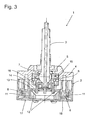
- die Vorrichtung gemäß
Figur 1 um 45° gedreht gegenüber derFigur 2 , im Schnitt, - Figur 4
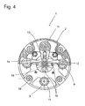
- die Vorrichtung gemäß
Figur 1 in Unteransicht, - Figur 5
- eine Ausführungsvariante der Vorrichtung nach
Figur 1 , mit einem in einem Gehäuse kipp- und drehbar eingesetzten Steuerknüppel, dessen Bewegungen über vier Zwischenglieder an vier in das Gehäuse eingesetzten als Drehpotentiometer ausgebildeten Mitnehmern übertragbar ist, im Schnitt, - Figur 6
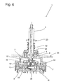
- die Vorrichtung gemäß
Figur 5 mit im Gehäuse zusätzlich vorgesehenen elektrischen Leitungen, im Schnitt und - Figur 7
- die Vorrichtung gemäß
Figur 5 , in Ansicht von unten. -
Figur 1 kann eine Vorrichtung 1 zur Umwandlung von mechanischen Bewegungen eines in einem Gehäuse 2 kippbar und drehbar gelagerten Steuerknüppels 3 entnommen werden. Durch die Bewegungen des Steuerknüppels 3 sollen elektrische Signale erzeugt werden, die zu einer Prozesssteuerung, beispielsweise auf einem Computerbildschirm, dienen und die dem sichtbaren Bewegungsablauf eines Pfeils oder dgl. nachempfunden sind. - Zur Bewegungsausrichtung ist an dem Steuerknüppel 3 in dessen unteren im Gehäuse angeordneten Bereich eine Kugel 7 angeformt, die als Lager für den Steuerknüppel 3 in dem Gehäuse 2 wirkt. Die Kugel 7 des Steuerknüppels 3 wird dabei von zwei Führungsplatten 5 und 6 umgriffen und in diesen drehbar und kippbar gehalten. Die Führungsplatten 5 und 6 sind an dem Gehäuse 2 über Schrauben 19 und Muttern 21 abgestützt.
- Die Führungsplatten 5 und 6 sind nach außen durch eine Abdeckung 4 und ein Abschlussgehäuse 24 verschlossen. Um den Eintritt von Staub und sonstigen Verschmutzungen zu verhindern kann ein nicht dargestellter Faltenbalg auf das Abschlussgehäuse 24 aufgeschoben werden. Der Steuerknüppel 3 durchgreift die Abdeckung 4 und das Abschlussgehäuse 24, so dass dieser von außen manuell greifbar ist. Das Abschlussgehäuse 24 übt dabei eine Rückstellkraft auf den Steuerknüppel 3 aus, durch die dieses in die Ausgangslage überführt ist.
- Des Weiteren ist an dem im Gehäuse 2 endenden unteren Abschnitt des Steuerknüppels 3 ein Teller 15 fest angebracht, von dem vier Stifte 16 abstehen. Das Gehäuse 2 weist vier rund ausgebildete Aufnahmen 10 auf, in die jeweils ein Mitnehmer 11 eingesetzt ist. Die Mitnehmer 11 sind in Richtung einer im Gehäuse 2 untergebrachten Leiterplatte 17 offen ausgebildet und in diesen ist jeweils ein Permanent-Magnet 8 oder 9 derart eingesetzt, dass zwei benachbarte PermanentMagnete 8 oder 9 unterschiedlich gepolt sind, so dass diese ein andersartig ausgebildetes Magnetfeld erzeugen.
- An die Mitnehmer 11 ist jeweils ein als Zwischenglied 12 wirkender Steg 13 angeformt, der in Richtung des Steuerknüppels 3, also in das Zentrum des Gehäuses 2, zugekehrt ist. In den jeweiligen Steg 13 ist ein Langloch 14 eingearbeitet, in das die Stifte 16 des Tellers 15 eingreifen. Somit ist der Steuerknüppel 3 trieblich mit den vier Mitnehmern 11 und damit mit den Permanentmagneten 8 oder 9 verbunden. Die Rotationsachse der Permanentmagnete 8 und 9 verläuft senkrecht zu der von einer Leiterplatte 17 gebildeten horizontalen Ebene.
- Auf der Leiterplatte 17 sind vier Magnetsensoren, die als sogenannte Hall-Sensoren 18 aufgebaut sind, angebracht. Die Position der jeweiligen Hall-Sensoren 18 ist dem jeweiligen Permanentmagnet 8 oder 9 zugeordnet, so dass die Permanentmagnete 8 oder 9 unmittelbar oberhalb und fluchtend zu den Hall-Sensoren 18 verlaufen.
- Den
Figuren 2 bis 4 kann entnommen werden, dass bei einer Bewegung des Steuerknüppels 3 in einer Ebene, die Mitnehmer 11 über die Zwischenglieder 12 im Gehäuse 2 in ihrer Position verändert werden, denn die Mitnehmer 11 sind drehbar im Gehäuse 2 gelagert, so dass durch eine Kippbewegung und/oder eine Verdrehung des Steuerknüppels 3 eine Lageveränderung der jeweiligen Mitnehmer 11 erzeugt wird. Durch die Rotation und der damit verbundenen Winkelveränderung der Mitnehmer 11 gegenüber den Sensoren 18 wird jedoch auch das von den Permanentmagneten 8 oder 9 erzeugte Magnetfeld unmittelbar im Bereich der Hall-Sensoren 18 verändert. Die Hall-Sensoren 18 messen demnach die Magnetfeldänderungen und geben diese an eine elektrische Auswerteeinrichtung, die der Leiterplatte 17 zugeordnet ist, beispielsweise einem Mikroprozessor oder einer andersartig aufgebauten Recheneinheit, weiter. Durch diese Recheneinheiten können die magnetischen Signale der Hall-Sensoren 18 derart in elektrische Signale umgewandelt werden, dass mittels diesen eine Bewegung eines Pfeils auf einem Bildschirm erkennbar ist, oder dass bestimmte Eingabebefehle durch den Steuerknüppel 3 übertragen und weitergeleitet werden. - Des Weiteren ist ersichtlich, dass in dem Gehäuse 2 eine Trennplatte 34 eingesetzt ist, durch die die Mitnehmer 11 in dem Gehäuse 2 abgestützt werden.
- In
Figur 4 ist gezeigt, dass die vier Stifte 16 in dem jeweiligen Langloch 14 der Stege 13 bewegbar eingesetzt sind, so dass durch die Bewegung des Steuerknüppels 3 die jeweiligen Stifte 16 in den Langlöchern 14 verfahren werden und dadurch eine Drehbewegung der Mitnehmer 11 und demnach der Permanentmagnete 8 oder 9 entsteht. Es ist denkbar, lediglich zwei Permanentmagnete 8 oder 9 in jeweils zwei Mitnehmer 11 unterzubringen. Das zusätzliche Paar von Permanentmagneten 8 oder 9 dient entweder der Betriebssicherheit, wenn das erste Paar von Permanentmagneten 8 und 9 ausfällt oder zu zusätzlichen Messungen von Rotationsbewegungen. Durch die Drehung und/oder Kippung des Steuerknüppels 3 werden nämlich die von vier Mitnehmern 11 im gleichen Drehsinn bewegt; dies wird von der Rechen- und Auswerteeinheit erkannt und in entsprechende elektrische Signale umgewandelt.
Wird der Steuerknüppel 3 zusätzlich oder ausschließlich gekippt, bewegen sich jeweils die der Kippbewegung gegenüberliegende Mitnehmer 11 in entgegensetzter Drehrichtung zueinander. - Den
Figuren 5 bis 7 kann entnommen werden, dass an dem im Gehäuse 2 untergebrachten freien Ende des Steuerknüppels 3 der Teller 15' fest angebracht ist, in dem nunmehr vier Führungsnuten 33 eingearbeitet sind. An den jeweiligen Mitnehmern 11 sind Zapfen 31 angeformt, deren freien Ende dem Steuerknüppel 3 zugekehrt sind, also in das Zentrum des Gehäuses 2 ragen. Die freien Enden der Zapfen 31 sind als Kugelkopf 32 ausgebildet und in die jeweilige Führungsnut 33 eingesetzt. Die jeweiligen Kugelköpfe 32 können in der Führungsnut 33 längsverschieblich bewegt werden, so dass die mechanische Übertragung der Bewegungsrichtung des Steuerknüppels 3 auf die Mitnehmer 11 gewährleistet ist. - Die Breite der Führungsnuten 33 entspricht dem Durchmesser der darin eingesetzten Kugelköpfe 32.
- Zusätzlich sind im Inneren des Steuerknüppels 3 mehrere elektrische Leitungen 36 vorgesehen, die mit einem am freien nach außen abstehenden Ende des Steuerknüppels 3 angebrachten Drehknopf oder Taster verbunden sind. Die durch die Drehung des Drehknopfes oder durch die Betätigung des Tasters erzeugten elektrischen Signale werden an die Leiterplatte 17 durch die Leitungen 36 übertragen und von einer auf der Leiterplatte 17 angebrachten elektrischen Recheneinheit verwerket und in elektrische Signale umgewandelt. Der Austritt der elektrischen Leitungen 36 aus dem Steuerknüppel 3 erfolgt unmittelbar im Inneren des Gehäuses 2 und in geringem Abstand zu der Kippebene 35 des Steuerknüppels 3, so dass die elektrischen Leitungen 36 vorteilhafterweise keinen großen Auslenkbewegungen ausgesetzt sind und daher wenig mechanisch belastet werden.
- Ferner können über die Leitungen 36 im Steuerknüppel 3 befindlichen Leuchtdioden angesteuert werden.
- Die Rückstellung des Steuerknüppels 3 in eine Ausgangslage erfolgt durch eine am Abschlussgehäuse 24 aufgesetzte Feder 22, die zwischen dem Abschlussgehäuse 24 und ein am Steuerknüppel 3 angebrachter Anschlag 23 eingesetzt ist. Sobald der Steuerknüppel 3 daher in eine bestimmte Winkellage gekippt oder gedreht wird, entsteht eine Kraft, die auf die Feder 22 einwirkt und die durch diese zusammengepresst wird. Sobald der Steuerknüppel 3 daher wieder keiner Auslenkkraft unterworfen wird, schnappt die Feder 22 in ihre Ursprungslage zurück und richtet den Steuerknüppel 3 senkrecht zu dem Gehäuse 2 verlaufend aus. Dies entspricht der Ausgangslage des Steuerknüppels 3 in Bezug auf das Gehäuse 2.
- In dem Gehäuse 2 können auch mehrere Steuerknüppel 3 vorgesehen sein. Die Hall-Sensoren 18 oder Empfangssensoren sind dann auf der einen Leiterplatte 17 angeordnet, so dass eine solche Ausbildung weniger Platz benötigt und einfach herzustellen ist.
- Des weiteren können die Zwischenglieder (12) derart zusammenwirken, dass eine Über-oder Untersetzung der Bewegung des Steuerknüppels erfolgt.
Claims (6)
- Vorrichtung (1) zur Umwandlung mechanischer Bewegungen in elektrische Signale, die zur Prozesssteuerung dienen,- mit einem Gehäuse (2), in dem ein Steuerknüppel (3) zur Aufnahme und Übertragung der Bewegungen in einer Ebene kippbar angeordnet ist,- mit mindestens zwei dem Steuerknüppel (3) zugeordneten Signalgebern (8, 9), die mittels Zwischenglieder (12) der Vorrichtungs (1) trieblich mit dem Steuerknüppel (3) verbunden sind, und durch die ein Feld in der Bewegungs-Ebene des Steuerknüppels (3) erzeugbar ist,- mit mindestens zwei mit den Signalgebern (8, 9) jeweils zusammen wirkenden Empfangssensoren (18), die unmittelbar im Bereich der Signalgeber (8, 9) in dem Gehäuse (2) untergebracht sind und durch die die Änderung des Feldes messbar ist,- mit jeweils einem fest an die Signalgeber (8, 9) verbundenen Mitnehmer (11), der jeweils in kraftschlüssiger Wirkverbindung mit dem Steuerknüppel (3) steht,- wobei die Zwischenglieder (12) als Zapfen (31) ausgebildet sind, die an jeweils einem der Mitnehmer (11) angeformt sind und die in Richtung des Steuerknüppels (3) weisen, wobeijeder der Signalgeber (8, 9) drehbar in dem Gehäuse (2) gelagert ist,
wobei die Signalgeber (8, 9) als Permanentmagnete (8, 9) ausgebildet sind, durch die ein Magnet-Feld erzeugbar ist, wobei die Empfangssensoren (18) als Hallsensoren ausgebildet sind, wobei mittels der trieblichen Wirkverbindung zwischen dem Steuerknüppel (3) und den Signalgebern (8, 9) eine Drehbewegung und/oder eine Kippbewegung des Steuerknüppels (3) in eine Rotationsbewegung der Signalgeber (8, 9) zu deren Positionsveränderung gegenüber den Empfangssensoren (18) übertragbar ist, wobei die freien Enden der Zapfen (31) jeweils in einer Führungsnut (33) eingesetzt sind, die jeweils in einen mit dem Steuerknüppel (3) fest verbundenen Teller (15) eingearbeitet sind, wobei die in den Führungsnuten (33) angeordneten freien Enden der Zapfen (31) als Kugelkopf (32) ausgebildet sind und wobei die Breite der jeweiligen Führungsnut (33) mit dem Durchmesser des jeweiligen Kugelkopfes (32) korrespondiert. - Vorrichtung nach Anspruch 1,
dadurch gekennzeichnet,
dass mindestens eines der Zwischenglieder (12) als Über- oder Untersetzungsglied ausgebildet ist, durch das die Bewegungen des Steuerknüppels (3) erhöht bzw. verringert sind. - Vorrichtung nach einem oder mehreren der vorgenannten Ansprüche
dadurch gekennzeichnet,
dass die Rotationsachsen der Signalgeber (8, 9) senkrecht zu einer, vorzugsweise horizontalen, Ebene verlaufen, - Vorrichtung nach einem oder mehreren der vorgenannten Ansprüche,
dadurch gekennzeichnet,
dass der Steuerknüppel (3) im Gehäuse (2) drehbar gelagert ist und dass die Drehbewegungen des Steuerknüppels (3) durch die Zwischenglieder (12) auf die Mitnehmer (11) übertragbar sind. - Vorrichtung nach einem oder mehreren der vorgenannten Ansprüche,
dadurch gekennzeichnet,
dass in dem Gehäuse (2) eine Leiterplatte (17) benachbart zu den Signalgeber (8, 9) angeordnet ist, auf der die Empfangssensoren (18) vorgesehen sind und durch die die Änderungen des Feldes in elektrische Signale zur Prozesssteuerung umwandelbar sind. - Vorrichtung nach einem oder mehreren der vorgenannten Ansprüche,
dadurch gekennzeichnet,
dass in das Gehäuse (2) eine Trennplatte (34) eingesetzt ist, in der die Signalgeber (8, 9) abgestützt gehalten sind.
Applications Claiming Priority (1)
| Application Number | Priority Date | Filing Date | Title |
|---|---|---|---|
| DE200610030319 DE102006030319A1 (de) | 2006-06-30 | 2006-06-30 | Vorrichtung zur Umwandlung mechanischer Bewegungen in elektrische Signale |
Publications (2)
| Publication Number | Publication Date |
|---|---|
| EP1903418A1 EP1903418A1 (de) | 2008-03-26 |
| EP1903418B1 true EP1903418B1 (de) | 2014-07-02 |
Family
ID=38565597
Family Applications (1)
| Application Number | Title | Priority Date | Filing Date |
|---|---|---|---|
| EP07011747.8A Not-in-force EP1903418B1 (de) | 2006-06-30 | 2007-06-15 | Vorrichtung zur Umwandlung mechanischer Bewegungen in elektrische Signale |
Country Status (2)
| Country | Link |
|---|---|
| EP (1) | EP1903418B1 (de) |
| DE (1) | DE102006030319A1 (de) |
Cited By (1)
| Publication number | Priority date | Publication date | Assignee | Title |
|---|---|---|---|---|
| EP3367205A1 (de) | 2017-02-24 | 2018-08-29 | RAFI GmbH & Co. KG | Steuer-vorrichtung |
Families Citing this family (5)
| Publication number | Priority date | Publication date | Assignee | Title |
|---|---|---|---|---|
| DE102008037080A1 (de) * | 2008-08-08 | 2010-02-11 | Ford Global Technologies, LLC, Dearborn | Bedieneinrichtung zum Erzeugen von elektrischen Steuersignalen |
| GB2484452B (en) | 2010-07-27 | 2014-12-31 | Penny & Giles Controls Ltd | A control device |
| DE202012006199U1 (de) * | 2012-06-26 | 2013-09-30 | Hatox Gmbh | Joystick |
| CN110475468B (zh) | 2018-03-28 | 2022-07-26 | 南京泉峰科技有限公司 | 骑乘式割草机及其操作装置 |
| CN110313296B (zh) * | 2018-03-28 | 2022-01-04 | 南京德朔实业有限公司 | 骑乘式割草机的操作装置以及骑乘式割草机 |
Citations (2)
| Publication number | Priority date | Publication date | Assignee | Title |
|---|---|---|---|---|
| US4459578A (en) * | 1983-01-13 | 1984-07-10 | Atari, Inc. | Finger control joystick utilizing Hall effect |
| EP0872957A1 (de) * | 1997-04-18 | 1998-10-21 | Eaton Corporation | Schalternanordnung |
Family Cites Families (12)
| Publication number | Priority date | Publication date | Assignee | Title |
|---|---|---|---|---|
| US3392596A (en) * | 1966-05-02 | 1968-07-16 | Bausch & Lomb | Joy stick type multi-operation control device |
| JPS5224990B2 (de) * | 1971-10-30 | 1977-07-05 | ||
| US3942148A (en) | 1974-05-29 | 1976-03-02 | Matsushita Electric Industrial Company, Limited | Device for simultaneously controlling a plurality of variable resistors |
| US4275611A (en) * | 1979-03-29 | 1981-06-30 | Atari, Inc. | Joystick controller |
| US4469330A (en) * | 1982-01-07 | 1984-09-04 | Atari, Inc. | Controller unit for video game |
| WO1991011817A1 (fr) * | 1990-01-31 | 1991-08-08 | Kabushiki Kaisha Komatsu Seisakusho | Dispositif detecteur d'inclinaison pour levier de commande |
| US5675359A (en) * | 1995-01-13 | 1997-10-07 | Advanced Technology Systems, Inc. | Joystick controller |
| US6404417B1 (en) * | 1999-03-22 | 2002-06-11 | Logitech Europe S.A. | Direct drive rotational sensor adapted to withstand off-axis loading |
| US6222179B1 (en) * | 1999-06-10 | 2001-04-24 | Peter J. Mikan | Fiber optic control having joystick |
| GB0006350D0 (en) * | 2000-03-17 | 2000-05-03 | Penny & Giles Controls Ltd | Joystick controller |
| US6329647B1 (en) * | 2000-07-03 | 2001-12-11 | Peter J. Mikan | Compensation reference circuit for opto-mechanical joystick |
| JP3897547B2 (ja) * | 2001-07-05 | 2007-03-28 | アルプス電気株式会社 | 入力装置 |
-
2006
- 2006-06-30 DE DE200610030319 patent/DE102006030319A1/de not_active Ceased
-
2007
- 2007-06-15 EP EP07011747.8A patent/EP1903418B1/de not_active Not-in-force
Patent Citations (2)
| Publication number | Priority date | Publication date | Assignee | Title |
|---|---|---|---|---|
| US4459578A (en) * | 1983-01-13 | 1984-07-10 | Atari, Inc. | Finger control joystick utilizing Hall effect |
| EP0872957A1 (de) * | 1997-04-18 | 1998-10-21 | Eaton Corporation | Schalternanordnung |
Cited By (1)
| Publication number | Priority date | Publication date | Assignee | Title |
|---|---|---|---|---|
| EP3367205A1 (de) | 2017-02-24 | 2018-08-29 | RAFI GmbH & Co. KG | Steuer-vorrichtung |
Also Published As
| Publication number | Publication date |
|---|---|
| EP1903418A1 (de) | 2008-03-26 |
| DE102006030319A1 (de) | 2008-01-03 |
Similar Documents
| Publication | Publication Date | Title |
|---|---|---|
| EP2171315B1 (de) | Elektromechanische gebereinrichtung | |
| EP2761385B1 (de) | Dreh-/drück-bedienvorrichtung für ein mensch-maschine-interface | |
| EP2457002B1 (de) | Vorrichtung zum erfassen der position eines schalt- und/oder wählhebels für ein getriebe und schaltvorrichtung für das getriebe eines kraftfahrzeuges | |
| DE102011005370B4 (de) | Hebelbetätigungsvorrichtung | |
| EP2246668B1 (de) | Elektrischer Stellantrieb | |
| DE102016121671B3 (de) | Positionssensor und Stellgerät mit Positionssensor | |
| DE602004011544T2 (de) | Motorisierter und orientierbarer Messkopf | |
| WO1999010615A1 (de) | Kraftfahrzeug-schliessvorrichtung mit einer positionserkennung eines sich bewegenden stellelementes | |
| EP2771755B1 (de) | Bedienelement mit magnetischer rückstellung | |
| WO2010060527A1 (de) | Anzeigeeinrichtung für einen stellantrieb und stellantrieb für eine armatur | |
| EP1992845B1 (de) | Elektronisches Wählhebelmodul | |
| EP3074836A2 (de) | Stellglied, insbesondere für ein kraftfahrzeug | |
| EP1903418A1 (de) | Vorrichtung zur Umwandlung mechanischer Bewegungen in elektrische Signale | |
| EP3308056A1 (de) | Vorrichtung zur erfassung der position eines fahrstufenwählhebels, kraftfahrzeug | |
| WO2009040012A1 (de) | Bedieneinrichtung für den fokussiertrieb eines mikroskops | |
| DE102007026303A1 (de) | Wählhebelmodul mit 3D-Magnetsensorelement | |
| EP2160527B1 (de) | Vorrichtung zum erfassen von schaltstellungen | |
| EP3320305A1 (de) | Sensoranordnung mit modularem aufbau | |
| WO2014000864A1 (de) | Joystick | |
| DE102006030746A1 (de) | Hebelschalter für einen Lenkstock eines Kraftfahrzeugs | |
| EP3064793A1 (de) | Bewegungssensorsystem für Schienenfahrzeuge | |
| DE102015208803B3 (de) | Dreheinheit für ein Koordinatenmessgerät | |
| DE102011005372A1 (de) | Hebelbetätigungsvorrichtung | |
| DE102014208025B4 (de) | Vorrichtung zur Einstellung eines Betriebsparameters einer elektrischen Einrichtung | |
| DE202009003485U1 (de) | Joystick |
Legal Events
| Date | Code | Title | Description |
|---|---|---|---|
| PUAI | Public reference made under article 153(3) epc to a published international application that has entered the european phase |
Free format text: ORIGINAL CODE: 0009012 |
|
| AK | Designated contracting states |
Kind code of ref document: A1 Designated state(s): AT BE BG CH CY CZ DE DK EE ES FI FR GB GR HU IE IS IT LI LT LU LV MC MT NL PL PT RO SE SI SK TR |
|
| AX | Request for extension of the european patent |
Extension state: AL BA HR MK YU |
|
| 17P | Request for examination filed |
Effective date: 20080510 |
|
| 17Q | First examination report despatched |
Effective date: 20080623 |
|
| AKX | Designation fees paid |
Designated state(s): AT BE BG CH CY CZ DE DK EE ES FI FR GB GR HU IE IS IT LI LT LU LV MC MT NL PL PT RO SE SI SK TR |
|
| GRAP | Despatch of communication of intention to grant a patent |
Free format text: ORIGINAL CODE: EPIDOSNIGR1 |
|
| INTG | Intention to grant announced |
Effective date: 20140327 |
|
| GRAS | Grant fee paid |
Free format text: ORIGINAL CODE: EPIDOSNIGR3 |
|
| GRAA | (expected) grant |
Free format text: ORIGINAL CODE: 0009210 |
|
| AK | Designated contracting states |
Kind code of ref document: B1 Designated state(s): AT BE BG CH CY CZ DE DK EE ES FI FR GB GR HU IE IS IT LI LT LU LV MC MT NL PL PT RO SE SI SK TR |
|
| REG | Reference to a national code |
Ref country code: GB Ref legal event code: FG4D Free format text: NOT ENGLISH |
|
| REG | Reference to a national code |
Ref country code: AT Ref legal event code: REF Ref document number: 676217 Country of ref document: AT Kind code of ref document: T Effective date: 20140715 Ref country code: CH Ref legal event code: EP |
|
| REG | Reference to a national code |
Ref country code: IE Ref legal event code: FG4D Free format text: LANGUAGE OF EP DOCUMENT: GERMAN |
|
| REG | Reference to a national code |
Ref country code: DE Ref legal event code: R096 Ref document number: 502007013247 Country of ref document: DE Effective date: 20140814 |
|
| REG | Reference to a national code |
Ref country code: NL Ref legal event code: VDEP Effective date: 20140702 |
|
| REG | Reference to a national code |
Ref country code: LT Ref legal event code: MG4D |
|
| PG25 | Lapsed in a contracting state [announced via postgrant information from national office to epo] |
Ref country code: GR Free format text: LAPSE BECAUSE OF FAILURE TO SUBMIT A TRANSLATION OF THE DESCRIPTION OR TO PAY THE FEE WITHIN THE PRESCRIBED TIME-LIMIT Effective date: 20141003 Ref country code: SE Free format text: LAPSE BECAUSE OF FAILURE TO SUBMIT A TRANSLATION OF THE DESCRIPTION OR TO PAY THE FEE WITHIN THE PRESCRIBED TIME-LIMIT Effective date: 20140702 Ref country code: PT Free format text: LAPSE BECAUSE OF FAILURE TO SUBMIT A TRANSLATION OF THE DESCRIPTION OR TO PAY THE FEE WITHIN THE PRESCRIBED TIME-LIMIT Effective date: 20141103 Ref country code: ES Free format text: LAPSE BECAUSE OF FAILURE TO SUBMIT A TRANSLATION OF THE DESCRIPTION OR TO PAY THE FEE WITHIN THE PRESCRIBED TIME-LIMIT Effective date: 20140702 Ref country code: CZ Free format text: LAPSE BECAUSE OF FAILURE TO SUBMIT A TRANSLATION OF THE DESCRIPTION OR TO PAY THE FEE WITHIN THE PRESCRIBED TIME-LIMIT Effective date: 20140702 Ref country code: LT Free format text: LAPSE BECAUSE OF FAILURE TO SUBMIT A TRANSLATION OF THE DESCRIPTION OR TO PAY THE FEE WITHIN THE PRESCRIBED TIME-LIMIT Effective date: 20140702 Ref country code: FI Free format text: LAPSE BECAUSE OF FAILURE TO SUBMIT A TRANSLATION OF THE DESCRIPTION OR TO PAY THE FEE WITHIN THE PRESCRIBED TIME-LIMIT Effective date: 20140702 Ref country code: BG Free format text: LAPSE BECAUSE OF FAILURE TO SUBMIT A TRANSLATION OF THE DESCRIPTION OR TO PAY THE FEE WITHIN THE PRESCRIBED TIME-LIMIT Effective date: 20141002 |
|
| PG25 | Lapsed in a contracting state [announced via postgrant information from national office to epo] |
Ref country code: PL Free format text: LAPSE BECAUSE OF FAILURE TO SUBMIT A TRANSLATION OF THE DESCRIPTION OR TO PAY THE FEE WITHIN THE PRESCRIBED TIME-LIMIT Effective date: 20140702 Ref country code: CY Free format text: LAPSE BECAUSE OF FAILURE TO SUBMIT A TRANSLATION OF THE DESCRIPTION OR TO PAY THE FEE WITHIN THE PRESCRIBED TIME-LIMIT Effective date: 20140702 Ref country code: IS Free format text: LAPSE BECAUSE OF FAILURE TO SUBMIT A TRANSLATION OF THE DESCRIPTION OR TO PAY THE FEE WITHIN THE PRESCRIBED TIME-LIMIT Effective date: 20141102 Ref country code: LV Free format text: LAPSE BECAUSE OF FAILURE TO SUBMIT A TRANSLATION OF THE DESCRIPTION OR TO PAY THE FEE WITHIN THE PRESCRIBED TIME-LIMIT Effective date: 20140702 Ref country code: NL Free format text: LAPSE BECAUSE OF FAILURE TO SUBMIT A TRANSLATION OF THE DESCRIPTION OR TO PAY THE FEE WITHIN THE PRESCRIBED TIME-LIMIT Effective date: 20140702 |
|
| REG | Reference to a national code |
Ref country code: DE Ref legal event code: R097 Ref document number: 502007013247 Country of ref document: DE |
|
| PG25 | Lapsed in a contracting state [announced via postgrant information from national office to epo] |
Ref country code: RO Free format text: LAPSE BECAUSE OF FAILURE TO SUBMIT A TRANSLATION OF THE DESCRIPTION OR TO PAY THE FEE WITHIN THE PRESCRIBED TIME-LIMIT Effective date: 20140702 Ref country code: EE Free format text: LAPSE BECAUSE OF FAILURE TO SUBMIT A TRANSLATION OF THE DESCRIPTION OR TO PAY THE FEE WITHIN THE PRESCRIBED TIME-LIMIT Effective date: 20140702 Ref country code: IT Free format text: LAPSE BECAUSE OF FAILURE TO SUBMIT A TRANSLATION OF THE DESCRIPTION OR TO PAY THE FEE WITHIN THE PRESCRIBED TIME-LIMIT Effective date: 20140702 Ref country code: SK Free format text: LAPSE BECAUSE OF FAILURE TO SUBMIT A TRANSLATION OF THE DESCRIPTION OR TO PAY THE FEE WITHIN THE PRESCRIBED TIME-LIMIT Effective date: 20140702 Ref country code: DK Free format text: LAPSE BECAUSE OF FAILURE TO SUBMIT A TRANSLATION OF THE DESCRIPTION OR TO PAY THE FEE WITHIN THE PRESCRIBED TIME-LIMIT Effective date: 20140702 |
|
| PLBE | No opposition filed within time limit |
Free format text: ORIGINAL CODE: 0009261 |
|
| STAA | Information on the status of an ep patent application or granted ep patent |
Free format text: STATUS: NO OPPOSITION FILED WITHIN TIME LIMIT |
|
| 26N | No opposition filed |
Effective date: 20150407 |
|
| PG25 | Lapsed in a contracting state [announced via postgrant information from national office to epo] |
Ref country code: SI Free format text: LAPSE BECAUSE OF FAILURE TO SUBMIT A TRANSLATION OF THE DESCRIPTION OR TO PAY THE FEE WITHIN THE PRESCRIBED TIME-LIMIT Effective date: 20140702 |
|
| PG25 | Lapsed in a contracting state [announced via postgrant information from national office to epo] |
Ref country code: MC Free format text: LAPSE BECAUSE OF FAILURE TO SUBMIT A TRANSLATION OF THE DESCRIPTION OR TO PAY THE FEE WITHIN THE PRESCRIBED TIME-LIMIT Effective date: 20140702 |
|
| REG | Reference to a national code |
Ref country code: CH Ref legal event code: PL |
|
| GBPC | Gb: european patent ceased through non-payment of renewal fee |
Effective date: 20150615 |
|
| PG25 | Lapsed in a contracting state [announced via postgrant information from national office to epo] |
Ref country code: LU Free format text: LAPSE BECAUSE OF FAILURE TO SUBMIT A TRANSLATION OF THE DESCRIPTION OR TO PAY THE FEE WITHIN THE PRESCRIBED TIME-LIMIT Effective date: 20150615 |
|
| REG | Reference to a national code |
Ref country code: IE Ref legal event code: MM4A |
|
| REG | Reference to a national code |
Ref country code: FR Ref legal event code: ST Effective date: 20160229 |
|
| PG25 | Lapsed in a contracting state [announced via postgrant information from national office to epo] |
Ref country code: LI Free format text: LAPSE BECAUSE OF NON-PAYMENT OF DUE FEES Effective date: 20150630 Ref country code: IE Free format text: LAPSE BECAUSE OF NON-PAYMENT OF DUE FEES Effective date: 20150615 Ref country code: GB Free format text: LAPSE BECAUSE OF NON-PAYMENT OF DUE FEES Effective date: 20150615 Ref country code: CH Free format text: LAPSE BECAUSE OF NON-PAYMENT OF DUE FEES Effective date: 20150630 |
|
| PG25 | Lapsed in a contracting state [announced via postgrant information from national office to epo] |
Ref country code: FR Free format text: LAPSE BECAUSE OF NON-PAYMENT OF DUE FEES Effective date: 20150630 |
|
| REG | Reference to a national code |
Ref country code: AT Ref legal event code: MM01 Ref document number: 676217 Country of ref document: AT Kind code of ref document: T Effective date: 20150615 |
|
| PG25 | Lapsed in a contracting state [announced via postgrant information from national office to epo] |
Ref country code: AT Free format text: LAPSE BECAUSE OF NON-PAYMENT OF DUE FEES Effective date: 20150615 |
|
| PG25 | Lapsed in a contracting state [announced via postgrant information from national office to epo] |
Ref country code: MT Free format text: LAPSE BECAUSE OF FAILURE TO SUBMIT A TRANSLATION OF THE DESCRIPTION OR TO PAY THE FEE WITHIN THE PRESCRIBED TIME-LIMIT Effective date: 20140702 |
|
| PG25 | Lapsed in a contracting state [announced via postgrant information from national office to epo] |
Ref country code: HU Free format text: LAPSE BECAUSE OF FAILURE TO SUBMIT A TRANSLATION OF THE DESCRIPTION OR TO PAY THE FEE WITHIN THE PRESCRIBED TIME-LIMIT; INVALID AB INITIO Effective date: 20070615 |
|
| PG25 | Lapsed in a contracting state [announced via postgrant information from national office to epo] |
Ref country code: BE Free format text: LAPSE BECAUSE OF NON-PAYMENT OF DUE FEES Effective date: 20150630 |
|
| PG25 | Lapsed in a contracting state [announced via postgrant information from national office to epo] |
Ref country code: TR Free format text: LAPSE BECAUSE OF FAILURE TO SUBMIT A TRANSLATION OF THE DESCRIPTION OR TO PAY THE FEE WITHIN THE PRESCRIBED TIME-LIMIT Effective date: 20140702 |
|
| REG | Reference to a national code |
Ref country code: DE Ref legal event code: R082 Ref document number: 502007013247 Country of ref document: DE Representative=s name: GEITZ PATENTANWAELTE PARTG MBB, DE Ref country code: DE Ref legal event code: R082 Ref document number: 502007013247 Country of ref document: DE Representative=s name: GEITZ TRUCKENMUELLER LUCHT CHRIST PATENTANWAEL, DE |
|
| P01 | Opt-out of the competence of the unified patent court (upc) registered |
Effective date: 20230513 |
|
| PGFP | Annual fee paid to national office [announced via postgrant information from national office to epo] |
Ref country code: DE Payment date: 20240617 Year of fee payment: 18 |
|
| REG | Reference to a national code |
Ref country code: DE Ref legal event code: R119 Ref document number: 502007013247 Country of ref document: DE |
|
| PG25 | Lapsed in a contracting state [announced via postgrant information from national office to epo] |
Ref country code: DE Free format text: LAPSE BECAUSE OF NON-PAYMENT OF DUE FEES Effective date: 20260101 |