EP1903418B1 - Dispositif destiné à la transformation de mouvements mécaniques en signaux électriques - Google Patents
Dispositif destiné à la transformation de mouvements mécaniques en signaux électriques Download PDFInfo
- Publication number
- EP1903418B1 EP1903418B1 EP07011747.8A EP07011747A EP1903418B1 EP 1903418 B1 EP1903418 B1 EP 1903418B1 EP 07011747 A EP07011747 A EP 07011747A EP 1903418 B1 EP1903418 B1 EP 1903418B1
- Authority
- EP
- European Patent Office
- Prior art keywords
- control stick
- housing
- signal transmitters
- case
- joystick
- Prior art date
- Legal status (The legal status is an assumption and is not a legal conclusion. Google has not performed a legal analysis and makes no representation as to the accuracy of the status listed.)
- Active
Links
Images


Classifications
-
- G—PHYSICS
- G05—CONTROLLING; REGULATING
- G05G—CONTROL DEVICES OR SYSTEMS INSOFAR AS CHARACTERISED BY MECHANICAL FEATURES ONLY
- G05G9/00—Manually-actuated control mechanisms provided with one single controlling member co-operating with two or more controlled members, e.g. selectively, simultaneously
- G05G9/02—Manually-actuated control mechanisms provided with one single controlling member co-operating with two or more controlled members, e.g. selectively, simultaneously the controlling member being movable in different independent ways, movement in each individual way actuating one controlled member only
- G05G9/04—Manually-actuated control mechanisms provided with one single controlling member co-operating with two or more controlled members, e.g. selectively, simultaneously the controlling member being movable in different independent ways, movement in each individual way actuating one controlled member only in which movement in two or more ways can occur simultaneously
- G05G9/047—Manually-actuated control mechanisms provided with one single controlling member co-operating with two or more controlled members, e.g. selectively, simultaneously the controlling member being movable in different independent ways, movement in each individual way actuating one controlled member only in which movement in two or more ways can occur simultaneously the controlling member being movable by hand about orthogonal axes, e.g. joysticks
-
- G—PHYSICS
- G05—CONTROLLING; REGULATING
- G05G—CONTROL DEVICES OR SYSTEMS INSOFAR AS CHARACTERISED BY MECHANICAL FEATURES ONLY
- G05G7/00—Manually-actuated control mechanisms provided with one single controlling member co-operating with one single controlled member; Details thereof
- G05G7/02—Manually-actuated control mechanisms provided with one single controlling member co-operating with one single controlled member; Details thereof characterised by special provisions for conveying or converting motion, or for acting at a distance
-
- G—PHYSICS
- G05—CONTROLLING; REGULATING
- G05G—CONTROL DEVICES OR SYSTEMS INSOFAR AS CHARACTERISED BY MECHANICAL FEATURES ONLY
- G05G9/00—Manually-actuated control mechanisms provided with one single controlling member co-operating with two or more controlled members, e.g. selectively, simultaneously
- G05G9/02—Manually-actuated control mechanisms provided with one single controlling member co-operating with two or more controlled members, e.g. selectively, simultaneously the controlling member being movable in different independent ways, movement in each individual way actuating one controlled member only
- G05G9/04—Manually-actuated control mechanisms provided with one single controlling member co-operating with two or more controlled members, e.g. selectively, simultaneously the controlling member being movable in different independent ways, movement in each individual way actuating one controlled member only in which movement in two or more ways can occur simultaneously
- G05G9/047—Manually-actuated control mechanisms provided with one single controlling member co-operating with two or more controlled members, e.g. selectively, simultaneously the controlling member being movable in different independent ways, movement in each individual way actuating one controlled member only in which movement in two or more ways can occur simultaneously the controlling member being movable by hand about orthogonal axes, e.g. joysticks
- G05G2009/0474—Manually-actuated control mechanisms provided with one single controlling member co-operating with two or more controlled members, e.g. selectively, simultaneously the controlling member being movable in different independent ways, movement in each individual way actuating one controlled member only in which movement in two or more ways can occur simultaneously the controlling member being movable by hand about orthogonal axes, e.g. joysticks characterised by means converting mechanical movement into electric signals
- G05G2009/04748—Position sensor for rotary movement, e.g. potentiometer
-
- G—PHYSICS
- G05—CONTROLLING; REGULATING
- G05G—CONTROL DEVICES OR SYSTEMS INSOFAR AS CHARACTERISED BY MECHANICAL FEATURES ONLY
- G05G9/00—Manually-actuated control mechanisms provided with one single controlling member co-operating with two or more controlled members, e.g. selectively, simultaneously
- G05G9/02—Manually-actuated control mechanisms provided with one single controlling member co-operating with two or more controlled members, e.g. selectively, simultaneously the controlling member being movable in different independent ways, movement in each individual way actuating one controlled member only
- G05G9/04—Manually-actuated control mechanisms provided with one single controlling member co-operating with two or more controlled members, e.g. selectively, simultaneously the controlling member being movable in different independent ways, movement in each individual way actuating one controlled member only in which movement in two or more ways can occur simultaneously
- G05G9/047—Manually-actuated control mechanisms provided with one single controlling member co-operating with two or more controlled members, e.g. selectively, simultaneously the controlling member being movable in different independent ways, movement in each individual way actuating one controlled member only in which movement in two or more ways can occur simultaneously the controlling member being movable by hand about orthogonal axes, e.g. joysticks
- G05G2009/0474—Manually-actuated control mechanisms provided with one single controlling member co-operating with two or more controlled members, e.g. selectively, simultaneously the controlling member being movable in different independent ways, movement in each individual way actuating one controlled member only in which movement in two or more ways can occur simultaneously the controlling member being movable by hand about orthogonal axes, e.g. joysticks characterised by means converting mechanical movement into electric signals
- G05G2009/04755—Magnetic sensor, e.g. hall generator, pick-up coil
-
- G—PHYSICS
- G05—CONTROLLING; REGULATING
- G05G—CONTROL DEVICES OR SYSTEMS INSOFAR AS CHARACTERISED BY MECHANICAL FEATURES ONLY
- G05G9/00—Manually-actuated control mechanisms provided with one single controlling member co-operating with two or more controlled members, e.g. selectively, simultaneously
- G05G9/02—Manually-actuated control mechanisms provided with one single controlling member co-operating with two or more controlled members, e.g. selectively, simultaneously the controlling member being movable in different independent ways, movement in each individual way actuating one controlled member only
- G05G9/04—Manually-actuated control mechanisms provided with one single controlling member co-operating with two or more controlled members, e.g. selectively, simultaneously the controlling member being movable in different independent ways, movement in each individual way actuating one controlled member only in which movement in two or more ways can occur simultaneously
- G05G9/047—Manually-actuated control mechanisms provided with one single controlling member co-operating with two or more controlled members, e.g. selectively, simultaneously the controlling member being movable in different independent ways, movement in each individual way actuating one controlled member only in which movement in two or more ways can occur simultaneously the controlling member being movable by hand about orthogonal axes, e.g. joysticks
- G05G2009/0474—Manually-actuated control mechanisms provided with one single controlling member co-operating with two or more controlled members, e.g. selectively, simultaneously the controlling member being movable in different independent ways, movement in each individual way actuating one controlled member only in which movement in two or more ways can occur simultaneously the controlling member being movable by hand about orthogonal axes, e.g. joysticks characterised by means converting mechanical movement into electric signals
- G05G2009/04759—Light-sensitive detector, e.g. photoelectric
Definitions
- the invention relates to a device for converting mechanical movements into electrical signals, which serve for process control, according to the preamble of claim 1.
- the magnetically conductive sheet terminates in the region of the respective Hall sensor, so that the movements of the pole pieces, so the changes in the magnetic field upon actuation of the joystick, can be determined by this.
- the thus evaluated magnetic signals are then converted into electrical signals, for example by a microprocessor, and passed on to an electrical unit for their litigation.
- the movements of the joystick can first in changes of a magnetic field and then in electrical signal be converted to litigation. Accordingly, by such a joystick device, control signals can be transmitted to a screen or the like.
- the joystick is tiltably mounted in a housing.
- the housing facing the free end of the joystick is drivingly connected to a variety of mechanical components, such as gears, return springs and mounting shoes connected.
- the movements of the joystick are therefore converted into rotational movements of the gears and in length of the return spring.
- These mechanical components are connected to actuators, through which the rotational movement of the gears and the changes in length of the return springs are measurable.
- the mechanical measurement signals generated in this way can be converted into electrical signals which map the movement changes of the joystick and can be used in corresponding electrical devices for their control.
- the arms connected to the control stick can perform relative movements in the area of the Hall sensors when the control stick is tilted. Also by this conversion device rotational movements or superimpositions of tilting and rotational movements are not transferable to the arms on which the magnets are arranged in the Hall sensors, such rotation or overlay movements can not measure.
- the position of each signal generator is precisely defined in the housing and is subject to any changes during a longer period of operation by force or other shocks. Furthermore, the assignment of the signal generator in the region of the mounted on a printed circuit board receiving sensors is exactly vorappelbar, so that the setting of the field changes or the sensor signal is not subject to unwanted fluctuations even with a longer operating time. Namely, since the distance between the signal transmitters, which are fixedly supported on the drivers and the mounted on the circuit board receiving sensors is maintained constant, the distance between these components remains unchanged after assembly, so that by the one-time adjustment and calibration of the device reliable and accurate operation is possible.
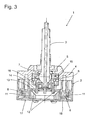
- FIG. 1 For example, a device 1 for converting mechanical movements of a control stick 3 which is tiltable and rotatably mounted in a housing 2 can be taken. By the movements of the joystick 3 electrical signals are to be generated, which serve for a process control, for example on a computer screen, and which are modeled on the visible movement of an arrow or the like.
- a ball 7 is integrally formed on the control stick 3 in the lower region arranged in the housing, which ball acts as a bearing for the control stick 3 in the housing 2.
- the ball 7 of the joystick 3 is thereby encompassed by two guide plates 5 and 6 and held in these rotatable and tiltable.
- the guide plates 5 and 6 are supported on the housing 2 via screws 19 and nuts 21.
- the guide plates 5 and 6 are closed to the outside by a cover 4 and a closure housing 24.
- a bellows not shown, can be pushed onto the closure housing 24.
- the joystick 3 passes through the cover 4 and the end housing 24, so that it is manually accessible from the outside.
- the end housing 24 exerts a restoring force on the control stick 3, by which this is transferred to the starting position.
- a plate 15 is fixedly attached to the ends ending in the housing 2 lower portion of the joystick 3, projecting from the four pins 16.
- the housing 2 has four round recesses 10, in each of which a driver 11 is inserted.
- the carriers 11 are designed to be open in the direction of a printed circuit board 17 accommodated in the housing 2, and in each case a permanent magnet 8 or 9 is inserted in such a way that two adjacent permanent magnets 8 or 9 are poled differently, so that they produce a magnetic field of a different design.
- circuit board 17 On the circuit board 17 are four magnetic sensors, which are constructed as so-called Hall sensors 18, mounted. The position of the respective Hall sensors 18 is associated with the respective permanent magnet 8 or 9, so that the permanent magnets 8 or 9 extend directly above and in alignment with the Hall sensors 18.
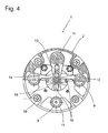
- FIGS. 2 to 4 can be seen that in a movement of the joystick 3 in a plane, the driver 11 are changed over the intermediate members 12 in the housing 2 in position, because the drivers 11 are rotatably mounted in the housing 2, so that by a tilting movement and / or a rotation of the joystick 3 a change in position of the respective driver 11 is generated. Due to the rotation and the associated change in angle of the driver 11 relative to the sensors 18, however, the magnetic field generated by the permanent magnets 8 or 9 is also changed directly in the region of the Hall sensors 18. The Hall sensors 18 thus measure the magnetic field changes and pass them on to an electrical evaluation device, which is assigned to the printed circuit board 17, for example a microprocessor or a differently constructed arithmetic unit.
- the magnetic signals of the Hall sensors 18 can be converted into electrical signals in such a way that a movement of an arrow on a screen can be recognized by means of them, or that specific input commands are transmitted and forwarded by the control stick 3.
- a partition plate 34 is inserted, by which the drivers 11 are supported in the housing 2.
- FIG. 4 It is shown that the four pins 16 are movably inserted in the respective elongated hole 14 of the webs 13, so that the respective pins 16 are moved in the oblong holes 14 by the movement of the control stick 3 and thereby a rotational movement of the driver 11 and thus the permanent magnets. 8 or 9 is created. It is conceivable to accommodate only two permanent magnets 8 or 9 in each case two drivers 11. The additional pair of permanent magnets 8 or 9 serve either operational safety when the first pair of permanent magnets 8 and 9 fail or for additional measurements of rotational movements.
- the rotation and / or tilting of the joystick 3 namely that of four drivers 11 are moved in the same direction of rotation; this is detected by the computing and evaluation and converted into corresponding electrical signals. If the joystick 3 additionally or exclusively tilted, each of the tilting movement opposite carriers 11 move in opposite direction of rotation to each other.
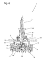
- FIGS. 5 to 7 can be seen that at the housed in the housing 2 free end of the joystick 3, the plate 15 'is fixedly mounted, in which now four guide grooves 33 are incorporated.
- the free end of the control stick 3 are facing, so protrude into the center of the housing 2.
- the free ends of the pins 31 are as Ball head 32 formed and inserted into the respective guide groove 33.
- the respective ball heads 32 can be moved longitudinally displaceably in the guide groove 33, so that the mechanical transmission of the direction of movement of the control stick 3 to the drivers 11 is ensured.
- the width of the guide grooves 33 corresponds to the diameter of the ball heads 32 inserted therein.
- a plurality of electrical lines 36 are provided in the interior of the joystick 3, which are connected to a mounted on the free outwardly projecting end of the joystick control knob 3 or button.
- the electrical signals generated by the rotation of the knob or by the operation of the button are transmitted to the circuit board 17 through the lines 36 and moved from an attached on the circuit board 17 electrical computing unit and converted into electrical signals.
- the exit of the electrical lines 36 from the joystick 3 takes place directly in the interior of the housing 2 and at a small distance to the tilting plane 35 of the joystick 3, so that the electrical lines 36 are advantageously exposed to no large deflecting movements and therefore little mechanical load.
- light-emitting diodes located in the control stick 3 can be actuated via the lines 36.
- the provision of the joystick 3 in a starting position is effected by a patch on the end housing 24 spring 22, which is inserted between the end housing 24 and attached to the control stick 3 stop 23.
- a force which acts on the spring 22 and which is compressed by this arises a force which acts on the spring 22 and which is compressed by this.
- the spring 22 snaps back into its original position and aligns the joystick 3 perpendicular to the housing 2. This corresponds to the starting position of the joystick 3 with respect to the housing 2.
- a plurality of control sticks 3 may be provided in the housing 2, a plurality of control sticks 3 may be provided.
- the Hall sensors 18 or receiving sensors are then arranged on the one circuit board 17, so that such a configuration requires less space and is easy to manufacture.
- intermediate links (12) can cooperate in such a way that an over or under reduction of the movement of the joystick takes place.
Claims (6)
- Dispositif (1) servant à la transformation de mouvements mécaniques en signaux électriques pour la commande de procédés,- comprenant un boîtier (2) dans lequel est logé, de manière basculante dans un plan, un levier de commande (3) pour la saisie et la transmission des mouvements,- avec au moins deux transmetteurs de signaux (8, 9) assignés au levier de commande (3) qui, moyennant des éléments intermédiaires (12) du dispositif (1), sont liés par entraînement avec le levier de commande (3) et qui créent un champ dans le plan de mouvement du levier de commande (3),- avec au moins deux capteurs de réception (18) collaborant respectivement ensemble avec les transmetteurs de signaux (8, 9) qui sont arrangés directement près des transmetteurs de signaux (8, 9) dans le boîtier (2) et qui permettent de mesurer le changement du champ,- avec respectivement un entraîneur (11) raccordé rigidement aux transmetteurs de signaux (8, 9) et lié respectivement de manière entraînée par adhérence avec le levier de commande (3),- où les éléments intermédiaires (12) sont conçus en tant que tétons (31) formés sur respectivement un des entraîneurs (11), et donnant en direction du levier de commande (3), où chacun des transmetteurs de signaux (8, 9) est logé en rotation dans le boîtier (2), où les transmetteurs de signaux (8, 9) sont conçus en tant qu'aimants permanents (8, 9) qui permettent de créer un champ magnétique, où les capteurs de réception (18) sont conçus en tant que capteurs de Hall, où, moyennant la liaison par adhérence entre le levier de commande (3) et les transmetteurs de signaux (8, 9), il se laisser transmettre une rotation et/ou un basculement du levier de commande (3) en une rotation des transmetteurs de signaux (8, 9) en vue de leur déplacement par rapport aux capteurs de réception (18), où les extrémités libres des tétons (31) sont insérées respectivement dans une rainure de guidage (33) pratiquée respectivement dans un plateau (15) rigidement lié au levier de commande (3), où les extrémités libres des tétons (31) disposées dans les rainures de guidage (33) sont conçues en tant que têtes sphériques (32), et où la largeur de la rainure de guidage respective (33) correspond au diamètre de la tête sphérique respective (32).
- Dispositif d'après la revendication 1,
caractérisé en ce que
au moins un des éléments intermédiaires (12) est conçu en tant qu'élément de surmultiplication ou de démultiplication ayant pour fonction d'agrandir ou de réduire les mouvements du levier de commande (3). - Dispositif d'après une ou plusieurs des revendications précédentes,
caractérisé en ce que
les axes de rotation des transmetteurs de signaux (8, 9) sont perpendiculaires à un plan de préférence horizontal. - Dispositif d'après une ou plusieurs des revendications précédentes,
caractérisé en ce que
le levier de commande (3) est logé en rotation dans le boîtier (2) et que les éléments intermédiaires (12) permettent de transmettre les rotations du levier de commande (3) aux entraîneurs (11). - Dispositif d'après une ou plusieurs des revendications précédentes,
caractérisé en ce que
dans le boîtier (2), il est prévu une carte imprimée (17) avoisinant les transmetteurs de signaux (8, 9), sur laquelle sont arrangés les capteurs de réception (18), et qui permet de transformer les changements du champ en signaux électriques pour la commande de procédés. - Dispositif d'après une ou plusieurs des revendications précédentes,
caractérisé en ce que
dans le boîtier (2), il est monté une plaque de séparation (34) dans laquelle sont retenus les transmetteurs de signaux (8, 9).
Applications Claiming Priority (1)
| Application Number | Priority Date | Filing Date | Title |
|---|---|---|---|
| DE200610030319 DE102006030319A1 (de) | 2006-06-30 | 2006-06-30 | Vorrichtung zur Umwandlung mechanischer Bewegungen in elektrische Signale |
Publications (2)
| Publication Number | Publication Date |
|---|---|
| EP1903418A1 EP1903418A1 (fr) | 2008-03-26 |
| EP1903418B1 true EP1903418B1 (fr) | 2014-07-02 |
Family
ID=38565597
Family Applications (1)
| Application Number | Title | Priority Date | Filing Date |
|---|---|---|---|
| EP07011747.8A Active EP1903418B1 (fr) | 2006-06-30 | 2007-06-15 | Dispositif destiné à la transformation de mouvements mécaniques en signaux électriques |
Country Status (2)
| Country | Link |
|---|---|
| EP (1) | EP1903418B1 (fr) |
| DE (1) | DE102006030319A1 (fr) |
Cited By (1)
| Publication number | Priority date | Publication date | Assignee | Title |
|---|---|---|---|---|
| EP3367205A1 (fr) | 2017-02-24 | 2018-08-29 | RAFI GmbH & Co. KG | Dispositif de commande |
Families Citing this family (5)
| Publication number | Priority date | Publication date | Assignee | Title |
|---|---|---|---|---|
| DE102008037080A1 (de) * | 2008-08-08 | 2010-02-11 | Ford Global Technologies, LLC, Dearborn | Bedieneinrichtung zum Erzeugen von elektrischen Steuersignalen |
| GB2484452B (en) | 2010-07-27 | 2014-12-31 | Penny & Giles Controls Ltd | A control device |
| DE202012006199U1 (de) * | 2012-06-26 | 2013-09-30 | Hatox Gmbh | Joystick |
| CN110313297B (zh) * | 2018-03-28 | 2021-03-05 | 南京德朔实业有限公司 | 骑乘式割草机的操作装置以及骑乘式割草机 |
| WO2019184983A1 (fr) | 2018-03-28 | 2019-10-03 | 南京德朔实业有限公司 | Tondeuse à gazon à conducteur porté et son dispositif d'actionnement |
Citations (2)
| Publication number | Priority date | Publication date | Assignee | Title |
|---|---|---|---|---|
| US4459578A (en) * | 1983-01-13 | 1984-07-10 | Atari, Inc. | Finger control joystick utilizing Hall effect |
| EP0872957A1 (fr) * | 1997-04-18 | 1998-10-21 | Eaton Corporation | Dispositif de commutation |
Family Cites Families (12)
| Publication number | Priority date | Publication date | Assignee | Title |
|---|---|---|---|---|
| US3392596A (en) * | 1966-05-02 | 1968-07-16 | Bausch & Lomb | Joy stick type multi-operation control device |
| JPS5224990B2 (fr) * | 1971-10-30 | 1977-07-05 | ||
| US3942148A (en) | 1974-05-29 | 1976-03-02 | Matsushita Electric Industrial Company, Limited | Device for simultaneously controlling a plurality of variable resistors |
| US4275611A (en) * | 1979-03-29 | 1981-06-30 | Atari, Inc. | Joystick controller |
| US4469330A (en) * | 1982-01-07 | 1984-09-04 | Atari, Inc. | Controller unit for video game |
| US5224589A (en) * | 1990-01-31 | 1993-07-06 | Kabushiki Kaisha Komatsu Seisakusho | Operating lever device |
| US5675359A (en) * | 1995-01-13 | 1997-10-07 | Advanced Technology Systems, Inc. | Joystick controller |
| US6404417B1 (en) * | 1999-03-22 | 2002-06-11 | Logitech Europe S.A. | Direct drive rotational sensor adapted to withstand off-axis loading |
| US6222179B1 (en) * | 1999-06-10 | 2001-04-24 | Peter J. Mikan | Fiber optic control having joystick |
| GB0006350D0 (en) * | 2000-03-17 | 2000-05-03 | Penny & Giles Controls Ltd | Joystick controller |
| US6329647B1 (en) * | 2000-07-03 | 2001-12-11 | Peter J. Mikan | Compensation reference circuit for opto-mechanical joystick |
| JP3897547B2 (ja) * | 2001-07-05 | 2007-03-28 | アルプス電気株式会社 | 入力装置 |
-
2006
- 2006-06-30 DE DE200610030319 patent/DE102006030319A1/de not_active Ceased
-
2007
- 2007-06-15 EP EP07011747.8A patent/EP1903418B1/fr active Active
Patent Citations (2)
| Publication number | Priority date | Publication date | Assignee | Title |
|---|---|---|---|---|
| US4459578A (en) * | 1983-01-13 | 1984-07-10 | Atari, Inc. | Finger control joystick utilizing Hall effect |
| EP0872957A1 (fr) * | 1997-04-18 | 1998-10-21 | Eaton Corporation | Dispositif de commutation |
Cited By (1)
| Publication number | Priority date | Publication date | Assignee | Title |
|---|---|---|---|---|
| EP3367205A1 (fr) | 2017-02-24 | 2018-08-29 | RAFI GmbH & Co. KG | Dispositif de commande |
Also Published As
| Publication number | Publication date |
|---|---|
| EP1903418A1 (fr) | 2008-03-26 |
| DE102006030319A1 (de) | 2008-01-03 |
Similar Documents
| Publication | Publication Date | Title |
|---|---|---|
| EP2171315B1 (fr) | Dispositif d émission électromécanique | |
| EP2761385B1 (fr) | Dispositif de commande par rotation et pression pour une interface homme-machine | |
| EP2457002B1 (fr) | Dispositif de detection de la position d'un levier de changement et/ou de selection de vitesses pour une boite de vitesses et dispositif de commande pour la boite de vitesses d'un vehicule automobile | |
| EP1903418B1 (fr) | Dispositif destiné à la transformation de mouvements mécaniques en signaux électriques | |
| EP2176569B1 (fr) | Dispositif capteur | |
| EP2246668B1 (fr) | Actionneur électrique | |
| DE102016121671B3 (de) | Positionssensor und Stellgerät mit Positionssensor | |
| EP2117905A1 (fr) | Sélecteur du type manche à balai | |
| DE102011005370B4 (de) | Hebelbetätigungsvorrichtung | |
| EP2771755B1 (fr) | Élément de commande à rappel magnétique | |
| WO2007087914A1 (fr) | Dispositif d'actionnement, notamment pour un frein de stationnement de véhicule à moteur | |
| EP1007812A1 (fr) | Dispositif de fermeture pour vehicules automobiles comportant un systeme de reconnaissance de la position d'un element de reglage se depla ant | |
| WO2010060527A1 (fr) | Dispositif d'affichage pour servomoteur et servomoteur pour une armature | |
| DE602004011544T2 (de) | Motorisierter und orientierbarer Messkopf | |
| EP3074836A2 (fr) | Organe de réglage, en particulier pour véhicule automobile | |
| DE102007026303A1 (de) | Wählhebelmodul mit 3D-Magnetsensorelement | |
| EP1992845B1 (fr) | Module de levier sélecteur électronique | |
| DE102006030746A1 (de) | Hebelschalter für einen Lenkstock eines Kraftfahrzeugs | |
| WO2009040012A1 (fr) | Dispositif de commande pour le mécanisme de focalisation d'un microscope | |
| EP2160527B1 (fr) | Dispositif de détection de positions de commutation | |
| WO2014000864A1 (fr) | Manette de jeu | |
| EP3320305B1 (fr) | Dispositif de détection avec construction modulaire | |
| DE112016005544B4 (de) | Übertragungsmechanismus, Hebelmechanismus und kontaktloser Hebelschalter | |
| DE102015208803B3 (de) | Dreheinheit für ein Koordinatenmessgerät | |
| DE102014208025B4 (de) | Vorrichtung zur Einstellung eines Betriebsparameters einer elektrischen Einrichtung |
Legal Events
| Date | Code | Title | Description |
|---|---|---|---|
| PUAI | Public reference made under article 153(3) epc to a published international application that has entered the european phase |
Free format text: ORIGINAL CODE: 0009012 |
|
| AK | Designated contracting states |
Kind code of ref document: A1 Designated state(s): AT BE BG CH CY CZ DE DK EE ES FI FR GB GR HU IE IS IT LI LT LU LV MC MT NL PL PT RO SE SI SK TR |
|
| AX | Request for extension of the european patent |
Extension state: AL BA HR MK YU |
|
| 17P | Request for examination filed |
Effective date: 20080510 |
|
| 17Q | First examination report despatched |
Effective date: 20080623 |
|
| AKX | Designation fees paid |
Designated state(s): AT BE BG CH CY CZ DE DK EE ES FI FR GB GR HU IE IS IT LI LT LU LV MC MT NL PL PT RO SE SI SK TR |
|
| GRAP | Despatch of communication of intention to grant a patent |
Free format text: ORIGINAL CODE: EPIDOSNIGR1 |
|
| INTG | Intention to grant announced |
Effective date: 20140327 |
|
| GRAS | Grant fee paid |
Free format text: ORIGINAL CODE: EPIDOSNIGR3 |
|
| GRAA | (expected) grant |
Free format text: ORIGINAL CODE: 0009210 |
|
| AK | Designated contracting states |
Kind code of ref document: B1 Designated state(s): AT BE BG CH CY CZ DE DK EE ES FI FR GB GR HU IE IS IT LI LT LU LV MC MT NL PL PT RO SE SI SK TR |
|
| REG | Reference to a national code |
Ref country code: GB Ref legal event code: FG4D Free format text: NOT ENGLISH |
|
| REG | Reference to a national code |
Ref country code: AT Ref legal event code: REF Ref document number: 676217 Country of ref document: AT Kind code of ref document: T Effective date: 20140715 Ref country code: CH Ref legal event code: EP |
|
| REG | Reference to a national code |
Ref country code: IE Ref legal event code: FG4D Free format text: LANGUAGE OF EP DOCUMENT: GERMAN |
|
| REG | Reference to a national code |
Ref country code: DE Ref legal event code: R096 Ref document number: 502007013247 Country of ref document: DE Effective date: 20140814 |
|
| REG | Reference to a national code |
Ref country code: NL Ref legal event code: VDEP Effective date: 20140702 |
|
| REG | Reference to a national code |
Ref country code: LT Ref legal event code: MG4D |
|
| PG25 | Lapsed in a contracting state [announced via postgrant information from national office to epo] |
Ref country code: GR Free format text: LAPSE BECAUSE OF FAILURE TO SUBMIT A TRANSLATION OF THE DESCRIPTION OR TO PAY THE FEE WITHIN THE PRESCRIBED TIME-LIMIT Effective date: 20141003 Ref country code: SE Free format text: LAPSE BECAUSE OF FAILURE TO SUBMIT A TRANSLATION OF THE DESCRIPTION OR TO PAY THE FEE WITHIN THE PRESCRIBED TIME-LIMIT Effective date: 20140702 Ref country code: PT Free format text: LAPSE BECAUSE OF FAILURE TO SUBMIT A TRANSLATION OF THE DESCRIPTION OR TO PAY THE FEE WITHIN THE PRESCRIBED TIME-LIMIT Effective date: 20141103 Ref country code: ES Free format text: LAPSE BECAUSE OF FAILURE TO SUBMIT A TRANSLATION OF THE DESCRIPTION OR TO PAY THE FEE WITHIN THE PRESCRIBED TIME-LIMIT Effective date: 20140702 Ref country code: CZ Free format text: LAPSE BECAUSE OF FAILURE TO SUBMIT A TRANSLATION OF THE DESCRIPTION OR TO PAY THE FEE WITHIN THE PRESCRIBED TIME-LIMIT Effective date: 20140702 Ref country code: LT Free format text: LAPSE BECAUSE OF FAILURE TO SUBMIT A TRANSLATION OF THE DESCRIPTION OR TO PAY THE FEE WITHIN THE PRESCRIBED TIME-LIMIT Effective date: 20140702 Ref country code: FI Free format text: LAPSE BECAUSE OF FAILURE TO SUBMIT A TRANSLATION OF THE DESCRIPTION OR TO PAY THE FEE WITHIN THE PRESCRIBED TIME-LIMIT Effective date: 20140702 Ref country code: BG Free format text: LAPSE BECAUSE OF FAILURE TO SUBMIT A TRANSLATION OF THE DESCRIPTION OR TO PAY THE FEE WITHIN THE PRESCRIBED TIME-LIMIT Effective date: 20141002 |
|
| PG25 | Lapsed in a contracting state [announced via postgrant information from national office to epo] |
Ref country code: PL Free format text: LAPSE BECAUSE OF FAILURE TO SUBMIT A TRANSLATION OF THE DESCRIPTION OR TO PAY THE FEE WITHIN THE PRESCRIBED TIME-LIMIT Effective date: 20140702 Ref country code: CY Free format text: LAPSE BECAUSE OF FAILURE TO SUBMIT A TRANSLATION OF THE DESCRIPTION OR TO PAY THE FEE WITHIN THE PRESCRIBED TIME-LIMIT Effective date: 20140702 Ref country code: IS Free format text: LAPSE BECAUSE OF FAILURE TO SUBMIT A TRANSLATION OF THE DESCRIPTION OR TO PAY THE FEE WITHIN THE PRESCRIBED TIME-LIMIT Effective date: 20141102 Ref country code: LV Free format text: LAPSE BECAUSE OF FAILURE TO SUBMIT A TRANSLATION OF THE DESCRIPTION OR TO PAY THE FEE WITHIN THE PRESCRIBED TIME-LIMIT Effective date: 20140702 Ref country code: NL Free format text: LAPSE BECAUSE OF FAILURE TO SUBMIT A TRANSLATION OF THE DESCRIPTION OR TO PAY THE FEE WITHIN THE PRESCRIBED TIME-LIMIT Effective date: 20140702 |
|
| REG | Reference to a national code |
Ref country code: DE Ref legal event code: R097 Ref document number: 502007013247 Country of ref document: DE |
|
| PG25 | Lapsed in a contracting state [announced via postgrant information from national office to epo] |
Ref country code: RO Free format text: LAPSE BECAUSE OF FAILURE TO SUBMIT A TRANSLATION OF THE DESCRIPTION OR TO PAY THE FEE WITHIN THE PRESCRIBED TIME-LIMIT Effective date: 20140702 Ref country code: EE Free format text: LAPSE BECAUSE OF FAILURE TO SUBMIT A TRANSLATION OF THE DESCRIPTION OR TO PAY THE FEE WITHIN THE PRESCRIBED TIME-LIMIT Effective date: 20140702 Ref country code: IT Free format text: LAPSE BECAUSE OF FAILURE TO SUBMIT A TRANSLATION OF THE DESCRIPTION OR TO PAY THE FEE WITHIN THE PRESCRIBED TIME-LIMIT Effective date: 20140702 Ref country code: SK Free format text: LAPSE BECAUSE OF FAILURE TO SUBMIT A TRANSLATION OF THE DESCRIPTION OR TO PAY THE FEE WITHIN THE PRESCRIBED TIME-LIMIT Effective date: 20140702 Ref country code: DK Free format text: LAPSE BECAUSE OF FAILURE TO SUBMIT A TRANSLATION OF THE DESCRIPTION OR TO PAY THE FEE WITHIN THE PRESCRIBED TIME-LIMIT Effective date: 20140702 |
|
| PLBE | No opposition filed within time limit |
Free format text: ORIGINAL CODE: 0009261 |
|
| STAA | Information on the status of an ep patent application or granted ep patent |
Free format text: STATUS: NO OPPOSITION FILED WITHIN TIME LIMIT |
|
| 26N | No opposition filed |
Effective date: 20150407 |
|
| PG25 | Lapsed in a contracting state [announced via postgrant information from national office to epo] |
Ref country code: SI Free format text: LAPSE BECAUSE OF FAILURE TO SUBMIT A TRANSLATION OF THE DESCRIPTION OR TO PAY THE FEE WITHIN THE PRESCRIBED TIME-LIMIT Effective date: 20140702 |
|
| PG25 | Lapsed in a contracting state [announced via postgrant information from national office to epo] |
Ref country code: MC Free format text: LAPSE BECAUSE OF FAILURE TO SUBMIT A TRANSLATION OF THE DESCRIPTION OR TO PAY THE FEE WITHIN THE PRESCRIBED TIME-LIMIT Effective date: 20140702 |
|
| REG | Reference to a national code |
Ref country code: CH Ref legal event code: PL |
|
| GBPC | Gb: european patent ceased through non-payment of renewal fee |
Effective date: 20150615 |
|
| PG25 | Lapsed in a contracting state [announced via postgrant information from national office to epo] |
Ref country code: LU Free format text: LAPSE BECAUSE OF FAILURE TO SUBMIT A TRANSLATION OF THE DESCRIPTION OR TO PAY THE FEE WITHIN THE PRESCRIBED TIME-LIMIT Effective date: 20150615 |
|
| REG | Reference to a national code |
Ref country code: IE Ref legal event code: MM4A |
|
| REG | Reference to a national code |
Ref country code: FR Ref legal event code: ST Effective date: 20160229 |
|
| PG25 | Lapsed in a contracting state [announced via postgrant information from national office to epo] |
Ref country code: LI Free format text: LAPSE BECAUSE OF NON-PAYMENT OF DUE FEES Effective date: 20150630 Ref country code: IE Free format text: LAPSE BECAUSE OF NON-PAYMENT OF DUE FEES Effective date: 20150615 Ref country code: GB Free format text: LAPSE BECAUSE OF NON-PAYMENT OF DUE FEES Effective date: 20150615 Ref country code: CH Free format text: LAPSE BECAUSE OF NON-PAYMENT OF DUE FEES Effective date: 20150630 |
|
| PG25 | Lapsed in a contracting state [announced via postgrant information from national office to epo] |
Ref country code: FR Free format text: LAPSE BECAUSE OF NON-PAYMENT OF DUE FEES Effective date: 20150630 |
|
| REG | Reference to a national code |
Ref country code: AT Ref legal event code: MM01 Ref document number: 676217 Country of ref document: AT Kind code of ref document: T Effective date: 20150615 |
|
| PG25 | Lapsed in a contracting state [announced via postgrant information from national office to epo] |
Ref country code: AT Free format text: LAPSE BECAUSE OF NON-PAYMENT OF DUE FEES Effective date: 20150615 |
|
| PG25 | Lapsed in a contracting state [announced via postgrant information from national office to epo] |
Ref country code: MT Free format text: LAPSE BECAUSE OF FAILURE TO SUBMIT A TRANSLATION OF THE DESCRIPTION OR TO PAY THE FEE WITHIN THE PRESCRIBED TIME-LIMIT Effective date: 20140702 |
|
| PG25 | Lapsed in a contracting state [announced via postgrant information from national office to epo] |
Ref country code: HU Free format text: LAPSE BECAUSE OF FAILURE TO SUBMIT A TRANSLATION OF THE DESCRIPTION OR TO PAY THE FEE WITHIN THE PRESCRIBED TIME-LIMIT; INVALID AB INITIO Effective date: 20070615 |
|
| PG25 | Lapsed in a contracting state [announced via postgrant information from national office to epo] |
Ref country code: BE Free format text: LAPSE BECAUSE OF NON-PAYMENT OF DUE FEES Effective date: 20150630 |
|
| PG25 | Lapsed in a contracting state [announced via postgrant information from national office to epo] |
Ref country code: TR Free format text: LAPSE BECAUSE OF FAILURE TO SUBMIT A TRANSLATION OF THE DESCRIPTION OR TO PAY THE FEE WITHIN THE PRESCRIBED TIME-LIMIT Effective date: 20140702 |
|
| REG | Reference to a national code |
Ref country code: DE Ref legal event code: R082 Ref document number: 502007013247 Country of ref document: DE Representative=s name: GEITZ PATENTANWAELTE PARTG MBB, DE Ref country code: DE Ref legal event code: R082 Ref document number: 502007013247 Country of ref document: DE Representative=s name: GEITZ TRUCKENMUELLER LUCHT CHRIST PATENTANWAEL, DE |
|
| P01 | Opt-out of the competence of the unified patent court (upc) registered |
Effective date: 20230513 |
|
| PGFP | Annual fee paid to national office [announced via postgrant information from national office to epo] |
Ref country code: DE Payment date: 20230620 Year of fee payment: 17 |