EP1903363B1 - Kompaktes Kameramodul mit Uhrengangwerkschrittmotor - Google Patents
Kompaktes Kameramodul mit Uhrengangwerkschrittmotor Download PDFInfo
- Publication number
- EP1903363B1 EP1903363B1 EP06368012A EP06368012A EP1903363B1 EP 1903363 B1 EP1903363 B1 EP 1903363B1 EP 06368012 A EP06368012 A EP 06368012A EP 06368012 A EP06368012 A EP 06368012A EP 1903363 B1 EP1903363 B1 EP 1903363B1
- Authority
- EP
- European Patent Office
- Prior art keywords
- digital camera
- forming
- actuator
- rotor
- motor
- Prior art date
- Legal status (The legal status is an assumption and is not a legal conclusion. Google has not performed a legal analysis and makes no representation as to the accuracy of the status listed.)
- Not-in-force
Links
Images


Classifications
-
- G—PHYSICS
- G02—OPTICS
- G02B—OPTICAL ELEMENTS, SYSTEMS OR APPARATUS
- G02B7/00—Mountings, adjusting means, or light-tight connections, for optical elements
- G02B7/02—Mountings, adjusting means, or light-tight connections, for optical elements for lenses
- G02B7/04—Mountings, adjusting means, or light-tight connections, for optical elements for lenses with mechanism for focusing or varying magnification
- G02B7/10—Mountings, adjusting means, or light-tight connections, for optical elements for lenses with mechanism for focusing or varying magnification by relative axial movement of several lenses, e.g. of varifocal objective lens
- G02B7/102—Mountings, adjusting means, or light-tight connections, for optical elements for lenses with mechanism for focusing or varying magnification by relative axial movement of several lenses, e.g. of varifocal objective lens controlled by a microcomputer
Definitions
- the supply voltage is between 2V and 3.3V where the maximum turn-on current is less than approximately 8ma with the average current is approximately 5ma.
- the actuators are designed to withstand an environmental shock of approximately 10.000 G from accidental dropping of the product within which they are mounted such as a mobile phone. This is accomplished by the addition of a clutch that releases the gears at a predefined force, which are used to control the position of the optical modules that control zoom and AF. After an environmental shock an algorithm repositions the actuators to a default position from which the image being created by a user can be re-established by the user.
- the gear transmission system contained within the actuator 32 permits the horological step motor contained within the actuator to be driven is short steps in the range of micrometers, which in turn allows the horological step motor to move to a mechanical barrier and therefore, providing the capability to calibrate the position of the stepper motor.
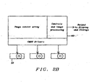
- the ability to drive the actuator with standard CMOS I/O signals allows the electronics of the digital camera module to be integrated into a system-on-chip comprising the image sensor, control circuitry, image processing circuitry and the CMOS I/O drivers, which are coupled to the coils of the stator.
- the gear system of actuator adjusts the moveable optical elements 86 by transferring a stepped movement of the horological step motor to the optical elements through the gear system of the actuator.
- a digital image is captured by the image sensor 87 after the adjustment of the optical elements have been satisfactorily adjusted, and the digital image is outputted from image processing circuitry 88 to a display or storage.
Claims (14)
- Digitalkamera-Modul umfassenda) eine optische Linsen-Anordnung (35, 36), mit einer optischen Achse (30) innerhalb einer kompakten Digitalkamera-Einheit, wobei die optische Linsen-Anordnung mindestens ein bewegliches optisches Element (35, 36) umfasst, wodurch eine Brennweite oder ein Zoomen der optischen Linsen-Anordnung eingestellt wird, um ein Bild auf einem Bildsensor zu projizieren;b) eine Treiber-Einheit, umfassend mindestens einen Stellantrieb (32),
wobei der Stellantrieb weiterhin einen Uhrengangwerk-Schrittmotor nach dem Lavet-Prinzip (52, 53) aufweist, der mit dem beweglichen optischen Element über ein Getriebesystem (55, 56, 60) verbunden ist, das eine integrierte Kupplung (55, 56) aufweist, wodurch die Kupplung das Getriebesystem auskuppelt, wenn mechanische Stoßkräfte auftreten, um Beschädigungen des Getriebesystems durch die Stoßkräfte zu vermeiden;c) eine Steuerungs-Einheit (34), die elektrisch mit dem Stellantrieb verbunden ist,
wobei der Stellantrieb von der Steuerungs-Einheit mittels Verwendung von CMOS-digitalen Ein- /Ausgabe-Signalen angesteuert wird, wodurch die zur Bedienung der digitalen Kamera benötigte Schaltung in ein Ein-Chip-System (SOC: system-on-chip) (40) integriert ist, wobei das Ein-Chip-System umfasst:i) den Bildsensor;ii) einen Steuerungs-Einheiten-Schaltkreis;iii) einen Bildverarbeitungs-Schaltkreis;iv) CMOS-digitale Ein-/Ausgangs-Treiber; undd) wobei der Stellantrieb gesteuert wird, um das bewegliche optische Element einzustellen, um ein fokussiertes Bild auf dem Bildsensor der kompakten Digitalkamera-Einheit zu erzeugen. - Digitalkamera-Modul nach Anspruch 1, wobei der Schrittmotor weiterhin einen Rotor (53) und einen Stator (58) umfasst, wobei der Rotor radial magnetisiert wird und der Stator den Rotor in mindestens einer festen Neutralposition hält, wenn die Phasen des Stators nicht bestromt sind.
- Digitalkamera-Modul nach Anspruch 2, wobei der Stator weiterhin umfasst:a) ein auf eine Grundplatte (54) beschränktes Loch (65), in welchem der Rotor angeordnet ist;b) ein eine Spule (52) tragender Kern; undc) wobei die Spule (52) parallel zur Grundplatte orientiert ist
- Digitalkamera-Modul nach Anspruch 3, wobei die Treiber-Einheit weiterhin eine Ausgangs-Antriebswelle (56) umfasst, wobei die Ausgangs-Antriebswelle mit dem beweglichen optischen Element zur Übertragung von Bewegung zusammenwirkt, wodurch das Drehmoment des Rotors (53) auf die Ausgangs-Antriebswelle über das Getriebesystem (55, 56, 60) übertragen wird.
- Digitalkamera-Modul nach Anspruch 1, wobei das bewegliche optische Element mindestens eine Linse umfasst.
- Digitalkamera-Modul nach Anspruch 1, wobei die Kompakt-Digitalkamera-Einheit, die in einem tragbaren elektronischen Gerät verwendet wird, eines der folgenden Elemente aufweist:a) ein Mobiltelefon;b) eine digitale Einzelbildkamera;c) einen tragbaren digitalen Assistenten; undd) einen Camcorder.
- Digitalkamera-Modul nach Anspruch 1, wobei der Bildsensor einer lichtempfindlichen Vorrichtung entspricht, die mittels einer der folgenden Technologien gefertigt ist;a) einen CCD (Charge Coupled Device) Bildsensor; undb) einen CMOS-Bildsensor.
- Digitalkamera-Modul nach Anspruch 1, wobei die elektrische Steuerungs-Einheit mit dem Bildsensor und den CMOS Ein-/Ausgangs-Schaltkreisen in einer Ein-Chip-System-Konfiguration (40) integriert ist.
- Verfahren zur Bildung bzw. Fertigung eines Kompakt-Digitalkamera-Moduls umfassend:a) Plazieren eines Bildsensors (34) auf einer optischen Achse (30) eines Linsensystems;b) Ausbilden eines beweglichen Abschnitts (35, 36) des Linsensystems, wodurch
mindestens ein bewegliches optisches Element entlang der optischen Achse
bewegbar ist;c) Ausbilden eines elektrischen Uhrengangwerks-Schrittmotors nach dem Lavet-Prinzip in einem Abschnitt eines Stellantriebs (32);d) Ausbilden eines Getriebesystems (55, 56, 60), das mit dem elektrischen Uhrengangswerks-Motor nach dem Lavet-Prinzip verbunden ist (52, 53, 58);e) Einbauen einer Kupplung (55, 56) innerhalb des Getriebesystems, um Getrieberäder während eines mechanischen Stoßes auszukuppeln, um Beschädigung der Getrieberäder zu vermeiden;f) Ausbilden eines Steuerungs-Schaltkreises und eines Bildverarbeitungs-Schaltkreises (40);g) Ansteuern des Stellantriebs (32) mit CMOS-digitalen Ein-/AusgangsSignalen von dem Steuerungs-Schaltkreis (40);h) Einstellen des beweglichen optischen Elements (35, 36) entlang der optischen
Achse (30) mit dem Getriebesystem (55, 56, 66), das von dem elektrischen
Uhrengangwerk-Schrittmotor nach dem Lavet-Prinzip (52, 53, 58) angesteuert
wird; undi) Ausgeben eines digitalen Bildes von der Bildverarbeitungs-Schaltung (40). - Verfahren nach Anspruch 9, wobei das Ausbilden des elektrischen Uhrengangswerks-Schrittmotors nach dem Lavet-Prinzip weiterhin umfasst:a) Ausbilden eines Stators (58);b) Ausbilden eines Rotors (53);c) Magnetisieren eines Rotors in radialer Orientierung; undd) Halten des Rotors durch Magnetisierung in mindestens einer festen Neutralposition, wenn die Phasen des Stators nicht bestromt werden.
- Verfahren nach Anspruch 10, wobei das Ausbilden des Stators weiterhin umfasst:a) Ausbilden eines begrenzenden Lochs (65) in einer Grundplatte (54), in welchem des Rotor (53) angeordnet ist;b) Ausbilden eines eine Spule (52) tragenden Kerns; undc) Positionieren der Spule parallel zur Grundplatte.
- Verfahren nach Anspruch 9, wobei das Ausbilden des Getriebesystems weiterhin umfasst:Ausbilden einer Ausgangs-Antriebswelle (56), welche das von dem elektrischen Schrittmotor erzeugte Drehmoment über das Getriebesystem zu dem beweglichen Abschnitt des Linsensystems überträgt.
- Verfahren nach Anspruch 9, wobei das Ausbilden eines beweglichen Abschnitts des Linsensystems (35, 36) mindestens eine Linse umfasst.
- Verfahren nach Anspruch 9, wobei das Ausbilden des Schaltkreises und des Bildverarbeitungs-Schaltkreises weiterhin eine Integration des Bildsensors mit dem Steuerschaltkreis und dem Bildverarbeitungs-Schaltkreis in einem einzelnen Halbleiter-Chip umfasst und dadurch ein Ein-Chip-System (40) ausgebildet wird.
Priority Applications (4)
| Application Number | Priority Date | Filing Date | Title |
|---|---|---|---|
| DE602006012985T DE602006012985D1 (de) | 2006-09-25 | 2006-09-25 | Kompaktes Kameramodul mit Uhrengangwerkschrittmotor |
| AT06368012T ATE461466T1 (de) | 2006-09-25 | 2006-09-25 | Kompaktes kameramodul mit uhrengangwerkschrittmotor |
| EP06368012A EP1903363B1 (de) | 2006-09-25 | 2006-09-25 | Kompaktes Kameramodul mit Uhrengangwerkschrittmotor |
| US11/527,296 US7657167B2 (en) | 2006-09-25 | 2006-09-26 | Compact camera modules with Lavet stepping-motors as actuators |
Applications Claiming Priority (1)
| Application Number | Priority Date | Filing Date | Title |
|---|---|---|---|
| EP06368012A EP1903363B1 (de) | 2006-09-25 | 2006-09-25 | Kompaktes Kameramodul mit Uhrengangwerkschrittmotor |
Publications (2)
| Publication Number | Publication Date |
|---|---|
| EP1903363A1 EP1903363A1 (de) | 2008-03-26 |
| EP1903363B1 true EP1903363B1 (de) | 2010-03-17 |
Family
ID=37734308
Family Applications (1)
| Application Number | Title | Priority Date | Filing Date |
|---|---|---|---|
| EP06368012A Not-in-force EP1903363B1 (de) | 2006-09-25 | 2006-09-25 | Kompaktes Kameramodul mit Uhrengangwerkschrittmotor |
Country Status (4)
| Country | Link |
|---|---|
| US (1) | US7657167B2 (de) |
| EP (1) | EP1903363B1 (de) |
| AT (1) | ATE461466T1 (de) |
| DE (1) | DE602006012985D1 (de) |
Families Citing this family (6)
| Publication number | Priority date | Publication date | Assignee | Title |
|---|---|---|---|---|
| CN101493646B (zh) * | 2008-01-21 | 2012-05-23 | 鸿富锦精密工业(深圳)有限公司 | 光学镜头检测装置及方法 |
| US8150253B2 (en) | 2009-10-22 | 2012-04-03 | Panasonic Corporation | Imaging apparatus and interchangeable lens |
| EP2341381A1 (de) | 2009-12-15 | 2011-07-06 | Dialog Imaging Systems GmbH | Vorrichtung zur Erkennung des Herunterfallens eines Kameramodules mit Hilfe des Linsenpositionssensors |
| JP6157284B2 (ja) * | 2013-08-30 | 2017-07-05 | オリンパス株式会社 | レンズ駆動装置と、これを適用するレンズ鏡筒及び撮像装置 |
| CN111629124B (zh) * | 2019-02-28 | 2021-10-19 | 宁波舜宇光电信息有限公司 | 光学镜头、摄像模组及相应的组装方法 |
| EP4018269B1 (de) * | 2020-05-28 | 2022-12-07 | Soprod SA | Analoges anzeigemodul für uhren |
Family Cites Families (33)
| Publication number | Priority date | Publication date | Assignee | Title |
|---|---|---|---|---|
| FR823395A (fr) | 1936-09-28 | 1938-01-19 | Hatot | Perfectionnements aux systèmes et appareils de commande électrique à distance, notamment aux moteurs et horloges synchrones |
| US2986683A (en) * | 1956-07-26 | 1961-05-30 | Hatot Leon Ets | Driving balance-wheels more particularly applicable to timing instruments |
| DE1884374U (de) * | 1962-11-07 | 1963-12-12 | Yashica Co Ltd | Drucktastenschalter zur umsteuerung eines gummilinsenantriebs in kinekameras. |
| US3667210A (en) * | 1970-07-06 | 1972-06-06 | Timex Corp | Horological instrument |
| US4294531A (en) * | 1978-04-25 | 1981-10-13 | Polaroid Corporation | Auto-focus movie camera |
| US4504132A (en) * | 1983-02-02 | 1985-03-12 | Eastman Kodak Company | Multifunction electromagnetic actuator and camera control apparatus emloying same |
| CH653521GA3 (de) * | 1983-09-16 | 1986-01-15 | ||
| JPS60158414A (ja) * | 1984-01-27 | 1985-08-19 | Konishiroku Photo Ind Co Ltd | オ−トフオ−カス装置 |
| JPH04261398A (ja) * | 1991-02-12 | 1992-09-17 | Canon Inc | 移動制御装置 |
| US5206983A (en) * | 1991-06-24 | 1993-05-04 | Wisconsin Alumni Research Foundation | Method of manufacturing micromechanical devices |
| CH682872B5 (fr) * | 1992-04-02 | 1994-06-15 | Ebauchesfabrik Eta Ag | Mouvement d'horlogerie comportant des moyens de guidage d'un organe de commande, tel qu'une tige. |
| CH684731B5 (fr) * | 1992-07-20 | 1995-06-15 | Asulab Sa | Moteur piézo-électrique. |
| US5594311A (en) * | 1993-06-15 | 1997-01-14 | Canon Kabushiki Kaisha | Lens controlling apparatus |
| US5685062A (en) * | 1994-07-05 | 1997-11-11 | Ford Motor Company | Self-assembly fabrication method for planar micro-motor |
| US6104878A (en) * | 1995-11-09 | 2000-08-15 | Olympus Optical Co., Ltd. | Failure detection apparatus for storing and displaying the nature of the failure and the time of its occurrence |
| JPH09274127A (ja) | 1996-04-02 | 1997-10-21 | Canon Inc | 光学機器装置 |
| JP3746574B2 (ja) | 1996-08-12 | 2006-02-15 | オリンパス株式会社 | 撮影レンズ装置 |
| FR2753017B1 (fr) * | 1996-08-29 | 1998-10-16 | Imphy Sa | Moteur pas a pas pour horlogerie dont le stator est constitue d'un alliage magnetique doux et alliage magnetique doux |
| US5918078A (en) * | 1996-09-06 | 1999-06-29 | Nikon Corporation | Lens driving device |
| US6614560B1 (en) * | 1997-07-15 | 2003-09-02 | Silverbrook Research Pty Ltd | Integrated camera circuit including image sensor, image processing, and printer drive circuits |
| JP3851027B2 (ja) * | 1999-08-27 | 2006-11-29 | 株式会社リコー | オートフォーカス装置およびカメラ |
| JP3495658B2 (ja) * | 1999-09-13 | 2004-02-09 | ペンタックス株式会社 | レンズ駆動制御装置 |
| US6614998B1 (en) * | 1999-10-18 | 2003-09-02 | Fuji Photo Film Co., Ltd. | Automatic focusing camera and shooting method |
| JP4505050B2 (ja) * | 2001-07-23 | 2010-07-14 | 日本電産コパル株式会社 | ステップモータ |
| US6710950B2 (en) * | 2002-06-05 | 2004-03-23 | Nokia Mobile Phones Limited | Piezoelectric actuator for digital camera optical system |
| JP2004251999A (ja) * | 2003-02-18 | 2004-09-09 | Pentax Corp | カメラのaf駆動機構 |
| JP4050994B2 (ja) * | 2003-03-27 | 2008-02-20 | 日本電産コパル株式会社 | ファンモータ |
| JP2006091265A (ja) | 2004-09-22 | 2006-04-06 | Fuji Photo Film Co Ltd | レンズ駆動装置及び撮像装置並びに光学装置 |
| JP2006091263A (ja) * | 2004-09-22 | 2006-04-06 | Fuji Photo Film Co Ltd | レンズ装置、撮影装置、光学装置、投影装置、撮像装置およびカメラ付き携帯電話 |
| EP1650862B1 (de) * | 2004-10-22 | 2019-08-07 | Dialog Semiconductor GmbH | System-On-Chip für Hochspannungsanwendung |
| TWI329234B (en) * | 2004-12-10 | 2010-08-21 | Hon Hai Prec Ind Co Ltd | Auromatic focusing lens module |
| US7356252B2 (en) * | 2005-11-19 | 2008-04-08 | Foxlink Image Technology Co., Ltd. | Auto-focusing zoom lens mechanism |
| EP1903364A1 (de) * | 2006-09-25 | 2008-03-26 | Dialog Imaging Systems GmbH | Kompaktes Kameramodul mit stationärem Aktuator für Zoom-Module mit beweglichem Blendenverschluss |
-
2006
- 2006-09-25 EP EP06368012A patent/EP1903363B1/de not_active Not-in-force
- 2006-09-25 AT AT06368012T patent/ATE461466T1/de not_active IP Right Cessation
- 2006-09-25 DE DE602006012985T patent/DE602006012985D1/de active Active
- 2006-09-26 US US11/527,296 patent/US7657167B2/en not_active Expired - Fee Related
Also Published As
| Publication number | Publication date |
|---|---|
| EP1903363A1 (de) | 2008-03-26 |
| US7657167B2 (en) | 2010-02-02 |
| DE602006012985D1 (de) | 2010-04-29 |
| US20080075446A1 (en) | 2008-03-27 |
| ATE461466T1 (de) | 2010-04-15 |
Similar Documents
| Publication | Publication Date | Title |
|---|---|---|
| US7670067B2 (en) | Compact camera module with stationary actuator for zoom modules with movable shutter and aperture mechanism | |
| EP1903363B1 (de) | Kompaktes Kameramodul mit Uhrengangwerkschrittmotor | |
| US7292396B2 (en) | Lens device, image pickup device and optical device | |
| US9217841B2 (en) | Compact camera module with zoom and auto-focus actuators sharing the same rotating annular magnet with alternating thick and thin poles | |
| US20060061885A1 (en) | Lens device, imaging device using the same and cell-phone with camera using the same | |
| US20230056609A1 (en) | Folded camera structure with an extended light-folding-element scanning range | |
| US20100220402A1 (en) | Lens barrel and imaging device | |
| KR20120003401A (ko) | 카메라 모듈 | |
| KR20070041341A (ko) | 촬상 장치 | |
| KR100947285B1 (ko) | 자동초점 조절용 경통 구동기구 및 이를 구비한 셔터구동장치 | |
| US7639306B2 (en) | Digital camera module with zoom function and focusing function | |
| WO2010029686A1 (ja) | レンズ鏡筒および撮像装置 | |
| US20080225415A1 (en) | Actuated stepper lens camera module | |
| JP2007104288A (ja) | 撮像装置及び撮像装置の組立方法 | |
| US7582995B2 (en) | Stepping motor, lens device using the same, and imaging device using the same | |
| US7405888B2 (en) | Image taking apparatus | |
| JP2005122026A (ja) | レンズ鏡筒および撮像装置 | |
| KR100795210B1 (ko) | 소형 줌 카메라장치 | |
| JP5047459B2 (ja) | 光量調節装置、撮像光学ユニットおよび撮像装置 | |
| JP2011197163A (ja) | 光学素子駆動装置及び撮像装置 | |
| CN218601649U (zh) | 成像镜头模块、相机模块及电子装置 | |
| JP2012083713A (ja) | レンズ鏡筒 | |
| JP2007086158A (ja) | 撮像装置 | |
| JP2006166653A (ja) | 駆動装置及びレンズ駆動装置 | |
| JP2006094634A (ja) | モータ製造方法、モータ |
Legal Events
| Date | Code | Title | Description |
|---|---|---|---|
| PUAI | Public reference made under article 153(3) epc to a published international application that has entered the european phase |
Free format text: ORIGINAL CODE: 0009012 |
|
| AK | Designated contracting states |
Kind code of ref document: A1 Designated state(s): AT BE BG CH CY CZ DE DK EE ES FI FR GB GR HU IE IS IT LI LT LU LV MC NL PL PT RO SE SI SK TR |
|
| AX | Request for extension of the european patent |
Extension state: AL BA HR MK YU |
|
| 17P | Request for examination filed |
Effective date: 20080926 |
|
| 17Q | First examination report despatched |
Effective date: 20081027 |
|
| AKX | Designation fees paid |
Designated state(s): AT BE BG CH CY CZ DE DK EE ES FI FR GB GR HU IE IS IT LI LT LU LV MC NL PL PT RO SE SI SK TR |
|
| GRAP | Despatch of communication of intention to grant a patent |
Free format text: ORIGINAL CODE: EPIDOSNIGR1 |
|
| GRAS | Grant fee paid |
Free format text: ORIGINAL CODE: EPIDOSNIGR3 |
|
| GRAA | (expected) grant |
Free format text: ORIGINAL CODE: 0009210 |
|
| AK | Designated contracting states |
Kind code of ref document: B1 Designated state(s): AT BE BG CH CY CZ DE DK EE ES FI FR GB GR HU IE IS IT LI LT LU LV MC NL PL PT RO SE SI SK TR |
|
| REG | Reference to a national code |
Ref country code: GB Ref legal event code: FG4D |
|
| REG | Reference to a national code |
Ref country code: CH Ref legal event code: EP |
|
| REG | Reference to a national code |
Ref country code: IE Ref legal event code: FG4D |
|
| REF | Corresponds to: |
Ref document number: 602006012985 Country of ref document: DE Date of ref document: 20100429 Kind code of ref document: P |
|
| REG | Reference to a national code |
Ref country code: NL Ref legal event code: VDEP Effective date: 20100317 |
|
| PG25 | Lapsed in a contracting state [announced via postgrant information from national office to epo] |
Ref country code: LT Free format text: LAPSE BECAUSE OF FAILURE TO SUBMIT A TRANSLATION OF THE DESCRIPTION OR TO PAY THE FEE WITHIN THE PRESCRIBED TIME-LIMIT Effective date: 20100317 |
|
| LTIE | Lt: invalidation of european patent or patent extension |
Effective date: 20100317 |
|
| PG25 | Lapsed in a contracting state [announced via postgrant information from national office to epo] |
Ref country code: SI Free format text: LAPSE BECAUSE OF FAILURE TO SUBMIT A TRANSLATION OF THE DESCRIPTION OR TO PAY THE FEE WITHIN THE PRESCRIBED TIME-LIMIT Effective date: 20100317 Ref country code: AT Free format text: LAPSE BECAUSE OF FAILURE TO SUBMIT A TRANSLATION OF THE DESCRIPTION OR TO PAY THE FEE WITHIN THE PRESCRIBED TIME-LIMIT Effective date: 20100317 Ref country code: FI Free format text: LAPSE BECAUSE OF FAILURE TO SUBMIT A TRANSLATION OF THE DESCRIPTION OR TO PAY THE FEE WITHIN THE PRESCRIBED TIME-LIMIT Effective date: 20100317 Ref country code: LV Free format text: LAPSE BECAUSE OF FAILURE TO SUBMIT A TRANSLATION OF THE DESCRIPTION OR TO PAY THE FEE WITHIN THE PRESCRIBED TIME-LIMIT Effective date: 20100317 Ref country code: PL Free format text: LAPSE BECAUSE OF FAILURE TO SUBMIT A TRANSLATION OF THE DESCRIPTION OR TO PAY THE FEE WITHIN THE PRESCRIBED TIME-LIMIT Effective date: 20100317 |
|
| PG25 | Lapsed in a contracting state [announced via postgrant information from national office to epo] |
Ref country code: EE Free format text: LAPSE BECAUSE OF FAILURE TO SUBMIT A TRANSLATION OF THE DESCRIPTION OR TO PAY THE FEE WITHIN THE PRESCRIBED TIME-LIMIT Effective date: 20100317 Ref country code: SE Free format text: LAPSE BECAUSE OF FAILURE TO SUBMIT A TRANSLATION OF THE DESCRIPTION OR TO PAY THE FEE WITHIN THE PRESCRIBED TIME-LIMIT Effective date: 20100317 Ref country code: RO Free format text: LAPSE BECAUSE OF FAILURE TO SUBMIT A TRANSLATION OF THE DESCRIPTION OR TO PAY THE FEE WITHIN THE PRESCRIBED TIME-LIMIT Effective date: 20100317 Ref country code: NL Free format text: LAPSE BECAUSE OF FAILURE TO SUBMIT A TRANSLATION OF THE DESCRIPTION OR TO PAY THE FEE WITHIN THE PRESCRIBED TIME-LIMIT Effective date: 20100317 Ref country code: BE Free format text: LAPSE BECAUSE OF FAILURE TO SUBMIT A TRANSLATION OF THE DESCRIPTION OR TO PAY THE FEE WITHIN THE PRESCRIBED TIME-LIMIT Effective date: 20100317 Ref country code: GR Free format text: LAPSE BECAUSE OF FAILURE TO SUBMIT A TRANSLATION OF THE DESCRIPTION OR TO PAY THE FEE WITHIN THE PRESCRIBED TIME-LIMIT Effective date: 20100618 Ref country code: ES Free format text: LAPSE BECAUSE OF FAILURE TO SUBMIT A TRANSLATION OF THE DESCRIPTION OR TO PAY THE FEE WITHIN THE PRESCRIBED TIME-LIMIT Effective date: 20100628 Ref country code: CY Free format text: LAPSE BECAUSE OF FAILURE TO SUBMIT A TRANSLATION OF THE DESCRIPTION OR TO PAY THE FEE WITHIN THE PRESCRIBED TIME-LIMIT Effective date: 20100317 |
|
| PG25 | Lapsed in a contracting state [announced via postgrant information from national office to epo] |
Ref country code: SK Free format text: LAPSE BECAUSE OF FAILURE TO SUBMIT A TRANSLATION OF THE DESCRIPTION OR TO PAY THE FEE WITHIN THE PRESCRIBED TIME-LIMIT Effective date: 20100317 Ref country code: IS Free format text: LAPSE BECAUSE OF FAILURE TO SUBMIT A TRANSLATION OF THE DESCRIPTION OR TO PAY THE FEE WITHIN THE PRESCRIBED TIME-LIMIT Effective date: 20100717 Ref country code: CZ Free format text: LAPSE BECAUSE OF FAILURE TO SUBMIT A TRANSLATION OF THE DESCRIPTION OR TO PAY THE FEE WITHIN THE PRESCRIBED TIME-LIMIT Effective date: 20100317 Ref country code: BG Free format text: LAPSE BECAUSE OF FAILURE TO SUBMIT A TRANSLATION OF THE DESCRIPTION OR TO PAY THE FEE WITHIN THE PRESCRIBED TIME-LIMIT Effective date: 20100617 |
|
| PLBE | No opposition filed within time limit |
Free format text: ORIGINAL CODE: 0009261 |
|
| STAA | Information on the status of an ep patent application or granted ep patent |
Free format text: STATUS: NO OPPOSITION FILED WITHIN TIME LIMIT |
|
| PG25 | Lapsed in a contracting state [announced via postgrant information from national office to epo] |
Ref country code: PT Free format text: LAPSE BECAUSE OF FAILURE TO SUBMIT A TRANSLATION OF THE DESCRIPTION OR TO PAY THE FEE WITHIN THE PRESCRIBED TIME-LIMIT Effective date: 20100719 Ref country code: DK Free format text: LAPSE BECAUSE OF FAILURE TO SUBMIT A TRANSLATION OF THE DESCRIPTION OR TO PAY THE FEE WITHIN THE PRESCRIBED TIME-LIMIT Effective date: 20100317 |
|
| 26N | No opposition filed |
Effective date: 20101220 |
|
| PG25 | Lapsed in a contracting state [announced via postgrant information from national office to epo] |
Ref country code: IT Free format text: LAPSE BECAUSE OF FAILURE TO SUBMIT A TRANSLATION OF THE DESCRIPTION OR TO PAY THE FEE WITHIN THE PRESCRIBED TIME-LIMIT Effective date: 20100317 |
|
| PG25 | Lapsed in a contracting state [announced via postgrant information from national office to epo] |
Ref country code: MC Free format text: LAPSE BECAUSE OF NON-PAYMENT OF DUE FEES Effective date: 20100930 |
|
| REG | Reference to a national code |
Ref country code: CH Ref legal event code: PL |
|
| GBPC | Gb: european patent ceased through non-payment of renewal fee |
Effective date: 20100925 |
|
| REG | Reference to a national code |
Ref country code: FR Ref legal event code: ST Effective date: 20110531 |
|
| REG | Reference to a national code |
Ref country code: DE Ref legal event code: R119 Ref document number: 602006012985 Country of ref document: DE Effective date: 20110401 |
|
| PG25 | Lapsed in a contracting state [announced via postgrant information from national office to epo] |
Ref country code: CH Free format text: LAPSE BECAUSE OF NON-PAYMENT OF DUE FEES Effective date: 20100930 Ref country code: IE Free format text: LAPSE BECAUSE OF NON-PAYMENT OF DUE FEES Effective date: 20100925 Ref country code: FR Free format text: LAPSE BECAUSE OF NON-PAYMENT OF DUE FEES Effective date: 20100930 Ref country code: DE Free format text: LAPSE BECAUSE OF NON-PAYMENT OF DUE FEES Effective date: 20110401 Ref country code: LI Free format text: LAPSE BECAUSE OF NON-PAYMENT OF DUE FEES Effective date: 20100930 |
|
| PG25 | Lapsed in a contracting state [announced via postgrant information from national office to epo] |
Ref country code: GB Free format text: LAPSE BECAUSE OF NON-PAYMENT OF DUE FEES Effective date: 20100925 |
|
| PG25 | Lapsed in a contracting state [announced via postgrant information from national office to epo] |
Ref country code: HU Free format text: LAPSE BECAUSE OF FAILURE TO SUBMIT A TRANSLATION OF THE DESCRIPTION OR TO PAY THE FEE WITHIN THE PRESCRIBED TIME-LIMIT Effective date: 20100918 Ref country code: LU Free format text: LAPSE BECAUSE OF NON-PAYMENT OF DUE FEES Effective date: 20100925 |
|
| PG25 | Lapsed in a contracting state [announced via postgrant information from national office to epo] |
Ref country code: TR Free format text: LAPSE BECAUSE OF FAILURE TO SUBMIT A TRANSLATION OF THE DESCRIPTION OR TO PAY THE FEE WITHIN THE PRESCRIBED TIME-LIMIT Effective date: 20100317 |