EP1902787A2 - Appareil d'application de produit fluide, en particulier d'adhésif thermofusible - Google Patents
Appareil d'application de produit fluide, en particulier d'adhésif thermofusible Download PDFInfo
- Publication number
- EP1902787A2 EP1902787A2 EP07117015A EP07117015A EP1902787A2 EP 1902787 A2 EP1902787 A2 EP 1902787A2 EP 07117015 A EP07117015 A EP 07117015A EP 07117015 A EP07117015 A EP 07117015A EP 1902787 A2 EP1902787 A2 EP 1902787A2
- Authority
- EP
- European Patent Office
- Prior art keywords
- plunger
- fluid
- outlet passages
- main body
- distributor passage
- Prior art date
- Legal status (The legal status is an assumption and is not a legal conclusion. Google has not performed a legal analysis and makes no representation as to the accuracy of the status listed.)
- Granted
Links
Images


Classifications
-
- B—PERFORMING OPERATIONS; TRANSPORTING
- B05—SPRAYING OR ATOMISING IN GENERAL; APPLYING FLUENT MATERIALS TO SURFACES, IN GENERAL
- B05C—APPARATUS FOR APPLYING FLUENT MATERIALS TO SURFACES, IN GENERAL
- B05C5/00—Apparatus in which liquid or other fluent material is projected, poured or allowed to flow on to the surface of the work
- B05C5/02—Apparatus in which liquid or other fluent material is projected, poured or allowed to flow on to the surface of the work the liquid or other fluent material being discharged through an outlet orifice by pressure, e.g. from an outlet device in contact or almost in contact, with the work
- B05C5/0254—Coating heads with slot-shaped outlet
- B05C5/0258—Coating heads with slot-shaped outlet flow controlled, e.g. by a valve
-
- B—PERFORMING OPERATIONS; TRANSPORTING
- B05—SPRAYING OR ATOMISING IN GENERAL; APPLYING FLUENT MATERIALS TO SURFACES, IN GENERAL
- B05C—APPARATUS FOR APPLYING FLUENT MATERIALS TO SURFACES, IN GENERAL
- B05C5/00—Apparatus in which liquid or other fluent material is projected, poured or allowed to flow on to the surface of the work
- B05C5/02—Apparatus in which liquid or other fluent material is projected, poured or allowed to flow on to the surface of the work the liquid or other fluent material being discharged through an outlet orifice by pressure, e.g. from an outlet device in contact or almost in contact, with the work
- B05C5/0254—Coating heads with slot-shaped outlet
- B05C5/0266—Coating heads with slot-shaped outlet adjustable in length, e.g. for coating webs of different width
-
- B—PERFORMING OPERATIONS; TRANSPORTING
- B05—SPRAYING OR ATOMISING IN GENERAL; APPLYING FLUENT MATERIALS TO SURFACES, IN GENERAL
- B05C—APPARATUS FOR APPLYING FLUENT MATERIALS TO SURFACES, IN GENERAL
- B05C5/00—Apparatus in which liquid or other fluent material is projected, poured or allowed to flow on to the surface of the work
- B05C5/02—Apparatus in which liquid or other fluent material is projected, poured or allowed to flow on to the surface of the work the liquid or other fluent material being discharged through an outlet orifice by pressure, e.g. from an outlet device in contact or almost in contact, with the work
- B05C5/027—Coating heads with several outlets, e.g. aligned transversally to the moving direction of a web to be coated
- B05C5/0275—Coating heads with several outlets, e.g. aligned transversally to the moving direction of a web to be coated flow controlled, e.g. by a valve
- B05C5/0279—Coating heads with several outlets, e.g. aligned transversally to the moving direction of a web to be coated flow controlled, e.g. by a valve independently, e.g. individually, flow controlled
Definitions
- the invention concerns an apparatus for applying fluids such as adhesive, in particular hot melt adhesive, to a substrate which is movable relative to the apparatus, comprising a main body and an application valve for selectively interrupting or enabling the flow of fluid, wherein the main body can be connected to a fluid source and has a slot-shaped nozzle opening communicating with a distributor passage and a plunger which is arranged movably in the distributor passage and by means of which the length of the distributor passage, which can be acted upon with fluid, is variable.
- fluids such as adhesive, in particular hot melt adhesive
- Apparatuses of that kind are frequently also referred to as an applicator head and are used for example when substrates in film or layer form such as labels are to be coated over the surface thereof with liquid adhesive, for example hot melt adhesive.
- the adhesive which is capable of flow is usually kept in readiness in a fluid source such as a melting device. That fluid source is in communication with a main body of the apparatus by way of a hose connection.
- Adhesive which is capable of flow is conveyed into the apparatus through suitable bores by means of a conveyor means and further conveyed through a distributor passage and in that situation passes a valve body of an application valve.
- the distributor passage communicates with a slot-shaped nozzle opening from which the adhesive is delivered and applied to a substrate.
- the nozzle opening is usually in the form of an elongate slot.
- the length of the operative portion of the slot can be adjusted by a plunger arranged movably in the distributor passage. In a first end position, the plunger is positioned minimally within the distributor passage and the screwthreaded spindle moving the plunger protrudes over the nozzle arrangement almost with its entire length. In a second end position, i.e. in a position in which the length of the operative portion of the slot is minimal, the plunger is maximally inserted into the distributor passage.
- Such an apparatus is known for example from DE 299 08 150 .
- the nozzle opening When coating labels which are applied for example to bottles the nozzle opening is usually disposed in a vertical orientation, that is to say the slot-shaped outlet opening extends substantially vertically.
- the force of gravity produces an unwanted flow component of the fluid downwardly in the longitudinal direction of the slot-shaped outlet opening.
- dripping manifests itself as a detrimental effect by virtue of excess adhesive running down the nozzle opening and uncontrolledly hardening with the passage of time. Consequently, prior to each fresh start-up of the apparatus, the adhesive which has run down has to be laboriously removed in order to guarantee a uniform application pattern in the upcoming use.
- the application pattern has a plurality of spaced strips usually entail employing application apparatuses having a nozzle arrangement, which use nozzle plates having a plurality of spaced apertures so that spaced slot-shaped outlet openings are afforded within the nozzle arrangement, through which the adhesive is delivered in strip form and thus applied to the substrate.
- the procedure involved is such that the nozzle plate is removed and a fresh nozzle plate involving a different geometry is fitted into the nozzle arrangement. That procedure is relatively laborious and tedious. The same applies in the situation where the application width has to be altered.
- the object of the present invention is to provide and improve an apparatus of the kind set forth in the opening part of this specification, in which influences of the force of gravity on the flow within the slot-shaped nozzle opening are reduced. Furthermore, in accordance with another aspect, the object of the invention is to provide an apparatus which, particularly when the outlet opening is arranged vertically, avoids detrimental influence on the application pattern, in particular minimising adhesive running down while the apparatus is in a stopped condition. In accordance with a further partial aspect, the object of the invention is to provide an apparatus in which the form of the outlet opening and in particular the width of the application pattern can be altered as easily as possible.
- the screwthreaded spindle has to be at least as long as the part of the plunger that protrudes over the distributor passage, when the plunger is positioned in the first end position. Since the screwthreaded spindle has to be supported and needs an engagement portion for turning the spindle placed on its end facing away from the distributor passage, further space is needed for the drive device.
- the drive device not only requires space in prolongation of the longitudinal axis of the distributor passage, but also radially hereto, in particular for the supporting device for supporting the screwthreaded spindle. The fact that a relatively large space is needed for the drive device of the plunger can be negative.
- the extension of the drive device in the longitudinal axis of the distributor passage can be disadvantageous since the drive device can collide with neighbouring machines as labelling machines or with walls. Therefore the object of a further partial aspect of the invention is to make the apparatus more compact in construction without however detrimentally affecting the displaceability of the plunger.
- the object is attained by the invention in that the nozzle opening communicates with the distributor passage by means of a plurality of mutually spaced outlet passages.
- the plurality of mutually spaced outlet passages, together with the movable plunger, means that the application pattern and in particular the width of application can be altered in a simple fashion.
- the segmentation of the slot between the nozzle opening and the distributor passage by means of the outlet passages means that flow components in the direction of the longitudinal direction of the slot-shaped outlet passage are substantially prevented or reduced. That leads to a uniform application effect.
- the flow of fluid through the outlet passages can be selectively enabled or interrupted by means of the plunger.
- the position of the plunger makes it possible to select which of the outlet passages have adhesive flowing therethrough.
- the fact that the plunger has a plunger portion which forms a narrow annular gap between its outer peripheral surface and the inner surface of the distributor passage means that the portion of the distributor passage, which is occupied by the plunger, is sealed off so that no fluid can penetrate into that portion. Consequently, outlet passages which are disposed in the portion of the distributor passage, which is sealed off by the plunger, can no longer have fluid flowing therethrough, whereby no fluid also issues from the nozzle opening in that portion.
- the width of the application surface is variable stepwise by the number of outlet passages through which fluid flows.
- the number of the outlet passages through which fluid flows is determined by the position of the plunger in the distributor passage.
- the above-described sealing action of the end of the plunger, which is in contact with the fluid means that the outlet passages can be characterised in the following fashion: in dependence on the position of the plunger in the distributor passage the outlet passages - as considered in the direction of flow of the fluid - are disposed either upstream of or downstream of the end of the plunger, which is in contact with the fluid.
- Outlet passages which are upstream of the end of the plunger have fluid flowing therethrough while outlet passages which are disposed downstream of the end of the plunger are cut off from the feed of fluid.
- the position of the plunger in the distributor passage also determines the width of the application surface.
- the distributor passage, the outlet passages and the nozzle opening are provided in a nozzle arrangement which is separable from the main body. That is advantageous from the point of view of production engineering as it makes it possible for structural features which are required for producing the desired adhesive application pattern to be implemented in a simple manner. Examples of such structural features could be projections for flow breakaway edges or openings for a locally increased provision of adhesive, as are described in DE 20 308 257 . Furthermore it is possible to use different materials for the nozzle arrangement from the main body, which are better suited to implementing the above-mentioned structural features.
- a preferred embodiment of the invention provides that the nozzle arrangement comprises a first block portion and a second block portion which are releasably connectable to each other and to the main body. Subdividing the nozzle arrangement into two block portions provides that accessibility both to the distributor passage and also the outlet passages is markedly enhanced so that they can be cleaned and cleared of hardened adhesive residues in a simple fashion.
- outlet passages are formed by depressions on the corresponding surface of only one of the block portions.
- the advantage in terms of production engineering is that only one block portion has to be worked or machined so that manufacturing time and cost can be reduced.
- a further advantage is that only one block portion has to be exchanged if the use involved makes it necessary to employ outlet passages of different geometrical properties.
- the outlet passages are of a cross-section which enlarges towards the nozzle opening.
- the enlargement in cross-section has the advantage that, with corresponding dimensioning, the fluid delivered by the nozzle opening forms a closed application surface, but nonetheless at the side adjoining the distributor passage, the intermediate space between the passage entrances is large enough to have a sufficiently large sealing area so that the outlet passages can be securely closed off by the plunger.
- the plunger does not have to be so accurately positioned in order to prevent an outlet passage being only partially closed by the plunger.
- the invention is further distinguished in that the outlet passages are of a substantially rectangular cross-section. That is more desirable for reasons related to production engineering, in comparison with round cross-sections, as rectangular cross-sections can be more easily milled into the corresponding surface of the block portion of the nozzle arrangement.
- the spacing between the outlet passages is so selected that the fluid delivered by the nozzle opening forms a closed application surface which is desired in relation to some situations of use.
- An essential aspect in that respect is that, when applying adhesive, in particular hot melt adhesive, a particularly uniform thickness of the layer applied is achieved. The uniformity of that thickness of the layer has a particular effect on the quality of the adhesive join. Particularly when glueing labels to transparent containers such as for example bottles, surface portions with an increased or reduced application of adhesive are detrimentally conspicuous.
- the spacing between the outlet passages is so selected that the fluid delivered by the nozzle opening forms an application surface which comprises a plurality of mutually spaced strips.
- the adhesive it is sufficient for the adhesive to be applied to the contact surface, in a plurality of mutually spaced strips. In that fashion it is possible to achieve a saving in adhesive, without having to accept a serious limitation in the quality of the adhesive join.
- a development of the invention provides that a rotatably supported screwthreaded spindle is in engagement with a screwthreaded body which is rigidly connected to the plunger. That arrangement makes it possible for the position of the plunger in the distributor passage to be precisely adjusted without the plunger being tilted in that case, whereby its sealing action could be lost. Besides the possibility of adjusting the plunger position, the screwthreaded spindle also provides that the adjusted position of the plunger is maintained even under the pressure which is built up due to the flow of fluid in the distributor passage. Alternatively linear adjustment of the position of the plunger can also be embodied by a chain drive, whereby the structural space required can be markedly reduced. A configuration of that kind is described in detail in EP 1 501 640 .
- a development of the invention provides that the screwthreaded spindle is coupled by way of a worm transmission to a rotary knob for manual adjustment of the position of the plunger in the distributor passage.
- the use of a rotary knob for actuating the screwthreaded spindle makes manual adjustment of the position of the plunger easier and more convenient.
- it may be advantageous to alter the directional configuration of the rotary axis for example if the apparatus is not readily accessible from a side.
- Such a change in the directional configuration of the rotary axis can be implemented by means of a worm transmission of suitable design.
- the use of a transmission optionally makes it possible to achieve a step-up transmission ratio, whereby on the one hand the position of the plunger can be still more accurately set while on the other hand the application of force required for that purpose is markedly reduced.
- a preferred embodiment of the invention is distinguished in that a latching engagement element is arranged between the screwthreaded spindle and the transmission and co-operates with the rotary knob, the transmission and the screwthreaded spindle in such a way that the plunger is displaceable discontinuously by the spacing of two outlet passages relative to each other in the distributor passage.
- the latching engagement element comprises a spring pressure-loaded ball which, after a rotary movement of 360o, noticeably latchingly engages into a recess. A rotary movement of the latching engagement element through 360o provides that the plunger is displaced precisely by the spacing of two outlet passages.
- Discontinuous displaceability of the plunger in that way by the spacing between two outlet passages relative to each other is therefore helpful in ensuring that an outlet passage either has no fluid at all flowing therethrough or has fluid flowing completely therethrough.
- the screwthreaded spindle, the latching engagement element and the plunger are so matched to each other that the end of the plunger, which is in contact with the fluid, is respectively positioned directly at the boundary surface - which is the upper boundary surface as considered in the direction of flow of the fluid - of the respective last outlet passage through which fluid is flowing.
- the rotary knob and the worm transmission can also be omitted and the screwthreaded spindle can be rotated directly by actuation of the latching engagement element.
- the plunger is movable with a drive device in the distributor passage and the length of the distributor passage, which can be acted upon with fluid, is variable, wherein advantageously the plunger can be fixed in various positions by means of a fixing device.
- the fixing device performs the fixing function for the plunger.
- the drive device can be separated from the plunger without the plunger being capable of displacement.
- the fixing device is in the form of a clamping device.
- the clamping device makes it possible for the movement of the plunger along the longitudinal axis of the distributor passage to be selectively enabled or prevented, while involving a relatively low level of structural complication and expenditure and in a reliable fashion.
- the clamping device has a housing and a clamping element which is movable therein by means of a clamping screw and which embraces the plunger. That provides a clamping device which is of a compact and simple structure and which is inexpensive to produce.
- the invention is advantageously distinguished in that the clamping device is releasably connectable to the nozzle arrangement and/or the main body.
- the nozzle arrangement which is used as standard and/or the main body only have to be modified in such a way that the clamping device can be secured thereto. Such a modification can involve the provision of screwthreads for screws, which would signify only minor intervention operations. Special manufacturing designs for the main body and/or nozzle arrangements are not necessary for that purpose.
- the clamping device can be quickly fitted and in the event of failure rapidly replaced.
- the nozzle arrangement does not have to be separated from the main body for that purpose.
- the drive device includes a holding device, a screwthreaded spindle mounted therein, a screwthreaded body, a guide rod and/or a latching engagement element.
- a drive device of such a design configuration manages without involving complicated, expensive parts which are susceptible to trouble.
- the individual components are mass-produced items which are quickly available and inexpensive.
- the drive device according to the invention can be easily rapidly fitted and dismantled again. There is no need for special tools or especially trained operating personnel.
- the individual parts of the drive device form an interconnected unit and are connectable as a whole releasably to the main body and/or the nozzle arrangement and the plunger. That design configuration for the drive device further facilitates assembly and dismantling.
- the drive device can be completely assembled before it is mounted to the main body and/or to the nozzle arrangement. The same also applies to the situation where the drive unit is to be removed. That is advantageous insofar as the down times of the application apparatus can be kept short, which in turn involves economic advantages.
- the drive device can be fixed with only one fixing element, in particular a screw to the main body and/or to the nozzle arrangement. That means that the drive device can be even more quickly mounted to the main body and/or to the nozzle arrangement and released again. The amount of time required for that purpose is further reduced.
- the latching engagement element co-operates with the screwthreaded spindle in such a way that the plunger is displaceable discontinuously in each case by the spacing of two adjacent mutually spaced outlet passages.
- the latching engagement element assists the operator who rotates the screwthreaded spindle in displacing the plunger into the correct position in the distributor passage in order to prevent an outlet passage being only partially closed by the plunger, which would have a detrimental effect on the pattern with which the adhesive is applied to the substrate.
- the plunger has markings, the spacing of which corresponds to the spacing of two adjacent outlet passages.
- the markings serve as a check both that the plunger is in the correct position in the distributor passage and also that the latching engagement element and the screwthreaded spindle co-operate correctly.
- the markings provide assistance in being able to better determine the position of the plunger in the distributor passage.
- the markings can be consecutively numbered, thereby providing information about the number of outlet passages which are acted upon with fluid and accordingly the width of the adhesive application pattern on the substrate.
- an apparatus for applying fluids such as adhesive, in particular hot melt adhesive, to a substrate which is movable relative to the apparatus, comprising a main body and an application valve for selectively interrupting or enabling the flow of fluid, wherein the main body can be connected to a fluid source and has a slot-shaped nozzle opening communicating with a distributor passage and a plunger which is arranged movably in the distributor passage and by means of which the length of the distributor passage, which can be acted upon with fluid, is variable, in which preferably the plunger can be fixed in various positions by means of a fixing device.
- the fixing device performs the fixing function for the plunger.
- the apparatus is distinguished by preamble of claim 23 wherein advantageously the individual parts of the drive device form an interconnected unit and are connectable as a whole releasably to the main body and/or the nozzle arrangement and the plunger. That design configuration for the drive device further facilitates assembly and dismantling.
- the drive device can be completely assembled before it is mounted to the main body and/or to the nozzle arrangement. The same also applies to the situation where the drive unit is to be removed. That is advantageous insofar as the down times of the application apparatus can be kept short, which in turn involves economic advantages.
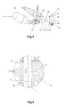
- the apparatus 10 shown in Figure 1 serves for applying fluids such as adhesive, in particular hot melt adhesive, to a substrate which is movable relative to the apparatus 10 in the direction of the indicated arrow 72.
- the apparatus includes an electropneumatically actuable application valve 22 connected to a main body 12.
- a nozzle arrangement 70 is releasably secured at one side of the main body 12 by means of screw connections 44 and centered with pins 48 ( Figure 2).
- the nozzle arrangement includes two block portions 50 and 52.
- the apparatus 10 can be connected by way of a hose 20 to a fluid source (not shown).
- the apparatus 10 is supplied with electrical power by way of a connecting element 36.
- the apparatus 10 can be fixed in position by means of fixing elements 38.
- the electrically actuable application valve 22 has an electrical connection 82 and a compressed air connection 80, by means of which it is possible to connect a compressed air source (not shown). That affords a possible way of selectively interrupting or enabling the flow of fluid through the main body 12 and providing for an intermittent application of adhesive.
- the nozzle arrangement 70 has a substantially slot-shaped nozzle opening 54 through which the fluid is delivered and applied to the substrate.
- the nozzle arrangement includes a cylindrical distributor passage 14 (see Figures 3 and 4) in which a plunger 16 is movably arranged.
- the plunger 16 is displaceable in the distributor passage 14 by means of the adjusting device 58.
- the plunger 16 has a plunger head 34 which seals off the distributor passage 14.
- the plunger head 34 can extend over the entire length of the plunger 16.
- the adjusting device 58 includes a holding device 42 which is releasably secured on a surface 56 of the main body 12.
- a mounting plate 68 is also connected to the holding device 42.
- a screwthreaded spindle 32 is rotatably supported by means of a plain bearing (not shown) in the mounting plate 68 and in the surface 56 of the main body 12.
- the screwthreaded spindle 32 is rotatable by means of a rotary knob 24.
- the rotary knob 24 is connected to the screwthreaded spindle 32 by way of a worm transmission 26 so that the axis of the rotary movement can be altered. That arrangement affords the possibility of orienting the rotary knob 24 in such a way that it is more readily accessible. That is advantageous in particular when there is not much structural space available for the apparatus 10.
- the holding device 42 is further equipped with a scale, by means of which it is possible to ascertain the exact position of the plunger 16 in the distributor passage 14.
- Figure 3 shows the flow of fluid from the fluid source (not shown) into the distributor passage 14.
- a conveyor means such as for example a pump provides that the fluid is conveyed through the hose 20 connected to a hose connection 74 in which a filter is arranged into a bore 64 in the main body 12.
- the bore 64 communicates with a bore portion 62 which is sealed off in a manner not shown here above and below the mouth opening of the bore 64 by means of O-rings which are integrated into a cylindrical hollow body of the application valve 22.
- the fluid passes into a passage (not shown) which is oriented in alignment with the bore 65, in the hollow body of the application valve 22, in which a valve needle 84 is disposed. The passage enlarges further downstream.
- valve needle 84 is also enlarged and forms a valve body which is of such a dimension that the flow of fluid is interrupted by the valve body bearing against complementary surfaces of the enlargement of the passage.
- the dripping effect described hereinbefore can be reduced.
- the bore 65 communicates with a bore 66 disposed in the block portion 50.
- the bore 66 communicates with the distributor passage 14 which is delimited and sealed off laterally by the block portions 50 and 52 and at its first end face by the sealing plate 46 and a sealing element 76 which is optionally screwed therein, and at its second end face by the plunger 16.
- FIG 4 shows in greater detail a portion of the distributor passage 14 illustrated in Figure 2.
- the plunger 16 has an end 34 which is in contact with the fluid and which forms a narrow annular gap between its outer peripheral surface and the inner surface of the distributor passage 14 so that the portion of the distributor passage 14, which is occupied by the plunger 16, is sealed off and no fluid can penetrate into that portion.
- the block portion 50 further has outlet passages 18 which communicate with the portion, which is acted upon with fluid, of the distributor passage 14 and the nozzle opening 54.
- the fluid conveyed into the distributor passage 14 flows on through the opened outlet passages 18a and 18b to the nozzle opening 54, through which the fluid is delivered and applied to the substrate.
- the outlet passages identified by reference 18c in Figure 4 are closed by the plunger and do not have fluid flowing therethrough.
- outlet passages through which fluid flows and outlet passages which are closed can be selected and the width of the resulting application surface can be varied, by the position of the plunger. It is advantageous from the fluidics point of view that the outlet passages are either completely opened or entirely closed. A partially opened outlet passage would give rise to irregularities in the feed of fluid so that a uniform application would not be achieved.
- the plunger 16 is so positioned that a substantially displacement-free and edge-free transition is formed in the distributor passage 14, between the plunger end 34 and the last outlet passage 18b through which fluid flows. As shown in Figure 4, that is achieved when the plunger end 34 is positioned in flush relationship with an upper boundary surface 78 of the respective last outlet passage 18 through which fluid flows.
- the corresponding positioning of the plunger 16 is achieved by the provision of a latching engagement element 28 ( Figure 2) between the worm transmission 26 and the screwthreaded spindle 32, the latching engagement element 28 providing that the plunger 16 is displaced discontinuously by the spacing of two adjacent outlet passages 18.
- Figure 5 shows a partial side view section of the apparatus 10 according to the invention.
- the Figure shows how the plunger 16 co-operates with the distributor passage 14, the sealing plate 46 together with an optional sealing element 76 and the outlet passages 18.
- the rotary movement of the rotary knob 24 is transmitted to the screwthreaded spindle 42 by way of the worm transmission 26 and the rotary movement is converted into a longitudinal movement by means of the screwthreaded body 30 and transmitted to the plunger 16 rigidly connected to the screwthreaded body 30.
- the fixing elements 38 are mounted to the main body 12.
- the lateral parts of the application valve 22, in particular the lateral connection 82 for the supply of compressed air, can be seen in the background.
- Figure 6 shows a plan view of the apparatus 10 according to the invention. Shown therein are the two block portions 50 and 52 which are joined to the main body 12 and form the nozzle opening 54. The position of the screwthreaded spindle 32 and the plunger 16 relative to each other as well as the position of the rotary knob 24 can also be clearly seen. Furthermore Figure 6 shows the fixing element 38, the two connections 80 and 82 for the supply of compressed air for the application valve 22 as well as the cable connection 36 for supplying the apparatus with electrical power.
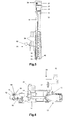
- FIGs 7a and 7b show a further configuration of the present invention in which a drive device 86 is designed to be removable.
- the drive device 86 has a holding device 42, a mounting plate 68 screwed thereto, a screwthreaded spindle 98, a screwthreaded body 100, a guide rod 102 and/or a latching engagement element 104.
- the holding device 42 of the drive device 86 is connected to the main body 12 by way of a connecting element 106 (see Figure 8) on the surface 56.
- the holding device 42 can also be connected to the nozzle arrangement 70 and/or the main body 12.
- the mounting plate 68 is in the form of a separate component releasably connected to the holding device 42 but it can also be in the form of an integral component part of the holding device 42.
- the screwthreaded spindle 98 is rotatably supported by means of plain or rolling bearings (not shown) between the mounting plate 68 and the surface 56.
- the screwthreaded spindle 98 is connected to the screwthreaded body 100 which is mounted displaceably on the guide rod 102 and can be moved along the longitudinal axis of the guide rod 102 between the mounting plate 68 and the surface 56 of the main body 12 by rotation of the screwthreaded spindle 98.
- the screwthreaded body 100 is releasably connected to the plunger 16.
- the screwthreaded body 100 has an opening 114 into which it is possible to fit a portion 112 of the plunger 16, which is of a reduced diameter.
- the movements of the screwthreaded body 100 in the direction of the longitudinal axis of the distributor passage 14 are transmitted from the screwthreaded body 100 to the plunger 16 by positively locking engagement in the regions within which the diameter of the plunger 16 enlarges again at the two ends of the portion 112.
- the screwthreaded spindle 98 is actuated by rotation of the latching engagement element 104.
- the screwthreaded spindle 98 can be actuated by a suitable tool, for example a spanner, which is fitted on to an engagement portion 108 of the screwthreaded spindle 98. That option presents itself in the situation where the latching engagement element is not accessible or is only accessible with difficulty.
- a suitable tool for example a spanner
- the worm transmission 26 and the rotary knob 24 can be fitted on to the engagement portion 108 in order in that way to afford better accessibility and, with a suitable step-up transmission ratio, easier rotatability of the screwthreaded spindle 98.
- the plunger 16 When the plunger 16 is in the desired position, that is to say the desired length of the distributor passage 14 which can be acted upon with fluid is reached, the plunger 16 is fixed in position by means of a clamping device 110. That ensures that the plunger 16 does not move even when fluid such as hot melt adhesive is conveyed under high pressure through the distributor passage 28.
- the individual parts of the drive device 86 form an interconnected unit which can be releasably connected as a whole to the main body 12 and/or the nozzle arrangement 70 and the plunger 16.
- the drive device 86 can be fixed with only one connecting element 106 and a screw 107 to the main body 12 and/or to the nozzle arrangement 70.
- the connecting element 106 is in the form of a substantially cuboidal body.
- the aim of that connecting element 106 is to place the connection between the drive device 86 and the main body 12 in such a way that it is easily accessible. In that respect it is advantageous for the connection not to be placed directly on the surface 56 but spaced somewhat therefrom so that the head of the screw 107 is not beside the clamping device 110. In that way the screw 107 can be more easily reached and tightened either by hand or with a spanner.
- the pitch of the screwthread of the screwthreaded spindle 98 is so selected that a rotary movement of the screwthreaded spindle 98 through 360o causes an axial displacement of the screwthreaded body 100 and thus also the plunger 16 through precisely the spacing between two adjacent outlet passages.
- the plunger 16 includes markings 122, for example in the form of grooves, the spacing of which precisely corresponds to the spacing of two adjacent outlet passages.
- the markings 122 are so arranged that they are aligned with the top side of the clamping device 110 when the plunger 16 has been displaced by the correct distance.
- this affords a guarantee that the plunger 16 is in the correct position and for example the outlet passage 18b adjacent to the end face of the plunger head 34 is not partially closed. The consequence of that would be that an irregular adhesive application pattern would be produced at the edge region, which is undesirable.
- Figures 7a and 7b show the apparatus 10 according to the invention in such a way that the plunger 16 is in its second end position.
- the drive device 86 is fitted in Figure 7a whereas it is removed in Figure 7b.
- the region of the nozzle opening 54 is almost freely accessible, when the drive device 86 is removed.
- FIG. 8 shows the clamping device 110 in greater detail.
- the clamping device 110 has a housing 90 which is releasably connected to the nozzle arrangement 70 and/or the main body 12.
- the housing 90 has a U-shaped opening 116 which embraces the plunger 16.
- a substantially cylindrical clamping element 94 is arranged movably in a bore 118 which extends from the opening 116 into the interior of the housing 90. That clamping element 94 has a perpendicular bore 120 with which it completely embraces the plunger 16.
- a female screwthread is arranged in the clamping element 94, with a clamping screw 92 engaging into the female screwthread.
- the clamping screw 92 can be turned by way of a hexagonal recess and bears with its head against a bottom face of a countersink recess in the housing 90. Depending on the respective direction in which the clamping screw 92 is turned, the clamping element 94 is moved towards or away from the screw head and thus braces or releases the plunger 16.
- the clamping screw 92 is tightened and fixes the plunger 16 in position.
- the drive device 86 is separated from the main body 12 by releasing only the fixing screw 107.
- the connecting element 106 is mounted to the holding device 42 of the drive device 86.
- the screwthreaded body 100 can also be rapidly released from the plunger 16 by the released drive device 86 being moved away from the free end of the opening in the screwthreaded body 46.
- the diameter of the bore 84 is selected to be smaller than that of the plunger head 34.
- the nozzle opening 54 is freely accessible, in particular the lateral projection configuration which in the fitted condition of the drive device 86 causes difficulty in gaining access to the nozzle opening 54 and thus made substrate guidance difficult is eliminated.
- the configuration of the removable drive device 86 is illustrated in conjunction with a nozzle opening which communicates with the distributor passage by means of a plurality of mutually spaced outlet passages.
- the removable drive device can also be used for nozzle openings which communicate with the distributor passage by way of a continuous slot.
- the length, which can be acted upon with fluid, of the distributor passage and the nozzle opening are in that case variable steplessly by the position of the plunger.
Landscapes
- Coating Apparatus (AREA)
Applications Claiming Priority (2)
| Application Number | Priority Date | Filing Date | Title |
|---|---|---|---|
| DE202006014743U DE202006014743U1 (de) | 2006-09-22 | 2006-09-22 | Vorrichtung zum Auftragen von Fluiden wie Klebstoff, insbesondere Schmelzkleber |
| DE202007002156U DE202007002156U1 (de) | 2007-02-09 | 2007-02-09 | Vorrichtung zum Auftragen von Fluiden wie Klebstoff |
Publications (3)
| Publication Number | Publication Date |
|---|---|
| EP1902787A2 true EP1902787A2 (fr) | 2008-03-26 |
| EP1902787A3 EP1902787A3 (fr) | 2008-09-17 |
| EP1902787B1 EP1902787B1 (fr) | 2013-06-05 |
Family
ID=38800731
Family Applications (1)
| Application Number | Title | Priority Date | Filing Date |
|---|---|---|---|
| EP20070117015 Not-in-force EP1902787B1 (fr) | 2006-09-22 | 2007-09-24 | Appareil d'application de produit fluide, en particulier d'adhésif thermofusible |
Country Status (2)
| Country | Link |
|---|---|
| EP (1) | EP1902787B1 (fr) |
| ES (1) | ES2424166T3 (fr) |
Cited By (3)
| Publication number | Priority date | Publication date | Assignee | Title |
|---|---|---|---|---|
| EP2412447A1 (fr) * | 2010-07-28 | 2012-02-01 | Nordson Corporation | Agencement de buse pour distribuer un matériau liquide |
| WO2013139326A1 (fr) * | 2012-03-22 | 2013-09-26 | Buestgens Burkhard | Revêtement de surfaces lors d'un procédé d'impression |
| CN109318319A (zh) * | 2018-11-02 | 2019-02-12 | 东莞市同步自动化技术有限公司 | 封边机及其刮涂装置 |
Citations (9)
| Publication number | Priority date | Publication date | Assignee | Title |
|---|---|---|---|---|
| GB1503511A (en) | 1974-04-24 | 1978-03-15 | Drg Packaging Ltd | Apparatus for the application of coating materials to a moving web |
| DE4130432A1 (de) | 1991-09-13 | 1993-03-18 | Kuesters Eduard Maschf | Auftragselement fuer fluessiges, schaumfoermiges oder pastenfoermiges auftragsmedium |
| US5305955A (en) | 1993-03-25 | 1994-04-26 | Illinois Tool Works Inc. | Nozzle bar with adjustable pattern |
| DE29908150U1 (de) | 1999-05-10 | 1999-08-05 | Nordson Corporation, Westlake, Ohio | Vorrichtung zum Auftragen von Fluid |
| DE10103375C1 (de) | 2001-01-26 | 2002-06-27 | Faber Castell Ag | Vorrichtung zum punkt - oder linienförmigen Auftragen einer fließfähigen Kunststoffmasse auf eine Oberfläche |
| EP1260277A2 (fr) | 2001-05-18 | 2002-11-27 | SCM GROUP S.p.A. | Dispositif de distribution de colle notamment pour une machine de traitement de panneaux en bois |
| DE10253410A1 (de) | 2002-07-12 | 2004-01-22 | Barberan Latorre, Jesus Francisco, Castelldefels | Verbesserungen an den Köpfen zum Auftragen von Schmelzklebstoffen |
| DE20308257U1 (de) | 2003-05-23 | 2004-09-30 | Nordson Corp., Westlake | Schlitzdüse |
| WO2004103577A1 (fr) | 2003-05-26 | 2004-12-02 | Nordson Corporation | Dispositif d'application de fluide |
Family Cites Families (1)
| Publication number | Priority date | Publication date | Assignee | Title |
|---|---|---|---|---|
| CA2513625C (fr) * | 2003-01-30 | 2007-11-13 | Jack Brass | Dispositif de dosage de liquide manuel et cartouche |
-
2007
- 2007-09-24 ES ES07117015T patent/ES2424166T3/es active Active
- 2007-09-24 EP EP20070117015 patent/EP1902787B1/fr not_active Not-in-force
Patent Citations (10)
| Publication number | Priority date | Publication date | Assignee | Title |
|---|---|---|---|---|
| GB1503511A (en) | 1974-04-24 | 1978-03-15 | Drg Packaging Ltd | Apparatus for the application of coating materials to a moving web |
| DE4130432A1 (de) | 1991-09-13 | 1993-03-18 | Kuesters Eduard Maschf | Auftragselement fuer fluessiges, schaumfoermiges oder pastenfoermiges auftragsmedium |
| US5305955A (en) | 1993-03-25 | 1994-04-26 | Illinois Tool Works Inc. | Nozzle bar with adjustable pattern |
| DE29908150U1 (de) | 1999-05-10 | 1999-08-05 | Nordson Corporation, Westlake, Ohio | Vorrichtung zum Auftragen von Fluid |
| WO2000067914A2 (fr) | 1999-05-10 | 2000-11-16 | Nordson Corporation | Dispositif pour l'application de fluide |
| DE10103375C1 (de) | 2001-01-26 | 2002-06-27 | Faber Castell Ag | Vorrichtung zum punkt - oder linienförmigen Auftragen einer fließfähigen Kunststoffmasse auf eine Oberfläche |
| EP1260277A2 (fr) | 2001-05-18 | 2002-11-27 | SCM GROUP S.p.A. | Dispositif de distribution de colle notamment pour une machine de traitement de panneaux en bois |
| DE10253410A1 (de) | 2002-07-12 | 2004-01-22 | Barberan Latorre, Jesus Francisco, Castelldefels | Verbesserungen an den Köpfen zum Auftragen von Schmelzklebstoffen |
| DE20308257U1 (de) | 2003-05-23 | 2004-09-30 | Nordson Corp., Westlake | Schlitzdüse |
| WO2004103577A1 (fr) | 2003-05-26 | 2004-12-02 | Nordson Corporation | Dispositif d'application de fluide |
Cited By (8)
| Publication number | Priority date | Publication date | Assignee | Title |
|---|---|---|---|---|
| EP2412447A1 (fr) * | 2010-07-28 | 2012-02-01 | Nordson Corporation | Agencement de buse pour distribuer un matériau liquide |
| CN102343316A (zh) * | 2010-07-28 | 2012-02-08 | 诺信公司 | 用于排送液体材料的喷嘴系统 |
| US8677928B2 (en) | 2010-07-28 | 2014-03-25 | Nordson Corporation | Nozzle assembly for dispensing liquid material |
| CN102343316B (zh) * | 2010-07-28 | 2016-03-23 | 诺信公司 | 用于排送液体材料的喷嘴系统 |
| WO2013139326A1 (fr) * | 2012-03-22 | 2013-09-26 | Buestgens Burkhard | Revêtement de surfaces lors d'un procédé d'impression |
| GB2516775A (en) * | 2012-03-22 | 2015-02-04 | Burkhard Bustgens | Coating of surfaces in a printing process |
| GB2516775B (en) * | 2012-03-22 | 2018-12-19 | Bustgens Burkhard | Coating surfaces by a printing method |
| CN109318319A (zh) * | 2018-11-02 | 2019-02-12 | 东莞市同步自动化技术有限公司 | 封边机及其刮涂装置 |
Also Published As
| Publication number | Publication date |
|---|---|
| ES2424166T3 (es) | 2013-09-27 |
| EP1902787A3 (fr) | 2008-09-17 |
| EP1902787B1 (fr) | 2013-06-05 |
Similar Documents
| Publication | Publication Date | Title |
|---|---|---|
| US20080134966A1 (en) | Width adjustable multi slot gun | |
| CN109225763B (zh) | 涂布头、涂布装置及涂布方法 | |
| EP1926561B1 (fr) | Distributeur de liquide possedant une pompe a deplacement positif | |
| KR102394822B1 (ko) | 슬릿 코터 | |
| DE69114956T2 (de) | Düsenkappe für einen Klebstoffspender. | |
| EP1591168B1 (fr) | Tête d'application, buse d'application, plaque adaptatrice et plaque de montage | |
| US5265800A (en) | Adhesive spray gun with adjustable module and method of assembling | |
| EP1902787B1 (fr) | Appareil d'application de produit fluide, en particulier d'adhésif thermofusible | |
| US5931355A (en) | Disposable rotary microvalve | |
| CN102343316B (zh) | 用于排送液体材料的喷嘴系统 | |
| WO2012153429A1 (fr) | Appareil de liaison pour dispositifs à pression de fluide | |
| US20080190965A1 (en) | Apparatus for applying fluids such as adhesive | |
| JP5582679B2 (ja) | 流体を吐出するためのスロットノズル組立体を有する装置 | |
| CN212352808U (zh) | 覆胶机头 | |
| US20050268845A1 (en) | Apparatus and nozzle plate for dispensing liquid material | |
| JP2006334565A (ja) | 板材の塗油方法及びその装置 | |
| JPH02169065A (ja) | スリットノズル | |
| US8100080B2 (en) | Microwidth-adjustable slot nozzle | |
| EP3200964B1 (fr) | Buse pour une extrudeuse avec contrôle de flux | |
| US6814315B2 (en) | Liquid dispensing manifold with adjustable slide plate | |
| DE10062603B4 (de) | Aerostatisches Lager | |
| US20220241815A1 (en) | Device and method for coating workpieces | |
| CN219150603U (zh) | 电池浆料涂布装置和涂布机 | |
| DE102006047037A1 (de) | Vorrichtung zum Auftragen eines Beschichtungsmittels | |
| CN115970987B (zh) | 挤压涂布模头和涂布机 |
Legal Events
| Date | Code | Title | Description |
|---|---|---|---|
| PUAI | Public reference made under article 153(3) epc to a published international application that has entered the european phase |
Free format text: ORIGINAL CODE: 0009012 |
|
| AK | Designated contracting states |
Kind code of ref document: A2 Designated state(s): AT BE BG CH CY CZ DE DK EE ES FI FR GB GR HU IE IS IT LI LT LU LV MC MT NL PL PT RO SE SI SK TR |
|
| AX | Request for extension of the european patent |
Extension state: AL BA HR MK YU |
|
| PUAL | Search report despatched |
Free format text: ORIGINAL CODE: 0009013 |
|
| AK | Designated contracting states |
Kind code of ref document: A3 Designated state(s): AT BE BG CH CY CZ DE DK EE ES FI FR GB GR HU IE IS IT LI LT LU LV MC MT NL PL PT RO SE SI SK TR |
|
| AX | Request for extension of the european patent |
Extension state: AL BA HR MK RS |
|
| 17P | Request for examination filed |
Effective date: 20081016 |
|
| 17Q | First examination report despatched |
Effective date: 20081218 |
|
| AKX | Designation fees paid |
Designated state(s): DE ES FR GB IT |
|
| RBV | Designated contracting states (corrected) |
Designated state(s): DE ES FR IT |
|
| GRAP | Despatch of communication of intention to grant a patent |
Free format text: ORIGINAL CODE: EPIDOSNIGR1 |
|
| GRAS | Grant fee paid |
Free format text: ORIGINAL CODE: EPIDOSNIGR3 |
|
| GRAA | (expected) grant |
Free format text: ORIGINAL CODE: 0009210 |
|
| AK | Designated contracting states |
Kind code of ref document: B1 Designated state(s): DE ES FR IT |
|
| REG | Reference to a national code |
Ref country code: DE Ref legal event code: R096 Ref document number: 602007030849 Country of ref document: DE Effective date: 20130725 |
|
| REG | Reference to a national code |
Ref country code: ES Ref legal event code: FG2A Ref document number: 2424166 Country of ref document: ES Kind code of ref document: T3 Effective date: 20130927 |
|
| PLBE | No opposition filed within time limit |
Free format text: ORIGINAL CODE: 0009261 |
|
| STAA | Information on the status of an ep patent application or granted ep patent |
Free format text: STATUS: NO OPPOSITION FILED WITHIN TIME LIMIT |
|
| 26N | No opposition filed |
Effective date: 20140306 |
|
| REG | Reference to a national code |
Ref country code: DE Ref legal event code: R097 Ref document number: 602007030849 Country of ref document: DE Effective date: 20140306 |
|
| REG | Reference to a national code |
Ref country code: FR Ref legal event code: PLFP Year of fee payment: 9 |
|
| PGFP | Annual fee paid to national office [announced via postgrant information from national office to epo] |
Ref country code: ES Payment date: 20150928 Year of fee payment: 9 |
|
| PGFP | Annual fee paid to national office [announced via postgrant information from national office to epo] |
Ref country code: FR Payment date: 20150922 Year of fee payment: 9 |
|
| REG | Reference to a national code |
Ref country code: FR Ref legal event code: ST Effective date: 20170531 |
|
| PG25 | Lapsed in a contracting state [announced via postgrant information from national office to epo] |
Ref country code: FR Free format text: LAPSE BECAUSE OF NON-PAYMENT OF DUE FEES Effective date: 20160930 |
|
| REG | Reference to a national code |
Ref country code: ES Ref legal event code: FD2A Effective date: 20171103 |
|
| PG25 | Lapsed in a contracting state [announced via postgrant information from national office to epo] |
Ref country code: ES Free format text: THE PATENT HAS BEEN ANNULLED BY A DECISION OF A NATIONAL AUTHORITY Effective date: 20160929 |
|
| PGFP | Annual fee paid to national office [announced via postgrant information from national office to epo] |
Ref country code: IT Payment date: 20180925 Year of fee payment: 12 Ref country code: DE Payment date: 20180920 Year of fee payment: 12 |
|
| REG | Reference to a national code |
Ref country code: DE Ref legal event code: R119 Ref document number: 602007030849 Country of ref document: DE |
|
| PG25 | Lapsed in a contracting state [announced via postgrant information from national office to epo] |
Ref country code: DE Free format text: LAPSE BECAUSE OF NON-PAYMENT OF DUE FEES Effective date: 20200401 |
|
| PG25 | Lapsed in a contracting state [announced via postgrant information from national office to epo] |
Ref country code: IT Free format text: LAPSE BECAUSE OF NON-PAYMENT OF DUE FEES Effective date: 20190924 |