EP1900982A1 - Wellendichtung - Google Patents
Wellendichtung Download PDFInfo
- Publication number
- EP1900982A1 EP1900982A1 EP07014593A EP07014593A EP1900982A1 EP 1900982 A1 EP1900982 A1 EP 1900982A1 EP 07014593 A EP07014593 A EP 07014593A EP 07014593 A EP07014593 A EP 07014593A EP 1900982 A1 EP1900982 A1 EP 1900982A1
- Authority
- EP
- European Patent Office
- Prior art keywords
- face
- rotation shaft
- middle portion
- supporting member
- pressure side
- Prior art date
- Legal status (The legal status is an assumption and is not a legal conclusion. Google has not performed a legal analysis and makes no representation as to the accuracy of the status listed.)
- Withdrawn
Links
- 238000007789 sealing Methods 0.000 claims abstract description 39
- 230000002093 peripheral effect Effects 0.000 claims description 36
- 238000005520 cutting process Methods 0.000 claims description 12
- 238000003825 pressing Methods 0.000 claims description 6
- 238000010276 construction Methods 0.000 claims description 5
- 239000002184 metal Substances 0.000 description 10
- 239000012530 fluid Substances 0.000 description 8
- 229920001343 polytetrafluoroethylene Polymers 0.000 description 5
- 239000004810 polytetrafluoroethylene Substances 0.000 description 5
- 238000005299 abrasion Methods 0.000 description 4
- 239000011347 resin Substances 0.000 description 4
- 229920005989 resin Polymers 0.000 description 4
- 230000007774 longterm Effects 0.000 description 2
- 238000000034 method Methods 0.000 description 2
- 230000001419 dependent effect Effects 0.000 description 1
- 230000006866 deterioration Effects 0.000 description 1
- 238000005242 forging Methods 0.000 description 1
- 230000020169 heat generation Effects 0.000 description 1
- 238000003780 insertion Methods 0.000 description 1
- 230000037431 insertion Effects 0.000 description 1
- 239000007788 liquid Substances 0.000 description 1
- 238000004519 manufacturing process Methods 0.000 description 1
- 239000007769 metal material Substances 0.000 description 1
- 229910052755 nonmetal Inorganic materials 0.000 description 1
- -1 polytetrafluoroethylene Polymers 0.000 description 1
Images


Classifications
-
- F—MECHANICAL ENGINEERING; LIGHTING; HEATING; WEAPONS; BLASTING
- F16—ENGINEERING ELEMENTS AND UNITS; GENERAL MEASURES FOR PRODUCING AND MAINTAINING EFFECTIVE FUNCTIONING OF MACHINES OR INSTALLATIONS; THERMAL INSULATION IN GENERAL
- F16J—PISTONS; CYLINDERS; SEALINGS
- F16J15/00—Sealings
- F16J15/16—Sealings between relatively-moving surfaces
- F16J15/18—Sealings between relatively-moving surfaces with stuffing-boxes for elastic or plastic packings
-
- F—MECHANICAL ENGINEERING; LIGHTING; HEATING; WEAPONS; BLASTING
- F16—ENGINEERING ELEMENTS AND UNITS; GENERAL MEASURES FOR PRODUCING AND MAINTAINING EFFECTIVE FUNCTIONING OF MACHINES OR INSTALLATIONS; THERMAL INSULATION IN GENERAL
- F16J—PISTONS; CYLINDERS; SEALINGS
- F16J15/00—Sealings
- F16J15/16—Sealings between relatively-moving surfaces
- F16J15/32—Sealings between relatively-moving surfaces with elastic sealings, e.g. O-rings
- F16J15/3204—Sealings between relatively-moving surfaces with elastic sealings, e.g. O-rings with at least one lip
- F16J15/3228—Sealings between relatively-moving surfaces with elastic sealings, e.g. O-rings with at least one lip formed by deforming a flat ring
-
- F—MECHANICAL ENGINEERING; LIGHTING; HEATING; WEAPONS; BLASTING
- F16—ENGINEERING ELEMENTS AND UNITS; GENERAL MEASURES FOR PRODUCING AND MAINTAINING EFFECTIVE FUNCTIONING OF MACHINES OR INSTALLATIONS; THERMAL INSULATION IN GENERAL
- F16J—PISTONS; CYLINDERS; SEALINGS
- F16J15/00—Sealings
- F16J15/16—Sealings between relatively-moving surfaces
- F16J15/32—Sealings between relatively-moving surfaces with elastic sealings, e.g. O-rings
- F16J15/3204—Sealings between relatively-moving surfaces with elastic sealings, e.g. O-rings with at least one lip
- F16J15/3216—Sealings between relatively-moving surfaces with elastic sealings, e.g. O-rings with at least one lip supported in a direction parallel to the surfaces
-
- F—MECHANICAL ENGINEERING; LIGHTING; HEATING; WEAPONS; BLASTING
- F16—ENGINEERING ELEMENTS AND UNITS; GENERAL MEASURES FOR PRODUCING AND MAINTAINING EFFECTIVE FUNCTIONING OF MACHINES OR INSTALLATIONS; THERMAL INSULATION IN GENERAL
- F16J—PISTONS; CYLINDERS; SEALINGS
- F16J15/00—Sealings
- F16J15/16—Sealings between relatively-moving surfaces
- F16J15/32—Sealings between relatively-moving surfaces with elastic sealings, e.g. O-rings
- F16J15/3244—Sealings between relatively-moving surfaces with elastic sealings, e.g. O-rings with hydrodynamic pumping action
Definitions
- This invention relates to a rotation shaft seal.
- an inner end of the metal case 100 is formed as to extend with inclination toward the high-pressure side H for supporting the curved portion 103, the bulging of the curved portion 103 and the local abrasion can not be prevented.
- rotation shaft seal including the features of claim 1. Furthermore detailed embodiments are described in dependent claims 2, 3, 4, 5, 6, and 7.
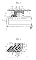
- Figure 1 shows a first embodiment of a rotation shaft seal relating to the present invention.
- the rotation shaft seal is attached between a housing 20 and a rotation shaft 10 (attached state) in the figure.
- a stopping ring 19 is fit to a concave peripheral groove formed on an inner peripheral face of the housing 20, and the rotation shaft seal is stopped by the stopping ring 19.
- the left side is a high-pressure side H where sealed fluid is stored, and the right side is a low-pressure side L.
- a mark 1 represents a seal element of resin such as PTFE and curving as an inner diameter side is in area contact with a peripheral face 11 of the rotation shaft 10 in the attached state. That is to say, the seal element 1 has an axis-orthogonal wall portion 2 at right angles with an axis X of the rotation shaft 10, a curved middle portion 3 continuing from an inner end of the axis-orthogonal wall portion 2 and curving toward the high-pressure side H, and a sealing lip portion 4 continuing from an end of the middle portion 3. And, a spiral groove 5 is formed on a sliding face of the sealing lip portion 4 on the rotation shaft 10.
- a mark 7 represents a supporting member of metal to hold the seal element 1.
- the supporting member 7 has a cylindrical peripheral wall portion 17 and a holding piece portion 18 protruding inward from an end portion of the cylindrical peripheral wall portion 17 on the low-pressure side L in diameter direction and having an approximately J-shaped cross section.
- the supporting member 7 is an outer case in this embodiment.
- the seal element 1, a gasket 40 of rubber or resin ring, and an inner case 21 (a holding member 8) having an inverted L-shaped cross section, are serially layered from the low-pressure side L to the high-pressure side H and fixed between an end edge 17a and the holding piece portion 18 by press-fitting of the end edge 17a of the peripheral wall portion 17 on the high-pressure side H.
- the gasket 40 may be disposed between the seal element 1 (the axis-orthogonal wall portion 2) and the supporting member 7.
- the seal element 1 is provided with a thin wall portion 6 formed by cutting the seal element 1 from the axis-orthogonal wall portion 2 to the middle portion 3 on the low-pressure side L.
- the sealing lip portion 4 is formed to be thick.
- the supporting member 7 is disposed as to contact the thin wall portion 6 on the low-pressure side L and having an R-shaped receiving face 9 to support the curved middle portion 3.
- the configuration of the receiving face 9, although not shown in figures, may be a bent face approximately right-angled, or a straight inclined face.
- Figure 2 shows a principal portion of the first embodiment shown in Figure 1.
- the supporting member 7 has a pressure-receiving face 16 to receive an inner-diameter face 15 of the middle portion 3, and a parallel face 16a, parallel to the peripheral face 11 of the rotation shaft 10, is formed on (the whole or a part of) the pressure-receiving face 16.
- the expression "parallel” is defined as to include approximate parallel in which the parallel face 16a slightly inclines against the peripheral face 11. It is preferable that the parallel face 16a is formed on the whole of the pressure-receiving face 16 and the parallel face 16a is disposed to be perfectly parallel to the peripheral face 11.
- the supporting member 7 has the pressure-receiving face 16 straight and continuing from the R-shaped receiving face 9, and the middle portion 3 (the thin wall portion 6) is supported by the R-shaped receiving face 9 and the straight pressure-receiving face 16 (the parallel face 16a).
- a total thickness dimension T in which a thickness dimension of the middle portion 3 (the thin wall portion 6) and a thickness dimension of the supporting member 7 from the receiving face 9 to the pressure-receiving face 16 are combined, is formed to be thinner than a thickness dimension t of the sealing lip portion 4.
- an end face 25 of the supporting member 7, supporting a back face (an end face on the low-pressure side L) of the sealing lip portion 4, is disposed at right angles with the axis X.
- Figure 3 shows a second embodiment of the present invention.
- the supporting member 7 of metal, holding the seal element 1 of resin such as PTFE, is an inner case fit to an outer case 22.
- the outer case 22 has an inner brim portion 24 on an end edge on the high-pressure side H, and a rubber sealing portion 23 is unitedly fixed to the peripheral face of the outer face 22 and the both of front and rear faces of the inner brim portion 24. Further, the seal element 1 is sandwiched between the supporting member 7 and the rubber sealing portion 23 by press fitting of an end edge 22a of the outer case 22 on the low-pressure side L.
- the supporting member 7 has a cylindrical peripheral wall portion 17 and a holding piece portion 18 protruding in an inward diameter direction from an end portion of the cylindrical peripheral wall portion 17 on the high-pressure side H and having an approximately J-shaped cross section.
- the seal element 1 is provided with a thin wall portion 6 formed by cutting the seal element 1 from the axis-orthogonal wall portion 2 to the middle portion 3 on the low-pressure side L. And, the supporting member 7 is disposed as to contact the thin wall portion 6 and having an R-shaped receiving face 9 to support the curved middle portion 3.
- Figure 4 shows a principal portion of the second embodiment.
- the supporting member 7 has a pressure-receiving face 16 to receive an inner-diameter face 15 of the middle portion 3, and the pressure-receiving face 16 has a parallel face 16a parallel to the peripheral face 11 of the rotation shaft 10.
- the supporting member 7 has the pressure-receiving face 16 straight and continuing from the R-shaped receiving face 9, and the middle portion 3 is supported by the R-shaped receiving face 9 and the straight pressure-receiving face 16 (the parallel face 16a).
- a total thickness dimension T in which a thickness dimension of the middle portion 3 and a thickness dimension of the supporting member 7 from the receiving face 9 to the pressure-receiving face 16 are combined, is formed to be thinner than a thickness dimension t of the sealing lip portion 4.
- Figure 5 shows a third embodiment of the present invention.
- the supporting member 7 of metal, holding the seal element 1 of resin such as PTFE, is an inner case fit to an outer case 22.
- a mark 22 represents the outer case having an inner brim portion 24 on an end edge on the high-pressure side H
- a mark 23 represents a rubber sealing portion unitedly fixed to the peripheral face of the outer face 22 and the both of front and rear faces of the inner brim portion 24.
- the supporting member 7, the seal element 1, a ring holding member 8, and the inner case 21 having an inverted L-shaped cross section are serially layered and fixed to the rubber sealing portion 23 by press fitting of an end edge 22a of the outer case 22 on the low-pressure side L.
- the supporting member 7 has a cylindrical peripheral wall portion 17 and a holding piece portion 18 protruding in an inward diameter direction from an end portion of the cylindrical peripheral wall portion 17 on the high-pressure side H and having an approximately J-shaped cross section.
- the seal element 1 is provided with a thin wall portion 6 formed by cutting the seal element 1 in a thickness direction from the axis-orthogonal wall portion 2 to the middle portion 3 on the low-pressure side L. And, the supporting member 7 is disposed as to contact the thin wall portion 6 and having an R-shaped receiving face 9 to support the curved middle portion 3.
- the supporting member 7 has a pressure-receiving face 16 to receive an inner-diameter face 15 of the middle portion 3, and the pressure-receiving face 16 has a parallel face 16a parallel to the peripheral face 11 of the rotation shaft 10. And, the supporting member 7 has the pressure-receiving face 16 straight and continuing from the R-shaped receiving face 9, and the middle portion 3 is received by the R-shaped receiving face 9 and the straight pressure-receiving face 16 (the parallel face 16a).
- a total thickness dimension T in which a thickness dimension of the middle portion 3 and a thickness dimension of the supporting member 7 from the receiving face 9 to the pressure-receiving face 16 are combined, is formed to be thinner than a thickness dimension t of the sealing lip portion 4.
- the rotation shaft seal as in the second embodiment and the third embodiment is preferable as a rotation shaft seal used for compressors on car air conditioners.
- Figure 7 shows a fourth embodiment of the present invention.
- the seal element 1 is held between a holding member 8 (of ring) on the high-pressure side H and a supporting member 7 (a holding piece portion 18) on the low-pressure side L (refer to Figure 5).
- the holding member 8 has an R-shaped pressing face 12 to contact the curved middle portion 3 on an inner end edge. That is to say, in the fourth embodiment in Figure 7, the holding member 8 in the third embodiment in Figures 5 and 6 is extended in inward diameter direction, and a corner portion on an inner end edge on the low-pressure side L is formed to be R-shaped along the curved face of the middle portion 3.
- the thickness dimension of the holding member 8 shown in Figure 7 is made large.
- an inner corner portion 13 to contact the seal element 1 (the peripheral face of the sealing lip portion 4) of the holding member 8 is disposed on a position which deviates from an end corner portion 14 to contact the middle portion 3 of the supporting member 7 in the axis X direction. That is to say, the inner corner portion 13 is disposed to deviate from the end corner portion 14 for an interval dimension A in the axis direction.
- the inner corner portion 13 is disposed on the position in contact with the peripheral face of the sealing lip portion 4 (with deviation from the end corner portion 14 in the axis X direction) to hold the sealing lip portion 4 from the peripheral side as the sealing lip portion 4 has stable area contact with the peripheral face 11 of the rotation shaft 10, and to preferably avoid stress concentration on contact portions of the inner corner portion 13 and the end corner portion 14 in pressure-receiving state.
- Figure 9 shows a sixth embodiment of the present invention in which the end (inner end) of the holding member 8 may be curved toward the high-pressure side H.
- an R-shaped pressing face 12 to contact the middle portion 3 is formed on the curved inner end edge of the holding member 8, and the inner corner portion 13 of the holding member 8 to contact the peripheral face of the sealing lip portion 4 is disposed on a position which deviates from the end corner portion 14 to contact the middle portion 3 of the supporting member 7 (for the interval dimension A in the axis direction) in the axis X direction.
- Figure 10 shows a seventh embodiment of the present invention.
- the seal element 1 is provided with a thin wall portion 6 formed by cutting the seal element 1 in thickness direction from the axis-orthogonal wall portion 2 to the middle portion 3 on the low-pressure side L and the high-pressure side H.
- the holding member 8 is disposed to contact a notched portion 26 on the high-pressure side H.
- the end edge of the holding member 8 has an R-shaped pressing face 12 to contact the middle portion 3, and the inner corner portion 13 to contact the notched portion 26 on the high-pressure side H is disposed on a position which deviates from the end corner portion 14 of the supporting member 7 (for the interval dimension A in the axis direction) in the axis X direction.
- the inner end edge (on the low-pressure side L) of the supporting member 7 may be formed into an angled shape.
- the inner end edge (on the low-pressure side L) of the supporting member 7 is formed R-shape. That is to say, the supporting member 7 is made by press working in Figures 1 through 10, and by cutting in Figure 11.
- the present invention may have two or more seal elements 1.
- the construction of the present invention may be applied to all of the seal elements 1.
- the thin wall portion 6 may be formed not on the axis-orthogonal wall portion 2 of the seal element 1 but on the middle portion 3 (by cutting) as to become gradually thinner toward the end.
- the supporting member 7 may be made of non-metal material. Production method can be one of ordinary methods such as press working (refer to Figures 1 through 10), cutting (refer to Figure 11), or forging when the supporting member 7 is made of metal. And, the thickness dimension of the supporting member 7 may be uniform, or formed (ununiformly) as to become thinner toward the end face 25 as shown in Figure 4.
- the groove formed on the sliding face of the sealing lip portion 4 may be composed of plural independent concentric grooves other than a spiral groove, and the groove may be omitted.
- a micro gap 30 is formed between the inner peripheral face of the supporting member 7 and the peripheral face 11 of the rotation shaft 10 in any of Figures 1 through 11.
- the middle portion 3 is received by the receiving face 9 in the pressure-receiving state in which the fluid pressure works.
- the curved configuration of the middle portion 3 before the pressure-receiving (in attached and unpressurized state) is kept by the (R-shaped) receiving face 9 also after the pressure-receiving.
- inward pressing force in diameter direction by the fluid pressure works near the connecting portion of the middle portion 3 and the sealing lip portion 4.
- the inner diameter face 15 of the middle portion 3 is held by the peripheral face 11 and the parallel face 16a (the pressure-receiving face 16).
- the portion near the connection of the middle portion 3 and the sealing lip portion 4 is held by the parallel face 16a (the pressure-receiving face 16) as to be parallel to the peripheral face 11, and the sliding face of the sealing lip portion 4 is pressed parallel to the peripheral face 11 (with uniform contact pressure) thereby.
- sealing lip portion 4 is pressed toward the low-pressure side L and supported by the end face 25 of the supporting member 7 as a staged face 31 formed by the cutting contacts the end face 25.
- the end face 25 of the supporting member 7 supports and prevents the sealing lip portion 4 from moving toward the low-pressure side L.
- the rotation shaft seal of the present invention is a rotation shaft seal provided with the seal element 1 having the axis-orthogonal wall portion 2 at right angles with the axis X, the curved middle portion 3 continuing from the inner end of the axis-orthogonal wall portion 2 and curving toward the high-pressure side H, and the sealing lip portion 4 continuing from the end of the middle portion 3, in which the seal element 1 is provided with the thin wall portion 6 on the middle portion 3, and the supporting member 7, having the receiving face 9 to contact the thin wall portion 6 from the low-pressure side L for supporting the middle portion 3, is provided.
- the middle portion 3 is prevented from being greatly deformed and pressed to the peripheral face 11 of the rotation shaft 10 because the middle portion 3 is received by the receiving face 9 in the pressure-receiving state. Therefore, bulging of the middle portion and local abrasion in conventional products (refer to Figure 13) are prevented, and good sealability is maintained for a long period of time. Further, contact pressure to the rotation shaft 10 is reduced, heat generation is restricted, and sliding torque is reduced.
- sealing lip portion 4 which tends to be abraded, can be easily modified to be thick.
- the thin wall portion 6 is easily formed because the thin wall portion 6 is formed by cutting the seal element 1 on the low-pressure side L in the thickness direction. And, the supporting member 7 is disposed within the cut portion, the sealing lip portion 4 (the staged face 31 on the low-pressure side L) is supported by the end face 25 of the supporting member 7, and the sealing lip portion 4 is prevented from moving toward the low-pressure side L to achieve good sealability.
- the thin wall portion 6 is easily formed because the thin wall portion 6 is formed by cutting the seal element 1 on the low-pressure side L in the thickness direction from the axis-orthogonal wall portion 2 to the middle portion 3. And, the supporting member 7 is disposed within the cut portion, the sealing lip portion 4 (the staged face 31 on the low-pressure side L) is supported by the end face 25 of the supporting member 7, and the sealing lip portion 4 is prevented from moving toward the low-pressure side L to achieve good sealability.
- the inner-diameter portion 15 of the middle portion 3 is received by the parallel face 16a to be parallel to the peripheral face 11 in the pressure-receiving state because the supporting member 7 has the pressure-receiving face 16 to receive the inner-diameter face 15 of the middle portion 3, and the parallel face 16a, parallel to the peripheral face 11 of the rotation shaft 10, is formed on the pressure-receiving face 16. That is to say, the portion near the connection of the middle portion 3 and the sealing lip portion 4 is held by the parallel face 16a as to be parallel to the peripheral face 11, and the sliding face of the sealing lip portion 4 is pressed parallel to the peripheral face 11 (to have area contact) thereby. Therefore, the contact pressure generated on the sliding face of the sealing lip portion 4 is made uniform and local abrasion of the sealing lip portion 4 is prevented to maintain the sealability for a long term.
- the sealing lip portion 4 certainly fits to the peripheral face 11 in the pressure-receiving state to achieve good sealability because the total thickness dimension T, which is composed of the thickness dimension of the middle portion 3 and the thickness dimension from the R-shaped receiving face 9 to the pressure-receiving face 16 of the supporting member 7, is formed to be thinner than the thickness dimension t of the sealing lip portion 4.
- the curved configuration of the middle portion before pressurization is certainly kept after the pressurization to achieve good sealability because the holding member 8, disposed on the high-pressure side H of the seal element 1 and holding the seal element 1 with the supporting member 7, is provided, and the R-shaped pressing face 12 to contact the middle portion 3 is formed on the inner end edge of the holding member 8.
Landscapes
- Engineering & Computer Science (AREA)
- General Engineering & Computer Science (AREA)
- Mechanical Engineering (AREA)
- Physics & Mathematics (AREA)
- Fluid Mechanics (AREA)
- Sealing With Elastic Sealing Lips (AREA)
- Sealing Devices (AREA)
Applications Claiming Priority (1)
| Application Number | Priority Date | Filing Date | Title |
|---|---|---|---|
| JP2006250733A JP4800158B2 (ja) | 2006-09-15 | 2006-09-15 | 回転軸シール |
Publications (1)
| Publication Number | Publication Date |
|---|---|
| EP1900982A1 true EP1900982A1 (de) | 2008-03-19 |
Family
ID=38698448
Family Applications (1)
| Application Number | Title | Priority Date | Filing Date |
|---|---|---|---|
| EP07014593A Withdrawn EP1900982A1 (de) | 2006-09-15 | 2007-07-25 | Wellendichtung |
Country Status (4)
| Country | Link |
|---|---|
| US (1) | US20080067759A1 (de) |
| EP (1) | EP1900982A1 (de) |
| JP (1) | JP4800158B2 (de) |
| KR (1) | KR101368294B1 (de) |
Cited By (2)
| Publication number | Priority date | Publication date | Assignee | Title |
|---|---|---|---|---|
| US20150042044A1 (en) * | 2013-08-05 | 2015-02-12 | Aktiebolaget Skf | Sealing assembly |
| CN109477577A (zh) * | 2016-05-20 | 2019-03-15 | 特瑞堡密封系统德国有限公司 | 具有压力可激活旋转密封件的旋转密封件组合件和旋转密封件 |
Families Citing this family (8)
| Publication number | Priority date | Publication date | Assignee | Title |
|---|---|---|---|---|
| WO2010113006A1 (en) * | 2009-03-30 | 2010-10-07 | Saint-Gobain Performance Plastics Pampus Gmbh | Seal ring for exhaust gas recirculation system |
| JP2012097706A (ja) * | 2010-11-05 | 2012-05-24 | Hitachi Automotive Systems Ltd | 可変動弁装置のアクチュエータ |
| JP5726345B1 (ja) | 2014-03-24 | 2015-05-27 | 三菱電線工業株式会社 | 軸シール |
| JP5657824B1 (ja) * | 2014-05-20 | 2015-01-21 | 三菱電線工業株式会社 | 軸シール |
| DE102017011117B4 (de) * | 2017-12-01 | 2020-08-13 | Carl Freudenberg Kg | Dichtring und Dichtungsanordnung, die einen solchen Dichtring umfasst |
| JP7530705B2 (ja) * | 2019-04-17 | 2024-08-08 | ナブテスコ株式会社 | シール構造 |
| IT201900015647A1 (it) * | 2019-09-05 | 2021-03-05 | Skf Ab | Dispositivo di tenuta per gruppo mozzo-ruota |
| CN112833101A (zh) * | 2021-01-18 | 2021-05-25 | 舍弗勒技术股份两合公司 | 轴承及密封装置 |
Citations (5)
| Publication number | Priority date | Publication date | Assignee | Title |
|---|---|---|---|---|
| US2213116A (en) * | 1939-01-28 | 1940-08-27 | Victor Mfg & Gasket Co | Flexible oil seal |
| US2630357A (en) * | 1950-03-22 | 1953-03-03 | Garlock Packing Co | Packing element with rigid mounting and reinforcing member |
| JP2003194231A (ja) | 2001-12-28 | 2003-07-09 | Mitsubishi Cable Ind Ltd | 回転軸シール |
| WO2003062681A1 (en) * | 2001-12-28 | 2003-07-31 | Mitsubishi Cable Industries, Ltd. | Seal for rotating shaft and method for manufacture thereof |
| EP1598579A1 (de) * | 2003-02-27 | 2005-11-23 | EAGLE INDUSTRY Co., Ltd. | Lippendichtung |
Family Cites Families (36)
| Publication number | Priority date | Publication date | Assignee | Title |
|---|---|---|---|---|
| US2264148A (en) * | 1940-06-06 | 1941-11-25 | Garlock Packing Co | Machinery packing |
| US2264970A (en) * | 1940-06-07 | 1941-12-02 | Garlock Packing Co | Machinery packing |
| US2447411A (en) * | 1945-07-05 | 1948-08-17 | Nat Motor Bearing Co Inc | Fluid seal |
| US2466533A (en) * | 1947-04-08 | 1949-04-05 | Garlock Packing Co | Oil seal |
| US2804324A (en) * | 1953-09-11 | 1957-08-27 | Gen Motors Corp | Seal |
| US2950135A (en) * | 1956-09-07 | 1960-08-23 | Chicago Rawhide Mfg Co | Oil seal |
| JPS348017Y1 (de) * | 1957-03-11 | 1959-05-27 | ||
| US3362719A (en) * | 1965-10-23 | 1968-01-09 | Ramsey Corp | Inserts for rotary shaft seals |
| US3383145A (en) * | 1966-08-19 | 1968-05-14 | Hennessy Lubricator Co Inc | Railway journal dust guard seal |
| JPS4982151U (de) * | 1972-11-04 | 1974-07-16 | ||
| US3902726A (en) * | 1974-03-15 | 1975-09-02 | Chuetsu Waukesha Co Ltd | Stern tube sealing device |
| JPS5354651A (en) * | 1976-10-27 | 1978-05-18 | Nippon Oil Seal Ind Co Ltd | Oil seal and method of making same |
| JPS58128569A (ja) * | 1982-01-26 | 1983-08-01 | Akira Washida | シ−ル |
| US4440405A (en) * | 1982-09-29 | 1984-04-03 | Dana Corporation | Hydrodynamic shaft seal with continuously divergent seal element |
| US4755115A (en) * | 1984-11-21 | 1988-07-05 | Atsugi Motor Parts Company, Limited | Shaft seal assembly for compressor |
| DE3524461A1 (de) * | 1985-07-09 | 1987-01-22 | Kaco Gmbh Co | Radialwellendichtring |
| JPS6267372A (ja) * | 1985-09-17 | 1987-03-27 | Nok Corp | オイルシ−ルおよびその製造方法 |
| JPH0332843Y2 (de) * | 1987-03-27 | 1991-07-11 | ||
| US4834397A (en) * | 1988-05-20 | 1989-05-30 | Taiho Kogyo Co., Ltd. | Lip seal device having an annular groove |
| JPH01169669U (de) * | 1988-05-23 | 1989-11-30 | ||
| DE9213373U1 (de) * | 1992-10-05 | 1994-02-10 | Martin Merkel GmbH & Co KG, 21107 Hamburg | Wellendichtring mit einer Dichtlippe |
| JPH06159519A (ja) * | 1992-11-18 | 1994-06-07 | Mitsubishi Cable Ind Ltd | 回転軸シール |
| DE19501724C1 (de) * | 1995-01-20 | 1996-10-10 | Bruss Dichtungstechnik | Wellendichtring sowie Verfahren und Vorrichtung zu seiner Herstellung |
| JPH08303603A (ja) * | 1995-04-28 | 1996-11-22 | Nok Corp | 密封装置 |
| DE19642544A1 (de) * | 1996-10-15 | 1998-04-23 | Bruss Dichtungstechnik | Radialwellendichtring mit PTFE-Dichtlippe und Verfahren sowie Vorrichtung zu dessen Herstellung |
| US6149158A (en) * | 1998-06-30 | 2000-11-21 | Federal-Mogul World Wide, Inc. | Unitized oil seal with PTFE sealing disk split at radially outer edge and method of manufacture |
| US6367811B1 (en) * | 1998-11-24 | 2002-04-09 | Mitsubishi Cable Industries, Ltd. | Rotation shaft seal |
| JP2001263499A (ja) * | 2000-03-17 | 2001-09-26 | Eagle Ind Co Ltd | リップ型シール |
| JP2003097723A (ja) * | 2001-09-25 | 2003-04-03 | Mitsubishi Cable Ind Ltd | 回転軸シール |
| JP2003120823A (ja) * | 2001-10-19 | 2003-04-23 | Eagle Ind Co Ltd | シール装置 |
| JP2003176872A (ja) * | 2001-12-10 | 2003-06-27 | Toyota Industries Corp | 軸封装置及びその組み付け方法 |
| JP2004183799A (ja) * | 2002-12-04 | 2004-07-02 | Kayaba Ind Co Ltd | 摺動部のシール構造 |
| DE10313958A1 (de) * | 2003-03-27 | 2004-10-28 | Carl Freudenberg Kg | Dichtring |
| US7134670B2 (en) * | 2003-05-29 | 2006-11-14 | Mitsubishi Cable Industries, Ltd. | Rotation shaft seal |
| JP2005042881A (ja) * | 2003-07-25 | 2005-02-17 | Denso Corp | リップ型シールによる軸封構造 |
| JP2005337422A (ja) * | 2004-05-28 | 2005-12-08 | Kayaba Ind Co Ltd | パッキン |
-
2006
- 2006-09-15 JP JP2006250733A patent/JP4800158B2/ja not_active Expired - Fee Related
-
2007
- 2007-07-09 KR KR1020070068657A patent/KR101368294B1/ko not_active Expired - Fee Related
- 2007-07-25 EP EP07014593A patent/EP1900982A1/de not_active Withdrawn
- 2007-08-06 US US11/882,790 patent/US20080067759A1/en not_active Abandoned
Patent Citations (5)
| Publication number | Priority date | Publication date | Assignee | Title |
|---|---|---|---|---|
| US2213116A (en) * | 1939-01-28 | 1940-08-27 | Victor Mfg & Gasket Co | Flexible oil seal |
| US2630357A (en) * | 1950-03-22 | 1953-03-03 | Garlock Packing Co | Packing element with rigid mounting and reinforcing member |
| JP2003194231A (ja) | 2001-12-28 | 2003-07-09 | Mitsubishi Cable Ind Ltd | 回転軸シール |
| WO2003062681A1 (en) * | 2001-12-28 | 2003-07-31 | Mitsubishi Cable Industries, Ltd. | Seal for rotating shaft and method for manufacture thereof |
| EP1598579A1 (de) * | 2003-02-27 | 2005-11-23 | EAGLE INDUSTRY Co., Ltd. | Lippendichtung |
Cited By (5)
| Publication number | Priority date | Publication date | Assignee | Title |
|---|---|---|---|---|
| US20150042044A1 (en) * | 2013-08-05 | 2015-02-12 | Aktiebolaget Skf | Sealing assembly |
| US9410555B2 (en) * | 2013-08-05 | 2016-08-09 | Aktiebolaget Skf | Sealing assembly |
| CN109477577A (zh) * | 2016-05-20 | 2019-03-15 | 特瑞堡密封系统德国有限公司 | 具有压力可激活旋转密封件的旋转密封件组合件和旋转密封件 |
| CN109477577B (zh) * | 2016-05-20 | 2020-12-08 | 特瑞堡密封系统德国有限公司 | 具有压力可激活旋转密封件的旋转密封件组合件和旋转密封件 |
| US11512778B2 (en) | 2016-05-20 | 2022-11-29 | Trelleborg Sealing Solutions Germany Gmbh | Pressure-activatable rotary seal and rotary seal assembly |
Also Published As
| Publication number | Publication date |
|---|---|
| US20080067759A1 (en) | 2008-03-20 |
| JP2008069909A (ja) | 2008-03-27 |
| JP4800158B2 (ja) | 2011-10-26 |
| KR20080025287A (ko) | 2008-03-20 |
| KR101368294B1 (ko) | 2014-02-26 |
Similar Documents
| Publication | Publication Date | Title |
|---|---|---|
| EP1900982A1 (de) | Wellendichtung | |
| EP2053287A1 (de) | Wellendichtung | |
| JP5710053B2 (ja) | シール装置 | |
| EP2924325B1 (de) | Wellendichtung | |
| CN100396974C (zh) | 唇型密封装置 | |
| EP2551563B1 (de) | Dichtung für eine drehwelle | |
| EP1944534B1 (de) | Wellendichtung | |
| EP1146265A2 (de) | Wellendichtung | |
| EP2947356A1 (de) | Wellendichtung | |
| EP1760371A1 (de) | Dichtungsvorrichtung | |
| KR101331248B1 (ko) | 메카니컬 실링장치 | |
| US7722052B2 (en) | Rotation shaft seal | |
| KR20140015335A (ko) | 밀봉링 | |
| EP2924324B1 (de) | Wellendichtung | |
| US12313164B2 (en) | Sealing device | |
| US20190049018A1 (en) | Seal ring | |
| CN217813922U (zh) | 一种涡旋压缩机的泵体结构和压缩机 | |
| JP7124057B2 (ja) | シール装置 | |
| JP2001074144A (ja) | 回転軸シール | |
| JP2005155471A (ja) | 圧縮機におけるシール構造 |
Legal Events
| Date | Code | Title | Description |
|---|---|---|---|
| PUAI | Public reference made under article 153(3) epc to a published international application that has entered the european phase |
Free format text: ORIGINAL CODE: 0009012 |
|
| AK | Designated contracting states |
Kind code of ref document: A1 Designated state(s): AT BE BG CH CY CZ DE DK EE ES FI FR GB GR HU IE IS IT LI LT LU LV MC MT NL PL PT RO SE SI SK TR |
|
| AX | Request for extension of the european patent |
Extension state: AL BA HR MK YU |
|
| 17P | Request for examination filed |
Effective date: 20080718 |
|
| 17Q | First examination report despatched |
Effective date: 20080825 |
|
| AKX | Designation fees paid |
Designated state(s): DE FR GB |
|
| STAA | Information on the status of an ep patent application or granted ep patent |
Free format text: STATUS: THE APPLICATION IS DEEMED TO BE WITHDRAWN |
|
| 18D | Application deemed to be withdrawn |
Effective date: 20090108 |