EP1900974A1 - Pommeau de levier de commande de bôite de vitesses avec interface utilisateur - Google Patents
Pommeau de levier de commande de bôite de vitesses avec interface utilisateur Download PDFInfo
- Publication number
- EP1900974A1 EP1900974A1 EP20060120686 EP06120686A EP1900974A1 EP 1900974 A1 EP1900974 A1 EP 1900974A1 EP 20060120686 EP20060120686 EP 20060120686 EP 06120686 A EP06120686 A EP 06120686A EP 1900974 A1 EP1900974 A1 EP 1900974A1
- Authority
- EP
- European Patent Office
- Prior art keywords
- function
- driving
- functions
- assistant
- status
- Prior art date
- Legal status (The legal status is an assumption and is not a legal conclusion. Google has not performed a legal analysis and makes no representation as to the accuracy of the status listed.)
- Withdrawn
Links
- 230000005540 biological transmission Effects 0.000 title description 2
- 239000000725 suspension Substances 0.000 claims description 10
- 230000033228 biological regulation Effects 0.000 claims description 6
- 230000003044 adaptive effect Effects 0.000 claims description 3
- 230000014759 maintenance of location Effects 0.000 claims description 3
- 230000008859 change Effects 0.000 description 7
- 230000009471 action Effects 0.000 description 4
- 230000003213 activating effect Effects 0.000 description 2
- 238000010586 diagram Methods 0.000 description 2
- 230000009191 jumping Effects 0.000 description 2
- 230000007935 neutral effect Effects 0.000 description 2
- 230000004913 activation Effects 0.000 description 1
- 230000003190 augmentative effect Effects 0.000 description 1
- 230000001427 coherent effect Effects 0.000 description 1
- 230000006835 compression Effects 0.000 description 1
- 238000007906 compression Methods 0.000 description 1
- 238000012790 confirmation Methods 0.000 description 1
- 230000003247 decreasing effect Effects 0.000 description 1
- 230000000694 effects Effects 0.000 description 1
- 238000012986 modification Methods 0.000 description 1
- 230000004048 modification Effects 0.000 description 1
- 230000003068 static effect Effects 0.000 description 1
- 230000000007 visual effect Effects 0.000 description 1
- 238000012800 visualization Methods 0.000 description 1
Images


Classifications
-
- B60K35/10—
-
- B—PERFORMING OPERATIONS; TRANSPORTING
- B60—VEHICLES IN GENERAL
- B60K—ARRANGEMENT OR MOUNTING OF PROPULSION UNITS OR OF TRANSMISSIONS IN VEHICLES; ARRANGEMENT OR MOUNTING OF PLURAL DIVERSE PRIME-MOVERS IN VEHICLES; AUXILIARY DRIVES FOR VEHICLES; INSTRUMENTATION OR DASHBOARDS FOR VEHICLES; ARRANGEMENTS IN CONNECTION WITH COOLING, AIR INTAKE, GAS EXHAUST OR FUEL SUPPLY OF PROPULSION UNITS IN VEHICLES
- B60K20/00—Arrangement or mounting of change-speed gearing control devices in vehicles
- B60K20/02—Arrangement or mounting of change-speed gearing control devices in vehicles of initiating means
-
- B—PERFORMING OPERATIONS; TRANSPORTING
- B60—VEHICLES IN GENERAL
- B60K—ARRANGEMENT OR MOUNTING OF PROPULSION UNITS OR OF TRANSMISSIONS IN VEHICLES; ARRANGEMENT OR MOUNTING OF PLURAL DIVERSE PRIME-MOVERS IN VEHICLES; AUXILIARY DRIVES FOR VEHICLES; INSTRUMENTATION OR DASHBOARDS FOR VEHICLES; ARRANGEMENTS IN CONNECTION WITH COOLING, AIR INTAKE, GAS EXHAUST OR FUEL SUPPLY OF PROPULSION UNITS IN VEHICLES
- B60K35/00—Arrangement of adaptations of instruments
-
- F—MECHANICAL ENGINEERING; LIGHTING; HEATING; WEAPONS; BLASTING
- F16—ENGINEERING ELEMENTS AND UNITS; GENERAL MEASURES FOR PRODUCING AND MAINTAINING EFFECTIVE FUNCTIONING OF MACHINES OR INSTALLATIONS; THERMAL INSULATION IN GENERAL
- F16H—GEARING
- F16H59/00—Control inputs to control units of change-speed-, or reversing-gearings for conveying rotary motion
- F16H59/02—Selector apparatus
- F16H59/0217—Selector apparatus with electric switches or sensors not for gear or range selection, e.g. for controlling auxiliary devices
-
- B60K2360/113—
-
- B60K2360/117—
-
- B60K2360/143—
-
- B60K2360/1438—
Definitions
- the present invention relates to a driving assistant for controlling and/or adjusting functions related to driving, such as for example changing gear, driving mode, suspensions adjustment, etc. This is carried out by an operating device that allows the user at least browsing and selecting one or more functions.
- a output means is also provided such as for example a display means for displaying information about at least the selected function.
- Known solutions for controlling several functions in a motor vehicle are for example the one disclosed in DE10207872 which refers to a device for selecting information from a menu structure and controlling a screen display. It comprises a joystick lever that pivots about its longitudinal axis for menu selection highlighting the field on the display.
- the joystick has a rotating and clicking top button and it has a start position and it can be moved with two degrees of freedom relative to this point. An additional movement of the activation member enables the menu to be reset to its highest menu layer.
- An object of the present invention is to provide a driving assistant for controlling functions, for example functions related to driving, or other functions, in a motor vehicle, in such a way that controlling of said functions by the user is easy.
- Such control through the driving assistant of the invention can be carried out during driving or at any other given time.
- the user can control functions such as for example a driving mode (4x4, etc) while driving but the user can also control functions such as for example mirror adjustment before driving.
- functions related to driving refers to those functions associated with a motor vehicle that affect its behaviour, such as for example changing gear, either in automatic (park, reverse, neutral, drive) or manual or sequential mode.
- driving related functions include driving modes (sport, city, etc.), suspension adjustments (stiffness, height), etc.
- the driving assistant of the invention can control functions other than driving related functions.
- Said other functions may for example comprise at least a comfort function (air conditioner, etc) or at least a multimedia function (radio, CD, display).
- driving assistant of the invention is particularly addressed to control functions related to driving, it is not intended to be limited to these functions but it may be used for controlling another type of functions, such as for example for controlling multimedia devices or a vehicle air conditioner system.
- the driving assistant of the invention comprises an operating device for at least browsing and selecting one or more functions.
- this gearshift command is suitable for further setting a corresponding status of said function.
- the user can browse a menu for selecting a function.
- the function can be merely left selected or, in addition, the status of the selected function can be set. In some cases, the status can be set only by selecting that function, i.e. simply by focusing the target function.
- that function status remains unchanged save as otherwise changed by the user.
- an user browsing the menu through the gearshift command selects a driving mode from Winter/Sport/City by focussing one option e.g. in a vertical menu.
- the user can change the status of the function selected (enabling or disabling said function).
- the status of said function can be set either by using the same gearshift command or using another separate command (for example a switch, joystick or other suitable command).
- the function status is set when the function is focussed in the menu by the command.
- the last function status selected remains unchanged while it is not set again by the user.
- the status of the selected function may be an on/off status and/or an adjustable status.
- on/off status of a function is ESP (Electronic Stability Program), driving modes (sport, city, winter).
- Examples of adjustable status of a function is suspension adjustment, etc. in which user can adjust parameters all along an allowed range. In both cases, the selection would not require a confirmation action.
- the option is selected with up, down, left, right movements thereof (optionally in conjunction with locking means as explained hereinbelow and the option becomes active.
- the operating device is the gearshift command (usually the gearshift lever) of the motor vehicle, so that with the same gearshift lever, at least a function related to driving may be controlled, including the gear change.
- output means for giving feedback to the user.
- This feedback may be visual (a display means), audible (sound), vibration, haptic, or other.
- the output means is for example a display means, it sends information through a menu about at least a function that the user has been selected by the gearshift lever.
- the menu in the display means shows different functions the user is allowed to enable, disable and/or adjust.
- the displaying means may comprise a dedicated display or an existing vehicle display. In any case, the display may be for example a touch screen or a head-up display. Additional information could be provided to the user related to the selected function to enrich the user with augmented reality, camera visualization, proximity sensors, or any other related functions.
- the gearshift lever is a shift by wire type gearshift lever and it may be in the form of a joystick.
- the operating device may comprise a number of sensors associated to a logic control communicating with elements of the motor vehicle which respond upon operation of the gearshift lever. These sensors deals either with signals related to driving or any other type of signals.
- the lever is displaceable from one single stable position (when not operated) to at least one unstable position, typically four: up, down, right, left, for said control operations.
- the lever automatically returns to its stable position as it is released.
- the operating device may be provided with locking means for enabling or disabling operation of functions.
- This locking means may be in the form of a push button fitted on the gearshift lever knob. Locking means may alternatively enable or disable functions by software. In this way, functions may be controlled according to different criteria, such as for example depending upon vehicle conditions (speed, open/closed door status, etc.)
- the main function of the driving assistant of the invention remains the gear change (whether the user is browsing within the options menu or not).
- a movement of the joystick lever (optionally in conjunction with the locking means) to one direction would cause the operation mode returns back to the automatic gear change mode.
- a movement of the joystick lever to another direction would cause the operation mode return back to function control.
- a reset function would permit any previously selected option to be deleted thus simplifying the task of returning to a normal driving mode.
- the driving assistant communicates bidirectionally with the motor vehicle for sending some commands to a receiving system (operating reverse gear, activating ASR, etc%), as well as receiving information about the state of the vehicle (speed, brake pedal) which will be used for enabling or disabling some of the functions as appropriate according to safety or reliability criteria.
- the driving assistant of the invention comprises an operating device such as a gearshift lever 100 of a motor vehicle.
- the gearshift lever 100 may be for example a shift by wire type gearshift lever.
- Lever 100 permits the user at least browsing and selecting one or several of functions. A corresponding status of said function can be also set. At least one of such functions is a function related to driving.
- the driving assistant of the invention further includes output means for giving feedback to the user.
- the output means is a display means such a touch screen displaying information about at least the selected function as shown in figs 4 and 5 of the drawings.
- Lever 100 may be provided with locking means 110 for enabling or disabling operation of functions.
- the status of a function that is to be selected by the lever 100 may be an on/off status or an adjustable status.
- Such functions may be selected from the group consisting of direct vehicle dynamic control [shifter -atx, sequential-, (adaptive) cruise control, retention/parking assistant, lane keeping assistant, parallel parking assistant], operational modes [traction mode, 4x4, ESP, pre-crash brake assist], and regulations [suspension regulation -stiffness, height-, mirror adjustment, seat adjustment, steering wheel position adjustment].
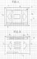
- the operating device (selector lever 100) comprises a lower follower finger 120 which may be displaced axially relative to the lever 100 and a compression spring 130 arranged outside and around the lever 100 such that the follower finger 120 is urged downwardly against a contoured surface 140 arranged at the bottom of the device in such a way that the selector lever tip 101 is always substantially in contact with said contoured surface 140.
- the operating device further includes emitting and receiving means for detecting the position of the selector lever tip 101 on the contoured surface 140.
- the receiving means comprise an electronic board 150 fitted below the contoured surface 140, at the bottom thereof.
- the electronic board 150 is provided with a series of sensors 160 arranged at the bottom thereof and associated to a logic control which communicates with elements of the motor vehicle (suspensions, transmission, etc) which respond upon operation of the gearshift lever 100.
- the lever 100 In order the user operates the lever 100, the lever 100 is displaceable from one stable position, which is normally a central position, i.e. with the lever 100 in a upright position, to at least one unstable position.
- the term "unstable” as used herein means a position reached when the user moves the lever 100 from that central, stable position, and when the lever 100 is then released, it returns back to said stable position.
- Command may comprise the shift by wire gearshift joystick lever assembly 100 shown in fig. 3 having sensors 160 outputting an electric signal to a logic 3.
- the lever assembly 100 may have static feedback 2a (feeling) or dynamic, controlled through a force-feedback actuator which dynamically varies the force.
- Logic 3 implements the machine main state, or logic of the system. It takes as a main input the position 2 of the joystick lever 100 (and enable button 110), and also some critical information from the vehicle 4a such as vehicle speed or brake pedal pressed. It computes the command to be sent to electronic control units 4 (ECUs) for executing a request 4b (move to drive position, disable ESP, etc).
- ECUs electronice control units 4
- a display device 5 shows the current status and the information 5a of the possible functions to be done by the driver. Audio messages could also be used as an additional feedback to the driver.
- the driving assistant is initially in a shifter function mode SHT.
- a left tip L or right tip R of the lever will change the function.
- a left tip L of the lever will sequentially enable one function after another.
- a single right tip R of the lever will return to the shifter mode SHT again, regardless of the mode or function. This increases the availability of the most critical function, the shifter, making the system safer.
- An up tip U of the lever or a down tip D of the lever will enable different options within a function.
- Modes such as drive modes DM
- modes are mono-stable, that is, they are active only when a lever tip is performed, returning back to a previous position. This is for example the case of the up gear or the speed decrease.
- the user can go from down position D (optionally also from S position) to manual mode M with a right tip R.
- Some other modes use time to change repeatedly. Speed is increased in a fixed amount either when doing a tip lever, or once per second when keeping it pressed.
- Menu in the display 5 as shown in figs. 4 and 5 can be browsed by the user for selecting a function using the gearshift command 100.
- the desired function has been selected by being focussed on the menu by the command 100, its status (on/off/adjust) may be in some cases automatically set. In other cases, the status of the selected function is set either by acting on the gearshift lever 100 or using another separate command (for example a switch, joystick or other suitable command).
- another separate command for example a switch, joystick or other suitable command.
- the example of the display device 5 diagrammatically shown in fig. 4 displays the user a menu list 6 and menu options 7.
- Menu options 7 can be scrolled either to left 7a and right 7b in the display menu.
- the status of the selected function is displayed on a display box 8, for example, ESP, driving mode, current gear, etc.
- Display device 5 may show other additional information, a logo 9, etc.
- FIG. 5 One example a of said status is diagrammatic shown in fig. 5.
- the display has an attractive appearance which may be configured as desired.
- the upper portion of the display menu shows different available functions 10 (e.g. ESP, the user and the selected function 10a, for example suspensions, driving mode, etc) and the currently selected function 10a.
- the state of any function may be logged. There would be an initial status as a default state (e.g. cruise control/off), but if default state is changed, whenever the user quit and go back from that function, last state will be restored (e.g. a city mode is active and the user goes back to the shifter mode and then again to drive modes; the state within drive modes is still city mode.
- a default state e.g. cruise control/off
- last state e.g. a city mode is active and the user goes back to the shifter mode and then again to drive modes; the state within drive modes is still city mode.
- cruise control CC in which initial state is off, and it can be enabled by the driver, but it will be disabled any time the driver changes the function. Also, in this mode, cruise control CC will be automatically disabled if an action in the brake pedal of the vehicle, or other driver actions, is carried out, as in most cars having this function.
- the display means 5 show the user information about whether the enable button E is pressed, or the brake pedal BP is pressed, the vehicle Speed SP.
- Function list may be, for example, circular to the left, i.e., a left tip L in the last function (driving modes DM) will go to the second function (cruise control CC). There is no need for going to the first function (shifter SHT) because this is always available in one right tip R.
- Function order is a critical parameter.
Priority Applications (5)
| Application Number | Priority Date | Filing Date | Title |
|---|---|---|---|
| EP20060120686 EP1900974A1 (fr) | 2006-09-14 | 2006-09-14 | Pommeau de levier de commande de bôite de vitesses avec interface utilisateur |
| US12/441,348 US9139094B2 (en) | 2006-09-14 | 2007-09-12 | Transmission control lever with user interface |
| DE200711002128 DE112007002128T5 (de) | 2006-09-14 | 2007-09-12 | Fahrassistenzvorrichtung |
| PCT/EP2007/059604 WO2008031858A1 (fr) | 2006-09-14 | 2007-09-12 | Levier de commande de transmission à interface utilisateur |
| JP2009527823A JP5653039B2 (ja) | 2006-09-14 | 2007-09-12 | ユーザーインターフェースを有する変速制御レバー |
Applications Claiming Priority (1)
| Application Number | Priority Date | Filing Date | Title |
|---|---|---|---|
| EP20060120686 EP1900974A1 (fr) | 2006-09-14 | 2006-09-14 | Pommeau de levier de commande de bôite de vitesses avec interface utilisateur |
Publications (1)
| Publication Number | Publication Date |
|---|---|
| EP1900974A1 true EP1900974A1 (fr) | 2008-03-19 |
Family
ID=37717611
Family Applications (1)
| Application Number | Title | Priority Date | Filing Date |
|---|---|---|---|
| EP20060120686 Withdrawn EP1900974A1 (fr) | 2006-09-14 | 2006-09-14 | Pommeau de levier de commande de bôite de vitesses avec interface utilisateur |
Country Status (5)
| Country | Link |
|---|---|
| US (1) | US9139094B2 (fr) |
| EP (1) | EP1900974A1 (fr) |
| JP (1) | JP5653039B2 (fr) |
| DE (1) | DE112007002128T5 (fr) |
| WO (1) | WO2008031858A1 (fr) |
Cited By (7)
| Publication number | Priority date | Publication date | Assignee | Title |
|---|---|---|---|---|
| WO2009138145A1 (fr) * | 2008-05-10 | 2009-11-19 | Wabco Gmbh | Dispositif transmetteur pour système de changement de vitesses |
| DE102009038427A1 (de) * | 2009-08-21 | 2011-02-24 | Bayerische Motoren Werke Aktiengesellschaft | Bedienelement |
| CN103574005A (zh) * | 2012-07-19 | 2014-02-12 | Sl株式会社 | 汽车变速器 |
| WO2016151457A1 (fr) * | 2015-03-20 | 2016-09-29 | Iveco S.P.A. | Système de sélection d'un mode de traction de véhicule d'un véhicule hybride ou multimode |
| DE102016003012A1 (de) | 2016-03-12 | 2017-09-14 | Audi Ag | Wählhebelvorrichtung für ein Kraftfahrzeug |
| DE102008018279B4 (de) | 2007-04-13 | 2019-04-04 | GM Global Technology Operations LLC (n. d. Ges. d. Staates Delaware) | System und verfahren zur verwaltung interner komponenten eines fahrzeugs über eine insassenüberwachung |
| CN111878574A (zh) * | 2020-06-30 | 2020-11-03 | 东风汽车集团有限公司 | 一种电子换挡机构的防误触发方法及系统 |
Families Citing this family (13)
| Publication number | Priority date | Publication date | Assignee | Title |
|---|---|---|---|---|
| DE102008001805A1 (de) * | 2008-05-15 | 2009-11-19 | Zf Friedrichshafen Ag | Betätigungseinrichtung mit Force Feedback |
| US8554440B1 (en) * | 2010-01-05 | 2013-10-08 | Davis Intellectual Properties LLC | Electronic traction control |
| US8132844B2 (en) * | 2010-02-25 | 2012-03-13 | Trimark Corporation | Intuitive control system for power assisted vehicle doors |
| DE102010024388B4 (de) | 2010-06-19 | 2012-12-06 | Audi Ag | Vorrichtung zur Bedienung von Funktionen eines Kraftfahrzeugs |
| DE102010032774A1 (de) * | 2010-07-29 | 2012-02-02 | Rainer Petzold | Fahrschalter |
| US8725368B2 (en) * | 2010-10-13 | 2014-05-13 | GM Global Technology Operations LLC | Rocking enabled shift-by-wire system |
| US9383000B2 (en) * | 2011-11-11 | 2016-07-05 | Volkswagen Ag | Gearshift knob and method for operating a vehicle |
| FR3005934B1 (fr) * | 2013-05-23 | 2015-05-01 | Airbus Operations Sas | Systeme et procede de commande d’un aeronef |
| KR102227397B1 (ko) * | 2014-09-22 | 2021-03-15 | 에스엘 주식회사 | 차량용 통합 제어 시스템 및 그 제어 방법 |
| DE102014226014A1 (de) * | 2014-12-16 | 2016-06-16 | Volkswagen Aktiengesellschaft | Bedienvorrichtung und Verfahren zum Bedienen eines Parkassistenzsystems eines Kraftfahrzeugs |
| DE102016200029A1 (de) * | 2016-01-05 | 2017-07-06 | Zf Friedrichshafen Ag | Betätigungsvorrichtung für ein Schalten durch eine Drahtbaugruppe |
| US10253872B2 (en) | 2016-04-22 | 2019-04-09 | Ford Global Technologies, Llc | Driver interface |
| DE102016217145B4 (de) | 2016-09-08 | 2021-08-12 | Volkswagen Aktiengesellschaft | Bedienungsanordnung, Hybridantriebsanordnung und Fahrzeug |
Citations (12)
| Publication number | Priority date | Publication date | Assignee | Title |
|---|---|---|---|---|
| FR2071184A5 (fr) * | 1969-12-19 | 1971-09-17 | Balzac Max | |
| DE3901649A1 (de) * | 1989-01-20 | 1990-08-02 | Kloeckner Humboldt Deutz Ag | Vorrichtung zum steuern eines landwirtschaftlichen fahrzeugs |
| DE4120975A1 (de) * | 1991-06-25 | 1993-01-07 | Vdo Schindling | Bedienungsvorrichtung fuer eine anzeigeeinrichtung |
| WO1994026549A1 (fr) * | 1993-05-06 | 1994-11-24 | Armando Iannice | Organe de commande compact pour vehicules a moteurs, en particulier des camions |
| EP0629526A1 (fr) * | 1993-06-16 | 1994-12-21 | Silvano Di Francesco | Unité de manette de commande pour véhicules à moteur |
| DE19619419A1 (de) * | 1996-05-14 | 1997-11-20 | Claas Ohg | Bediengerät |
| EP0875698A1 (fr) * | 1997-05-01 | 1998-11-04 | Eaton Corporation | Pommeau de levier de commande de bÔite de vitesses avec interface utilisateur |
| DE19919457A1 (de) * | 1999-04-29 | 2000-11-02 | Daimler Chrysler Ag | Kraftfahrzeug mit Geschwindigkeitsregeleinrichtung und Getriebewählhebel |
| WO2000066386A1 (fr) * | 1999-04-28 | 2000-11-09 | Case Steyr Landmaschinentechnik Ges.M.B.H. | Dispositif et procede de modification de la vitesse reelle d'un vehicule de travail a transmission a variation continue et a fonction de regulation automatique de vitesse |
| DE10013054A1 (de) * | 2000-03-19 | 2001-09-27 | Am3 Automotive Multimedia Ag | Bedieneinheit für Multi-Media-Komponenten in einem Kraftfahrzeug |
| EP1288763A2 (fr) * | 2001-08-27 | 2003-03-05 | CLAAS Selbstfahrende Erntemaschinen GmbH | Dispositif de commande d'un véhicule agricole |
| EP1375972A1 (fr) * | 2002-06-22 | 2004-01-02 | Robert Bosch Gmbh | Levier de changement de vitesses pour boíte de vitesses de véhicule |
Family Cites Families (12)
| Publication number | Priority date | Publication date | Assignee | Title |
|---|---|---|---|---|
| US4912997A (en) * | 1989-06-02 | 1990-04-03 | Chrysler Corporation | Electric shift selector mechanism for transmission |
| JP3796884B2 (ja) | 1997-03-31 | 2006-07-12 | マツダ株式会社 | 自動車用制御装置の操作装置 |
| US6505139B1 (en) * | 1999-09-30 | 2003-01-07 | Nissan Motor Co., Ltd. | Speed ratio control device for vehicle |
| JP2001105926A (ja) | 1999-10-13 | 2001-04-17 | Toyota Motor Corp | 車両用操作装置 |
| JP2001243853A (ja) | 2000-03-01 | 2001-09-07 | Mitsubishi Motors Corp | 多機能スイッチ装置 |
| JP2002196883A (ja) * | 2000-12-22 | 2002-07-12 | Alps Electric Co Ltd | 手動入力装置及びこれを用いた車載機器制御装置 |
| EP1239192B1 (fr) * | 2001-03-02 | 2010-12-29 | Toyota Jidosha Kabushiki Kaisha | Dispositif de changement de vitesse pour une véhicule |
| JP3939929B2 (ja) | 2001-03-02 | 2007-07-04 | トヨタ自動車株式会社 | 自動変速機のシフト装置及びその配置構造 |
| DE10140164A1 (de) * | 2001-08-22 | 2003-03-13 | Zf Lemfoerder Metallwaren Ag | Steuereinheit für die Gang- oder Schaltprogrammwahl eines automatischen Kraftfahrzeuggetriebes |
| DE10207872B4 (de) | 2002-02-23 | 2024-01-11 | Bayerische Motoren Werke Aktiengesellschaft | Vorrichtung zur Auswahl aus einer Menüstruktur und zur Steuerung einer zugeordneten Bildschirmanzeige |
| DE10315643B3 (de) | 2003-04-04 | 2004-10-28 | ZF Lemförder Metallwaren AG | Shift by wire-Schaltung mit P-Position |
| DE10348221A1 (de) | 2003-10-10 | 2005-05-04 | Ego Elektro Geraetebau Gmbh | Bedienvorrichtung für ein Fahrzeug |
-
2006
- 2006-09-14 EP EP20060120686 patent/EP1900974A1/fr not_active Withdrawn
-
2007
- 2007-09-12 DE DE200711002128 patent/DE112007002128T5/de not_active Ceased
- 2007-09-12 JP JP2009527823A patent/JP5653039B2/ja active Active
- 2007-09-12 WO PCT/EP2007/059604 patent/WO2008031858A1/fr active Application Filing
- 2007-09-12 US US12/441,348 patent/US9139094B2/en not_active Expired - Fee Related
Patent Citations (12)
| Publication number | Priority date | Publication date | Assignee | Title |
|---|---|---|---|---|
| FR2071184A5 (fr) * | 1969-12-19 | 1971-09-17 | Balzac Max | |
| DE3901649A1 (de) * | 1989-01-20 | 1990-08-02 | Kloeckner Humboldt Deutz Ag | Vorrichtung zum steuern eines landwirtschaftlichen fahrzeugs |
| DE4120975A1 (de) * | 1991-06-25 | 1993-01-07 | Vdo Schindling | Bedienungsvorrichtung fuer eine anzeigeeinrichtung |
| WO1994026549A1 (fr) * | 1993-05-06 | 1994-11-24 | Armando Iannice | Organe de commande compact pour vehicules a moteurs, en particulier des camions |
| EP0629526A1 (fr) * | 1993-06-16 | 1994-12-21 | Silvano Di Francesco | Unité de manette de commande pour véhicules à moteur |
| DE19619419A1 (de) * | 1996-05-14 | 1997-11-20 | Claas Ohg | Bediengerät |
| EP0875698A1 (fr) * | 1997-05-01 | 1998-11-04 | Eaton Corporation | Pommeau de levier de commande de bÔite de vitesses avec interface utilisateur |
| WO2000066386A1 (fr) * | 1999-04-28 | 2000-11-09 | Case Steyr Landmaschinentechnik Ges.M.B.H. | Dispositif et procede de modification de la vitesse reelle d'un vehicule de travail a transmission a variation continue et a fonction de regulation automatique de vitesse |
| DE19919457A1 (de) * | 1999-04-29 | 2000-11-02 | Daimler Chrysler Ag | Kraftfahrzeug mit Geschwindigkeitsregeleinrichtung und Getriebewählhebel |
| DE10013054A1 (de) * | 2000-03-19 | 2001-09-27 | Am3 Automotive Multimedia Ag | Bedieneinheit für Multi-Media-Komponenten in einem Kraftfahrzeug |
| EP1288763A2 (fr) * | 2001-08-27 | 2003-03-05 | CLAAS Selbstfahrende Erntemaschinen GmbH | Dispositif de commande d'un véhicule agricole |
| EP1375972A1 (fr) * | 2002-06-22 | 2004-01-02 | Robert Bosch Gmbh | Levier de changement de vitesses pour boíte de vitesses de véhicule |
Cited By (11)
| Publication number | Priority date | Publication date | Assignee | Title |
|---|---|---|---|---|
| DE102008018279B4 (de) | 2007-04-13 | 2019-04-04 | GM Global Technology Operations LLC (n. d. Ges. d. Staates Delaware) | System und verfahren zur verwaltung interner komponenten eines fahrzeugs über eine insassenüberwachung |
| WO2009138145A1 (fr) * | 2008-05-10 | 2009-11-19 | Wabco Gmbh | Dispositif transmetteur pour système de changement de vitesses |
| DE102009038427A1 (de) * | 2009-08-21 | 2011-02-24 | Bayerische Motoren Werke Aktiengesellschaft | Bedienelement |
| CN103574005A (zh) * | 2012-07-19 | 2014-02-12 | Sl株式会社 | 汽车变速器 |
| EP2687760A3 (fr) * | 2012-07-19 | 2014-07-09 | SL Corporation | Transmission d'automobile |
| US9435425B2 (en) | 2012-07-19 | 2016-09-06 | Sl Corporation | Haptic feedback transmission shifting apparatus |
| CN103574005B (zh) * | 2012-07-19 | 2017-04-12 | Sl株式会社 | 汽车变速器 |
| WO2016151457A1 (fr) * | 2015-03-20 | 2016-09-29 | Iveco S.P.A. | Système de sélection d'un mode de traction de véhicule d'un véhicule hybride ou multimode |
| DE102016003012A1 (de) | 2016-03-12 | 2017-09-14 | Audi Ag | Wählhebelvorrichtung für ein Kraftfahrzeug |
| CN111878574A (zh) * | 2020-06-30 | 2020-11-03 | 东风汽车集团有限公司 | 一种电子换挡机构的防误触发方法及系统 |
| CN111878574B (zh) * | 2020-06-30 | 2021-09-17 | 东风汽车集团有限公司 | 一种电子换挡机构的防误触发方法及系统 |
Also Published As
| Publication number | Publication date |
|---|---|
| DE112007002128T5 (de) | 2009-07-16 |
| JP2010503575A (ja) | 2010-02-04 |
| WO2008031858A1 (fr) | 2008-03-20 |
| US9139094B2 (en) | 2015-09-22 |
| JP5653039B2 (ja) | 2015-01-14 |
| US20090312918A1 (en) | 2009-12-17 |
Similar Documents
| Publication | Publication Date | Title |
|---|---|---|
| US9139094B2 (en) | Transmission control lever with user interface | |
| US20120096979A1 (en) | Vehicle steering device having vehicle steering wheel | |
| JP6167779B2 (ja) | 車両用シフト装置 | |
| JP4203363B2 (ja) | 車両用の操作装置 | |
| EP2928719B1 (fr) | Agencement de véhicule, procédé et programme informatique pour commander l'agencement de véhicule | |
| US8155832B2 (en) | Apparatus for remote operation | |
| WO2008098658A1 (fr) | Dispositif d'information et procédé pour fournir de manière plus conviviale des informations dans un véhicule automobile | |
| US9409479B2 (en) | Setting device for motor vehicle assistance function units and steering column lever operator control assembly | |
| US10543843B2 (en) | Work vehicle | |
| CN114341526B (zh) | 用于借助图形用户界面进行手动切换的控制单元和方法 | |
| EP1801465B1 (fr) | Méthode et appareil pour le contrôle d'une transmission automatique pour une boîte de vitesses d'un véhicule industriel ou commercial | |
| JP5057061B2 (ja) | 車両用操作画面表示装置 | |
| DE102007012828A1 (de) | Informationssystem und Verfahren zum Bereitstellen von Informationen in einem Kraftfahrzeug mit verbesserter Bedienbarkeit | |
| US11835129B2 (en) | Control unit and method for providing a manual shift mode | |
| US6602162B2 (en) | Control device for the internal combustion engine and the automatic gearbox of a motor vehicle | |
| JPH10244856A (ja) | 変速機シフト表示装置 | |
| JP7452576B2 (ja) | 疑似手動変速式ev車両のシフト装置 | |
| JPH09317862A (ja) | 自動変速制御装置および自動変速制御方法 | |
| KR102592091B1 (ko) | 가상 스티어링 구현 및 운영방법 | |
| JP7356637B2 (ja) | 変速機システム | |
| JP7116920B2 (ja) | 自動変速機の変速制御装置 | |
| JP4724205B2 (ja) | 車両用の操作装置 | |
| JP2020085062A (ja) | 自動変速機の変速制御装置 | |
| JP2006194399A (ja) | 車両の変速機用入力装置および車両の変速方法 | |
| JPH04133059U (ja) | オートチエンジ |
Legal Events
| Date | Code | Title | Description |
|---|---|---|---|
| PUAI | Public reference made under article 153(3) epc to a published international application that has entered the european phase |
Free format text: ORIGINAL CODE: 0009012 |
|
| AK | Designated contracting states |
Kind code of ref document: A1 Designated state(s): AT BE BG CH CY CZ DE DK EE ES FI FR GB GR HU IE IS IT LI LT LU LV MC NL PL PT RO SE SI SK TR |
|
| AX | Request for extension of the european patent |
Extension state: AL BA HR MK YU |
|
| AKX | Designation fees paid | ||
| REG | Reference to a national code |
Ref country code: DE Ref legal event code: 8566 |
|
| STAA | Information on the status of an ep patent application or granted ep patent |
Free format text: STATUS: THE APPLICATION IS DEEMED TO BE WITHDRAWN |
|
| 18D | Application deemed to be withdrawn |
Effective date: 20080920 |