EP1900685A1 - Dust-free granular silicon composition - Google Patents
Dust-free granular silicon composition Download PDFInfo
- Publication number
- EP1900685A1 EP1900685A1 EP07120115A EP07120115A EP1900685A1 EP 1900685 A1 EP1900685 A1 EP 1900685A1 EP 07120115 A EP07120115 A EP 07120115A EP 07120115 A EP07120115 A EP 07120115A EP 1900685 A1 EP1900685 A1 EP 1900685A1
- Authority
- EP
- European Patent Office
- Prior art keywords
- silicon
- particles
- reactor
- seeds
- granular silicon
- Prior art date
- Legal status (The legal status is an assumption and is not a legal conclusion. Google has not performed a legal analysis and makes no representation as to the accuracy of the status listed.)
- Withdrawn
Links
Images

Classifications
-
- C—CHEMISTRY; METALLURGY
- C01—INORGANIC CHEMISTRY
- C01B—NON-METALLIC ELEMENTS; COMPOUNDS THEREOF; METALLOIDS OR COMPOUNDS THEREOF NOT COVERED BY SUBCLASS C01C
- C01B33/00—Silicon; Compounds thereof
- C01B33/02—Silicon
- C01B33/021—Preparation
- C01B33/027—Preparation by decomposition or reduction of gaseous or vaporised silicon compounds other than silica or silica-containing material
-
- C—CHEMISTRY; METALLURGY
- C01—INORGANIC CHEMISTRY
- C01B—NON-METALLIC ELEMENTS; COMPOUNDS THEREOF; METALLOIDS OR COMPOUNDS THEREOF NOT COVERED BY SUBCLASS C01C
- C01B33/00—Silicon; Compounds thereof
- C01B33/02—Silicon
-
- C—CHEMISTRY; METALLURGY
- C01—INORGANIC CHEMISTRY
- C01B—NON-METALLIC ELEMENTS; COMPOUNDS THEREOF; METALLOIDS OR COMPOUNDS THEREOF NOT COVERED BY SUBCLASS C01C
- C01B33/00—Silicon; Compounds thereof
- C01B33/113—Silicon oxides; Hydrates thereof
- C01B33/12—Silica; Hydrates thereof, e.g. lepidoic silicic acid
- C01B33/18—Preparation of finely divided silica neither in sol nor in gel form; After-treatment thereof
-
- C—CHEMISTRY; METALLURGY
- C23—COATING METALLIC MATERIAL; COATING MATERIAL WITH METALLIC MATERIAL; CHEMICAL SURFACE TREATMENT; DIFFUSION TREATMENT OF METALLIC MATERIAL; COATING BY VACUUM EVAPORATION, BY SPUTTERING, BY ION IMPLANTATION OR BY CHEMICAL VAPOUR DEPOSITION, IN GENERAL; INHIBITING CORROSION OF METALLIC MATERIAL OR INCRUSTATION IN GENERAL
- C23C—COATING METALLIC MATERIAL; COATING MATERIAL WITH METALLIC MATERIAL; SURFACE TREATMENT OF METALLIC MATERIAL BY DIFFUSION INTO THE SURFACE, BY CHEMICAL CONVERSION OR SUBSTITUTION; COATING BY VACUUM EVAPORATION, BY SPUTTERING, BY ION IMPLANTATION OR BY CHEMICAL VAPOUR DEPOSITION, IN GENERAL
- C23C16/00—Chemical coating by decomposition of gaseous compounds, without leaving reaction products of surface material in the coating, i.e. chemical vapour deposition [CVD] processes
- C23C16/22—Chemical coating by decomposition of gaseous compounds, without leaving reaction products of surface material in the coating, i.e. chemical vapour deposition [CVD] processes characterised by the deposition of inorganic material, other than metallic material
- C23C16/24—Deposition of silicon only
-
- C—CHEMISTRY; METALLURGY
- C23—COATING METALLIC MATERIAL; COATING MATERIAL WITH METALLIC MATERIAL; CHEMICAL SURFACE TREATMENT; DIFFUSION TREATMENT OF METALLIC MATERIAL; COATING BY VACUUM EVAPORATION, BY SPUTTERING, BY ION IMPLANTATION OR BY CHEMICAL VAPOUR DEPOSITION, IN GENERAL; INHIBITING CORROSION OF METALLIC MATERIAL OR INCRUSTATION IN GENERAL
- C23C—COATING METALLIC MATERIAL; COATING MATERIAL WITH METALLIC MATERIAL; SURFACE TREATMENT OF METALLIC MATERIAL BY DIFFUSION INTO THE SURFACE, BY CHEMICAL CONVERSION OR SUBSTITUTION; COATING BY VACUUM EVAPORATION, BY SPUTTERING, BY ION IMPLANTATION OR BY CHEMICAL VAPOUR DEPOSITION, IN GENERAL
- C23C16/00—Chemical coating by decomposition of gaseous compounds, without leaving reaction products of surface material in the coating, i.e. chemical vapour deposition [CVD] processes
- C23C16/44—Chemical coating by decomposition of gaseous compounds, without leaving reaction products of surface material in the coating, i.e. chemical vapour deposition [CVD] processes characterised by the method of coating
Definitions
- This invention relates to a high-purity dust-free granular silicon for use in the semiconductor industry.
- Cz Czochralski
- a single-crystal silicon ingot is produced by melting high purity polysilicon in a crucible, dipping a seed crystal into the silicon melt, and slowly raising the seed crystal as molten silicon solidifies at the crystal-melt interface in single crystal form.
- Granular silicon offers certain advantages over chunk silicon as a source of high purity silicon to be melted in the crucible. For example, granular silicon is less likely to damage the crucible, takes less time to load into a crucible, and can be used to recharge the crucible with silicon during the crystal growing process.
- Granular silicon particles can be produced in fluidized bed reactors by chemical vapor deposition (CVD).
- CVD chemical vapor deposition
- This process and related technologies are described in U.S. Patent Nos. 5,405,658 ; 5,322,670 ; 4,868,013 ; 4,851,297 ; and 4,820,587 , the contents of which are each hereby incorporated by reference.
- a particle bed comprising silicon seed particles is fluidized in a reactor and contacted with a thermally decomposable silicon deposition gas comprising a silicon-bearing compound at a temperature above the decomposition temperature of the compound. This results in deposition of silicon on the surfaces of the particles in the fluidized bed.
- the silicon-bearing compound in the deposition gas is silane (SiH 4 ), but it is also possible to use other silanes of the form Si n H (2n+2) (e.g., disilane) or halosilanes (e.g., chlorinated silanes).
- SiH 4 silane
- other silanes of the form Si n H (2n+2) e.g., disilane
- halosilanes e.g., chlorinated silanes
- Decomposition of silicon from silane in a fluidized bed reactor can result in heterogeneous deposition (i.e., the silicon is deposited on a surface such as the surface of a seed particle) or homogeneous decomposition (i.e., the silicon decomposes as a new very small amorphous particle).
- heterogeneous deposition is preferred.
- Homogeneous decomposition presents several problems. First, the amorphous particles produced by homogeneous decomposition, also known as fines, are very small (e.g., 10 microns or less). Because of their small size, the fines can easily be blown out of the fluidized bed and into the reactor exhaust system or otherwise lost.
- the production of fines cuts the process yield (i.e., the percentage of decomposable silicon in the silicon deposition gas that is converted to useful silicon particles) by 20 percent or more. Fines that do not get lost in the exhaust pose problems as well because they can coat the harvested silicon particles, which makes them dusty. Dusty silicon particles are dirty and difficult to handle. Moreover, when dusty silicon particles are poured into a crucible to be melted for use in a CZ crystal growing process, dust particles can temporarily adhere to parts of the crystal puller and later fall into the molten silicon, which causes defects in the growing silicon ingot.
- Homogeneous decomposition is more likely to occur when operating conditions of the reactor provide more opportunity for decomposition to occur directly from the gas phase rather than while the deposition gas is interacting with the surface of a silicon particle.
- the extent of gas bubble bypassing, the volume fraction of gas bubbles in the fluidized bed, average size of gas bubbles in the fluidized bed, the velocity of gas bubbles through the fluidized bed, the total surface area of the particles in the fluidized bed, the concentration of the silicon-bearing compounds in the deposition gas, and a variety of other factors can affect the ratio of homogeneous decomposition to heterogeneous deposition.
- Throughput i.e., the rate at which silicon is deposited on the seed particles
- Throughput can be increased by increasing the concentration of the silicon-bearing compound in the deposition gas.
- concentration of silane is above about 10 mole percent, for example, silicon is deposited on the surfaces of the particles at a significantly faster rate than when the silane concentration is about 5 mole percent or less.
- increasing the silane concentration is also correlated with an undesirable increase the ratio of homogeneous decomposition to heterogeneous deposition.
- the deposition gas contains about 12 mole percent silane, for example, 15 percent or more of the total silicon can be homogeneously decomposed. The result is that reactors operating in high throughput mode tend to produce a relatively dusty product and have a low yield because of lost silicon fines.
- One approach to this problem is to operate a CVD fluidized bed reactor in a high-throughput mode for a period to rapidly deposit silicon on the particles and then reduce the concentration of the silicon-bearing compound in the deposition gas (e.g., to about 5 mole percent silane or less) to operate the reactor in a low-throughput mode for a specified time before removing any particles from the reactor.
- the yield can be up to 95 percent.
- heterogeneous silicon deposition during the low throughput phase tends to cement fines to the surfaces of the particles. Fines that are cemented to the surface of a particle are added to the silicon yield rather than being lost as waste. The amount of dust in the final product is also greatly reduced.
- Purity of the granular silicon is another concern. Impurities in the granular silicon particles can contaminate the silicon melt and cause defects to be incorporated into the crystal ingot.
- a number of technologies have been used to reduce the impurities in granular silicon.
- U.S. Patent No. 4,871,524 is directed to a hydrogen purification process suitable for purifying hydrogen to remove boron and phosphorous. This purified hydrogen can be used as a carrier gas for the silicon-bearing compound to improve the purity of granular silicon produced in a fluidized bed reactor.
- technology has been developed to purify silane gas for use in production of granular silicon particles.
- the '866 patent is directed to a method of producing silicon seeds by striking a relatively large piece of silicon held in a container by a gun-target apparatus with a stream of 300 - 2000 micron silicon particles entrained in a high velocity gas stream to break the silicon into smaller seed particles.
- best commercial practices such as the gun-target approach, typically produce seeds having transition metal concentrations (e.g., the sum of concentrations of Ni, Fe, and Cr) on the order of 5-10 ppba. Seed production is also wasteful because some granular silicon has to be consumed in seed production. About 30-40 percent of the silicon used for seed production is lost in the process.
- Patent No. 4,424,199 describes a fluidized bed reactor in which a high velocity gas jet acts on larger silicon particles collected in a boot separation chamber at the bottom of the reactor to comminute some of the larger silicon particles and produce new seed particles. Comminuting larger silicon particles in the reactor to make new seed particle is still wasteful because some of the new seed particles will be fines lost in the exhaust.
- U.S. Patent No. 4,314,525 is directed to a method of producing silicon seeds by decomposing a silicon deposition gas in a free space pyrolysis reactor.
- the free space reactor's homogeneously decomposed silicon fines are augmented by heterogeneous deposition in the free space reactor to form seed precursor particles ranging from 0.1 to about 5 microns.
- the seed precursor particles can be supplied to a small fluidized bed reactor which grows them into more appropriately sized seed particles of 50 microns or more.
- Use of a pyrolysis reactor to generate silicon seeds also presents some contamination concerns because hot gases are injected through the porous sidewall of the reactor to prevent the homogeneously decomposed particles from adhering to the sidewall. Materials that could be made porous to serve as the sidewall can contaminate the gas and introduce contaminants to the seeds.
- One aspect of the invention is a granular silicon composition generally comprises a plurality of free-flowing silicon particles having a total weight of at least about 300 kg. At least 99 percent of the particles are between about 250 and about 3500 microns in size.
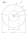
- Fig. 1 is a schematic cross section of a granular silicon particle having a seed formed in a fragmentation process
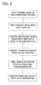
- Fig. 2 is a workflow diagram of a method of manufacturing granular silicon
- Fig. 3 is a schematic diagram of a three-reactor system suitable for production of granular silicon according to the present invention.
- Granular silicon of the present invention is in the form of a plurality of free flowing silicon particles (granules). Some of the particles comprise seeds produced in a fragmentation process and other particles comprise seeds formed by coalescence of homogeneously decomposed particles inside a reactor.
- an exemplary granular silicon particle having a seed produced in fragmentation process generally designated 1
- the silicon 5 surrounding the seed particle 3 is high purity silicon that has been deposited on the seed particle by decomposition of a silicon-bearing compound as the seed is contacted by a silicon deposition gas (e.g., silane) in a pair of fluidized bed CVD reactors.
- a silicon deposition gas e.g., silane
- the seed 3 is small piece of silicon formed by breaking a larger piece of silicon into a smaller seed sized particle (i.e., by a fragmentation process).
- the seed 3 can suitably be formed by striking a target piece of silicon with a projectile piece of silicon, substantially as set forth in U.S. Patent No. 4,691,866 .
- the seed 3 of the particle 1 shown in Fig. 1 is an externally-generated seed in that it was not produced by coalescence of homogeneously decomposed particles in a fluidized bed reactor.
- the seed 3 generally has a higher level of contamination than the surrounding silicon 5, at least initially.
- the seed has a higher concentration of transition metals (e.g., Ni, Fe, and Cr) than the surrounding silicon.
- the different contamination levels of the seed 3 and the surrounding silicon 5 is schematically indicated in Fig. 1 by the different density of speckling. Diffusion of contaminants from the seed 3 to the surrounding silicon 5 can alter the levels of contamination of the seed and the surrounding silicon over time, but this diffusion does not affect the overall contamination level of the particle 1 or of a granular silicon product comprising a plurality of such particles.
- the granular silicon particle 1 shown in Fig. 1 is illustrated as having two layers 11, 13 of silicon surrounding the seed 3. Each layer 11, 13 was deposited on the seed 3 in a different fluidized bed reactor, as set forth in the manufacturing methods discussed below. It is possible to etch a particle to expose a cross section through the particle. In actual practice, etching a particle in this manner may reveal discernable growth rings 15, indicating the boundaries between the seed 3 and inner silicon layer 11 and/or between the inner 11 and outer 13 silicon layers. However, the growth rings 15 may be obscured or absent even though the particle comprises a seed 3 and layers 11, 13 of surrounding silicon 5. Thus, the presence of growth rings is a reliable indicator that a silicon particle was formed by separate silicon deposition procedures, but the absence of growth rings is not a reliable indicator that a particle was formed by a single silicon deposition procedure.
- granular silicon of the present invention will generally be handled, transported, sold, and used in the form of a large number of silicon particles. Further, the particles normally vary somewhat in size, shape, and structure. For example, some or all of the particles may be oblong or irregularly shaped rather than approximately spherical. The particles will not all be the same size. Instead, the particles will have a size distribution. Further, in contrast to the particle 1 shown in Fig. 1, particles formed from seeds generated inside the fluidized bed reactor typically have the same low contamination levels in the seed and the surrounding silicon. The granular silicon product will be made up of particles having both kinds of seeds. The purity of the granular silicon will be, essentially, a weighted average of the purity of the constituent particles.
- the ratio of the amount of silicon in the seeds generated by a fragmentation process to the total silicon in the granular silicon is lower than in conventional granular silicon products made from seeds formed by fragmentation.
- contamination attributable to the seeds formed by fragmentation is diluted by a larger amount of higher purity silicon.
- the seeds formed by fragmentation account for no more than about 7 percent of the total mass of the granular silicon. More preferably, the seeds formed by fragmentation account for no more than about 5 percent of the total mass of the granular silicon. Still more preferably, the seeds formed by fragmentation account for no more than about 2 percent of the total mass of the granular silicon. Most preferably, the seeds formed by fragmentation account for between about 0.5 percent and about 1.5 percent of the total mass of the granular silicon.
- the granular silicon of the present invention has higher purity than conventional granular silicon. Seeds produced by fragmentation are notorious for transition metal contamination.
- the granular silicon contains less than 0.2 ppba transition metals (i.e., sum of Ni, Fe, and Cr). More preferably, the granular silicon contains between about 0.15 and about 0.1 ppba transition metals. Most preferably, the granular silicon contains no more than about 0.1 ppba transition metals.
- the iron content of the granular silicon is preferably less than about 0.13 ppba.
- the iron content is between about 0.07 ppba and about 0.13 ppba. Most preferably, the iron content is between about 0.07 ppba and about 0.1 ppba.
- the granular silicon preferably also contains no more than about 0.1 ppba boron, no more than about 0.1 ppba phosphorous, no more than about 0.03 ppba other donor contaminants (e.g., arsenic and antimony), between about 0.02 and about 0.1 ppma carbon, and between about 0.3 and about 1.5 ppmw hydrogen. It is understood that the granular silicon may have higher concentrations of one or more of the aforementioned contaminants without departing from the scope of the present invention.
- between about 0.01 and about 0.02 percent of the weight of the granular silicon is attributable to surface dust. More preferably, between about 0.006 and 0.02 percent of the weight of the granular silicon is attributable to surface dust.
- surface dust refers to material adhering to the surfaces of the particles that can be removed by liquid washing.
- the particles are desirable for the particles to be suitably sized for use in a CZ crystal puller. Size of the particles is also important because operation of a fluidized bed reactor being supplied with seeds below a certain size (e.g., 50 microns) is impractical and inefficient. However, larger seeds produced in a fragmentation process introduce more contaminants. As noted above, the particles normally vary somewhat in size and other characteristics. Therefore, particle size is specified as an average.
- the silicon particles of the granular silicon preferably have an average size between about 800 and 1200 microns. More preferably, the particles have an average size between about 900 and 1100 microns. Most preferably, the particles have an average size between about 950 and 1050 microns.
- At least 99% of the particles range in size from about 250 to about 3500 microns and less than about 0.5 percent of the total weight of the granular silicon is attributable to silicon particles that are less than about 300 microns in size.
- the seeds generated by a fragmentation process have an average size less than about 150 microns.
- the seeds generated by a fragmentation process have an average size between about 50 and 150 microns. More preferably, the seeds generated by a fragmentation process have an average size between about 75 microns and about 125 microns. Most preferably, the average size of the seeds generated by a fragmentation process is about 100 microns.
- the granular silicon of the present invention can also be produced in commercially relevant quantities using the methods described below. For instance, consistent with current industry practice for conventional granular silicon, quantities of granular silicon of the present invention weighing about 300 kg can be packaged (e.g., in a drum) for transportation. Also consistent with current industry practice for conventional granular silicon, quantities of granular silicon of the present invention weighing about one metric ton can be sold as one unit.
- the granular silicon of the present invention can be used in virtually the same manner as ordinary granular silicon. Because of the low level of contamination, however, the granular silicon contributes fewer contaminants to silicon products (e.g., semiconductor material) made with the granular silicon than would be contributed by conventional granular silicon. This facilitates production of silicon products having higher purity and fewer defects.
- the relatively uniform size distribution and low dust content of the granular silicon also makes it easier to handle, and facilitates charging and recharging of crucibles with the granular silicon.
- Granular silicon of the present invention can posses one, all, or virtually any combination of the characteristics discussed above without departing from the scope of this invention. It is sometimes particularly desirable for granular silicon to deviate from one or more of the characteristics discussed above.
- the silicon can be intentionally doped with a p or n type carrier (e.g., boron) as suggested in U.S. Patent No. 4,789,596 without departing from the scope of this invention.
- a p or n type carrier e.g., boron
- a manufacturing method of the present invention includes the following basic steps. First, as shown in Fig. 2, primary silicon seeds are produced by breaking larger silicon particles into seed sized silicon particles of a first average size. Then the primary seeds are fed to a first fluidized bed reactor where they are grown into intermediate-sized secondary seeds of a second average size by thermal decomposition of a silicon-bearing compound in the first reactor. The secondary seeds are fed into a second fluidized bed reactor where they are grown into granular silicon particles of a third average size by thermal decomposition of a silicon-bearing compound in the second reactor. Then the granular silicon is fed into a dehydrogenator that reduces the hydrogen content of the silicon particles and eliminates some of the surface dust adhering to the granular particles. Each of these steps will be discussed in more detail below.
- the primary seeds are produced by breaking larger silicon pieces into smaller particles, including the seed-sized particles of the first average size.
- the primary seeds produced in this step are essentially the same as ordinary silicon seeds except that the primary seeds are made somewhat smaller than the seeds that would ordinarily be used.
- the primary seeds that are fed into the first reactor have a first average size of less than about 150 microns.
- the primary seeds have a first average size between about 50 and about 150 microns. More preferably, the primary seeds have a first average size between about 75 and 125 microns. Most preferably, the primary seeds have a first average size of about 100 microns.
- about 90 percent of the primary seeds are between about 10 microns and about 300 microns.
- the primary seeds can be formed by crushing, grinding, milling or any other process for breaking silicon particles into smaller particles.
- One particularly desirable way to produce silicon seeds is to strike a silicon target with a stream silicon particles (e.g., 300 - 2000 micron particles) substantially as described in U.S. Patent No. 4,691,866 .
- the resulting silicon fragments are sorted by size to separate particles that are suitable for use as seeds from other particles.
- the particle classifier shown in U.S. Patent No. 4,857,173 which is hereby incorporated by reference, may be used to sort silicon fragments according to size to obtain a supply of suitably sized seeds. It is desirable to produce primary seeds having as little contamination as possible, but the seeds will usually have a transition metal concentration of about 5-10 ppba.
- Advances in seed production technology may allow seeds having lower contamination levels than can presently be obtained to be used in the future without departing from the scope of this invention.
- the methods disclosed herein can be used to produce a high-purity granular silicon product whenever silicon seeds have contamination levels exceeding the contamination levels that can be achieved for silicon deposited in a CVD reactor.
- the reactor comprises a generally cylindrical vessel 203.
- a gas inlet 205 is provided at the bottom of the reactor 201 for supplying a fluidizing gas 207 to a distributor plate 209 in the lower part of the vessel 203.
- An exhaust outlet 215 is provided at the top of the reactor 201 to allow gas to be vented from the vessel 203 to an exhaust system (not shown).
- a heater 217 is provided to heat the vessel and its contents.
- the heater can be any of a variety of heaters, such as electrical resistance heaters, electromagnetic heaters, magnetic induction heaters, or any combination thereof.
- Operation of the reactor 201 involves forming a heated particle bed 221 comprising the primary silicon seeds in the vessel 203 above the distributor plate 209.
- the particle bed 221 may be entirely made of primary seeds, but it will typically be a combination of primary seeds, previously added primary seeds that are already in the process of growing into secondary seeds, and some particles that have grown from homogeneously decomposed particles.
- the particle bed 221 is fluidized by flowing a stream of heated gas 207 up through the gas inlet 205 and distributor plate 209.
- the gas 207 used to fluidized the particle bed 221 is mixture of a carrier gas (e.g., hydrogen) and a silicon deposition gas (e.g., silane).
- the particles in the fluidized bed 221 are contacted with the silicon deposition gas.
- the silicon-bearing compound in the gas 207 decomposes because of the heat provided by the heater 217 and stored in the heated gas 207, the silicon particles 221, and the structures of the reactor 201.
- the temperature inside the reactor 201 may be between about 1100 EF and about 1300 EF. This causes silicon to be deposited on the surfaces of the particles 221.
- the first fluidized bed reactor 201 operates substantially continuously in high-throughput mode.
- the particles may be contacted with a gas comprising at least about 9 mole percent silane.
- the particles are contacted with a gas comprising more than about 14 mole percent silane. More preferably, the particles are contacted with a gas comprising between about 16 and 24 mole percent silane. Most preferably, the particles are contacted with a gas comprising between about 18 and 20 mole percent silane.
- a mixture of silane and carrier gas having the specified concentration of silane is introduced to the reactor at the inlet 205 as shown in Fig. 3.
- the reactor 201 is operated with an internal pressure between about 5 and about 15 psig.
- the internal pressure can range from subatmospheric to several atmospheres without departing from the scope of this invention.
- the secondary seed particles are periodically or substantially continuously harvested from the first reactor 201 in any manner known to those skilled in the art. For example, a portion (e.g., 15 percent) of the particles can be harvested periodically (e.g., about every four hours). Additional primary seeds are periodically or substantially continuously fed to the reactor to keep the total number of particles in the reactor within a desired range. Because the particle bed is thoroughly mixed by the fluidization process, some of the secondary seeds harvested from the first reactor will have spent more time in the first reactor and grown larger than others.
- the secondary seeds harvested from the first reactor have a second average size larger than the first average size of the primary seeds.
- the secondary seeds harvested from the first reactor have an average size of at least about 250 microns. More preferably, the average size of the secondary seeds is between about 250 microns to about 600 microns. Most preferably, the secondary seeds have an average size between about 400 and about 500 microns.
- the amount of particle growth for a fluidized bed reactor is commonly expressed as a growth ratio, which is the ratio of the mass of the seeds added to the reactor to the mass of the harvested silicon particles.
- the growth ratio of the first reactor 201 is between about 13 and about 20. That range of growth factor indicates between about 1 /13 and about 1 / 20 of the mass of the secondary seeds is attributable to the primary seeds. The rest of the mass is attributable to decomposition of the silicon deposition gas and has a higher purity than the primary seeds.
- the growth ratio of the first reactor 201 is augmented by production of additional seeds formed by coalescence of homogeneously decomposed particles in the first reactor, as discussed in more detail below.
- the secondary seeds are fed into the second fluidized bed (chemical vapor deposition) reactor 301, where they are grown into larger granular silicon particles.
- the configuration of the second reactor 301 is not critical to the invention.
- the basic design and operation of the second reactor 301 is substantially similar to the first reactor except as noted herein.
- the second reactor 301 is operated substantially continuously in high-throughput mode.
- the particles 321 in the second reactor 301 are contacted with a gas 307 comprising at least 7 mole percent silane.
- the particles 321 in the second reactor 301 are contacted with a gas 307 having a silane concentration greater than about 7 mole percent and less than the silane concentration of the gas 207 used to contact the particles 221 in the first reactor 201.
- the particles 321 in the second reactor 301 are contacted with a gas 307 having a silane concentration between about 7 and about 13 mole percent.
- the secondary seeds grow into larger granular silicon particles, which are periodically or substantially continuously harvested from the second reactor 301 in a manner similar to the way particles are harvested from the first reactor 201.
- the granular silicon particles harvested from the second reactor 301 have a third average size between about 800 and about 1200 microns. More preferably, the granular silicon particles harvested from the second reactor 301 have an average size between about 900 and about 1100 microns. Most preferably, the granular silicon particles harvested from the second reactor 301 have an average size between about 950 and about 1050 microns.
- the growth ratio of the second reactor 301 is between about 5 and about 10.
- the combined growth ratio of the first 201 and second 301 reactors together i.e., the ratio of the mass of the primary seeds fed to the first reactor 201 to the mass of the granular silicon particles harvested from the second reactor 301 is between about 65 and about 200. More preferably, the combined growth ratio of the first 201 and second 301 reactors is between about 90 and 150.
- One aspect of the invention is that the operation of the first 201 and second 301 fluidized bed reactors is influenced by the difference in the average particle size of the particles in the first 221 and second 321 fluidized beds.
- average particle size influences a number of other characteristics of a fluidized bed. For example, for any given ratio of fluidizing gas velocity (U) to the minimum gas velocity capable of fluidizing the bed (U mf ), bubble bypassing is greater when the average particle size is smaller. An increase in bubble bypassing favors homogeneous decomposition.
- the average particle size of the particles in the first reactor 201 is smaller than the average particle size in an ordinary silicon producing CVD fluidized bed reactor. It is also smaller than the average particle size of particles in the second reactor 301. Conversely, the average size of the particles in the second reactor 301 is larger than would be found in a typical silicon producing CVD fluidized bed reactor.
- the average particle size in the first reactor 201 is between about 300 and 600 microns and the average particle size in the second reactor is between about 800 and 1200 microns.
- the smaller average particle size of particles in the first reactor 201 is more favorable for homogeneous decomposition and results in a lower U mf for the first reactor.
- U mf for the second reactor 301 is higher than it is for ordinary silicon producing fluidized bed reactors because of the larger average particle size in the second reactor.
- the ratio of U/U mf for the first reactor 201 is between 1 and about 5 and the ratio of U/U mf for the second reactor 301 is between 1 and about 3. More preferably, the ratio of U/U mf for the first reactor 201 is between about 2 and about 4 and the ratio of U/U mf for the second reactor 301 is between 1 and about 2.
- the first reactor 201 can be operated with a lower gas velocity than the velocities ordinarily used for production of silicon in a fluidized bed reactor. This allows a comparatively larger fraction of the homogeneously decomposed fines to remain in the fluidized bed 221 of the first reactor 201 rather than being blown out through the exhaust outlet 215 into the exhaust system. Accordingly, the first reactor 201 experiences an increase in the amount of self-seeding because some of the homogeneously decomposed fines that would normally be lost in the exhaust coalesce inside the reactor to form internally-generated seeds that then grow into secondary seeds.
- the increase in the fraction of homogeneously decomposed particles that coalesce to form seeds in the first reactor 201 also reduces the seed requirement for the process, thereby improving efficiency.
- the benefits of the self-seeding make it economical to increase the concentration of silane above 14 mole percent to increase the throughput of the first reactor 201 and generate homogeneously decomposed particles for partially self-seeding the first reactor.
- the silane concentration is lower in the second reactor 301 than the first reactor 201, which also favors heterogeneous decomposition.
- the particles in the second reactor 301 are fluidized by flowing gas 307 upwardly through the reactor at a rate higher than is used in the first reactor 201.
- Small dust sized particles in the second reactor 301 are more likely to be blown out of the fluidized bed through the exhaust outlet 315 because of the relatively higher gas velocity. This does reduce the amount of self-seeding in the second reactor 301, but this is more than offset by the increase in the ratio of heterogeneous to homogeneous decomposition caused by the larger average particle size in the second reactor 301.
- the higher gas velocity in the second reactor 301 translates to more silicon deposition gas being passed through the particle bed 321 in a given amount of time for a given concentration, thereby increasing the throughput of the second reactor 301.
- the granular silicon harvested from the second reactor 301 can be used as is without departing from the scope of the invention. If the granular silicon is to be used for recharge of a crucible in a CZ crystal puller, however, it will be desirable to reduce the hydrogen content of the granular silicon. It may also be desirable to further reduce the dust content of the granular silicon harvested from the second reactor 301. Both hydrogen and dust reduction can be achieved by feeding the granular silicon particles from the second reactor 301 into a fluidized bed dehydrogenator 401. For example, the granular silicon particles harvested from the second reactor 301 can be fed into the fluidized bed dehydrogenator described in U.S. Patent No. 5,326,547 , which is hereby incorporated by reference.
- the dehydrogenator 401 operates by fluidizing a bed of silicon particles 421 with an inert gas 407 (e.g., hydrogen) at temperatures higher than the temperatures encountered in CVD fluidized bed reactors for decomposition of silicon-bearing compounds. Hydrogen diffuses out of the particles over time at this higher temperature.
- an inert gas 407 e.g., hydrogen
- granular silicon harvested from the second reactor 301 is fed into a fluidized bed dehydrogenator 401 and held between about 1800 and about 2200 EF for a period of time sufficient to reduce the hydrogen content of the granular silicon to about 0.3 to about 1.5 ppmw. This step also reduces the dust content of the granular silicon.
- granular silicon particles harvested from the second reactor 301 can have a surface dust content of about 0.1 to about 0.4 weight percent.
- the dehydrogenation process can reduce the surface dust content to between about 0.01 and about 0.02 weight percent. More preferably, the dehydrogenation process can reduce the surface dust content to between about 0.01 and about 0.006 weight percent.
- the dehydrogenation process reduces the dust content by at least about 80 percent. More preferably, the dust content is reduced by at least about 95 percent. Most preferably, the dust content is reduced by at least about 98 percent.
- the methods of the present invention provide advantages from the standpoint of product purity. They also provide a number of advantages from an efficiency standpoint.
- the yield can be increased about 2-5 percent over the best conventional practices.
- the throughput can be increased about 15-20 percent over the best conventional practices.
- Throughput can be measured in terms of the ratio of the rate of silicon production to the size of the reactor vessel (expressed in terms of the average cross sectional area of the reactor).
- the throughput through the second reactor is at least about 140 kg/h per m 2 . In the embodiment described herein, the throughput of the second reactor is between about 140 kg/h per m 2 and about 155 kg/h per m 2 .
- Silicon deposition gas e.g., silane
- the carrier e.g., hydrogen
- the silicon deposition gas can be introduced to the reactor at a different location from the fluidizing gas or even through a plurality of inlets at various location in the reactor, to name just a few of the countless variations that are possible.
Landscapes
- Chemical & Material Sciences (AREA)
- Organic Chemistry (AREA)
- Inorganic Chemistry (AREA)
- Mechanical Engineering (AREA)
- Engineering & Computer Science (AREA)
- Materials Engineering (AREA)
- Chemical Kinetics & Catalysis (AREA)
- Metallurgy (AREA)
- General Chemical & Material Sciences (AREA)
- Silicon Compounds (AREA)
- Crystals, And After-Treatments Of Crystals (AREA)
- Catalysts (AREA)
- Chemical Vapour Deposition (AREA)
Applications Claiming Priority (2)
| Application Number | Priority Date | Filing Date | Title |
|---|---|---|---|
| US10/988,179 US20060105105A1 (en) | 2004-11-12 | 2004-11-12 | High purity granular silicon and method of manufacturing the same |
| EP05851459A EP1833759B1 (en) | 2004-11-12 | 2005-11-10 | High purity granular silicon and method of manufacturing the same |
Related Parent Applications (1)
| Application Number | Title | Priority Date | Filing Date |
|---|---|---|---|
| EP05851459A Division EP1833759B1 (en) | 2004-11-12 | 2005-11-10 | High purity granular silicon and method of manufacturing the same |
Publications (1)
| Publication Number | Publication Date |
|---|---|
| EP1900685A1 true EP1900685A1 (en) | 2008-03-19 |
Family
ID=35976382
Family Applications (4)
| Application Number | Title | Priority Date | Filing Date |
|---|---|---|---|
| EP07120116A Not-in-force EP1900686B1 (en) | 2004-11-12 | 2005-11-10 | Method of making dust-free granular silicon |
| EP07120114A Not-in-force EP1900684B1 (en) | 2004-11-12 | 2005-11-10 | High-purity granular silicon composition |
| EP07120115A Withdrawn EP1900685A1 (en) | 2004-11-12 | 2005-11-10 | Dust-free granular silicon composition |
| EP05851459A Not-in-force EP1833759B1 (en) | 2004-11-12 | 2005-11-10 | High purity granular silicon and method of manufacturing the same |
Family Applications Before (2)
| Application Number | Title | Priority Date | Filing Date |
|---|---|---|---|
| EP07120116A Not-in-force EP1900686B1 (en) | 2004-11-12 | 2005-11-10 | Method of making dust-free granular silicon |
| EP07120114A Not-in-force EP1900684B1 (en) | 2004-11-12 | 2005-11-10 | High-purity granular silicon composition |
Family Applications After (1)
| Application Number | Title | Priority Date | Filing Date |
|---|---|---|---|
| EP05851459A Not-in-force EP1833759B1 (en) | 2004-11-12 | 2005-11-10 | High purity granular silicon and method of manufacturing the same |
Country Status (8)
| Country | Link |
|---|---|
| US (2) | US20060105105A1 (ko) |
| EP (4) | EP1900686B1 (ko) |
| JP (2) | JP5238258B2 (ko) |
| KR (3) | KR101370104B1 (ko) |
| CN (2) | CN101076493B (ko) |
| DE (2) | DE602005018839D1 (ko) |
| TW (2) | TWI338723B (ko) |
| WO (1) | WO2006062660A2 (ko) |
Families Citing this family (26)
| Publication number | Priority date | Publication date | Assignee | Title |
|---|---|---|---|---|
| US7789331B2 (en) * | 2006-09-06 | 2010-09-07 | Integrated Photovoltaics, Inc. | Jet mill producing fine silicon powder |
| WO2009158650A1 (en) * | 2008-06-27 | 2009-12-30 | Memc Electronic Materials, Inc. | Methods for increasing polycrystalline silicon reactor productivity by recycle of silicon fines |
| DE102008036143A1 (de) | 2008-08-01 | 2010-02-04 | Berlinsolar Gmbh | Verfahren zum Entfernen von nichtmetallischen Verunreinigungen aus metallurgischem Silicium |
| CN101676203B (zh) * | 2008-09-16 | 2015-06-10 | 储晞 | 生产高纯颗粒硅的方法 |
| US8168123B2 (en) * | 2009-02-26 | 2012-05-01 | Siliken Chemicals, S.L. | Fluidized bed reactor for production of high purity silicon |
| TWI454309B (zh) * | 2009-04-20 | 2014-10-01 | Jiangsu Zhongneng Polysilicon Technology Dev Co Ltd | 用於將反應排出氣體冷卻之方法及系統 |
| US8425855B2 (en) | 2009-04-20 | 2013-04-23 | Robert Froehlich | Reactor with silicide-coated metal surfaces |
| DE102010040293A1 (de) | 2010-09-06 | 2012-03-08 | Wacker Chemie Ag | Verfahren zur Herstellung von polykristallinem Silicium |
| US20120148728A1 (en) * | 2010-12-09 | 2012-06-14 | Siliken Sa | Methods and apparatus for the production of high purity silicon |
| TWI580825B (zh) | 2012-01-27 | 2017-05-01 | Memc新加坡有限公司 | 藉由定向固化作用製備鑄態矽之方法 |
| RU2492914C2 (ru) * | 2012-04-03 | 2013-09-20 | Федеральное государственное бюджетное учреждение науки Институт высокотемпературной электрохимии Уральского отделения Российской Академии наук | Молекулярный фильтр для извлечения гелия из гелийсодержащих газовых смесей |
| DE102012206439A1 (de) * | 2012-04-19 | 2013-10-24 | Wacker Chemie Ag | Polykristallines Siliciumgranulat und seine Herstellung |
| US8875728B2 (en) | 2012-07-12 | 2014-11-04 | Siliken Chemicals, S.L. | Cooled gas distribution plate, thermal bridge breaking system, and related methods |
| US10105669B2 (en) | 2012-08-29 | 2018-10-23 | Hemlock Semiconductor Operations Llc | Tapered fluidized bed reactor and process for its use |
| WO2014064892A1 (ja) | 2012-10-26 | 2014-05-01 | パナソニック株式会社 | 端末装置、基地局装置、受信方法及び送信方法 |
| US8833564B1 (en) * | 2013-03-13 | 2014-09-16 | Sunedison Semiconductor Limited | Systems and methods for reducing dust in granular material |
| CN103213989B (zh) * | 2013-03-19 | 2014-12-31 | 浙江精功新材料技术有限公司 | 一种多晶硅颗粒制备系统及制备方法 |
| US10525430B2 (en) | 2013-12-26 | 2020-01-07 | Bruce Hazeltine | Draft tube fluidized bed reactor for deposition of granular silicon |
| DE102014221928A1 (de) | 2014-10-28 | 2016-04-28 | Wacker Chemie Ag | Wirbelschichtreaktor und Verfahren zur Herstellung von polykristallinem Siliciumgranulat |
| US9440262B2 (en) | 2014-11-07 | 2016-09-13 | Rec Silicon Inc | Apparatus and method for silicon powder management |
| CA2972186A1 (en) * | 2014-12-23 | 2016-06-30 | Sitec Gmbh | Mechanically fluidized deposition systems and methods |
| US9682404B1 (en) | 2016-05-05 | 2017-06-20 | Rec Silicon Inc | Method and apparatus for separating fine particulate material from a mixture of coarse particulate material and fine particulate material |
| US10287171B2 (en) | 2016-05-05 | 2019-05-14 | Rec Silicon Inc | Tumbling device for the separation of granular polysilicon and polysilicon powder |
| US10407310B2 (en) | 2017-01-26 | 2019-09-10 | Rec Silicon Inc | System for reducing agglomeration during annealing of flowable, finely divided solids |
| EP3700860A4 (en) | 2017-10-27 | 2021-08-11 | Northern Silicon Inc. | SYSTEM AND PROCESS FOR MANUFACTURING HIGHLY PURE SILICON |
| CN109529732B (zh) * | 2018-12-24 | 2020-01-10 | 亚洲硅业(青海)有限公司 | 一种流化处理系统 |
Citations (12)
| Publication number | Priority date | Publication date | Assignee | Title |
|---|---|---|---|---|
| US4691866A (en) | 1985-11-08 | 1987-09-08 | Ethyl Corporation | Generation of seed particles |
| US4789596A (en) | 1987-11-27 | 1988-12-06 | Ethyl Corporation | Dopant coated bead-like silicon particles |
| US4820587A (en) | 1986-08-25 | 1989-04-11 | Ethyl Corporation | Polysilicon produced by a fluid bed process |
| US4851297A (en) | 1987-11-27 | 1989-07-25 | Ethyl Corporation | Dopant coated bead-like silicon particles |
| US4857173A (en) | 1986-01-31 | 1989-08-15 | Ethyl Corporation | Particle classifier and method |
| US4868013A (en) | 1987-08-21 | 1989-09-19 | Ethyl Corporation | Fluidized bed process |
| JPH0578115A (ja) * | 1991-07-29 | 1993-03-30 | Mitsubishi Materials Corp | 粒状シリコン多結晶の製造方法 |
| US5322670A (en) | 1992-10-20 | 1994-06-21 | Ethyl Corporation | Product recovery tube assembly |
| US5405658A (en) | 1992-10-20 | 1995-04-11 | Albemarle Corporation | Silicon coating process |
| US5919303A (en) | 1997-10-16 | 1999-07-06 | Memc Electronic Materials, Inc. | Process for preparing a silicon melt from a polysilicon charge |
| US5976481A (en) * | 1996-05-21 | 1999-11-02 | Tokuyama Corporation | Polycrystal silicon rod and production process therefor |
| EP1544167A1 (de) * | 2003-12-18 | 2005-06-22 | Wacker-Chemie GmbH | Staub- und porenfreies hochreines Polysiliciumgranulat |
Family Cites Families (19)
| Publication number | Priority date | Publication date | Assignee | Title |
|---|---|---|---|---|
| US3012861A (en) * | 1960-01-15 | 1961-12-12 | Du Pont | Production of silicon |
| US4314525A (en) * | 1980-03-03 | 1982-02-09 | California Institute Of Technology | Fluidized bed silicon deposition from silane |
| US4444811A (en) * | 1980-03-03 | 1984-04-24 | California Institute Of Technology | Fluidized bed silicon deposition from silane |
| US4424199A (en) * | 1981-12-11 | 1984-01-03 | Union Carbide Corporation | Fluid jet seed particle generator for silane pyrolysis reactor |
| US4883687A (en) * | 1986-08-25 | 1989-11-28 | Ethyl Corporation | Fluid bed process for producing polysilicon |
| US4784840A (en) * | 1986-08-25 | 1988-11-15 | Ethyl Corporation | Polysilicon fluid bed process and product |
| JPH0755810B2 (ja) * | 1987-03-14 | 1995-06-14 | 三井東圧化学株式会社 | 高純度粒状珪素とその製造方法 |
| US4871524A (en) * | 1987-09-03 | 1989-10-03 | Ethyl Corporation | Hydrogen purification process |
| US5037503A (en) * | 1988-05-31 | 1991-08-06 | Osaka Titanium Co., Ltd. | Method for growing silicon single crystal |
| US5326547A (en) * | 1988-10-11 | 1994-07-05 | Albemarle Corporation | Process for preparing polysilicon with diminished hydrogen content by using a two-step heating process |
| US5242671A (en) * | 1988-10-11 | 1993-09-07 | Ethyl Corporation | Process for preparing polysilicon with diminished hydrogen content by using a fluidized bed with a two-step heating process |
| CA1340189C (en) * | 1988-10-11 | 1998-12-15 | Albemarle Corporation | Polysilicon with diminished hydrogen content |
| NO165288C (no) * | 1988-12-08 | 1991-01-23 | Elkem As | Silisiumpulver og fremgangsmaate for fremstilling av silisiumpulver. |
| US5236547A (en) * | 1990-09-25 | 1993-08-17 | Kabushiki Kaisha Toshiba | Method of forming a pattern in semiconductor device manufacturing process |
| JPH06127923A (ja) * | 1992-10-16 | 1994-05-10 | Tonen Chem Corp | 多結晶シリコン製造用流動層反応器 |
| US5810934A (en) * | 1995-06-07 | 1998-09-22 | Advanced Silicon Materials, Inc. | Silicon deposition reactor apparatus |
| BR9611816A (pt) * | 1996-10-14 | 1999-07-13 | Kawasaki Steel Co | Processo e aparelho para fabricação de silício policristalino e processo para fabricação de pastilhas de silício para baterias solares |
| US6827786B2 (en) * | 2000-12-26 | 2004-12-07 | Stephen M Lord | Machine for production of granular silicon |
| CN1171784C (zh) * | 2002-03-05 | 2004-10-20 | 浙江大学 | 纳米硅管的制备方法 |
-
2004
- 2004-11-12 US US10/988,179 patent/US20060105105A1/en not_active Abandoned
-
2005
- 2005-11-10 EP EP07120116A patent/EP1900686B1/en not_active Not-in-force
- 2005-11-10 EP EP07120114A patent/EP1900684B1/en not_active Not-in-force
- 2005-11-10 DE DE602005018839T patent/DE602005018839D1/de active Active
- 2005-11-10 KR KR1020127007690A patent/KR101370104B1/ko active IP Right Grant
- 2005-11-10 DE DE602005025930T patent/DE602005025930D1/de active Active
- 2005-11-10 WO PCT/US2005/040559 patent/WO2006062660A2/en active Application Filing
- 2005-11-10 EP EP07120115A patent/EP1900685A1/en not_active Withdrawn
- 2005-11-10 KR KR1020117000929A patent/KR101321675B1/ko active IP Right Grant
- 2005-11-10 EP EP05851459A patent/EP1833759B1/en not_active Not-in-force
- 2005-11-10 JP JP2007541287A patent/JP5238258B2/ja active Active
- 2005-11-10 KR KR1020077010827A patent/KR20070085338A/ko not_active Application Discontinuation
- 2005-11-10 CN CN2005800388410A patent/CN101076493B/zh active Active
- 2005-11-10 CN CN2009102615052A patent/CN101734664B/zh active Active
- 2005-11-11 TW TW094139670A patent/TWI338723B/zh active
- 2005-11-11 TW TW099141603A patent/TW201122144A/zh unknown
-
2008
- 2008-04-09 US US12/100,151 patent/US20080187481A1/en not_active Abandoned
-
2012
- 2012-08-28 JP JP2012187792A patent/JP5623478B2/ja active Active
Patent Citations (12)
| Publication number | Priority date | Publication date | Assignee | Title |
|---|---|---|---|---|
| US4691866A (en) | 1985-11-08 | 1987-09-08 | Ethyl Corporation | Generation of seed particles |
| US4857173A (en) | 1986-01-31 | 1989-08-15 | Ethyl Corporation | Particle classifier and method |
| US4820587A (en) | 1986-08-25 | 1989-04-11 | Ethyl Corporation | Polysilicon produced by a fluid bed process |
| US4868013A (en) | 1987-08-21 | 1989-09-19 | Ethyl Corporation | Fluidized bed process |
| US4789596A (en) | 1987-11-27 | 1988-12-06 | Ethyl Corporation | Dopant coated bead-like silicon particles |
| US4851297A (en) | 1987-11-27 | 1989-07-25 | Ethyl Corporation | Dopant coated bead-like silicon particles |
| JPH0578115A (ja) * | 1991-07-29 | 1993-03-30 | Mitsubishi Materials Corp | 粒状シリコン多結晶の製造方法 |
| US5322670A (en) | 1992-10-20 | 1994-06-21 | Ethyl Corporation | Product recovery tube assembly |
| US5405658A (en) | 1992-10-20 | 1995-04-11 | Albemarle Corporation | Silicon coating process |
| US5976481A (en) * | 1996-05-21 | 1999-11-02 | Tokuyama Corporation | Polycrystal silicon rod and production process therefor |
| US5919303A (en) | 1997-10-16 | 1999-07-06 | Memc Electronic Materials, Inc. | Process for preparing a silicon melt from a polysilicon charge |
| EP1544167A1 (de) * | 2003-12-18 | 2005-06-22 | Wacker-Chemie GmbH | Staub- und porenfreies hochreines Polysiliciumgranulat |
Also Published As
| Publication number | Publication date |
|---|---|
| EP1900684A1 (en) | 2008-03-19 |
| KR101321675B1 (ko) | 2013-10-22 |
| DE602005018839D1 (de) | 2010-02-25 |
| JP5623478B2 (ja) | 2014-11-12 |
| CN101076493A (zh) | 2007-11-21 |
| JP2008519754A (ja) | 2008-06-12 |
| KR101370104B1 (ko) | 2014-03-04 |
| EP1900686B1 (en) | 2012-02-08 |
| US20060105105A1 (en) | 2006-05-18 |
| CN101734664A (zh) | 2010-06-16 |
| JP2012236768A (ja) | 2012-12-06 |
| TW200622026A (en) | 2006-07-01 |
| EP1833759B1 (en) | 2011-01-12 |
| KR20110019425A (ko) | 2011-02-25 |
| KR20120041268A (ko) | 2012-04-30 |
| KR20070085338A (ko) | 2007-08-27 |
| EP1900686A1 (en) | 2008-03-19 |
| JP5238258B2 (ja) | 2013-07-17 |
| TW201122144A (en) | 2011-07-01 |
| CN101734664B (zh) | 2012-10-31 |
| US20080187481A1 (en) | 2008-08-07 |
| CN101076493B (zh) | 2010-05-05 |
| WO2006062660A2 (en) | 2006-06-15 |
| EP1833759A2 (en) | 2007-09-19 |
| WO2006062660A3 (en) | 2007-08-02 |
| DE602005025930D1 (de) | 2011-02-24 |
| EP1900684B1 (en) | 2010-01-06 |
| TWI338723B (en) | 2011-03-11 |
Similar Documents
| Publication | Publication Date | Title |
|---|---|---|
| EP1900684B1 (en) | High-purity granular silicon composition | |
| JP4567430B2 (ja) | ダスト不含および孔不含の高純度多結晶シリコン顆粒およびその製法およびその使用 | |
| KR101532478B1 (ko) | 과립형 다결정 실리콘 및 이의 제법 | |
| US8658118B2 (en) | High purity crystalline silicon, high purity silicon tetrachloride for processes for producing the same | |
| US4851297A (en) | Dopant coated bead-like silicon particles | |
| CN101243014B (zh) | 硅的制备方法 | |
| US4789596A (en) | Dopant coated bead-like silicon particles | |
| JP7391872B2 (ja) | トリクロロシランを調製するためのシリコン顆粒、及び関連する製造方法 | |
| JPH02164711A (ja) | 高純度ボロンの製造方法 | |
| JPH06127923A (ja) | 多結晶シリコン製造用流動層反応器 | |
| EP0450393A2 (en) | Improved polysilicon and process therefor | |
| EP0494699A2 (en) | High purity doping alloys |
Legal Events
| Date | Code | Title | Description |
|---|---|---|---|
| PUAI | Public reference made under article 153(3) epc to a published international application that has entered the european phase |
Free format text: ORIGINAL CODE: 0009012 |
|
| AC | Divisional application: reference to earlier application |
Ref document number: 1833759 Country of ref document: EP Kind code of ref document: P |
|
| AK | Designated contracting states |
Kind code of ref document: A1 Designated state(s): DE FR GB IT |
|
| AX | Request for extension of the european patent |
Extension state: AL BA HR MK YU |
|
| 17P | Request for examination filed |
Effective date: 20080610 |
|
| 17Q | First examination report despatched |
Effective date: 20080717 |
|
| AKX | Designation fees paid |
Designated state(s): DE FR GB IT |
|
| STAA | Information on the status of an ep patent application or granted ep patent |
Free format text: STATUS: THE APPLICATION IS DEEMED TO BE WITHDRAWN |
|
| 18D | Application deemed to be withdrawn |
Effective date: 20091112 |