EP1900611A2 - Axe de dolly - Google Patents
Axe de dolly Download PDFInfo
- Publication number
- EP1900611A2 EP1900611A2 EP07013638A EP07013638A EP1900611A2 EP 1900611 A2 EP1900611 A2 EP 1900611A2 EP 07013638 A EP07013638 A EP 07013638A EP 07013638 A EP07013638 A EP 07013638A EP 1900611 A2 EP1900611 A2 EP 1900611A2
- Authority
- EP
- European Patent Office
- Prior art keywords
- drawbar
- dolly axle
- axle according
- dolly
- damper
- Prior art date
- Legal status (The legal status is an assumption and is not a legal conclusion. Google has not performed a legal analysis and makes no representation as to the accuracy of the status listed.)
- Withdrawn
Links
Images


Classifications
-
- B—PERFORMING OPERATIONS; TRANSPORTING
- B62—LAND VEHICLES FOR TRAVELLING OTHERWISE THAN ON RAILS
- B62D—MOTOR VEHICLES; TRAILERS
- B62D53/00—Tractor-trailer combinations; Road trains
- B62D53/04—Tractor-trailer combinations; Road trains comprising a vehicle carrying an essential part of the other vehicle's load by having supporting means for the front or rear part of the other vehicle
- B62D53/08—Fifth wheel traction couplings
- B62D53/0857—Auxiliary semi-trailer handling or loading equipment, e.g. ramps, rigs, coupling supports
- B62D53/0864—Dollies for fifth wheel coupling
-
- B—PERFORMING OPERATIONS; TRANSPORTING
- B62—LAND VEHICLES FOR TRAVELLING OTHERWISE THAN ON RAILS
- B62D—MOTOR VEHICLES; TRAILERS
- B62D13/00—Steering specially adapted for trailers
- B62D13/04—Steering specially adapted for trailers for individually-pivoted wheels
-
- B—PERFORMING OPERATIONS; TRANSPORTING
- B62—LAND VEHICLES FOR TRAVELLING OTHERWISE THAN ON RAILS
- B62D—MOTOR VEHICLES; TRAILERS
- B62D13/00—Steering specially adapted for trailers
- B62D13/06—Steering specially adapted for trailers for backing a normally drawn trailer
Definitions
- the invention relates to a dolly axle with a drawbar rotatably mounted on a frame about a vertical axis and a saddle dome arranged on the upper side of the frame and at least one wheelset which is steerable by the pivoting movement of the drawbar transmitted transmission means, preferably at least one as transmission means Steering arm is provided, with which the pivoting movement of the drawbar is transferable to at least one steering lever acting on the steerable wheelset and in particular the position of the shift control arm is variable by driven adjusting means.
- Such a dolly axis is from the EP 1 466 813 B known.
- a link arm having intermediate levers are provided as transmission means with which the pivoting movement of the drawbar on steering levers, which act on the steerable wheelset, can be transmitted.
- the position of the intermediate lever is variable by driven adjusting means, so that the inevitably resulting in steering movements pivotal movement of the drawbar can be used to initiate a steering angle of a steerable wheelset via the steering handlebar.
- the drawbar is connected to the frame, that the vertical pivot axis intersects the wheel axle of the steerable wheelset centered.
- motor drives and gearbox simple mechanical components can be used in this known dolly axle, wherein by the pivoting movement of the drawbar a steering angle is predetermined, which is transmitted by the control links according to the steerable wheelset.
- a steering angle is predetermined, which is transmitted by the control links according to the steerable wheelset.
- the geometry of the transmission means is changed.
- steering movements arise in different positions of the shift handlebars different strong steering movements at the same steering angle of the drawbar.
- a switching position of the control arm so less steering movements can be transmitted to a steerable wheelset, for example, at low shunting speeds of the drawbar, while in another switching position of the control arm at, for example, higher speeds transmitted by the drawbar parking paths at the same angle of the drawbar are greater.
- the dolly axle of the type mentioned is characterized by the fact that the pivot axis of the drawbar is located in the forward direction of the wheel axle of the wheelset, which absorbs the prevailing tensile load, which is accompanied even after extended periods of use a more balanced and quiet running.
- the adjusting lever is variable in position on the drawbar pivotally fixed and that the adjusting lever and the steering correction lever are variable in position to each other can be fixed.
- a steering geometry is implemented in the dolly axle, in which a steering angle correction can be carried out, preferably in cooperation with a steering damper and a rotatable saddle dome, which will be presented in more detail below.
- the steering angle of the inner and outer wheels is adapted to the actual existing angles of the curves or circular drive. This is accompanied by a lower tire wear and a rolling resistance minimization.
- the adjusting lever is provided, on which a steering lever hingedly engages, which in turn is pivotally connected to the handlebar. Due to the distance ratios of the articulation points provided in this case, the corresponding steering angle correction can be performed.
- the spacing conditions are adjustable and thus changeable.
- the shift control arm swivel axes which are located in the forward direction of travel in front of the pivot axis of the drawbar.
- the drawbar is supported on at least one damper on the frame.
- a dolly axle is provided in which rolling movements and also a rocking of the vehicle combination are to be significantly reduced overall.
- the damper is always in use, so that there is always a damped state of the drawbar even with different angles of the drawbar.
- two dampers are provided, each in the direction of travel right and left - based on the center position of the drawbar - attack on this one end and the other end are supported on the frame.
- Preferred dimensions of the respective damper is a component having a threaded rod, a driver cup, a housing and an inner spring, wherein the threaded rod relative to the driver cup and the housing and the driver cup are movable relative to the housing.
- This can take various positions for the drawbar, namely once a middle position in which no force is built, and respective end positions with inserted driver cup and retracted threaded rod and a respective extended position of the threaded rod in the inside displacement of the driver cup together with the spring and of course corresponding intermediate positions ,
- the neutral position ie the center position of the drawbar, the bearing of the threaded rod is unloaded, wherein it comes in the respective end positions to a load on the threaded rod in the corresponding bearing points, which counteracts any rolling movements.
- the fifth wheel plate is preferably limited in terms of its rotational movement or with respect to its rotation.
- the saddle plate or the saddle dome is rotatably mounted, so incurred by a friction between saddle dome and semi-trailer low frictional forces. Larger occurring friction forces would cause a rocking of the vehicle combination.
- an intended tie rod or handlebar the coupling process without manual intervention is possible.
- the use of standard axes is possible. In combination with the steering damper and the rotatable saddle dome swinging is effectively prevented.
- the dampers which attack both sides of the drawbar, a provision of the drawbar in the neutral position is possible.
- an end stop is also provided on the frame in order to limit the maximum deflection of the drawbar.
- a reverse lock is also provided, in which via a connectable to the drawbar spring-loaded vomfahrsperrklaue the drawbar is locked, in its neutral position.
- This reverse lock can be operated via a cylinder.
- the drawbar is adjustable in height connected to the frame, including a mounting arrangement is provided with superposed mounting holes.
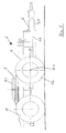
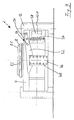
- Fig. 1 is a side view of a dolly axis 2 can be seen.
- the dolly axle 2 has a frame 4, a drawbar 6, a fifth wheel 8, a steerable wheel set 10 and a non-steerable wheel set 12 with a wheel axle 12.1.
- the drawbar 6 is formed in two parts and has a front drawbar part 6.1 and a rear, connected to the frame 4 drawbar part 6.2.
- the drawbar 6 can be attached with its front end to a trailer hitch of a towing vehicle.
- the shape of the drawbar is not limited to the embodiment shown in the embodiment, but may also have other shapes, such as a gooseneck drawbar.
- a semi-trailer can be firmly connected to the fifth wheel 8.
- the corresponding truck can have additional cargo space, which is arranged for example on the towing vehicle.
- the drawbar is about a pivot axis 14, which is located in order to achieve a smooth running even after prolonged periods of use in front of the wheel axle 12.1, pivotally, as is apparent from Fig. 2 in more detail.
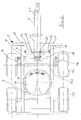
- the dolly axle 2 can be seen from a top view, in a position in which the drawbar 6 is with its front part 6.1 and its rear part 6.2 in its neutral position for a straight ahead. Due to the two-part drawbar the simple possibility is created to equip the vehicle for both low and normal dome heights.
- the fifth wheel 8 is arranged approximately centrally between the steerable wheelset 10 and the non-steerable wheelset 12.
- the dolly axis 2 is thus shown as Zweiachsaus exit, but can also be equipped and used as a one-axis or more than two axes accordingly.
- the steering levers 16 can be seen on which attack in detail not shown transmission means. These are spaced from the axis of rotation of the steering joint arranged to use a lever travel for the adjustment of the steering angle can.
- the transmission means consist in the embodiment of a shift link 18 and a tie rod 18.
- a shift link 18 is provided which engages articulated at 20 to the drawbar 6.
- the pivot axes 20 are located in the forward direction in front of the pivot axis 14 of the drawbar, which in turn, due to the always existing tensile load advantageously has an effect on the smooth running of the dolly axle and in the case of worn bearings.
- each end stop 24 is provided on the frame 4.
- These steering bar stops 24 prevent excessive steering of a vehicle combination.
- These can also be equipped so that when a stop of the drawbar 6 on the stop 24, an optical or acoustic signal is generated for a corresponding driver information.
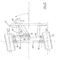
- Fig. 3 is a maximum traction drawbar 6 is otherwise illustrated with an analogous structure as in the embodiment of FIG. 2.
- the drawbar 6 is located at the top stop 24 in the drawing. In the embodiment shown, this corresponds to a drawbar maximum angle of 33 °.
- the drawbar movement has been transferred to the steerable wheelset 12.
- the drawbar has been moved against the attacking damper 22, so that the upper damper 22 is retracted in FIG. 3 and the lower damper 22 is extended in FIG. 3.
- the saddle crest 8 arranged on the frame 4 has a rotatable saddle plate 8.1, which interacts with rotational stops 8.2. These act as end stops and minimize the friction between the fifth wheel and a semi-trailer. As a result, a lurching and rocking of the vehicle combination is prevented.
- the fifth wheel end stops 8.2 allow the coupling to be done without manual intervention since the possible angle of rotation is chosen so that when coupling semi-trailers to the dolly axle, the centering aid of the fifth wheel without manual intervention by the driver e.g. by setting the fifth wheel, the kingpin usually provided leads correctly and thus a safe and correct connection can be made.
- the upper angle ⁇ is approximately 10 ° and the lower angle ⁇ is approximately 8 °.
- the adjustment lever is adjustable by a dimension S of about 80 mm, whereby an integrated steering angle correction of +/- 2 ° is possible to adjust the steering angle of the inside and outside steering angle to the radius of cornering. This results in a lower tire wear, a lower rolling resistance, a lower consumption, a lower load on the axles and the steering device, for example in the bearings and the track and handlebars, the steering angle correction at job sites and applications is adaptable. This is realized by the chosen solution in a structurally very simple way.
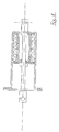
- Fig. 6 shows the pulled out by the drawbar movement damper. This corresponds to the position of the lower in Fig. 3 damper 22.
- the damper 22 has bearings 28 and 30 and a threaded rod 32 with a nut 34.
- a driver cup 36 is provided which can be loaded by a spring 38, which in turn supported in the bent ends of the driver cup 36 at one end.
- This driver cup with the spring 38 is guided in the housing 40 of the damper.
- the threaded rod passes through a drive plate 42, at the other end, the spring 38 is supported.
- the drive plate 42 in turn is supported on the bent ends of the driver cup 36, at the inside also the head end 44 of the threaded rod 32 is supported.
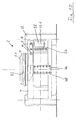
- Figs. 9 and 10 the dolly axle without drawbar is shown in a front view.
- the dolly axle is to be equipped in such a way that the drawbar is height-adjustable to be attached to the frame.
- a draw block 46 is provided, the one above the other in pairs assignment holes 48 for connection of the drawbar - not shown - has at different altitudes.
- This drawbar 46 is further part of a reverse lock, which is generally numbered 50.
- This reverse lock 50 has a pivotable stuntsperrklaue 52 which is mounted at 54 and loaded by a spring 56. About a pneumatic cylinder 58, this is to bring in the Verrastungswolf shown in Fig.
Landscapes
- Engineering & Computer Science (AREA)
- Chemical & Material Sciences (AREA)
- Combustion & Propulsion (AREA)
- Transportation (AREA)
- Mechanical Engineering (AREA)
- Automatic Cycles, And Cycles In General (AREA)
Applications Claiming Priority (2)
| Application Number | Priority Date | Filing Date | Title |
|---|---|---|---|
| DE102006044202A DE102006044202A1 (de) | 2006-09-15 | 2006-09-15 | Dolly-Achse |
| DE202006015113U DE202006015113U1 (de) | 2006-09-15 | 2006-10-02 | Dolly-Achse |
Publications (2)
| Publication Number | Publication Date |
|---|---|
| EP1900611A2 true EP1900611A2 (fr) | 2008-03-19 |
| EP1900611A3 EP1900611A3 (fr) | 2008-08-06 |
Family
ID=37833012
Family Applications (1)
| Application Number | Title | Priority Date | Filing Date |
|---|---|---|---|
| EP07013638A Withdrawn EP1900611A3 (fr) | 2006-09-15 | 2007-07-12 | Axe de dolly |
Country Status (2)
| Country | Link |
|---|---|
| EP (1) | EP1900611A3 (fr) |
| DE (1) | DE202006015113U1 (fr) |
Cited By (1)
| Publication number | Priority date | Publication date | Assignee | Title |
|---|---|---|---|---|
| CN116780299A (zh) * | 2023-08-23 | 2023-09-19 | 江苏速豹动力科技有限公司 | 电气连接装置及卡车 |
Families Citing this family (4)
| Publication number | Priority date | Publication date | Assignee | Title |
|---|---|---|---|---|
| DE102008001565A1 (de) | 2008-05-06 | 2009-11-12 | Zf Friedrichshafen Ag | Anhänger mit zumindest einer Achse und einer Sattelkupplung zur Aufnahme eines Sattelaufliegers |
| EP2634018B1 (fr) | 2012-02-29 | 2014-11-26 | Helmut Fliegl | Axe de dolly |
| EP3398842B1 (fr) | 2017-05-04 | 2020-10-28 | Helmut Fliegl | Diabolo pour système de support de selle |
| DE102020115469B4 (de) | 2020-06-10 | 2022-04-21 | Sommer Gmbh | Dolly-Anhänger, Zug-Gespann mit einem solchen Dolly-Anhänger sowie Verfahren zum Betreiben eines solchen Zug-Gespannes |
Citations (10)
| Publication number | Priority date | Publication date | Assignee | Title |
|---|---|---|---|---|
| DE646443C (de) * | 1936-04-02 | 1937-06-17 | Hans Schroeter | Mit der Anhaengerlenkvorrichtung verbundene Daempfungsvorrichtung fuer die Schleuder- oder Schlingerbewegungen an Anhaengern |
| US3063739A (en) * | 1957-09-17 | 1962-11-13 | Davies Magnet Works Ltd | Trailer fifth wheel couplings |
| CH536218A (de) * | 1972-01-25 | 1973-04-30 | Vetter Hans | Tiefladefahrzeug |
| US4281847A (en) * | 1979-08-22 | 1981-08-04 | The University Of Kentucky Research Foundation | Trailer hitch |
| DE3013780A1 (de) * | 1980-04-10 | 1981-10-15 | Hermann Peter Hall Nachf. KG, 5000 Köln | Lenkbarer kraftfahrzeuganhaenger |
| GB2181398A (en) * | 1985-09-18 | 1987-04-23 | Econ Group Ltd | Trailer draw-bar control means |
| DE19905676A1 (de) * | 1999-02-11 | 2000-08-31 | Bpw Bergische Achsen Kg | Zugdeichsel für Zentralachsanhänger |
| US6158759A (en) * | 1998-11-02 | 2000-12-12 | Perry; Duane L. | Wagon steering control mechanism |
| WO2004098981A1 (fr) * | 2003-05-08 | 2004-11-18 | Scania Cv Ab (Publ) | Remorque orientable |
| EP1466813B1 (fr) * | 2003-04-10 | 2006-06-07 | Fahrzeugwerk Bernard Krone GmbH | Axe de dolly avec train de roues orientables |
-
2006
- 2006-10-02 DE DE202006015113U patent/DE202006015113U1/de not_active Expired - Lifetime
-
2007
- 2007-07-12 EP EP07013638A patent/EP1900611A3/fr not_active Withdrawn
Patent Citations (10)
| Publication number | Priority date | Publication date | Assignee | Title |
|---|---|---|---|---|
| DE646443C (de) * | 1936-04-02 | 1937-06-17 | Hans Schroeter | Mit der Anhaengerlenkvorrichtung verbundene Daempfungsvorrichtung fuer die Schleuder- oder Schlingerbewegungen an Anhaengern |
| US3063739A (en) * | 1957-09-17 | 1962-11-13 | Davies Magnet Works Ltd | Trailer fifth wheel couplings |
| CH536218A (de) * | 1972-01-25 | 1973-04-30 | Vetter Hans | Tiefladefahrzeug |
| US4281847A (en) * | 1979-08-22 | 1981-08-04 | The University Of Kentucky Research Foundation | Trailer hitch |
| DE3013780A1 (de) * | 1980-04-10 | 1981-10-15 | Hermann Peter Hall Nachf. KG, 5000 Köln | Lenkbarer kraftfahrzeuganhaenger |
| GB2181398A (en) * | 1985-09-18 | 1987-04-23 | Econ Group Ltd | Trailer draw-bar control means |
| US6158759A (en) * | 1998-11-02 | 2000-12-12 | Perry; Duane L. | Wagon steering control mechanism |
| DE19905676A1 (de) * | 1999-02-11 | 2000-08-31 | Bpw Bergische Achsen Kg | Zugdeichsel für Zentralachsanhänger |
| EP1466813B1 (fr) * | 2003-04-10 | 2006-06-07 | Fahrzeugwerk Bernard Krone GmbH | Axe de dolly avec train de roues orientables |
| WO2004098981A1 (fr) * | 2003-05-08 | 2004-11-18 | Scania Cv Ab (Publ) | Remorque orientable |
Cited By (2)
| Publication number | Priority date | Publication date | Assignee | Title |
|---|---|---|---|---|
| CN116780299A (zh) * | 2023-08-23 | 2023-09-19 | 江苏速豹动力科技有限公司 | 电气连接装置及卡车 |
| CN116780299B (zh) * | 2023-08-23 | 2023-12-15 | 江苏速豹动力科技有限公司 | 电气连接装置及卡车 |
Also Published As
| Publication number | Publication date |
|---|---|
| DE202006015113U1 (de) | 2007-02-22 |
| EP1900611A3 (fr) | 2008-08-06 |
Similar Documents
| Publication | Publication Date | Title |
|---|---|---|
| EP1900610B1 (fr) | Axe de dolly | |
| EP1900609A2 (fr) | Axe de dolly | |
| EP0544727B1 (fr) | Vehicule | |
| EP2192026B1 (fr) | Machine de traction agricole | |
| EP1900618B1 (fr) | Axe de dolly | |
| EP0141093A2 (fr) | Suspension pour des roues avant dirigeables de véhicules automobiles | |
| DE3031862C2 (de) | Gelenkfahrzeug mit mehreren Achsen | |
| EP1466813B1 (fr) | Axe de dolly avec train de roues orientables | |
| DE2844626A1 (de) | Mechanisch spurfuehrbares strassengaengiges fahrzeug | |
| EP1900611A2 (fr) | Axe de dolly | |
| DE4227126A1 (de) | Gelenkverbindung zwischen zwei gelenkig miteinander verbundenen Fahrzeugen | |
| EP1900612A2 (fr) | Axe de dolly | |
| DE102006047456A1 (de) | Vorrichtung zur drehgelenkigen Kupplung, insbesondere von Sattelaufliegerzügen | |
| EP3398842B1 (fr) | Diabolo pour système de support de selle | |
| DE3002354C2 (de) | Zug-und Lenkvorrichtung für einen Lastzug | |
| DE3533216C2 (fr) | ||
| EP2239188B9 (fr) | Col de cygne de véhicule, notamment pour véhicule gros porteur | |
| DE3145871A1 (de) | Anhaengerkupplungsvorrichtung eines lastzuges | |
| EP0562598A1 (fr) | Assemblage à rotule entre deux véhicules articulés | |
| DE2263506A1 (de) | Steuervorrichtung fuer einen anhaengewagen | |
| EP0388363B1 (fr) | Attelage pour véhicules | |
| DE102016102318A1 (de) | Lastaufnehmender vierrädriger Anhänger für einen Schleppzug | |
| DE3328123A1 (de) | Lastzug mit einer lenkung fuer das anhaengerfahrzeug | |
| DE3004885A1 (de) | Anhaenger fuer lastkraftwagen | |
| DE102007033533B4 (de) | Sperreinrichtung einer gelenkten Achse |
Legal Events
| Date | Code | Title | Description |
|---|---|---|---|
| PUAI | Public reference made under article 153(3) epc to a published international application that has entered the european phase |
Free format text: ORIGINAL CODE: 0009012 |
|
| AK | Designated contracting states |
Kind code of ref document: A2 Designated state(s): AT BE BG CH CY CZ DE DK EE ES FI FR GB GR HU IE IS IT LI LT LU LV MC MT NL PL PT RO SE SI SK TR |
|
| AX | Request for extension of the european patent |
Extension state: AL BA HR MK YU |
|
| PUAL | Search report despatched |
Free format text: ORIGINAL CODE: 0009013 |
|
| AK | Designated contracting states |
Kind code of ref document: A3 Designated state(s): AT BE BG CH CY CZ DE DK EE ES FI FR GB GR HU IE IS IT LI LT LU LV MC MT NL PL PT RO SE SI SK TR |
|
| AX | Request for extension of the european patent |
Extension state: AL BA HR MK RS |
|
| 17P | Request for examination filed |
Effective date: 20080807 |
|
| 17Q | First examination report despatched |
Effective date: 20080926 |
|
| STAA | Information on the status of an ep patent application or granted ep patent |
Free format text: STATUS: THE APPLICATION HAS BEEN WITHDRAWN |
|
| 18W | Application withdrawn |
Effective date: 20081129 |