EP1900611A2 - Dolly axle - Google Patents
Dolly axle Download PDFInfo
- Publication number
- EP1900611A2 EP1900611A2 EP07013638A EP07013638A EP1900611A2 EP 1900611 A2 EP1900611 A2 EP 1900611A2 EP 07013638 A EP07013638 A EP 07013638A EP 07013638 A EP07013638 A EP 07013638A EP 1900611 A2 EP1900611 A2 EP 1900611A2
- Authority
- EP
- European Patent Office
- Prior art keywords
- drawbar
- dolly axle
- axle according
- dolly
- damper
- Prior art date
- Legal status (The legal status is an assumption and is not a legal conclusion. Google has not performed a legal analysis and makes no representation as to the accuracy of the status listed.)
- Withdrawn
Links
Images


Classifications
-
- B—PERFORMING OPERATIONS; TRANSPORTING
- B62—LAND VEHICLES FOR TRAVELLING OTHERWISE THAN ON RAILS
- B62D—MOTOR VEHICLES; TRAILERS
- B62D53/00—Tractor-trailer combinations; Road trains
- B62D53/04—Tractor-trailer combinations; Road trains comprising a vehicle carrying an essential part of the other vehicle's load by having supporting means for the front or rear part of the other vehicle
- B62D53/08—Fifth wheel traction couplings
- B62D53/0857—Auxiliary semi-trailer handling or loading equipment, e.g. ramps, rigs, coupling supports
- B62D53/0864—Dollies for fifth wheel coupling
-
- B—PERFORMING OPERATIONS; TRANSPORTING
- B62—LAND VEHICLES FOR TRAVELLING OTHERWISE THAN ON RAILS
- B62D—MOTOR VEHICLES; TRAILERS
- B62D13/00—Steering specially adapted for trailers
- B62D13/04—Steering specially adapted for trailers for individually-pivoted wheels
-
- B—PERFORMING OPERATIONS; TRANSPORTING
- B62—LAND VEHICLES FOR TRAVELLING OTHERWISE THAN ON RAILS
- B62D—MOTOR VEHICLES; TRAILERS
- B62D13/00—Steering specially adapted for trailers
- B62D13/06—Steering specially adapted for trailers for backing a normally drawn trailer
Definitions
- the invention relates to a dolly axle with a drawbar rotatably mounted on a frame about a vertical axis and a saddle dome arranged on the upper side of the frame and at least one wheelset which is steerable by the pivoting movement of the drawbar transmitted transmission means, preferably at least one as transmission means Steering arm is provided, with which the pivoting movement of the drawbar is transferable to at least one steering lever acting on the steerable wheelset and in particular the position of the shift control arm is variable by driven adjusting means.
- Such a dolly axis is from the EP 1 466 813 B known.
- a link arm having intermediate levers are provided as transmission means with which the pivoting movement of the drawbar on steering levers, which act on the steerable wheelset, can be transmitted.
- the position of the intermediate lever is variable by driven adjusting means, so that the inevitably resulting in steering movements pivotal movement of the drawbar can be used to initiate a steering angle of a steerable wheelset via the steering handlebar.
- the drawbar is connected to the frame, that the vertical pivot axis intersects the wheel axle of the steerable wheelset centered.
- motor drives and gearbox simple mechanical components can be used in this known dolly axle, wherein by the pivoting movement of the drawbar a steering angle is predetermined, which is transmitted by the control links according to the steerable wheelset.
- a steering angle is predetermined, which is transmitted by the control links according to the steerable wheelset.
- the geometry of the transmission means is changed.
- steering movements arise in different positions of the shift handlebars different strong steering movements at the same steering angle of the drawbar.
- a switching position of the control arm so less steering movements can be transmitted to a steerable wheelset, for example, at low shunting speeds of the drawbar, while in another switching position of the control arm at, for example, higher speeds transmitted by the drawbar parking paths at the same angle of the drawbar are greater.
- the dolly axle of the type mentioned is characterized by the fact that the pivot axis of the drawbar is located in the forward direction of the wheel axle of the wheelset, which absorbs the prevailing tensile load, which is accompanied even after extended periods of use a more balanced and quiet running.
- the adjusting lever is variable in position on the drawbar pivotally fixed and that the adjusting lever and the steering correction lever are variable in position to each other can be fixed.
- a steering geometry is implemented in the dolly axle, in which a steering angle correction can be carried out, preferably in cooperation with a steering damper and a rotatable saddle dome, which will be presented in more detail below.
- the steering angle of the inner and outer wheels is adapted to the actual existing angles of the curves or circular drive. This is accompanied by a lower tire wear and a rolling resistance minimization.
- the adjusting lever is provided, on which a steering lever hingedly engages, which in turn is pivotally connected to the handlebar. Due to the distance ratios of the articulation points provided in this case, the corresponding steering angle correction can be performed.
- the spacing conditions are adjustable and thus changeable.
- the shift control arm swivel axes which are located in the forward direction of travel in front of the pivot axis of the drawbar.
- the drawbar is supported on at least one damper on the frame.
- a dolly axle is provided in which rolling movements and also a rocking of the vehicle combination are to be significantly reduced overall.
- the damper is always in use, so that there is always a damped state of the drawbar even with different angles of the drawbar.
- two dampers are provided, each in the direction of travel right and left - based on the center position of the drawbar - attack on this one end and the other end are supported on the frame.
- Preferred dimensions of the respective damper is a component having a threaded rod, a driver cup, a housing and an inner spring, wherein the threaded rod relative to the driver cup and the housing and the driver cup are movable relative to the housing.
- This can take various positions for the drawbar, namely once a middle position in which no force is built, and respective end positions with inserted driver cup and retracted threaded rod and a respective extended position of the threaded rod in the inside displacement of the driver cup together with the spring and of course corresponding intermediate positions ,
- the neutral position ie the center position of the drawbar, the bearing of the threaded rod is unloaded, wherein it comes in the respective end positions to a load on the threaded rod in the corresponding bearing points, which counteracts any rolling movements.
- the fifth wheel plate is preferably limited in terms of its rotational movement or with respect to its rotation.
- the saddle plate or the saddle dome is rotatably mounted, so incurred by a friction between saddle dome and semi-trailer low frictional forces. Larger occurring friction forces would cause a rocking of the vehicle combination.
- an intended tie rod or handlebar the coupling process without manual intervention is possible.
- the use of standard axes is possible. In combination with the steering damper and the rotatable saddle dome swinging is effectively prevented.
- the dampers which attack both sides of the drawbar, a provision of the drawbar in the neutral position is possible.
- an end stop is also provided on the frame in order to limit the maximum deflection of the drawbar.
- a reverse lock is also provided, in which via a connectable to the drawbar spring-loaded vomfahrsperrklaue the drawbar is locked, in its neutral position.
- This reverse lock can be operated via a cylinder.
- the drawbar is adjustable in height connected to the frame, including a mounting arrangement is provided with superposed mounting holes.
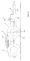
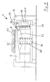
- Fig. 1 is a side view of a dolly axis 2 can be seen.
- the dolly axle 2 has a frame 4, a drawbar 6, a fifth wheel 8, a steerable wheel set 10 and a non-steerable wheel set 12 with a wheel axle 12.1.
- the drawbar 6 is formed in two parts and has a front drawbar part 6.1 and a rear, connected to the frame 4 drawbar part 6.2.
- the drawbar 6 can be attached with its front end to a trailer hitch of a towing vehicle.
- the shape of the drawbar is not limited to the embodiment shown in the embodiment, but may also have other shapes, such as a gooseneck drawbar.
- a semi-trailer can be firmly connected to the fifth wheel 8.
- the corresponding truck can have additional cargo space, which is arranged for example on the towing vehicle.
- the drawbar is about a pivot axis 14, which is located in order to achieve a smooth running even after prolonged periods of use in front of the wheel axle 12.1, pivotally, as is apparent from Fig. 2 in more detail.
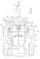
- the dolly axle 2 can be seen from a top view, in a position in which the drawbar 6 is with its front part 6.1 and its rear part 6.2 in its neutral position for a straight ahead. Due to the two-part drawbar the simple possibility is created to equip the vehicle for both low and normal dome heights.
- the fifth wheel 8 is arranged approximately centrally between the steerable wheelset 10 and the non-steerable wheelset 12.
- the dolly axis 2 is thus shown as Zweiachsaus exit, but can also be equipped and used as a one-axis or more than two axes accordingly.
- the steering levers 16 can be seen on which attack in detail not shown transmission means. These are spaced from the axis of rotation of the steering joint arranged to use a lever travel for the adjustment of the steering angle can.
- the transmission means consist in the embodiment of a shift link 18 and a tie rod 18.
- a shift link 18 is provided which engages articulated at 20 to the drawbar 6.
- the pivot axes 20 are located in the forward direction in front of the pivot axis 14 of the drawbar, which in turn, due to the always existing tensile load advantageously has an effect on the smooth running of the dolly axle and in the case of worn bearings.
- each end stop 24 is provided on the frame 4.
- These steering bar stops 24 prevent excessive steering of a vehicle combination.
- These can also be equipped so that when a stop of the drawbar 6 on the stop 24, an optical or acoustic signal is generated for a corresponding driver information.
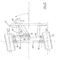
- Fig. 3 is a maximum traction drawbar 6 is otherwise illustrated with an analogous structure as in the embodiment of FIG. 2.
- the drawbar 6 is located at the top stop 24 in the drawing. In the embodiment shown, this corresponds to a drawbar maximum angle of 33 °.
- the drawbar movement has been transferred to the steerable wheelset 12.
- the drawbar has been moved against the attacking damper 22, so that the upper damper 22 is retracted in FIG. 3 and the lower damper 22 is extended in FIG. 3.
- the saddle crest 8 arranged on the frame 4 has a rotatable saddle plate 8.1, which interacts with rotational stops 8.2. These act as end stops and minimize the friction between the fifth wheel and a semi-trailer. As a result, a lurching and rocking of the vehicle combination is prevented.
- the fifth wheel end stops 8.2 allow the coupling to be done without manual intervention since the possible angle of rotation is chosen so that when coupling semi-trailers to the dolly axle, the centering aid of the fifth wheel without manual intervention by the driver e.g. by setting the fifth wheel, the kingpin usually provided leads correctly and thus a safe and correct connection can be made.
- the upper angle ⁇ is approximately 10 ° and the lower angle ⁇ is approximately 8 °.
- the adjustment lever is adjustable by a dimension S of about 80 mm, whereby an integrated steering angle correction of +/- 2 ° is possible to adjust the steering angle of the inside and outside steering angle to the radius of cornering. This results in a lower tire wear, a lower rolling resistance, a lower consumption, a lower load on the axles and the steering device, for example in the bearings and the track and handlebars, the steering angle correction at job sites and applications is adaptable. This is realized by the chosen solution in a structurally very simple way.
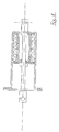
- Fig. 6 shows the pulled out by the drawbar movement damper. This corresponds to the position of the lower in Fig. 3 damper 22.
- the damper 22 has bearings 28 and 30 and a threaded rod 32 with a nut 34.
- a driver cup 36 is provided which can be loaded by a spring 38, which in turn supported in the bent ends of the driver cup 36 at one end.
- This driver cup with the spring 38 is guided in the housing 40 of the damper.
- the threaded rod passes through a drive plate 42, at the other end, the spring 38 is supported.
- the drive plate 42 in turn is supported on the bent ends of the driver cup 36, at the inside also the head end 44 of the threaded rod 32 is supported.
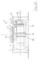
- Figs. 9 and 10 the dolly axle without drawbar is shown in a front view.
- the dolly axle is to be equipped in such a way that the drawbar is height-adjustable to be attached to the frame.
- a draw block 46 is provided, the one above the other in pairs assignment holes 48 for connection of the drawbar - not shown - has at different altitudes.
- This drawbar 46 is further part of a reverse lock, which is generally numbered 50.
- This reverse lock 50 has a pivotable stuntsperrklaue 52 which is mounted at 54 and loaded by a spring 56. About a pneumatic cylinder 58, this is to bring in the Verrastungswolf shown in Fig.
Abstract
Description
Die Erfindung betrifft eine Dolly-Achse mit einer an einem Rahmen um eine vertikale Achse drehbeweglich befestigten Zugdeichsel und einer auf der Oberseite des Rahmens angeordneten Sattelkuppel sowie zumindest einem Radsatz, der von die Schwenkbewegung der Zugdeichsel übertragenen Übertragungsmitteln lenkbar ist, wobei vorzugsweise als Übertragungsmittel zumindest ein Schaltlenker vorgesehen ist, mit dem die Schwenkbewegung der Zugdeichsel auf wenigstens einen auf den lenkbaren Radsatz wirkenden Lenkhebel übertragbar ist und insbesondere die Lage des Schaltlenkers durch angetriebene Stellmittel veränderbar ist.The invention relates to a dolly axle with a drawbar rotatably mounted on a frame about a vertical axis and a saddle dome arranged on the upper side of the frame and at least one wheelset which is steerable by the pivoting movement of the drawbar transmitted transmission means, preferably at least one as transmission means Steering arm is provided, with which the pivoting movement of the drawbar is transferable to at least one steering lever acting on the steerable wheelset and in particular the position of the shift control arm is variable by driven adjusting means.
Eine derartige Dolly-Achse ist aus der
Anstelle von aufwändigen und defektanfälligen Sensoren, motorischen Antrieben und Getriebe können bei dieser vorbekannten Dolly-Achse einfache mechanische Komponenten eingesetzt werden, wobei durch die Schwenkbewegung der Zugdeichsel ein Lenkwinkel vorgegeben ist, der von den Schaltlenkern entsprechend auf den lenkbaren Radsatz übertragen wird. Durch die Übertragung der Lenkbewegung der Zugdeichsel auf einen lenkbaren Radsatz kann der auf der Dolly-Achse aufliegende Anhänger in einem günstigen, von den Lenkbewegungen beeinflußten Radius um eine von der Zugmaschine gefahrene Kurve herumbewegt werden. Durch die Lenkung der Dolly-Achse sind insgesamt kleinere Wenderadien ermöglicht.Instead of complex and fault-prone sensors, motor drives and gearbox simple mechanical components can be used in this known dolly axle, wherein by the pivoting movement of the drawbar a steering angle is predetermined, which is transmitted by the control links according to the steerable wheelset. By transferring the steering movement of the drawbar to a steerable wheelset, the trailer resting on the dolly axle can be moved about a radius driven by the steering movements about a corner driven by the tractor. Due to the steering of the dolly axle altogether smaller turning radii are possible.
Durch eine Veränderung der Lage des Schaltlenkers wird die Geometrie der Übertragungsmittel verändert. Bei Lenkbewegungen ergeben sich in unterschiedlichen Stellpositionen des Schaltlenkers unterschiedlich starke Lenkbewegungen bei gleichem Einschlagwinkel der Zugdeichsel. In einer Schaltposition des Schaltlenkers können also beispielsweise bei niedrigen Rangiergeschwindigkeiten von der Zugdeichsel geringere Lenkbewegungen auf einen lenkbaren Radsatz übertragen werden, während in einer anderen Schaltposition des Schaltlenkers bei beispielsweise höheren Geschwindigkeiten die von der Zugdeichsel übertragenen Stellwege bei gleichem Winkel der Zugdeichsel größer sind. Bei der vorbekannten Dolly-Achse ist es daher möglich, mit kostengünstigen Stellelementen geschwindigkeitsabhängig unterschiedlich starke Lenkimpulse auf einen lenkbaren Radsatz zu übertragen.By changing the position of the shift control arm, the geometry of the transmission means is changed. When steering movements arise in different positions of the shift handlebars different strong steering movements at the same steering angle of the drawbar. In a switching position of the control arm so less steering movements can be transmitted to a steerable wheelset, for example, at low shunting speeds of the drawbar, while in another switching position of the control arm at, for example, higher speeds transmitted by the drawbar parking paths at the same angle of the drawbar are greater. In the known dolly axle, it is therefore possible to transfer with low-cost actuators speed-dependent different strong steering pulses on a steerable wheelset.
Bei allen Vorteilen dieser vorbekannten Dolly-Achse ist allerdings zu beobachten, daß insbesondere bei sehr langen Fahrzeugkombinationen noch Schlingerbewegungen und ein Aufschaukeln der Fahrzeugkombination zu beobachten ist. Insbesondere nach längeren Gebrauchszeiten kann sich auch bei ausgeschlagenen Lagern im Bereich der Zugdeichsel ein unruhiger Lauf ergeben. Hier setzt die vorliegende Erfindung an, der die Aufgabe zugrunde liegt, bei Beibehaltung der Vorteile der vorgenannten Dolly-Achse das Laufverhalten noch weiter zu verbessern.With all the advantages of this known dolly axle, however, it can be observed that, in particular in the case of very long vehicle combinations, rolling movements and rocking of the vehicle combination can still be observed. In particular, after extended periods of use, even with knocked out bearings in the area of the drawbar, a restless run can result. This is where the present invention is based, which is based on the object to further improve the running behavior while maintaining the advantages of the aforementioned dolly axis.
Zur Lösung dieser Aufgabe zeichnet sich die Dolly-Achse der eingangs genannten Art dadurch aus, daß die Schwenkachse der Zugdeichsel in Vorwärtsfahrtrichtung vor der Radachse des Radsatzes gelegen ist, der die vorherrschende Zugbelastung aufnimmt, womit auch nach längeren Gebrauchszeiten ein vergleichmäßigter und ruhiger Lauf einhergeht. Vorteilweise greift an dem Lenkhebel gelenkig ein Schaltlenker an, der an einem Verstellhebel gelenkig angreift, der seinerseits über einen Lenkkorrekturhebel verstellbar ist. Vorteilhafterweise ist vorgesehen, daß der Verstellhebel lageveränderlich an der Zugdeichsel schwenkbeweglich festlegbar ist und daß der Verstellhebel und der Lenkkorrekturhebel lageveränderlich aneinander festlegbar sind.To solve this problem, the dolly axle of the type mentioned is characterized by the fact that the pivot axis of the drawbar is located in the forward direction of the wheel axle of the wheelset, which absorbs the prevailing tensile load, which is accompanied even after extended periods of use a more balanced and quiet running. Advantageously engages the steering arm articulated to a handlebar, which articulates on an adjusting lever, which in turn is adjustable via a steering correction lever. Advantageously, it is provided that the adjusting lever is variable in position on the drawbar pivotally fixed and that the adjusting lever and the steering correction lever are variable in position to each other can be fixed.
Dadurch ist bei der Dolly-Achse eine Lenkgeometrie realisiert, bei der eine Lenkwinkelkorrektur durchgeführt werden kann, und zwar bevorzugt in Zusammenwirken mit einem Lenkungsdämpfer und einer drehbaren Sattelkuppel, die im weiteren noch näher vorgestellt werden. Dabei wird der Lenkwinkel der innen- und außenliegenden Räder an die real vorhandenen Winkel der Kurven bzw. Kreisfahrt angepaßt. Damit geht ein geringerer Reifenverschleiß sowie eine Rollwiderstandsminimierung einher. Dazu ist der Verstellhebel vorgesehen, an dem ein Lenkhebel gelenkig angreift, der seinerseits gelenkig mit dem Schaltlenker verbunden ist. Aufgrund der dabei vorgesehenen Abstandsverhältnisse der Anlenkpunkte kann die entsprechende Lenkwinkelkorrektur durchgeführt werden. Bevorzugt sind die Abstandsverhältnisse einstellbar und damit veränderbar.As a result, a steering geometry is implemented in the dolly axle, in which a steering angle correction can be carried out, preferably in cooperation with a steering damper and a rotatable saddle dome, which will be presented in more detail below. The steering angle of the inner and outer wheels is adapted to the actual existing angles of the curves or circular drive. This is accompanied by a lower tire wear and a rolling resistance minimization. For this purpose, the adjusting lever is provided, on which a steering lever hingedly engages, which in turn is pivotally connected to the handlebar. Due to the distance ratios of the articulation points provided in this case, the corresponding steering angle correction can be performed. Preferably, the spacing conditions are adjustable and thus changeable.
Um den Lauf auch nach längeren Gebrauchszeiten und z.B. auch bei ausgeschlagenen Lagern noch weiter zu vergleichmäßigen, ist darüber hinaus bevorzugt vorgesehen, daß die Schaltlenker Schwenkachsen haben, die in Vorwärtsfahrtrichtung vor der Schwenkachse der Zugdeichsel gelegen sind.In order to even further even after prolonged periods of use and, for example, even with worn bearings even further, it is preferably provided that the shift control arm swivel axes, which are located in the forward direction of travel in front of the pivot axis of the drawbar.
In vorteilhafter Weise ist die Zugdeichsel über zumindest einen Dämpfer an dem Rahmen abstützbar. Damit ist eine Dolly-Achse zur Verfügung gestellt, bei der Schlingerbewegungen und auch ein Aufschaukeln der Fahrzeugkombination insgesamt wesentlich zu reduzieren sind. Der Dämpfer ist immer im Einsatz, so daß es auch bei unterschiedlichen Einschlagwinkeln der Zugdeichsel immer einen gedämpften Zustand der Zugdeichsel gibt. Vorzugsweise sind zwei Dämpfer vorgesehen, die jeweils in Fahrtrichtung rechts und links - bezogen auf die Mittelstellung der Zugdeichsel - an dieser einenends angreifen und sich anderenends am Rahmen abstützen.Advantageously, the drawbar is supported on at least one damper on the frame. Thus, a dolly axle is provided in which rolling movements and also a rocking of the vehicle combination are to be significantly reduced overall. The damper is always in use, so that there is always a damped state of the drawbar even with different angles of the drawbar. Preferably, two dampers are provided, each in the direction of travel right and left - based on the center position of the drawbar - attack on this one end and the other end are supported on the frame.
Bevorzugtermaßen ist der jeweilige Dämpfer ein Bauteil, das eine Gewindestange, einen Mitnehmertopf, ein Gehäuse sowie eine innenliegende Feder aufweist, wobei die Gewindestange relativ zum Mitnehmertopf und dem Gehäuse sowie der Mitnehmertopf relativ zu dem Gehäuse beweglich sind. Damit lassen sich verschiedene Stellungen für die Zugdeichsel einnehmen, nämlich einmal eine Mittelstellung, in der keine Kraft aufgebaut ist, und jeweilige Endstellungen mit eingeschobenem Mitnehmertopf und eingezogener Gewindestange und einer jeweils ausgezogenen Position der Gewindestange bei innenseitige Verlagerung des Mitnehmertopfes mitsamt der Feder und selbstverständlich entsprechende Zwischenstellungen. In der Neutralstellung, also der Mittelstellung der Zugdeichsel, ist das Lager der Gewindestange unbelastet, wobei es in den jeweiligen Endstellungen zu einer Belastung an der Gewindestange in den entsprechenden Lagerstellen kommt, die etwaigen Schlingerbewegungen entgegenwirkt.Preferred dimensions of the respective damper is a component having a threaded rod, a driver cup, a housing and an inner spring, wherein the threaded rod relative to the driver cup and the housing and the driver cup are movable relative to the housing. This can take various positions for the drawbar, namely once a middle position in which no force is built, and respective end positions with inserted driver cup and retracted threaded rod and a respective extended position of the threaded rod in the inside displacement of the driver cup together with the spring and of course corresponding intermediate positions , In the neutral position, ie the center position of the drawbar, the bearing of the threaded rod is unloaded, wherein it comes in the respective end positions to a load on the threaded rod in the corresponding bearing points, which counteracts any rolling movements.
Des weiteren ist bevorzugterweise die Sattelplatte hinsichtlich ihrer Drehbewegung bzw. hinsichtlich ihrer Rotation begrenzt. Die Sattelplatte bzw. die Sattelkuppel ist drehbar gelagert, damit durch eine Reibung zwischen Sattelkuppel und Sattelauflieger geringe Reibungskräfte anfallen. Größere auftretende Reibungskräfte würden ein Aufschaukeln der Fahrzeugkombination bewirken. Durch eine vorgesehene Spurstange bzw. Lenkstange ist der Kupplungsvorgang ohne manuelle Eingriffe möglich. Dabei ist die Verwendung von Standardachsen möglich. ln Kombination mit dem Lenkungsdämpfer und der drehbaren Sattelkuppel ist ein Aufschaukeln wirksam verhindert. Durch die Dämpfer, die beidseits der Zugdeichsel angreifen, ist auch eine Rückstellung der Zugdeichsel in die Neutralstellung möglich. Vorteilhafterweise ist ebenfalls noch ein Endanschlag an dem Rahmen vorgesehen, um die maximale Auslenkung der Zugdeichsel zu begrenzen.Furthermore, the fifth wheel plate is preferably limited in terms of its rotational movement or with respect to its rotation. The saddle plate or the saddle dome is rotatably mounted, so incurred by a friction between saddle dome and semi-trailer low frictional forces. Larger occurring friction forces would cause a rocking of the vehicle combination. By an intended tie rod or handlebar the coupling process without manual intervention is possible. The use of standard axes is possible. In combination with the steering damper and the rotatable saddle dome swinging is effectively prevented. By the dampers, which attack both sides of the drawbar, a provision of the drawbar in the neutral position is possible. Advantageously, an end stop is also provided on the frame in order to limit the maximum deflection of the drawbar.
Bevorzugterweise ist auch noch eine Rückfahrsperre vorgesehen, bei der über eine mit der Zugdeichsel verbindbare federbelastete Rückfahrsperrklaue die Zugdeichsel verriegelbar ist, und zwar in ihrer Neutralstellung. Diese Rückfahrsperre kann über einen Zylinder zu betätigen sein. Des weiteren kann vorgesehen sein, daß die Zugdeichsel höhenverstellbar mit dem Rahmen verbindbar ist, wozu eine Befestigungsanordnung mit übereinander angeordneten Befestigungslöchern vorgesehen ist.Preferably, a reverse lock is also provided, in which via a connectable to the drawbar spring-loaded Rückfahrsperrklaue the drawbar is locked, in its neutral position. This reverse lock can be operated via a cylinder. Furthermore, it can be provided that the drawbar is adjustable in height connected to the frame, including a mounting arrangement is provided with superposed mounting holes.
Weitere vorteilhafte Ausgestaltungen der Erfindung ergeben sich aus weiteren Unteransprüchen, der nachfolgenden Beschreibung und der Zeichnung. In der Zeichnung zeigen:
- Fig. 1
- Seitenansicht eines Ausführungsbeispiels einer Dolly-Achse,
- Fig. 2
- eine Draufsicht auf das Ausführungsbeispiel nach Fig. 1 in der Neutralstellung der Zugdeichsel,
- Fig. 3
- eine Ansicht von oben auf das Ausführungsbeispiel nach Fig. 1 mit eingeschlagener Zugdeichsel;
- Fig. 4
- einen Ausschnitt der Darstellung nach Fig. 2 ohne Darstellung von Dämpferelementen, aber mit Darstellung einer Lenkwinkelkorrektur,
- Fig. 5
- eine zu Fig. 4 analoge Darstellung mit eingeschlagener Zugdeichsel,
- Fig. 6
- in einer teilweise geschnittenen Querschnittsdarstellung ein Ausführungsbeispiel eines Dämpferelementes im ausgezogenen Zustand,
- Fig. 7
- das Ausführungsbeispiel nach Fig. 6 in Neutralstellung der Zugdeichsel,
- Fig. 8
- das Ausführungsbeispiel nach den Fig. 6 und 7 im eingeschobenen Zustand des Dämpfers,
- Fig. 9
- eine Ansicht von vorne auf die Dolly-Achse mit eingerasteter Rückfahrsperrklaue, und
- Fig. 10
- eine zu Fig. 9 analoge Darstellung mit entriegelter Rückfahrsperrklaue.
- Fig. 1
- Side view of an embodiment of a dolly axle,
- Fig. 2
- a plan view of the embodiment of Figure 1 in the neutral position of the drawbar,
- Fig. 3
- a top view of the embodiment of Figure 1 with taken drawbar.
- Fig. 4
- 2 shows a detail of the representation according to FIG. 2 without representation of damper elements, but with representation of a steering angle correction, FIG.
- Fig. 5
- a representation analogous to FIG. 4 with the drawbar turned on,
- Fig. 6
- in a partially sectioned cross-sectional view of an embodiment of a damper element in the extended state,
- Fig. 7
- the embodiment of FIG. 6 in the neutral position of the drawbar,
- Fig. 8
- the embodiment of FIGS. 6 and 7 in the inserted state of the damper,
- Fig. 9
- a view from the front on the dolly axle with latched Rückfahrsperrklaue, and
- Fig. 10
- an analogous to Fig. 9 representation with unlocked Rückfahrsperrklaue.
In der Zeichnung sind grundsätzlich gleichwirkende Teile mit übereinstimmenden Bezugsziffern bezeichnet.In the drawing, basically equivalent parts are designated by matching reference numerals.
In Fig. 1 ist eine Seitenansicht einer Dolly-Achse 2 ersichtlich. Die Dolly-Achse 2 weist einen Rahmen 4, eine Zugdeichsel 6, eine Sattelkupplung 8, einen lenkbaren Radsatz 10 und einen nicht lenkbaren Radsatz 12 mit einer Radachse 12.1 auf. Die Zugdeichsel 6 ist zweigeteilt ausgebildet und hat einen vorderen Zugdeichselteil 6.1 und einen hinteren, mit dem Rahmen 4 verbundenen Zugdeichselteil 6.2. Die Zugdeichsel 6 ist mit ihrem vorderen Ende an einer Anhängekupplung eines Zugfahrzeuges anhängbar. Die Form der Zugdeichsel ist nicht auf die im Ausführungsbeispiel gezeigte Ausführung beschränkt, sondern kann auch andere Formgestaltungen aufweisen, wie beispielsweise eine Schwanenhalsdeichsel. Ein Sattelaufliegeranhänger kann mit der Sattelkupplung 8 fest verbunden werden. Auf diese Weise ist es möglich, ein Gespann bzw. eine Fahrzeugkombination zu realisieren, dessen Gesamtlänge bis zu 25 Metern betragen kann, Neben dem Laderaum des Sattelaufliegeranhängers kann der entsprechende Lastzug über zusätzlichen Laderaum verfügen, der beispielsweise auf dem Zugfahrzeug angeordnet ist.In Fig. 1 is a side view of a
Die Zugdeichsel ist um eine Schwenkachse 14, die zwecks Erreichens eines ruhigen Laufes auch nach längeren Gebrauchszeiten vor der Radachse 12.1 gelegen ist, schwenkbar, wie dies näher aus Fig. 2 hervorgeht. In dieser Fig. 2 ist die Dolly-Achse 2 aus einer Ansicht von oben zu sehen, und zwar in einer Stellung, in der sich für eine Geradeausfahrt die Zugdeichsel 6 mit ihrem vorderen Teil 6.1 und ihrem hinteren Teil 6.2 in ihrer Neutralstellung befindet. Durch die Zweiteiligkeit der Zugdeichsel ist die einfache Möglichkeit geschaffen, das Fahrzeug sowohl für Tief- als auch für Normalkuppelhöhen auszurüsten.The drawbar is about a
Die Sattelkupplung 8 ist etwa mittig zwischen dem lenkbaren Radsatz 10 und dem nicht lenkbaren Radsatz 12 angeordnet. Im Ausführungsbeispiel ist die Dolly-Achse 2 also als Zweiachsausführung gezeigt, kann aber auch als Einachs- oder mehr als zwei Achsen entsprechend ausgerüstet und eingesetzt werden.The
In den Fig. 2 und 3 sind die Lenkhebel 16 ersichtlich, an denen im einzelnen nicht gezeigte Übertragungsmittel angreifen. Diese sind beabstandet zur Drehachse des Lenkgelenks angeordnet, um einen Hebelweg für die Verstellung des Lenkeinschlages nutzen zu können. Die Übertragungsmittel bestehen im Ausführungsbeispiel aus einem Schaltlenker 18 bzw. einer Spurstange 18. Für jede Radseite ist ein entsprechender Schaltlenker 18 vorgesehen, der gelenkig bei 20 an der Zugdeichsel 6 angreift. Die Schwenkachsen 20 sind in Vorwärtsfahrtrichtung vor der Schwenkachse 14 der Zugdeichsel gelegen, was sich wiederum aufgrund der stets dadurch vorliegenden Zugbelastung vorteilhaft auswirkt auf den ruhigen Lauf der Dolly-Achse und im Fall von ausgeschlagenen Lagern. Jeweils in Fahrtrichtung F den Schaltlenkern 18 vorgeordnet sind jeweils zwei Dämpfer 22, die einerseits gelenkig an dem Rahmen 4 und andererseits gelenkig an der Zugdeichsel 6 angreifen. Für die Zugdeichsel 6 ist am Rahmen 4 jeweils ein Endanschlag 24 vorgesehen. Diese Lenkdeichselanschläge 24 verhindern ein zu starkes Einlenken einer Fahrzeugkombination. Diese können auch so ausgerüstet werden, daß bei einem Anschlag der Zugdeichsel 6 an dem Anschlag 24 ein optisches oder akustisches Signal erzeugt wird für eine entsprechende Fahrerinformation.In Figs. 2 and 3, the steering levers 16 can be seen on which attack in detail not shown transmission means. These are spaced from the axis of rotation of the steering joint arranged to use a lever travel for the adjustment of the steering angle can. The transmission means consist in the embodiment of a
In Fig. 3 ist eine maximal eingeschlagene Zugdeichsel 6 bei ansonsten analogem Aufbau wie in dem Ausführungsbeispiel nach Fig. 2 veranschaulicht. Die Zugdeichsel 6 befindet sich am in der Zeichnung oberen Anschlag 24. Im gezeigten Ausführungsbeispiel entspricht dies einem Zugdeichselmaximalwinkel von 33°. Über den Lenkhebel 16 und den Schaltlenker 18 ist die Zugdeichselbewegung auf den lenkbaren Radsatz 12 übertragen worden. Die Zugdeichsel ist dabei gegen die an dieser angreifenden Dämpfer 22 bewegt worden, so daß der in Fig. 3 obere Dämpfer 22 eingefahren ist und der in der Fig. 3 untere Dämpfer 22 ausgefahren ist. Diese entsprechenden Dämpfstellungen sind in den Fig. 6, 7 und 8 näher veranschaulicht, worauf noch einzugehen ist.In Fig. 3 is a
Wie ebenfalls aus den Fig. 2 und 3 ersichtlich ist, hat die auf dem Rahmen 4 angeordnete Sattelkuppe 8 eine drehbare Sattelplatte 8.1, die mit Rotationsanschlägen 8.2 zusammenwirkt. Diese wirken als Endanschläge und minimieren die Reibung zwischen Sattelkupplung und einem Sattelauflieger. Dadurch wird ein Schlingern und Aufschaukeln der Fahrzeugkombination verhindert. Durch die Sattelkupplungsendanschläge 8.2 kann der Kuppelvorgang ohne manuellen Eingriff erfolgen, da der mögliche Verdrehwinkel so gewählt ist, daß beim Kuppeln von Sattelauflieger mit der Dolly-Achse die Zentrierhilfe der Sattelkupplung ohne manuellen Eingriff durch den Fahrer, z.B. durch ein Festsetzen der Sattelkupplung, den üblicherweise vorgesehenen Königszapfen korrekt führt und somit eine sichere und korrekte Verbindung hergestellt werden kann.As can also be seen from FIGS. 2 and 3, the
ln Fig. 4 und 5 ist ausschnittsweise ein alternatives Ausführungsbeispiel zu den Ausführungsbeispielen nach Fig. 1 bis 3 dargestellt. Hier sind entsprechende Dämpfer nicht eingezeichnet, können und sollen aber bevorzugt dort vorgesehen werden. Zusätzlich ist hier eine Lenkgeometrie mit einer Lenkwinkelkorrektur dargestellt. Dazu ist der Schalthebel 18 bzw. die Spurstange 18 gelenkig mit einem Verstellhebel 26 verbunden, der wiederum gelenkig bei 26.1 mit der Zugdeichsel 6 und gelenkig bei 28.1 mit einem Lenkkorrekturhebel 28 verbunden ist, der seinerseits an dem Rahmen 4 angelenkt ist. Die Gelenkstellen 26.1.und 28.1 können verstellbar ausgebildet sein. In Fig. 4 ist die Neutralstellung der Zugdeichsel 6 dargestellt, wohingegen in Fig. 5 die Zugdeichsel am oberen Anschlag 24 liegt und sich in ihrer maximal verschwenkten Lage befindet. Bei der in Fig. 5 ersichtlichen Kurvenfahrt beträgt der obere Winkel α ca 10° und der unteren Winkel β ca 8°. Der Verstellhebel ist um ein Maß S von ca. 80 mm verstellbar, wodurch eine integrierte Lenkwinkelkorrektur von +/- 2° ermöglicht ist, um den Lenkwinkel der innen und außen liegenden Lenkwinkel an die Radien der Kurvenfahrt anzupassen. Dadurch ergibt sich ein geringerer Reifenverschleiß, ein geringerer Rollwiderstand, ein geringerer Verbrauch, eine geringere Belastung der Achsen und der Lenkeinrichtung z.B. in den Lagerstellen und der Spur- und Lenkstangen, wobei die Lenkwinkelkorrektur an Einsatzorte und an Einsatzgebiete anpaßbar ist. Dies ist durch die gewählte Lösung auf eine baulich sehr einfache Art realisiert.Referring to Figures 4 and 5, there is shown in fragmentary form an alternative embodiment to the embodiments of Figures 1-3. Here corresponding dampers are not shown, but can and should preferably be provided there. In addition, a steering geometry with a steering angle correction is shown here. For this purpose, the
In den Fig. 6 bis 8 ist im einzelnen näher ein Ausführungsbeispiel eines Dämpfers 22 dargestellt. Fig. 6 zeigt den durch die Zugdeichselbewegung ausgezogenen Dämpfer. Dies entspricht der Stellung des in Fig. 3 unteren Dämpfers 22. Der Dämpfer 22 hat Lagerstellen 28 und 30 sowie eine Gewindestange 32 mit einer Mutter 34. Des weiteren ist ein Mitnehmertopf 36 vorgesehen, der von einer Feder 38 belastet werden kann, die sich ihrerseits in den umgebogenen Enden des Mitnehmertopfes 36 einenends abstützt. Dieser Mitnehmertopf mit der Feder 38 ist in dem Gehäuse 40 des Dämpfers geführt. Des weiteren durchsetzt die Gewindestange eine Mitnehmerscheibe 42, an der sich anderenends die Feder 38 abstützt. Die Mitnehmerscheibe 42 stützt sich ihrerseits an den umgebogenen Enden des Mitnehmertopfes 36 ab, an der sich ebenfalls innen das Kopfende 44 der Gewindestange 32 abstützt. Durch diesen Dämpfer sollen Schlingerbewegungen des Fahrzeuges verhindert werden. Bei einem Ausziehen der Gewindestange 22 baut der Dämpfer eine Kraft auf, die der Bewegungsrichtung der Zugdeichsel 6 entgegenwirkt. Ist der Dämpfer 22 in Neutralstellung, wie in Fig. 7 dargestellt, stützt sich der Mitnehmertopf 36 an der inneren rechten Wandung des Gehäuses 40 ab. Die Feder ist entspannt, so daß die Lagerstellen 28 und 30 unbelastet sind. In Fig. 8 ist die Gewindestange eingeschoben. Dies entspricht dem in Fig. 3 oberen Dämpfer 22 in der verschwenkten Zugdeichsellage.An embodiment of a
ln den Fig. 9 und 10 ist die Dolly-Achse ohne Zugdeichsel in einer Ansicht von vorn dargestellt. In dieser Darstellung ist ersichtlich, daß die Dolly-Achse derart auszurüsten ist, daß die Zugdeichsel höhenveränderbar an dem Rahmen zu befestigen ist. Dazu ist ein Zugdeichselbock 46 vorgesehen, dem übereinander in paarweiser Zuordnung Löcher 48 zur Anbindung der Zugdeichsel - nicht dargestellt - in verschiedenen Höhenlagen aufweist. Dieser Zugdeichselbock 46 ist des weiteren Bestandteil einer Rückfahrsperre, die allgemein mit 50 beziffert ist. Diese Rückfahrsperre 50 weist eine verschwenkbare Rückfahrsperrklaue 52 auf, die bei 54 gelagert und von einer Feder 56 belastet ist. Über einen Pneumatikzylinder 58 ist diese in die in Fig. 9 gezeigte Verrastungsstellung zu bringen, in der die Rückfahrsperrklaue 52 den Zugdeichselbock 46 mit ihrem Maul übergreift und mithin den Zugdeichselbock 46 an einer Schwenkbewegung hindert. Damit ist die Zugdeichsel in ihrer Geradeaus- bzw. Neutralstellung zu halten. Nach entsprechender Entlastung des Pneumatikzylinders 58 ist über die Feder 56 die Rückfahrsperrklaue in ihre in Fig. 10 ersichtliche Entriegelungsstellung zu bewegen.In Figs. 9 and 10, the dolly axle without drawbar is shown in a front view. In this illustration, it can be seen that the dolly axle is to be equipped in such a way that the drawbar is height-adjustable to be attached to the frame. For this purpose, a
Claims (24)
Applications Claiming Priority (2)
| Application Number | Priority Date | Filing Date | Title |
|---|---|---|---|
| DE102006044202A DE102006044202A1 (en) | 2006-09-15 | 2006-09-15 | Dolly axle |
| DE202006015113U DE202006015113U1 (en) | 2006-09-15 | 2006-10-02 | Dolly-axle, has drawbar fastened to frame and rotatable movable around rotation axis, and saddle coupling arranged on upper side of frame, where rotation axis is situated in forward driving direction before wheel axis |
Publications (2)
| Publication Number | Publication Date |
|---|---|
| EP1900611A2 true EP1900611A2 (en) | 2008-03-19 |
| EP1900611A3 EP1900611A3 (en) | 2008-08-06 |
Family
ID=37833012
Family Applications (1)
| Application Number | Title | Priority Date | Filing Date |
|---|---|---|---|
| EP07013638A Withdrawn EP1900611A3 (en) | 2006-09-15 | 2007-07-12 | Dolly axle |
Country Status (2)
| Country | Link |
|---|---|
| EP (1) | EP1900611A3 (en) |
| DE (1) | DE202006015113U1 (en) |
Cited By (1)
| Publication number | Priority date | Publication date | Assignee | Title |
|---|---|---|---|---|
| CN116780299A (en) * | 2023-08-23 | 2023-09-19 | 江苏速豹动力科技有限公司 | Electrical connection device and truck |
Families Citing this family (4)
| Publication number | Priority date | Publication date | Assignee | Title |
|---|---|---|---|---|
| DE102008001565A1 (en) | 2008-05-06 | 2009-11-12 | Zf Friedrichshafen Ag | Trailer has axle and wheel for receiving semi trailer, which has electrical machine with energy storage that is integrated in trailer as drive unit, where electrical machine is operated as generator |
| PL2634018T3 (en) | 2012-02-29 | 2015-04-30 | Helmut Fliegl | Dolly axle |
| EP3398842B1 (en) | 2017-05-04 | 2020-10-28 | Helmut Fliegl | Dolly for semitrailers |
| DE102020115469B4 (en) | 2020-06-10 | 2022-04-21 | Sommer Gmbh | Dolly trailer, train with such a dolly trailer and method for operating such a train |
Citations (10)
| Publication number | Priority date | Publication date | Assignee | Title |
|---|---|---|---|---|
| DE646443C (en) * | 1936-04-02 | 1937-06-17 | Hans Schroeter | Damping device connected to the trailer steering device for the slinging or rolling movements on trailers |
| US3063739A (en) * | 1957-09-17 | 1962-11-13 | Davies Magnet Works Ltd | Trailer fifth wheel couplings |
| CH536218A (en) * | 1972-01-25 | 1973-04-30 | Vetter Hans | Low loader vehicle |
| US4281847A (en) * | 1979-08-22 | 1981-08-04 | The University Of Kentucky Research Foundation | Trailer hitch |
| DE3013780A1 (en) * | 1980-04-10 | 1981-10-15 | Hermann Peter Hall Nachf. KG, 5000 Köln | Self tracking drawbar for trailer - has locking steering arms between drawbar and trailer front axle with increased lock for reversing |
| GB2181398A (en) * | 1985-09-18 | 1987-04-23 | Econ Group Ltd | Trailer draw-bar control means |
| DE19905676A1 (en) * | 1999-02-11 | 2000-08-31 | Bpw Bergische Achsen Kg | Drawbar for central axle trailers has brackets with relatively parallel vertically extending connecting faces which preferably have pattern of holes, and towing beam has corresponding connecting faces along sides |
| US6158759A (en) * | 1998-11-02 | 2000-12-12 | Perry; Duane L. | Wagon steering control mechanism |
| WO2004098981A1 (en) * | 2003-05-08 | 2004-11-18 | Scania Cv Ab (Publ) | Steerable trailer |
| EP1466813B1 (en) * | 2003-04-10 | 2006-06-07 | Fahrzeugwerk Bernard Krone GmbH | Dolly axle with steerable wheelset |
-
2006
- 2006-10-02 DE DE202006015113U patent/DE202006015113U1/en not_active Expired - Lifetime
-
2007
- 2007-07-12 EP EP07013638A patent/EP1900611A3/en not_active Withdrawn
Patent Citations (10)
| Publication number | Priority date | Publication date | Assignee | Title |
|---|---|---|---|---|
| DE646443C (en) * | 1936-04-02 | 1937-06-17 | Hans Schroeter | Damping device connected to the trailer steering device for the slinging or rolling movements on trailers |
| US3063739A (en) * | 1957-09-17 | 1962-11-13 | Davies Magnet Works Ltd | Trailer fifth wheel couplings |
| CH536218A (en) * | 1972-01-25 | 1973-04-30 | Vetter Hans | Low loader vehicle |
| US4281847A (en) * | 1979-08-22 | 1981-08-04 | The University Of Kentucky Research Foundation | Trailer hitch |
| DE3013780A1 (en) * | 1980-04-10 | 1981-10-15 | Hermann Peter Hall Nachf. KG, 5000 Köln | Self tracking drawbar for trailer - has locking steering arms between drawbar and trailer front axle with increased lock for reversing |
| GB2181398A (en) * | 1985-09-18 | 1987-04-23 | Econ Group Ltd | Trailer draw-bar control means |
| US6158759A (en) * | 1998-11-02 | 2000-12-12 | Perry; Duane L. | Wagon steering control mechanism |
| DE19905676A1 (en) * | 1999-02-11 | 2000-08-31 | Bpw Bergische Achsen Kg | Drawbar for central axle trailers has brackets with relatively parallel vertically extending connecting faces which preferably have pattern of holes, and towing beam has corresponding connecting faces along sides |
| EP1466813B1 (en) * | 2003-04-10 | 2006-06-07 | Fahrzeugwerk Bernard Krone GmbH | Dolly axle with steerable wheelset |
| WO2004098981A1 (en) * | 2003-05-08 | 2004-11-18 | Scania Cv Ab (Publ) | Steerable trailer |
Cited By (2)
| Publication number | Priority date | Publication date | Assignee | Title |
|---|---|---|---|---|
| CN116780299A (en) * | 2023-08-23 | 2023-09-19 | 江苏速豹动力科技有限公司 | Electrical connection device and truck |
| CN116780299B (en) * | 2023-08-23 | 2023-12-15 | 江苏速豹动力科技有限公司 | Electrical connection device and truck |
Also Published As
| Publication number | Publication date |
|---|---|
| EP1900611A3 (en) | 2008-08-06 |
| DE202006015113U1 (en) | 2007-02-22 |
Similar Documents
| Publication | Publication Date | Title |
|---|---|---|
| EP1900610B1 (en) | Dolly axle | |
| EP1900609A2 (en) | Dolly axle | |
| EP0544727B1 (en) | Vehicle | |
| EP2192026B1 (en) | Agricultural traction engine | |
| EP1900618B1 (en) | Dolly axle | |
| EP0141093A2 (en) | Suspension for steerable front wheels of motor vehicles | |
| DE3031862C2 (en) | Articulated vehicle with several axles | |
| EP1466813B1 (en) | Dolly axle with steerable wheelset | |
| DE2844626A1 (en) | MECHANICAL TRACKABLE ROAD-ACCESSIBLE VEHICLE | |
| EP1900611A2 (en) | Dolly axle | |
| DE4227126A1 (en) | Articulated connection between two articulated vehicles | |
| EP1900612A2 (en) | Dolly axle | |
| DE102006047456A1 (en) | Device for pivotal coupling, in particular semi-trailer trains | |
| EP3398842B1 (en) | Dolly for semitrailers | |
| DE3002354C2 (en) | Pulling and steering device for a truck trailer | |
| DE3533216C2 (en) | ||
| EP2239188B9 (en) | Goose-neck for a vehicle, especially for a heavy duty vehicle | |
| DE3145871A1 (en) | Trailer coupling device of a lorry | |
| EP0562598A1 (en) | Articulated joint between two articulated vehicles | |
| DE2263506A1 (en) | CONTROL DEVICE FOR A TRAILED CAR | |
| EP0388363B1 (en) | Trailerhitch for vehicles | |
| DE102016102318A1 (en) | Load-bearing four-wheeled trailer for a towing train | |
| DE3328123A1 (en) | Road train with a steering facility for the trailer vehicle | |
| DE3004885C2 (en) | articulated lorry | |
| DE102007033533B4 (en) | Locking device of a steered axle |
Legal Events
| Date | Code | Title | Description |
|---|---|---|---|
| PUAI | Public reference made under article 153(3) epc to a published international application that has entered the european phase |
Free format text: ORIGINAL CODE: 0009012 |
|
| AK | Designated contracting states |
Kind code of ref document: A2 Designated state(s): AT BE BG CH CY CZ DE DK EE ES FI FR GB GR HU IE IS IT LI LT LU LV MC MT NL PL PT RO SE SI SK TR |
|
| AX | Request for extension of the european patent |
Extension state: AL BA HR MK YU |
|
| PUAL | Search report despatched |
Free format text: ORIGINAL CODE: 0009013 |
|
| AK | Designated contracting states |
Kind code of ref document: A3 Designated state(s): AT BE BG CH CY CZ DE DK EE ES FI FR GB GR HU IE IS IT LI LT LU LV MC MT NL PL PT RO SE SI SK TR |
|
| AX | Request for extension of the european patent |
Extension state: AL BA HR MK RS |
|
| 17P | Request for examination filed |
Effective date: 20080807 |
|
| 17Q | First examination report despatched |
Effective date: 20080926 |
|
| STAA | Information on the status of an ep patent application or granted ep patent |
Free format text: STATUS: THE APPLICATION HAS BEEN WITHDRAWN |
|
| 18W | Application withdrawn |
Effective date: 20081129 |