EP1900610B1 - Dolly axle - Google Patents
Dolly axle Download PDFInfo
- Publication number
- EP1900610B1 EP1900610B1 EP07011529A EP07011529A EP1900610B1 EP 1900610 B1 EP1900610 B1 EP 1900610B1 EP 07011529 A EP07011529 A EP 07011529A EP 07011529 A EP07011529 A EP 07011529A EP 1900610 B1 EP1900610 B1 EP 1900610B1
- Authority
- EP
- European Patent Office
- Prior art keywords
- axle according
- dolly axle
- tow bar
- dolly
- drawbar
- Prior art date
- Legal status (The legal status is an assumption and is not a legal conclusion. Google has not performed a legal analysis and makes no representation as to the accuracy of the status listed.)
- Active
Links
Images


Classifications
-
- B—PERFORMING OPERATIONS; TRANSPORTING
- B62—LAND VEHICLES FOR TRAVELLING OTHERWISE THAN ON RAILS
- B62D—MOTOR VEHICLES; TRAILERS
- B62D13/00—Steering specially adapted for trailers
- B62D13/04—Steering specially adapted for trailers for individually-pivoted wheels
-
- B—PERFORMING OPERATIONS; TRANSPORTING
- B60—VEHICLES IN GENERAL
- B60D—VEHICLE CONNECTIONS
- B60D1/00—Traction couplings; Hitches; Draw-gear; Towing devices
- B60D1/14—Draw-gear or towing devices characterised by their type
- B60D1/145—Draw-gear or towing devices characterised by their type consisting of an elongated single bar or tube
-
- B—PERFORMING OPERATIONS; TRANSPORTING
- B60—VEHICLES IN GENERAL
- B60D—VEHICLE CONNECTIONS
- B60D1/00—Traction couplings; Hitches; Draw-gear; Towing devices
- B60D1/58—Auxiliary devices
- B60D1/66—Props
- B60D1/665—Props comprising supporting wheels, e.g. dollies
-
- B—PERFORMING OPERATIONS; TRANSPORTING
- B62—LAND VEHICLES FOR TRAVELLING OTHERWISE THAN ON RAILS
- B62D—MOTOR VEHICLES; TRAILERS
- B62D53/00—Tractor-trailer combinations; Road trains
- B62D53/04—Tractor-trailer combinations; Road trains comprising a vehicle carrying an essential part of the other vehicle's load by having supporting means for the front or rear part of the other vehicle
- B62D53/08—Fifth wheel traction couplings
- B62D53/0857—Auxiliary semi-trailer handling or loading equipment, e.g. ramps, rigs, coupling supports
- B62D53/0864—Dollies for fifth wheel coupling
Definitions
- the invention relates to a dolly axle with a drawbar rotatably mounted on a frame about a vertical axis and a saddle dome arranged on the upper side of the frame and at least one wheelset which is steerable by the pivoting movement of the drawbar transmission means, preferably at least one as transmission means Steering arm is provided, with which the pivoting movement of the drawbar is transferable to at least one steering lever acting on the steerable wheelset and in particular the position of the shift control arm is variable by driven adjusting means.
- Such a dolly axis is from the EP 1 466 813 B known.
- a link arm having intermediate levers are provided as transmission means with which the pivoting movement of the drawbar on steering levers, which act on the steerable wheelset, can be transmitted.
- the position of the intermediate lever is variable by driven adjusting means, so that the inevitably resulting in steering movements pivotal movement of the drawbar can be used to initiate a steering angle of a steerable wheelset via the steering handlebar.
- WO 2004/098981 discloses a dolly axle having a drawbar rotatably mounted on a frame about a vertical axis and a saddle dome disposed on the top of the frame and at least one wheelset steerable by the pivoting movement of the drawbar transmitting means provided with transmission links provided with steering links where the pivoting movement of the drawbar is transferable to each one acting on the steerable wheels steering lever, wherein at each, a steerable wheelset associated steering lever articulated engages a respective link arm.
- motor drives and gearbox simple mechanical components can be used in this known dolly axle, wherein the pivoting movement of the drawbar, a steering angle is set, according to the control of the toggle the steerable wheelset is transmitted.
- the trailer resting on the dolly axle can be moved about a radius driven by the steering movements about a corner driven by the tractor. Due to the steering of the dolly axle altogether smaller turning radii are possible.
- the geometry of the transmission means is changed.
- steering movements arise in different positions of the shift handlebars different strong steering movements at the same steering angle of the drawbar.
- a switching position of the control arm so less steering movements can be transferred to a steerable wheelset, for example, at low shunting speeds of the drawbar, while in another switching position of the control arm at, for example, higher speeds transmitted by the drawbar parking paths at the same angle of the drawbar are greater.
- the dolly-axis of the aforementioned type is characterized by the features of claim 1.
- a steering geometry is implemented in the dolly axle, in which a steering angle correction can be carried out, preferably in cooperation with a steering damper and a rotatable saddle dome, which will be presented in more detail below.
- the steering angle of the inner and outer wheels is adapted to the actual existing angles of the curves or circular drive. This is accompanied by a lower tire wear and a rolling resistance minimization.
- the adjusting lever is provided, on which the steering levers attack articulated, which in turn are pivotally connected to the handlebar. Due to the distance ratios of the articulation points provided in this case, the corresponding steering angle correction can be performed.
- the distance ratios are adjustable and thus changeable.
- the drawbar is supported on at least one damper on the frame.
- a dolly axle is provided in which rolling movements and also a rocking of the vehicle combination are to be significantly reduced overall.
- the damper is always in use, so it Even with different steering angles of the drawbar is always a damped state of the drawbar.
- two dampers are provided, each in the direction of travel right and left - based on the center position of the drawbar - attack on this one end and the other end are supported on the frame.
- Preferred dimensions of the respective damper is a component having a threaded rod, a driver cup, a housing and an inner spring, wherein the threaded rod relative to the driver cup and the housing and the driver cup are movable relative to the housing.
- This can take various positions for the drawbar, namely once a middle position in which no force is built, and respective end positions with inserted driver cup and retracted threaded rod and a respective extended position of the threaded rod in the inside displacement of the driver cup together with the spring and of course corresponding intermediate positions ,
- the neutral position ie the center position of the drawbar, the bearing of the threaded rod is unloaded, wherein it comes in the respective end positions to a load on the threaded rod in the corresponding bearing points, which counteracts any rolling movements.
- the fifth wheel plate is preferably limited in terms of its rotational movement or with respect to its rotation.
- the saddle plate or the saddle dome is rotatably mounted so that caused by friction between saddle dome and semi-trailer low frictional forces. Larger occurring friction forces would cause a rocking of the vehicle combination.
- an intended tie rod or handlebar the coupling process without manual intervention is possible.
- the use of standard axes is possible. In combination with the steering damper and the rotatable saddle dome swaying is effectively prevented.
- an end stop is also provided on the frame in order to limit the maximum deflection of the drawbar.
- a reverse lock is also provided, in which via a connectable to the drawbar spring-loaded vomfahrsperrklaue the drawbar is locked, in its neutral position.
- This reverse lock can be operated via a cylinder.
- the drawbar is adjustable in height connected to the frame, including a mounting arrangement is provided with superposed mounting holes.
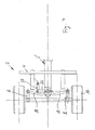
- Fig. 1 is a side view of a dolly axis 2 can be seen.
- the dolly axle 2 has a frame 4, a drawbar 6, a fifth wheel 8, a steerable wheelset 12 and a non-steerable wheelset 10.
- the drawbar 6 is formed in two parts and has a front drawbar part 6.1 and a rear, connected to the frame 4 drawbar part 6.2.
- the drawbar 6 can be attached with its front end to a trailer hitch of a towing vehicle.
- the shape of the drawbar is not limited to the embodiment shown in the example, but may also have other shapes, such as a gooseneck drawbar.
- a semi-trailer can be firmly connected to the fifth wheel 8. In this way it is possible to realize a team or a vehicle combination whose total length can be up to 25 meters.
- the corresponding truck can have additional cargo space, which is arranged for example on the towing vehicle.
- the drawbar is pivotable about a pivot axis 14, as is closer Fig. 2 evident.
- the Dolly axle 2 can be seen from a top view, in a position in which the drawbar for straight ahead driving 6 is in its neutral position with its front part 6.1 and its rear part 6.2. Due to the two-part drawbar the simple possibility is created to equip the vehicle for both low and normal dome heights.
- the fifth wheel 8 is arranged approximately centrally between the steerable wheelset 12 and the non-steerable wheelset 10.
- the dolly axle 2 is thus shown as a two-axle version, but can also be equipped and used as one-axle or more than two axles.
- the steering levers 16 can be seen on which attack in detail not shown transmission means. These are spaced from the axis of rotation of the steering joint arranged to use a lever travel for the adjustment of the steering angle can.
- the transmission means consist in the example of a shift link 18 and a tie rod 18.
- a corresponding shift link 18 is provided which engages articulated at 20 to the drawbar 6.
- the control arms 18 are preceded by two dampers 22, the articulated on the one hand on the frame 4 and on the other hand hinged to the drawbar 6.
- each end stop 24 is provided on the frame 4. These steering bar stops 24 prevent excessive steering of a vehicle combination. These can also be equipped so that when a stop of the drawbar 6 on the stop 24, an optical or acoustic signal is generated for a corresponding driver information.
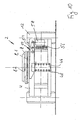
- Fig. 3 is a maximum trailing drawbar 6 with otherwise analogous structure as in the example Fig. 2 illustrated.
- the drawbar 6 is located at the top stop 24 in the drawing. In the example shown this corresponds to a drawbar maximum angle of 33 °.
- the drawbar is moved against the attacking damper 22, so that the in Fig. 3 upper damper 22 is retracted and in the Fig. 3 lower damper 22 is extended.
- These corresponding damping positions are in the Fig. 6 . 7 and 8th illustrates what needs to be discussed.
- arranged on the frame 4 saddle crest 8 has a rotatable fifth wheel plate 8.1, which cooperates with rotation stops 8.2. These act as end stops and minimize the friction between the fifth wheel and a semi-trailer. As a result, a lurching and rocking of the vehicle combination is prevented.
- the Fifthkupplungsendanelle 8.2 the coupling process can be done without manual intervention, since the possible angle of rotation is chosen so that the coupling of semi-trailer with the dolly axle centering the fifth wheel without manual intervention by the driver, for example by setting the fifth wheel, usually provided kingpin leads correctly and thus a secure and correct connection can be made.
- Fig. 4 and 5 is a detail of an embodiment of the invention shown.
- corresponding dampers are not shown, but can and should preferably be provided there.
- a steering geometry with a steering angle correction is shown here.
- the shift lever 18 and the tie rod 18 is pivotally connected to an adjusting lever 26, which in turn is pivotally connected at 26.1 with the drawbar 6 and articulated at 28.1 with a steering correction lever 28, which in turn is articulated to the frame 4.
- the articulation points 26.1 and 28.1 can be designed to be adjustable.
- the neutral position of the drawbar 6 is shown, whereas in Fig. 5 the drawbar is located on the upper stop 24 and is in its maximum pivoted position.
- the drawbar is located on the upper stop 24 and is in its maximum pivoted position.
- the adjustment lever is adjustable by a dimension S of about 80 mm, whereby an integrated steering angle correction of +/- 2 ° is possible to adjust the steering angle of the inside and outside steering angle to the radius of cornering.
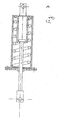
- Fig. 6 shows the pulled out by the drawbar movement damper. This corresponds to the position of in Fig. 3 lower damper 22.
- the Damper 22 has bearings 28 and 30 and a threaded rod 32 with a nut 34.
- a driver cup 36 is provided which can be loaded by a spring 38, which in turn is supported in the bent ends of the driver cup 36 at one end.
- This driver cup with the spring 38 is guided in the housing 40 of the damper.
- the threaded rod passes through a drive plate 42, at the other end, the spring 38 is supported.
- the drive plate 42 in turn is supported on the bent ends of the driver cup 36, at the inside also the head end 44 of the threaded rod 32 is supported.
- the damper builds up a force which counteracts the direction of movement of the drawbar 6.
- the damper 22 is in neutral position, as in Fig. 7 illustrated, the driver cup 36 is supported on the inner right wall of the housing 40.
- the spring is relaxed, so that the bearings 28 and 30 are unloaded.
- Fig. 8 the threaded rod is inserted. This corresponds to the in Fig. 3 upper damper 22 in the pivoted Switzerland Switzerlandichsellage.
- a draw block 46 is provided, the one above the other in pairs assignment holes 48 for connection of the drawbar - not shown - has at different altitudes.
- This drawbar 46 is further part of a reverse lock, which is generally numbered 50.
- This reverse lock 50 has a pivotable rinse aidsperrklaue 52 which is mounted at 54 and loaded by a spring 56.
- a pneumatic cylinder 58 this is in the in Fig.
Abstract
Description
Die Erfindung betrifft eine Dolly-Achse mit einer an einem Rahmen um eine vertikale Achse drehbeweglich befestigten Zugdeichsel und einer auf der Oberseite des Rahmens angeordneten Sattelkuppel sowie zumindest einem Radsatz, der von die Schwenkbewegung der Zugdeichsel übertragenen Übertragungsmitteln lenkbar ist, wobei vorzugsweise als Übertragungsmittel zumindest ein Schaltlenker vorgesehen ist, mit dem die Schwenkbewegung der Zugdeichsel auf wenigstens einen auf den lenkbaren Radsatz wirkenden Lenkhebel übertragbar ist und insbesondere die Lage des Schaltlenkers durch angetriebene Stellmittel veränderbar ist.The invention relates to a dolly axle with a drawbar rotatably mounted on a frame about a vertical axis and a saddle dome arranged on the upper side of the frame and at least one wheelset which is steerable by the pivoting movement of the drawbar transmission means, preferably at least one as transmission means Steering arm is provided, with which the pivoting movement of the drawbar is transferable to at least one steering lever acting on the steerable wheelset and in particular the position of the shift control arm is variable by driven adjusting means.
Eine derartige Dolly-Achse ist aus der
Das Dokument
Anstelle von aufwändigen und defektanfälligen Sensoren, motorischen Antrieben und Getriebe können bei dieser vorbekannten Dolly-Achse einfache mechanische Komponenten eingesetzt werden, wobei durch die Schwenkbewegung der Zugdeichsel ein Lenkwinkel vorgegeben ist, der von den Schaltlenkern entsprechend auf den lenkbaren Radsatz übertragen wird. Durch die Übertragung der Lenkbewegung der Zugdeichsel auf einen lenkbaren Radsatz kann der auf der Dolly-Achse aufliegende Anhänger in einem günstigen, von den Lenkbewegungen beeinflußten Radius um eine von der Zugmaschine gefahrene Kurve herumbewegt werden. Durch die Lenkung der Dolly-Achse sind insgesamt kleinere Wenderadien ermöglicht.Instead of consuming and fault-prone sensors, motor drives and gearbox simple mechanical components can be used in this known dolly axle, wherein the pivoting movement of the drawbar, a steering angle is set, according to the control of the toggle the steerable wheelset is transmitted. By transferring the steering movement of the drawbar to a steerable wheelset, the trailer resting on the dolly axle can be moved about a radius driven by the steering movements about a corner driven by the tractor. Due to the steering of the dolly axle altogether smaller turning radii are possible.
Durch eine Veränderung der Lage des Schaltlenkers wird die Geometrie der Übertragungsmittel verändert. Bei Lenkbewegungen ergeben sich in unterschiedlichen Stellpositionen des Schaltlenkers unterschiedlich starke Lenkbewegungen bei gleichem Einschlagwinkel der Zugdeichsel. In einer Schaltposition des Schaltlenkers können also beispielsweise bei niedrigen Rangiergeschwindigkeiten von der Zugdeichsel geringere Lenkbewegungen auf einen lenkbaren Radsatz übertragen werden, während in einer anderen Schaltposition des Schaltlenkers bei beispielsweise höheren Geschwindigkeiten die von der Zugdeichsel übertragenen Stellwege bei gleichem Winkel der Zugdeichsel größer sind. Bei der vorbekannten Dolly-Achse ist es daher möglich, mit kostengünstigen Stellelementen geschwindigkeitsabhängig unterschiedlich starke Lenkimpulse auf einen lenkbaren Radsatz zu übertragen.By changing the position of the shift control arm, the geometry of the transmission means is changed. When steering movements arise in different positions of the shift handlebars different strong steering movements at the same steering angle of the drawbar. In a switching position of the control arm so less steering movements can be transferred to a steerable wheelset, for example, at low shunting speeds of the drawbar, while in another switching position of the control arm at, for example, higher speeds transmitted by the drawbar parking paths at the same angle of the drawbar are greater. In the known dolly axle, it is therefore possible to transfer with low-cost actuators speed-dependent different strong steering pulses on a steerable wheelset.
Bei allen Vorteilen dieser vorbekannten Dolly-Achse ist allerdings zu beobachten, daß insbesondere bei sehr langen Fahrzeugkombinationen noch Schlingerbewegungen und ein Aufschaukeln der Fahrzeugkombination zu beobachten ist. Hier setzt die vorliegende Erfindung an, der die Aufgabe zugrunde liegt, bei Beibehaltung der Vorteile der vorgenannten Dolly-Achse das Lenkverhalten noch weiter zu verbessern.With all the advantages of this known dolly axle, however, it can be observed that, in particular in the case of very long vehicle combinations, rolling movements and rocking of the vehicle combination can still be observed. This is where the present invention, which is based on the object to improve the steering behavior while maintaining the advantages of the aforementioned dolly axle even further.
Zur Lösung dieser Aufgabe zeichnet sich die Dolly-Achse der eingangs genannten Art durch die Merkmale des Anspruchs 1 aus.To solve this problem, the dolly-axis of the aforementioned type is characterized by the features of claim 1.
Dadurch ist bei der Dolly-Achse eine Lenkgeometrie realisiert, bei der eine Lenkwinkelkorrektur durchgeführt werden kann, und zwar bevorzugt in Zusammenwirken mit einem Lenkungsdämpfer und einer drehbaren Sattelkuppel, die im weiteren noch näher vorgestellt werden. Dabei wird der Lenkwinkel der innen- und außenliegenden Räder an die real vorhandenen Winkel der Kurven bzw. Kreisfahrt angepaßt. Damit geht ein geringerer Reifenverschleiß sowie eine Rollwiderstandsminimierung einher. Dazu ist der Verstellhebel vorgesehen, an dem die Lenkhebel gelenkig angreifen, die ihrerseits gelenkig mit dem Schaltlenker verbunden sind. Aufgrund der dabei vorgesehenen Abstandsverhältnisse der Anlenkpunkte kann die entsprechende Lenkwinkelkorrektur durchgeführt werden. Dabei sind die Abstandsverhältnisse einstellbar und damit veränderbar.As a result, a steering geometry is implemented in the dolly axle, in which a steering angle correction can be carried out, preferably in cooperation with a steering damper and a rotatable saddle dome, which will be presented in more detail below. The steering angle of the inner and outer wheels is adapted to the actual existing angles of the curves or circular drive. This is accompanied by a lower tire wear and a rolling resistance minimization. For this purpose, the adjusting lever is provided, on which the steering levers attack articulated, which in turn are pivotally connected to the handlebar. Due to the distance ratios of the articulation points provided in this case, the corresponding steering angle correction can be performed. The distance ratios are adjustable and thus changeable.
In vorteilhafter Weise ist die Zugdeichsel über zumindest einen Dämpfer an dem Rahmen abstützbar. Damit ist eine Dolly-Achse zur Verfügung gestellt, bei der Schlingerbewegungen und auch ein Aufschaukeln der Fahrzeugkombination insgesamt wesentlich zu reduzieren sind. Der Dämpfer ist immer im Einsatz, so daß es auch bei unterschiedlichen Einschlagwinkeln der Zugdeichsel immer einen gedämpften Zustand der Zugdeichsel gibt. Vorzugsweise sind zwei Dämpfer vorgesehen, die jeweils in Fahrtrichtung rechts und links - bezogen auf die Mittelstellung der Zugdeichsel - an dieser einenends angreifen und sich anderenends am Rahmen abstützen.Advantageously, the drawbar is supported on at least one damper on the frame. Thus, a dolly axle is provided in which rolling movements and also a rocking of the vehicle combination are to be significantly reduced overall. The damper is always in use, so it Even with different steering angles of the drawbar is always a damped state of the drawbar. Preferably, two dampers are provided, each in the direction of travel right and left - based on the center position of the drawbar - attack on this one end and the other end are supported on the frame.
Bevorzugtermaßen ist der jeweilige Dämpfer ein Bauteil, das eine Gewindestange, einen Mitnehmertopf, ein Gehäuse sowie eine innenliegende Feder aufweist, wobei die Gewindestange relativ zum Mitnehmertopf und dem Gehäuse sowie der Mitnehmertopf relativ zu dem Gehäuse beweglich sind. Damit lassen sich verschiedene Stellungen für die Zugdeichsel einnehmen, nämlich einmal eine Mittelstellung, in der keine Kraft aufgebaut ist, und jeweilige Endstellungen mit eingeschobenem Mitnehmertopf und eingezogener Gewindestange und einer jeweils ausgezogenen Position der Gewindestange bei innenseitige Verlagerung des Mitnehmertopfes mitsamt der Feder und selbstverständlich entsprechende Zwischenstellungen. In der Neutralstellung, also der Mittelstellung der Zugdeichsel, ist das Lager der Gewindestange unbelastet, wobei es in den jeweiligen Endstellungen zu einer Belastung an der Gewindestange in den entsprechenden Lagerstellen kommt, die etwaigen Schlingerbewegungen entgegenwirkt.Preferred dimensions of the respective damper is a component having a threaded rod, a driver cup, a housing and an inner spring, wherein the threaded rod relative to the driver cup and the housing and the driver cup are movable relative to the housing. This can take various positions for the drawbar, namely once a middle position in which no force is built, and respective end positions with inserted driver cup and retracted threaded rod and a respective extended position of the threaded rod in the inside displacement of the driver cup together with the spring and of course corresponding intermediate positions , In the neutral position, ie the center position of the drawbar, the bearing of the threaded rod is unloaded, wherein it comes in the respective end positions to a load on the threaded rod in the corresponding bearing points, which counteracts any rolling movements.
Des weiteren ist bevorzugterweise die Sattelplatte hinsichtlich ihrer Drehbewegung bzw. hinsichtlich ihrer Rotation begrenzt. Die Sattelplatte bzw. die Sattelkuppel ist drehbar gelagert, damit durch eine Reibung zwischen Sattelkuppel und Sattelauflieger geringe Reibungskräfte anfallen. Größere auftretende Reibungskräfte würden ein Aufschaukeln der Fahrzeugkombination bewirken. Durch eine vorgesehene Spurstange bzw. Lenkstange ist der Kupplungsvorgang ohne manuelle Eingriffe möglich. Dabei ist die Verwendung von Standardachsen möglich. In Kombination mit dem Lenkungsdämpfer und der drehbaren Sattelkuppel ist ein Aufschaukeln wirksam verhindert. Durch die Dämpfer, die beidseits der Zugdeichsel angreifen, ist auch eine Rückstellung der Zugdeichsel in die Neutralstellung möglich. Vorteilhafterweise ist ebenfalls noch ein Endanschlag an dem Rahmen vorgesehen, um die maximale Auslenkung der Zugdeichsel zu begrenzen.Furthermore, the fifth wheel plate is preferably limited in terms of its rotational movement or with respect to its rotation. The saddle plate or the saddle dome is rotatably mounted so that caused by friction between saddle dome and semi-trailer low frictional forces. Larger occurring friction forces would cause a rocking of the vehicle combination. By an intended tie rod or handlebar the coupling process without manual intervention is possible. The use of standard axes is possible. In combination with the steering damper and the rotatable saddle dome swaying is effectively prevented. By the dampers, which attack both sides of the drawbar, a provision of the drawbar in the neutral position is possible. Advantageously, an end stop is also provided on the frame in order to limit the maximum deflection of the drawbar.
Bevorzugterweise ist auch noch eine Rückfahrsperre vorgesehen, bei der über eine mit der Zugdeichsel verbindbare federbelastete Rückfahrsperrklaue die Zugdeichsel verriegelbar ist, und zwar in ihrer Neutralstellung. Diese Rückfahrsperre kann über einen Zylinder zu betätigen sein. Des weiteren kann vorgesehen sein, daß die Zugdeichsel höhenverstellbar mit dem Rahmen verbindbar ist, wozu eine Befestigungsanordnung mit übereinander angeordneten Befestigungslöchern vorgesehen ist.Preferably, a reverse lock is also provided, in which via a connectable to the drawbar spring-loaded Rückfahrsperrklaue the drawbar is locked, in its neutral position. This reverse lock can be operated via a cylinder. Furthermore, it can be provided that the drawbar is adjustable in height connected to the frame, including a mounting arrangement is provided with superposed mounting holes.
Weitere vorteilhafte Ausgestaltungen der Erfindung ergeben sich aus weiteren Unteransprüchen, der nachfolgenden Beschreibung und der Zeichnung. In der Zeichnung zeigen:
- Fig. 1
- Seitenansicht einer Dolly-Achse,
- Fig. 2
- eine Draufsicht auf das Beispiel nach
Fig. 1 in der Neutralstellung der Zugdeichsel, - Fig. 3
- eine Ansicht von oben auf das Beispiel nach
Fig. 1 mit eingeschlagener Zugdeichsel; - Fig. 4
- einen Ausschnitt der Darstellung nach
Fig. 2 ohne Darstellung von Dämpferelementen, aber mit Darstellung einer erfindungsgemäßen Lenkwinkelkorrektur, - Fig. 5
- eine zu
Fig. 4 analoge Darstellung mit eingeschlagener Zugdeichsel, - Fig. 6
- in einer teilweise geschnittenen Querschnittsdarstellung ein Ausführungsbeispiel eines Dämpferelementes im ausgezogenen Zustand,
- Fig. 7
- das Ausführungsbeispiel nach
Fig. 6 in Neutralstellung der Zugdeichsel, - Fig. 8
- das Ausführungsbeispiel nach den
Fig. 6 und7 im eingeschobenen Zustand des Dämpfers, - Fig. 9
- eine Ansicht von vorne auf die Dolly-Achse mit eingerasteter Rückfahrsperrklaue, und
- Fig. 10
- eine zu
Fig. 9 analoge Darstellung mit entriegelter Rückfahrsperrklaue.
- Fig. 1
- Side view of a dolly axle,
- Fig. 2
- a plan view of the example
Fig. 1 in the neutral position of the drawbar, - Fig. 3
- a top view of the example
Fig. 1 with drawbar turned on; - Fig. 4
- a section of the representation after
Fig. 2 without representation of damper elements, but with representation of a steering angle correction according to the invention, - Fig. 5
- one too
Fig. 4 analogue representation with turned drawbar, - Fig. 6
- in a partially sectioned cross-sectional view of an embodiment of a damper element in the extended state,
- Fig. 7
- the embodiment according to
Fig. 6 in the neutral position of the drawbar, - Fig. 8
- the embodiment of the
Fig. 6 and7 in the inserted state of the damper, - Fig. 9
- a view from the front on the dolly axle with latched Rückfahrsperrklaue, and
- Fig. 10
- one too
Fig. 9 analogue representation with unlocked reversing pawl.
In der Zeichnung sind grundsätzlich gleichwirkende Teile mit übereinstimmenden Bezugsziffern bezeichnet.In the drawing, basically equivalent parts are designated by matching reference numerals.
In
Die Zugdeichsel ist um eine Schwenkachse 14 schwenkbar, wie dies näher aus
Die Sattelkupplung 8 ist etwa mittig zwischen dem lenkbaren Radsatz 12 und dem nicht lenkbaren Radsatz 10 angeordnet. Im Beispiel ist die Dolly-Achse 2 also als Zweiachsausführung gezeigt, kann aber auch als Einachs- oder mehr als zwei Achsen entsprechend ausgerüstet und eingesetzt werden.The
In den
In
Wie ebenfalls aus den
In
In den
In den
Claims (22)
- Dolly axle (2) having a tow bar (6) which is fastened to a frame (4) to be movable in rotation about a vertical axis (14) and having a fifth wheel coupling (8) which is arranged on the upper side of the frame (4) and also having at least one wheel set (12) which is steerable by transmitting means which transmit the pivoting movement of the tow bar (6), what are provided as transmitting means being variable-position links (18) by which the pivoting movement of the tow bar (6) can be transmitted to respective ones of steering arms (16) acting on the steerable wheel set (12), there engaging, via a joint, with a respective steering arm (16) associated with a steerable wheel set (12), a variable-position link (18) which is connected, by a joint, to an adjusting lever (26), which in turn can be adjusted by means of a steering correcting arm (28) to match the steering angle of the wheels of the steerable wheel set (12) which are situated on the inside and outside to the actual angle of bends or turns or circles which are driven through.
- Dolly axle according to claim 1, characterised in that the adjusting lever (26) can be fastened to the tow bar (6), to be movable by pivoting, in such a way that its position can be changed.
- Dolly axle according to claim 1 or claim 2, characterised in that the adjusting lever (26) and the steering correcting arm (28) are fastened to one another in such way that their positions can be changed.
- Dolly axle according to one of claims 1 to 3, characterised in that the tow bar (6) can be supported on the frame (4) via at least one damper (22).
- Dolly axle according to one of claims 1 to 4, characterised in that two dampers (22) engage with the tow bar (6).
- Dolly axle according to one of claims 1 to 5, characterised in that the dampers (22) are co-axially aligned.
- Dolly axle according to one of claims 1 to 6, characterised in that a hydraulically or pneumatically acting damping member is provided as a damper (22).
- Dolly axle according to one of claims 1 to 7, characterised in that the damper (22) has a spring-loaded entraining cup (36) in which an entraining member able to be connected to the tow bar (6) engages.
- Dolly axle according to claim 8, characterised in that the entraining member is in the form of a rod.
- Dolly axle according to claim 9, characterised in that the entraining member is in the form of a threaded rod (32).
- Dolly axle according to one of claims 1 to 10, characterised in that the damper (22) has an entraining disc (44) which can be supported at one end against the cover (40.1) of the damper.
- Dolly axle according to one of claims 1 to 11, characterised in that the damper (22) has a body (40) against which, on the inside, an entraining cup (36) able to be moved relative to the said body (40) and an entraining member which is able to be moved relative to the said entraining cup (36) and which can be fastened to the tow bar (6) can be supported.
- Dolly axle according to one of claims 1 to 12, characterised in that the fifth wheel coupling (8) arranged on the frame (4) has a top plate (8.1), having built-in stops for rotation (8.2), which is mounted to be rotatable.
- Dolly axle according to one of claims 1 to 13, characterised in that the tow bar (6) is in at least two parts and the dampers (22) engage with that part (6.2) of the tow bar (6) which is at the frame end.
- Dolly axle according to one of claims 1 to 14, characterised in that tow bar stops (24) are provided for the tow bar (6).
- Dolly axle according to claim 15, characterised in that the tow bar stops (24) are fastened to the frame (4).
- Dolly axle according to one of claims 1 to 16, characterised in that a lock for reversing (50) is provided.
- Dolly axle according to claim 17, characterised in that the lock for reversing (56) has a spring loading locking claw (52) for reversing which can be connected to the tow bar (6) and which can be locked to and unlocked from the tow bar (6).
- Dolly axle according to claim 17 or 18, characterised in that the lock for reversing (50) can be actuated by means of a cylinder (58).
- Dolly axle according to claim 19, characterised in that the cylinder (58) takes the form of a single-acting pneumatic cylinder.
- Dolly axle according to one of claims 1 to 20, characterised in that the tow bar (6) can be connected to the frame in such a way that it can be adjusted in the heightwise direction.
- Dolly axle according to claim 21, characterised in that the tow bar (6) can be fastened to a tow bar plate (46) having holes (48) provided at different heights.
Priority Applications (1)
| Application Number | Priority Date | Filing Date | Title |
|---|---|---|---|
| PL07011529T PL1900610T3 (en) | 2006-09-15 | 2007-06-13 | Dolly axle |
Applications Claiming Priority (1)
| Application Number | Priority Date | Filing Date | Title |
|---|---|---|---|
| DE102006044202A DE102006044202A1 (en) | 2006-09-15 | 2006-09-15 | Dolly axle |
Publications (3)
| Publication Number | Publication Date |
|---|---|
| EP1900610A2 EP1900610A2 (en) | 2008-03-19 |
| EP1900610A3 EP1900610A3 (en) | 2008-08-06 |
| EP1900610B1 true EP1900610B1 (en) | 2010-02-10 |
Family
ID=38657129
Family Applications (1)
| Application Number | Title | Priority Date | Filing Date |
|---|---|---|---|
| EP07011529A Active EP1900610B1 (en) | 2006-09-15 | 2007-06-13 | Dolly axle |
Country Status (6)
| Country | Link |
|---|---|
| EP (1) | EP1900610B1 (en) |
| AT (1) | ATE457257T1 (en) |
| DE (2) | DE102006044202A1 (en) |
| DK (1) | DK1900610T3 (en) |
| ES (1) | ES2340423T3 (en) |
| PL (1) | PL1900610T3 (en) |
Cited By (6)
| Publication number | Priority date | Publication date | Assignee | Title |
|---|---|---|---|---|
| US10670479B2 (en) | 2018-02-27 | 2020-06-02 | Methode Electronics, Inc. | Towing systems and methods using magnetic field sensing |
| US10696109B2 (en) | 2017-03-22 | 2020-06-30 | Methode Electronics Malta Ltd. | Magnetolastic based sensor assembly |
| US11084342B2 (en) | 2018-02-27 | 2021-08-10 | Methode Electronics, Inc. | Towing systems and methods using magnetic field sensing |
| US11135882B2 (en) | 2018-02-27 | 2021-10-05 | Methode Electronics, Inc. | Towing systems and methods using magnetic field sensing |
| US11221262B2 (en) | 2018-02-27 | 2022-01-11 | Methode Electronics, Inc. | Towing systems and methods using magnetic field sensing |
| US11491832B2 (en) | 2018-02-27 | 2022-11-08 | Methode Electronics, Inc. | Towing systems and methods using magnetic field sensing |
Families Citing this family (4)
| Publication number | Priority date | Publication date | Assignee | Title |
|---|---|---|---|---|
| EP2634018B1 (en) | 2012-02-29 | 2014-11-26 | Helmut Fliegl | Dolly axle |
| FR3046803B1 (en) * | 2016-01-19 | 2018-01-19 | Benedetti-Guelpa | SNOW TRAILER |
| EP3398842B1 (en) | 2017-05-04 | 2020-10-28 | Helmut Fliegl | Dolly for semitrailers |
| DE102020115469B4 (en) | 2020-06-10 | 2022-04-21 | Sommer Gmbh | Dolly trailer, train with such a dolly trailer and method for operating such a train |
Family Cites Families (10)
| Publication number | Priority date | Publication date | Assignee | Title |
|---|---|---|---|---|
| DE646443C (en) * | 1936-04-02 | 1937-06-17 | Hans Schroeter | Damping device connected to the trailer steering device for the slinging or rolling movements on trailers |
| GB843023A (en) * | 1957-09-17 | 1960-08-04 | Davies Magnet Works Ltd | Improvements in or relating to trailer fifth wheel couplings |
| CH415310A (en) * | 1965-05-06 | 1966-06-15 | Moser Werner | Steering on train cars and trailers |
| US4281847A (en) * | 1979-08-22 | 1981-08-04 | The University Of Kentucky Research Foundation | Trailer hitch |
| GB8523047D0 (en) * | 1985-09-18 | 1985-10-23 | Econ Group Ltd | Trailer draw-bar control |
| US6158759A (en) * | 1998-11-02 | 2000-12-12 | Perry; Duane L. | Wagon steering control mechanism |
| DE19905676B4 (en) * | 1999-02-11 | 2005-07-07 | Bpw Bergische Achsen Kg | Drawbar for central axle trailer |
| DE50313254D1 (en) * | 2002-05-10 | 2010-12-23 | Zeiss Carl Smt Ag | REFLECTIVE ROENTGENIC MICROSCOPE FOR EXAMINATION OF OBJECTS WITH WAVELENGTH = 100NM IN REFLECTION |
| DE20305794U1 (en) * | 2003-04-10 | 2003-07-10 | Fahrzeugwerk Bernard Krone | Dolly axle with steerable wheelset |
| SE522796C2 (en) * | 2003-05-08 | 2004-03-09 | Scania Cv Abp | Steerable vehicle unit involves steering stay system working in conjunction with draw bar for pivoting wheel on front wheel axis |
-
2006
- 2006-09-15 DE DE102006044202A patent/DE102006044202A1/en not_active Ceased
-
2007
- 2007-06-13 DE DE502007002799T patent/DE502007002799D1/en active Active
- 2007-06-13 EP EP07011529A patent/EP1900610B1/en active Active
- 2007-06-13 PL PL07011529T patent/PL1900610T3/en unknown
- 2007-06-13 AT AT07011529T patent/ATE457257T1/en active
- 2007-06-13 ES ES07011529T patent/ES2340423T3/en active Active
- 2007-06-13 DK DK07011529.0T patent/DK1900610T3/en active
Cited By (7)
| Publication number | Priority date | Publication date | Assignee | Title |
|---|---|---|---|---|
| US10696109B2 (en) | 2017-03-22 | 2020-06-30 | Methode Electronics Malta Ltd. | Magnetolastic based sensor assembly |
| US10940726B2 (en) | 2017-03-22 | 2021-03-09 | Methode Electronics Malta Ltd. | Magnetoelastic based sensor assembly |
| US10670479B2 (en) | 2018-02-27 | 2020-06-02 | Methode Electronics, Inc. | Towing systems and methods using magnetic field sensing |
| US11084342B2 (en) | 2018-02-27 | 2021-08-10 | Methode Electronics, Inc. | Towing systems and methods using magnetic field sensing |
| US11135882B2 (en) | 2018-02-27 | 2021-10-05 | Methode Electronics, Inc. | Towing systems and methods using magnetic field sensing |
| US11221262B2 (en) | 2018-02-27 | 2022-01-11 | Methode Electronics, Inc. | Towing systems and methods using magnetic field sensing |
| US11491832B2 (en) | 2018-02-27 | 2022-11-08 | Methode Electronics, Inc. | Towing systems and methods using magnetic field sensing |
Also Published As
| Publication number | Publication date |
|---|---|
| DE102006044202A1 (en) | 2008-05-21 |
| ATE457257T1 (en) | 2010-02-15 |
| PL1900610T3 (en) | 2010-07-30 |
| DE502007002799D1 (en) | 2010-03-25 |
| EP1900610A2 (en) | 2008-03-19 |
| EP1900610A3 (en) | 2008-08-06 |
| DK1900610T3 (en) | 2010-06-07 |
| ES2340423T3 (en) | 2010-06-02 |
Similar Documents
| Publication | Publication Date | Title |
|---|---|---|
| EP1900610B1 (en) | Dolly axle | |
| EP1900609A2 (en) | Dolly axle | |
| EP0544727B1 (en) | Vehicle | |
| EP1900618B1 (en) | Dolly axle | |
| DE3031862C2 (en) | Articulated vehicle with several axles | |
| EP1466813B1 (en) | Dolly axle with steerable wheelset | |
| DE2844626A1 (en) | MECHANICAL TRACKABLE ROAD-ACCESSIBLE VEHICLE | |
| EP2069188B1 (en) | Device for swivel joint coupling, particularly for semi-trailers | |
| EP1900612A2 (en) | Dolly axle | |
| EP1900611A2 (en) | Dolly axle | |
| EP3398842B1 (en) | Dolly for semitrailers | |
| DE3002354C2 (en) | Pulling and steering device for a truck trailer | |
| DE3402442A1 (en) | Lorry | |
| EP2239188B9 (en) | Goose-neck for a vehicle, especially for a heavy duty vehicle | |
| DE3145871A1 (en) | Trailer coupling device of a lorry | |
| DE102008063660B4 (en) | Dolly for a tractor trailer | |
| DE2263506A1 (en) | CONTROL DEVICE FOR A TRAILED CAR | |
| DE102016102318A1 (en) | Load-bearing four-wheeled trailer for a towing train | |
| DE3328123A1 (en) | Road train with a steering facility for the trailer vehicle | |
| EP0388363B1 (en) | Trailerhitch for vehicles | |
| DE3004885A1 (en) | TRAILER FOR TRUCKS | |
| EP2181032A1 (en) | Steering arrangement for vehicles | |
| DE10346299A1 (en) | Mechanical positively steered axle for central axle trailer has hydraulic cylinder combination with pressure accumulator fitted in steering gear, and acts as overload protection | |
| DE102016113800B4 (en) | vehicle trailer | |
| DE10158868B4 (en) | Self-steering vehicle trailer |
Legal Events
| Date | Code | Title | Description |
|---|---|---|---|
| PUAI | Public reference made under article 153(3) epc to a published international application that has entered the european phase |
Free format text: ORIGINAL CODE: 0009012 |
|
| AK | Designated contracting states |
Kind code of ref document: A2 Designated state(s): AT BE BG CH CY CZ DE DK EE ES FI FR GB GR HU IE IS IT LI LT LU LV MC MT NL PL PT RO SE SI SK TR |
|
| AX | Request for extension of the european patent |
Extension state: AL BA HR MK YU |
|
| PUAL | Search report despatched |
Free format text: ORIGINAL CODE: 0009013 |
|
| AK | Designated contracting states |
Kind code of ref document: A3 Designated state(s): AT BE BG CH CY CZ DE DK EE ES FI FR GB GR HU IE IS IT LI LT LU LV MC MT NL PL PT RO SE SI SK TR |
|
| AX | Request for extension of the european patent |
Extension state: AL BA HR MK RS |
|
| 17P | Request for examination filed |
Effective date: 20080918 |
|
| 17Q | First examination report despatched |
Effective date: 20081017 |
|
| R17P | Request for examination filed (corrected) |
Effective date: 20080918 |
|
| AKX | Designation fees paid |
Designated state(s): AT BE BG CH CY CZ DE DK EE ES FI FR GB GR HU IE IS IT LI LT LU LV MC MT NL PL PT RO SE SI SK TR |
|
| GRAP | Despatch of communication of intention to grant a patent |
Free format text: ORIGINAL CODE: EPIDOSNIGR1 |
|
| GRAS | Grant fee paid |
Free format text: ORIGINAL CODE: EPIDOSNIGR3 |
|
| GRAA | (expected) grant |
Free format text: ORIGINAL CODE: 0009210 |
|
| AK | Designated contracting states |
Kind code of ref document: B1 Designated state(s): AT BE BG CH CY CZ DE DK EE ES FI FR GB GR HU IE IS IT LI LT LU LV MC MT NL PL PT RO SE SI SK TR |
|
| REG | Reference to a national code |
Ref country code: GB Ref legal event code: FG4D Free format text: NOT ENGLISH |
|
| REG | Reference to a national code |
Ref country code: CH Ref legal event code: EP |
|
| REG | Reference to a national code |
Ref country code: IE Ref legal event code: FG4D |
|
| REF | Corresponds to: |
Ref document number: 502007002799 Country of ref document: DE Date of ref document: 20100325 Kind code of ref document: P |
|
| REG | Reference to a national code |
Ref country code: NL Ref legal event code: T3 |
|
| REG | Reference to a national code |
Ref country code: SE Ref legal event code: TRGR |
|
| REG | Reference to a national code |
Ref country code: ES Ref legal event code: FG2A Ref document number: 2340423 Country of ref document: ES Kind code of ref document: T3 |
|
| REG | Reference to a national code |
Ref country code: DK Ref legal event code: T3 |
|
| LTIE | Lt: invalidation of european patent or patent extension |
Effective date: 20100210 |
|
| PG25 | Lapsed in a contracting state [announced via postgrant information from national office to epo] |
Ref country code: PT Free format text: LAPSE BECAUSE OF FAILURE TO SUBMIT A TRANSLATION OF THE DESCRIPTION OR TO PAY THE FEE WITHIN THE PRESCRIBED TIME-LIMIT Effective date: 20100611 Ref country code: IS Free format text: LAPSE BECAUSE OF FAILURE TO SUBMIT A TRANSLATION OF THE DESCRIPTION OR TO PAY THE FEE WITHIN THE PRESCRIBED TIME-LIMIT Effective date: 20100610 Ref country code: LT Free format text: LAPSE BECAUSE OF FAILURE TO SUBMIT A TRANSLATION OF THE DESCRIPTION OR TO PAY THE FEE WITHIN THE PRESCRIBED TIME-LIMIT Effective date: 20100210 |
|
| REG | Reference to a national code |
Ref country code: PL Ref legal event code: T3 |
|
| PG25 | Lapsed in a contracting state [announced via postgrant information from national office to epo] |
Ref country code: FI Free format text: LAPSE BECAUSE OF FAILURE TO SUBMIT A TRANSLATION OF THE DESCRIPTION OR TO PAY THE FEE WITHIN THE PRESCRIBED TIME-LIMIT Effective date: 20100210 Ref country code: LV Free format text: LAPSE BECAUSE OF FAILURE TO SUBMIT A TRANSLATION OF THE DESCRIPTION OR TO PAY THE FEE WITHIN THE PRESCRIBED TIME-LIMIT Effective date: 20100210 Ref country code: SI Free format text: LAPSE BECAUSE OF FAILURE TO SUBMIT A TRANSLATION OF THE DESCRIPTION OR TO PAY THE FEE WITHIN THE PRESCRIBED TIME-LIMIT Effective date: 20100210 |
|
| REG | Reference to a national code |
Ref country code: IE Ref legal event code: FD4D |
|
| PG25 | Lapsed in a contracting state [announced via postgrant information from national office to epo] |
Ref country code: GR Free format text: LAPSE BECAUSE OF FAILURE TO SUBMIT A TRANSLATION OF THE DESCRIPTION OR TO PAY THE FEE WITHIN THE PRESCRIBED TIME-LIMIT Effective date: 20100511 Ref country code: CY Free format text: LAPSE BECAUSE OF FAILURE TO SUBMIT A TRANSLATION OF THE DESCRIPTION OR TO PAY THE FEE WITHIN THE PRESCRIBED TIME-LIMIT Effective date: 20100210 Ref country code: EE Free format text: LAPSE BECAUSE OF FAILURE TO SUBMIT A TRANSLATION OF THE DESCRIPTION OR TO PAY THE FEE WITHIN THE PRESCRIBED TIME-LIMIT Effective date: 20100210 Ref country code: RO Free format text: LAPSE BECAUSE OF FAILURE TO SUBMIT A TRANSLATION OF THE DESCRIPTION OR TO PAY THE FEE WITHIN THE PRESCRIBED TIME-LIMIT Effective date: 20100210 Ref country code: IE Free format text: LAPSE BECAUSE OF FAILURE TO SUBMIT A TRANSLATION OF THE DESCRIPTION OR TO PAY THE FEE WITHIN THE PRESCRIBED TIME-LIMIT Effective date: 20100210 |
|
| PG25 | Lapsed in a contracting state [announced via postgrant information from national office to epo] |
Ref country code: CZ Free format text: LAPSE BECAUSE OF FAILURE TO SUBMIT A TRANSLATION OF THE DESCRIPTION OR TO PAY THE FEE WITHIN THE PRESCRIBED TIME-LIMIT Effective date: 20100210 Ref country code: SK Free format text: LAPSE BECAUSE OF FAILURE TO SUBMIT A TRANSLATION OF THE DESCRIPTION OR TO PAY THE FEE WITHIN THE PRESCRIBED TIME-LIMIT Effective date: 20100210 Ref country code: BG Free format text: LAPSE BECAUSE OF FAILURE TO SUBMIT A TRANSLATION OF THE DESCRIPTION OR TO PAY THE FEE WITHIN THE PRESCRIBED TIME-LIMIT Effective date: 20100510 |
|
| PLBE | No opposition filed within time limit |
Free format text: ORIGINAL CODE: 0009261 |
|
| STAA | Information on the status of an ep patent application or granted ep patent |
Free format text: STATUS: NO OPPOSITION FILED WITHIN TIME LIMIT |
|
| 26N | No opposition filed |
Effective date: 20101111 |
|
| PG25 | Lapsed in a contracting state [announced via postgrant information from national office to epo] |
Ref country code: MC Free format text: LAPSE BECAUSE OF NON-PAYMENT OF DUE FEES Effective date: 20100630 |
|
| PG25 | Lapsed in a contracting state [announced via postgrant information from national office to epo] |
Ref country code: IT Free format text: LAPSE BECAUSE OF NON-PAYMENT OF DUE FEES Effective date: 20100613 |
|
| PG25 | Lapsed in a contracting state [announced via postgrant information from national office to epo] |
Ref country code: MT Free format text: LAPSE BECAUSE OF FAILURE TO SUBMIT A TRANSLATION OF THE DESCRIPTION OR TO PAY THE FEE WITHIN THE PRESCRIBED TIME-LIMIT Effective date: 20100210 |
|
| REG | Reference to a national code |
Ref country code: CH Ref legal event code: PL |
|
| PG25 | Lapsed in a contracting state [announced via postgrant information from national office to epo] |
Ref country code: LI Free format text: LAPSE BECAUSE OF NON-PAYMENT OF DUE FEES Effective date: 20110630 Ref country code: CH Free format text: LAPSE BECAUSE OF NON-PAYMENT OF DUE FEES Effective date: 20110630 |
|
| PG25 | Lapsed in a contracting state [announced via postgrant information from national office to epo] |
Ref country code: LU Free format text: LAPSE BECAUSE OF NON-PAYMENT OF DUE FEES Effective date: 20100613 Ref country code: HU Free format text: LAPSE BECAUSE OF FAILURE TO SUBMIT A TRANSLATION OF THE DESCRIPTION OR TO PAY THE FEE WITHIN THE PRESCRIBED TIME-LIMIT Effective date: 20100811 |
|
| REG | Reference to a national code |
Ref country code: FR Ref legal event code: PLFP Year of fee payment: 10 |
|
| REG | Reference to a national code |
Ref country code: FR Ref legal event code: PLFP Year of fee payment: 11 |
|
| REG | Reference to a national code |
Ref country code: FR Ref legal event code: PLFP Year of fee payment: 12 |
|
| PGFP | Annual fee paid to national office [announced via postgrant information from national office to epo] |
Ref country code: DK Payment date: 20190515 Year of fee payment: 13 Ref country code: NL Payment date: 20190626 Year of fee payment: 13 Ref country code: IT Payment date: 20190604 Year of fee payment: 13 Ref country code: PL Payment date: 20190506 Year of fee payment: 13 |
|
| PGFP | Annual fee paid to national office [announced via postgrant information from national office to epo] |
Ref country code: TR Payment date: 20190429 Year of fee payment: 13 Ref country code: SE Payment date: 20190617 Year of fee payment: 13 Ref country code: FR Payment date: 20190625 Year of fee payment: 13 Ref country code: BE Payment date: 20190426 Year of fee payment: 13 |
|
| PGFP | Annual fee paid to national office [announced via postgrant information from national office to epo] |
Ref country code: ES Payment date: 20190703 Year of fee payment: 13 Ref country code: AT Payment date: 20190612 Year of fee payment: 13 Ref country code: GB Payment date: 20190410 Year of fee payment: 13 |
|
| REG | Reference to a national code |
Ref country code: DK Ref legal event code: EBP Effective date: 20200630 |
|
| REG | Reference to a national code |
Ref country code: NL Ref legal event code: MM Effective date: 20200701 |
|
| REG | Reference to a national code |
Ref country code: AT Ref legal event code: MM01 Ref document number: 457257 Country of ref document: AT Kind code of ref document: T Effective date: 20200613 |
|
| GBPC | Gb: european patent ceased through non-payment of renewal fee |
Effective date: 20200613 |
|
| REG | Reference to a national code |
Ref country code: BE Ref legal event code: MM Effective date: 20200630 |
|
| PG25 | Lapsed in a contracting state [announced via postgrant information from national office to epo] |
Ref country code: GB Free format text: LAPSE BECAUSE OF NON-PAYMENT OF DUE FEES Effective date: 20200613 Ref country code: FR Free format text: LAPSE BECAUSE OF NON-PAYMENT OF DUE FEES Effective date: 20200630 Ref country code: NL Free format text: LAPSE BECAUSE OF NON-PAYMENT OF DUE FEES Effective date: 20200701 |
|
| PG25 | Lapsed in a contracting state [announced via postgrant information from national office to epo] |
Ref country code: AT Free format text: LAPSE BECAUSE OF NON-PAYMENT OF DUE FEES Effective date: 20200613 Ref country code: BE Free format text: LAPSE BECAUSE OF NON-PAYMENT OF DUE FEES Effective date: 20200630 Ref country code: SE Free format text: LAPSE BECAUSE OF NON-PAYMENT OF DUE FEES Effective date: 20200614 |
|
| PG25 | Lapsed in a contracting state [announced via postgrant information from national office to epo] |
Ref country code: DK Free format text: LAPSE BECAUSE OF NON-PAYMENT OF DUE FEES Effective date: 20200630 |
|
| REG | Reference to a national code |
Ref country code: SE Ref legal event code: EUG |
|
| REG | Reference to a national code |
Ref country code: ES Ref legal event code: FD2A Effective date: 20211102 |
|
| PG25 | Lapsed in a contracting state [announced via postgrant information from national office to epo] |
Ref country code: ES Free format text: LAPSE BECAUSE OF NON-PAYMENT OF DUE FEES Effective date: 20200614 |
|
| PG25 | Lapsed in a contracting state [announced via postgrant information from national office to epo] |
Ref country code: TR Free format text: LAPSE BECAUSE OF NON-PAYMENT OF DUE FEES Effective date: 20200613 |
|
| PG25 | Lapsed in a contracting state [announced via postgrant information from national office to epo] |
Ref country code: IT Free format text: LAPSE BECAUSE OF NON-PAYMENT OF DUE FEES Effective date: 20200613 |
|
| P01 | Opt-out of the competence of the unified patent court (upc) registered |
Effective date: 20230518 |
|
| PGFP | Annual fee paid to national office [announced via postgrant information from national office to epo] |
Ref country code: DE Payment date: 20230620 Year of fee payment: 17 |
|
| PG25 | Lapsed in a contracting state [announced via postgrant information from national office to epo] |
Ref country code: PL Free format text: LAPSE BECAUSE OF NON-PAYMENT OF DUE FEES Effective date: 20200613 |