EP1900459A2 - Linearer Schieberverschluss für ein metallurgisches Gefäß - Google Patents
Linearer Schieberverschluss für ein metallurgisches Gefäß Download PDFInfo
- Publication number
- EP1900459A2 EP1900459A2 EP07121932A EP07121932A EP1900459A2 EP 1900459 A2 EP1900459 A2 EP 1900459A2 EP 07121932 A EP07121932 A EP 07121932A EP 07121932 A EP07121932 A EP 07121932A EP 1900459 A2 EP1900459 A2 EP 1900459A2
- Authority
- EP
- European Patent Office
- Prior art keywords
- slide plate
- gate valve
- sliding gate
- clamping ring
- plate
- Prior art date
- Legal status (The legal status is an assumption and is not a legal conclusion. Google has not performed a legal analysis and makes no representation as to the accuracy of the status listed.)
- Granted
Links
- 230000009021 linear effect Effects 0.000 title claims abstract description 47
- 238000009826 distribution Methods 0.000 claims abstract description 5
- 230000000903 blocking effect Effects 0.000 claims description 31
- 229910000831 Steel Inorganic materials 0.000 claims description 24
- 239000010959 steel Substances 0.000 claims description 24
- CPLXHLVBOLITMK-UHFFFAOYSA-N Magnesium oxide Chemical compound [Mg]=O CPLXHLVBOLITMK-UHFFFAOYSA-N 0.000 claims description 4
- VYPSYNLAJGMNEJ-UHFFFAOYSA-N Silicium dioxide Chemical compound O=[Si]=O VYPSYNLAJGMNEJ-UHFFFAOYSA-N 0.000 claims description 4
- MCMNRKCIXSYSNV-UHFFFAOYSA-N Zirconium dioxide Chemical compound O=[Zr]=O MCMNRKCIXSYSNV-UHFFFAOYSA-N 0.000 claims description 4
- 238000003825 pressing Methods 0.000 claims description 3
- 239000000126 substance Substances 0.000 claims description 3
- OKTJSMMVPCPJKN-UHFFFAOYSA-N Carbon Chemical compound [C] OKTJSMMVPCPJKN-UHFFFAOYSA-N 0.000 claims description 2
- PNEYBMLMFCGWSK-UHFFFAOYSA-N aluminium oxide Inorganic materials [O-2].[O-2].[O-2].[Al+3].[Al+3] PNEYBMLMFCGWSK-UHFFFAOYSA-N 0.000 claims description 2
- 229910052799 carbon Inorganic materials 0.000 claims description 2
- 239000000395 magnesium oxide Substances 0.000 claims description 2
- 239000000377 silicon dioxide Substances 0.000 claims description 2
- 230000007246 mechanism Effects 0.000 description 72
- 230000009467 reduction Effects 0.000 description 24
- 230000008878 coupling Effects 0.000 description 22
- 238000010168 coupling process Methods 0.000 description 22
- 238000005859 coupling reaction Methods 0.000 description 22
- 238000005266 casting Methods 0.000 description 16
- 238000006073 displacement reaction Methods 0.000 description 11
- 238000000034 method Methods 0.000 description 11
- 238000012423 maintenance Methods 0.000 description 9
- 230000002829 reductive effect Effects 0.000 description 8
- 238000005336 cracking Methods 0.000 description 7
- 239000002184 metal Substances 0.000 description 6
- 230000036961 partial effect Effects 0.000 description 5
- 230000009286 beneficial effect Effects 0.000 description 4
- 230000000694 effects Effects 0.000 description 4
- 238000007373 indentation Methods 0.000 description 4
- 239000011819 refractory material Substances 0.000 description 4
- 230000000930 thermomechanical effect Effects 0.000 description 4
- 238000009749 continuous casting Methods 0.000 description 3
- 230000000670 limiting effect Effects 0.000 description 3
- 230000033001 locomotion Effects 0.000 description 3
- 238000005299 abrasion Methods 0.000 description 2
- 230000002411 adverse Effects 0.000 description 2
- 238000013459 approach Methods 0.000 description 2
- 238000013461 design Methods 0.000 description 2
- 230000001627 detrimental effect Effects 0.000 description 2
- 239000007789 gas Substances 0.000 description 2
- 230000003449 preventive effect Effects 0.000 description 2
- 238000013519 translation Methods 0.000 description 2
- 230000009471 action Effects 0.000 description 1
- QVGXLLKOCUKJST-UHFFFAOYSA-N atomic oxygen Chemical compound [O] QVGXLLKOCUKJST-UHFFFAOYSA-N 0.000 description 1
- 230000008901 benefit Effects 0.000 description 1
- 230000033228 biological regulation Effects 0.000 description 1
- 230000015556 catabolic process Effects 0.000 description 1
- 230000008859 change Effects 0.000 description 1
- 238000010276 construction Methods 0.000 description 1
- 238000005260 corrosion Methods 0.000 description 1
- 230000007797 corrosion Effects 0.000 description 1
- 230000006378 damage Effects 0.000 description 1
- 230000006837 decompression Effects 0.000 description 1
- 238000006731 degradation reaction Methods 0.000 description 1
- 230000001419 dependent effect Effects 0.000 description 1
- 230000003831 deregulation Effects 0.000 description 1
- 238000011161 development Methods 0.000 description 1
- 238000010891 electric arc Methods 0.000 description 1
- 230000003628 erosive effect Effects 0.000 description 1
- 230000000977 initiatory effect Effects 0.000 description 1
- 238000007689 inspection Methods 0.000 description 1
- 238000003754 machining Methods 0.000 description 1
- 230000007257 malfunction Effects 0.000 description 1
- 239000000463 material Substances 0.000 description 1
- 238000005272 metallurgy Methods 0.000 description 1
- 238000012986 modification Methods 0.000 description 1
- 230000004048 modification Effects 0.000 description 1
- 229910052760 oxygen Inorganic materials 0.000 description 1
- 239000001301 oxygen Substances 0.000 description 1
- 230000002028 premature Effects 0.000 description 1
- 230000002035 prolonged effect Effects 0.000 description 1
- 230000001902 propagating effect Effects 0.000 description 1
- 230000001681 protective effect Effects 0.000 description 1
- 238000007789 sealing Methods 0.000 description 1
- 208000024891 symptom Diseases 0.000 description 1
- 238000012546 transfer Methods 0.000 description 1
- 230000001131 transforming effect Effects 0.000 description 1
- 230000000007 visual effect Effects 0.000 description 1
Images


Classifications
-
- B—PERFORMING OPERATIONS; TRANSPORTING
- B22—CASTING; POWDER METALLURGY
- B22D—CASTING OF METALS; CASTING OF OTHER SUBSTANCES BY THE SAME PROCESSES OR DEVICES
- B22D41/00—Casting melt-holding vessels, e.g. ladles, tundishes, cups or the like
- B22D41/14—Closures
- B22D41/22—Closures sliding-gate type, i.e. having a fixed plate and a movable plate in sliding contact with each other for selective registry of their openings
- B22D41/28—Plates therefor
- B22D41/34—Supporting, fixing or centering means therefor
-
- B—PERFORMING OPERATIONS; TRANSPORTING
- B22—CASTING; POWDER METALLURGY
- B22D—CASTING OF METALS; CASTING OF OTHER SUBSTANCES BY THE SAME PROCESSES OR DEVICES
- B22D41/00—Casting melt-holding vessels, e.g. ladles, tundishes, cups or the like
- B22D41/14—Closures
- B22D41/22—Closures sliding-gate type, i.e. having a fixed plate and a movable plate in sliding contact with each other for selective registry of their openings
- B22D41/24—Closures sliding-gate type, i.e. having a fixed plate and a movable plate in sliding contact with each other for selective registry of their openings characterised by a rectilinearly movable plate
-
- B—PERFORMING OPERATIONS; TRANSPORTING
- B22—CASTING; POWDER METALLURGY
- B22D—CASTING OF METALS; CASTING OF OTHER SUBSTANCES BY THE SAME PROCESSES OR DEVICES
- B22D41/00—Casting melt-holding vessels, e.g. ladles, tundishes, cups or the like
- B22D41/14—Closures
- B22D41/22—Closures sliding-gate type, i.e. having a fixed plate and a movable plate in sliding contact with each other for selective registry of their openings
- B22D41/26—Closures sliding-gate type, i.e. having a fixed plate and a movable plate in sliding contact with each other for selective registry of their openings characterised by a rotatively movable plate
-
- B—PERFORMING OPERATIONS; TRANSPORTING
- B22—CASTING; POWDER METALLURGY
- B22D—CASTING OF METALS; CASTING OF OTHER SUBSTANCES BY THE SAME PROCESSES OR DEVICES
- B22D41/00—Casting melt-holding vessels, e.g. ladles, tundishes, cups or the like
- B22D41/14—Closures
- B22D41/22—Closures sliding-gate type, i.e. having a fixed plate and a movable plate in sliding contact with each other for selective registry of their openings
- B22D41/38—Means for operating the sliding gate
Definitions
- the present invention relates to a linear sliding gate valve for a metallurgical vessel.
- Sliding gate valves are used in metallurgy to open or shut a pouring orifice of a metallurgical vessel such as a teeming ladle, a tundish, a converter or an electric arc furnace. Sliding gate valves allow to control the rate of flow of molten metal by variation of the flow passage aperture.
- a typical application is continuous casting of steel, where molten steel is transferred at a desired rate from a tundish into a continuous casting mould.
- a slide plate is longitudinally movable, i.e. slideable in between an upper and a lower fixed plate the latter two being stationary with respect to the vessel.
- Each plate has an orifice and those of the stationary plates are coaxial.
- the position of the orifice in the slide plate relative to the coaxial orifices determines the flow passage aperture and thus the flow rate.
- the flow rate is controlled by means of a linear sliding operation displacing the slide plate.
- the lower stationary plate is omitted, the working principle of the sliding gate valve however remains the same.
- the present invention particularly applies to sliding gate valves of the latter type.
- a critical element in such linear sliding gate valves is the slide plate which generally comprises a flat piece made of an appropriate refractory material. Due to considerable thermal, mechanical and chemical stresses exerted on the slide plate, cracking of the refractory material occurs after only several casting operations. With operating temperatures at the orifice above 1500°C and the related thermal expansion, cracking occurs for example due to tensile stress inside the refractory material caused by differing temperature gradients or due to compressive stress caused by the fixation of the slide plate. Other causes may be chemical attacks of the flowing material and mechanical wear due to the considerable contact pressure. It is also known that wear is most pronounced in the area of the slide plate which slides underneath the orifice of the fixed plate.
- the sliding gate valve is a device relevant to plant safety, there is also a desire to have more control over the degradation of the refractory plates and increased knowledge on the condition of the sliding gate valve in general and the refractory plates in particular.
- US 3 764 042 proposes a slideable gate mechanism, i.e. a sliding gate valve, in which a closure element for a vessel outlet is a disk which is mounted for rotational movement in a linearly reciprocally slideable tray. Each time the outlet is closed, the disk is rotated to prolong the working life of the disk.
- the mechanism disclosed in US 3 764 042 is of relatively simple construction but allows to rotate the disc only in combination with a sliding operation. Since the possible angle of rotation is limited, several sliding operations are required to obtain a certain angular position which results in additional wear of the refractory plates.
- Another drawback related to the mechanism of US 3 764 042 are the safety risks related to carrying out rotation during operation.
- EP 0 346 258 proposes a slide plate which is rotationally symmetrical and has a central orifice.
- the slide plate is rotatable in the sliding gate valve during operation.
- the sliding gate valve disclosed in EP 0 346 258 comprises a combined mechanism which allows both sliding the slide plate linearly and, independently thereof, rotating the slide plate about its axis of symmetry.
- This combined mechanism is however relatively complex and requires an additional actuator at the casting site for performing the sliding operation.
- a relatively complex control mechanism is necessary for controlling both actuators. In consequence, a considerable susceptibility to failure can be expected in the severe environment imposed in metallurgical plants.
- rotation of the slide plate during operation of the sliding gate valve requires additional intervention and knowledge of the casting operator.
- FIG. 38 Another type of linear sliding gate valve for a metallurgical vessel has been disclosed in DE 38 05 074 .
- This valve comprises a slide plate with a circular i.e. rotationally symmetrical disc-shaped refractory having a central first orifice and being rimmed by a shrinkage-fit outer steel band.
- the gate valve further comprises a fixed plate with a second orifice and a slideable frame or tray supporting the slide plate and arranged to slide the slide plate relative to the fixed plate so as to control an outflow of the metallurgical vessel by the relative position of the first and second orifices.
- the slide plate may however be reused after a first use because, due its to rotational symmetry, it can manually be turned by 90° and reinserted in its support so as to present substantially fresh wear surfaces in the new sliding direction.
- Drawbacks of this device are the lack of reliable means or, alternatively, excessive lateral bracing forces required respectively to prevent unintentional rotation of the slide plate, in particular if the latter is reused and thus presents a wear pattern at an angle with the sliding direction.
- Another major drawback are considerable thermo-mechanical stresses exerted onto the slide plate refractory during operation due to its rigid fixation.
- the gate valves disclosed in US 3 764 042 and EP 0 346 258 also feature a rigid fixation of the plates and are hence liable to cracking and considerable refractory wear.
- EP 0 222 978 and US 4 187 965 propose resilient fastening of oblong oval refractory plates, in particular of such slide plates.
- EP 0 222 978 and US 4 187 965 propose, for one longer and one shorter side of the oblong refractory plate respectively, the use of a straight batten resiliently pressing against one border side of the refractory plates, the other border side abutting on the supporting tray or frame. Between the batten for the long side and the batten for the short side respectively and the frame, springs are provided in order to provide flexible resilient fixation.
- the spring biasing force is adjustable by means of bolts connecting the battens to the frame.
- the object of the present invention is to provide an improved sliding gate valve, which enables a further reduction of thermo-mechanical stresses exerted onto the refractory plate during operation and thereby an increase of the working life of the refractory plate, and a refractory plate specifically designed for this sliding gate valve.
- the present invention proposes a linear sliding gate valve according to claim 1 and a refractory plate according to claim 16.
- a linear sliding gate valve for a metallurgical vessel which comprises a slide plate, the slide plate having a rotationally symmetrical disc-shaped refractory with a first orifice, and a fixed plate with a second orifice.
- the sliding gate valve comprises a slideable tray that supports the slide plate and is arranged to slide the slide plate relative to the fixed plate so as to control an outflow of the metallurgical vessel by the relative position of the first and second orifices.
- the outstanding feature of the sliding gate valve is a clamping ring for fastening the slide plate.
- This clamping ring comprises a plurality of resilient fastening members for resiliently fastening the slide plate to the clamping ring in order to allow radial dilatation of the slide plate and further comprises at least three rigid links interconnected by corresponding articulations in order to allow circumferential distribution of the fastening force exerted onto the slide plate by the resilient fastening members.
- a refractory plate specifically designed for a linear sliding gate valve as outlined above comprises a rotationally symmetrical disc-shaped refractory having a circular orifice provided centrically in the refractory and an outer steel band which rims the refractory by means of a shrinkage fit.
- the refractory plate comprises blocking means for blocking the refractory plate in rotation with respect to the clamping ring of the sliding gate valve, the blocking means comprising a tenon fixed to the steel band.
- second invention is to provide an improved sliding gate valve which at least partially overcomes the problems related to the prior art, in particular US 3 764 042 and EP 0 346 258 , as mentioned hereinbefore.
- the second invention proposes a linear sliding gate valve for a metallurgical vessel which comprises a slide plate with a first orifice and a fixed plate with a second orifice and a linearly slideable tray supporting the slide plate and arranged to slide the slide plate relative to the fixed plate so as to control an outflow of the metallurgical vessel by the relative position of the first and second orifices.
- the slide plate is rotatable relative to said slideable tray.
- the sliding gate valve further comprises a ratchet mechanism for providing defined angular positions of the slide plate.
- the ratchet mechanism is mounted on the slideable tray such that the slideable tray forms the fixed frame of the ratchet mechanism.
- the ratchet mechanism allows to rotate the slide plate about an axis essentially perpendicular to its surface so as to distribute or delocalise wear.
- the ratchet mechanism is mounted on the slideable tray so as to provide defined angular positions of the slide plate independently of the (sliding) position of the slideable tray.
- the ratchet mechanism allows rotating the slide plate independently of the sliding operation without the necessity of having additional actuating means for performing the sliding operation. There is thus no need for a second actuator to be coupled to the sliding gate valve to enable the latter to perform flow control. In fact, it has been found that there is no benefit in performing rotation during sliding operation e.g. at the casting site.
- the sliding gate valve operates in conventional manner at the casting site and rotation is preferably carried out separately and independently e.g. at a service site or in a maintenance shop. In fact, the sliding gate valve is normally transferred together with the metallurgical vessel to a service site after each casting operation e.g. for emptying residual content of the metallurgical vessel. In consequence, no additional transfer operation is required.
- the sliding gate valve preferably comprises a rotatable slide plate support mounted on said slideable tray.
- the rotatable slide plate support forms the retaining seat for the slide plate and allows to avoid friction at the inactive side of the slide plate during rotation.
- the ratchet mechanism comprises a ratchet wheel, which is fixed to the rotatable slide plate support, a pusher, which is mounted movable relative to the ratchet wheel on said slideable tray, and a pawl, which is pivotably mounted to the pusher. These parts are arranged so as to transform linear action of the pusher into rotation of the slide plate.
- the sliding gate valve comprises a flow control actuator for positioning the slideable tray, i.e. carrying out the sliding operations.
- the ratchet mechanism preferably comprises a coupling fixed to the slideable tray for coupling a distinct removable linear actuator to the ratchet mechanism.
- the coupling is adapted to receive a suitable linear actuator such as a hydraulic cylinder. After rotation of the slide plate, the linear actuator can be easily removed by virtue of the coupling.
- a similar coupling is advantageously provided for the flow control actuator.
- the sliding gate valve further comprises a pressure reduction device for controlled reduction of the contact pressure. Since sliding gate valves are normally constructed with a housing and a hinge to swing open the housing, this feature is advantageously used to the aforementioned effect. Accordingly, a simple pressure reduction device comprises a catch for limiting the opening of the housing to a predetermined span, whereby contact pressure is reduced in controlled manner.
- the ratchet mechanism preferably comprises a blocking mechanism for blocking unintentional rotation of the rotatable slide plate support.
- this blocking mechanism blocks rotation also in the allowed sense of rotation. This blocking mechanism is designed so as to be ineffective when intentional rotation by means of a linear actuator is carried out.
- slide plates which comprise a rotationally symmetrical, preferably disc-shaped, refractory.
- the first orifice is beneficially made rotationally symmetrical, preferably circular, and provided centrically in the refractory.
- the sliding gate valve preferably comprises a clamping ring for fastening the slide plate.
- This clamping ring is blocked in rotation on the rotatable slide plate support and comprises a plurality of resilient fastening members for resiliently fastening the slide plate to the clamping ring.
- adjustable pre-tension means are associated to the resilient fastening members for applying a predetermined prestress to the resilient fastening members.
- Thermal dilatation being unavoidable, this measure allows to determine the lower limit above which dilatation of the slide plate is permitted and thus some control of thermo-mechanical stresses so as to remain below the limits of rupture resistance.
- the clamping ring preferably comprises at least three rigid links with corresponding articulations.
- the articulated links allow uniform circumferential distribution of the fastening force exerted onto the slide plate by the resilient fastening means. In combination with a suitable closure, they allow a simple slide plate exchange operation by widening the opened clamping ring.
- the slide plate normally comprises an outer steel band, e.g. made of steel, which rims the refractory by means of a shrinkage fit.
- the steel band and the clamping ring each comprise cooperating blocking means for blocking the slide plate in rotation with respect to the clamping ring.
- blocking means permanently insure a determined orientation of the slide plate relative to the clamping ring and, in consequence, relative to the rotatable slide plate support.
- a method for operating a linear sliding gate valve as described hereinbefore comprises the step of coupling a linear actuator to the ratchet mechanism and rotating the slide plate by means of the ratchet mechanism. This step is preferably carried out when the sliding gate valve is not in operation, e.g. at a service site or in a maintenance shop so as to avoid safety risks. Accordingly, no modification to the conventional casting procedure and no additional knowledge of the casting operator is required.
- the method further comprises the step of reducing the operative contact pressure between the slide plate and the fixed plate in controlled manner by means of a pressure reduction device prior to rotating the slide plate.
- a pressure reduction device prior to rotating the slide plate.
- the method further comprises the step of measuring one or more operational parameters of the linear actuator during rotation of the slide plate.
- the method further comprises the step of measuring one or more operational parameters of a flow control actuator coupled to the slideable tray during operation of the sliding gate valve.
- the above parameters are for example the effective piston displacement, the pressure in both chambers of the hydraulic cylinder, the duration and/or variation in time of these pressures or any suitable combination thereof. These parameters are beneficially used e.g. to check correct operation of the ratchet mechanism and/or the sliding gate valve. Furthermore, these parameters contribute to preventive maintenance.
- the ratchet mechanism can theoretically be used during operation of the sliding gate valve, its is preferred to carry out the steps of coupling a linear actuator to said ratchet mechanism and rotating said slide plate by means of said ratchet mechanism at a remote site and when said sliding gate valve is not operative.
- Fig.1 shows a first embodiment of a linear sliding gate valve generally identified by reference numeral 10.
- the sliding gate valve 10 comprises a housing 12 with a cover 14 and a frame 16.
- the cover 14 is pivotably mounted to the frame 16 by means of a hinge 18 such that the housing 12 can be swung open as seen in Fig.1, e.g. for inspection and maintenance.
- the hinge 18 can be provided on the short side instead of the long side of the housing 12. Opening the housing 12 gives access to a slide plate 20 and a fixed plate 22.
- the housing 12 can be opened and closed by means of a lock device 23 arranged on the side opposite to the hinge 18.
- the lock device 23 comprises suitable locking means on the cover 14, corresponding cooperating means on the frame 16, and a manually operable lever bar for actuating the locking means 23.
- the slide plate 20 is mounted on a rotatable slide plate support 24 so as to be blocked in rotation with respect to the latter.
- the slide plate support 24 is mounted on a slideable tray 26 so as to be blocked in translation but rotatable about an axis 25.
- the sliding gate valve 10 is closed and fixed to a metallurgical vessel (not shown) via the cover 14.
- a linear translation of the slideable tray 26 according to arrow 28 or 28' allows to change the coincidence of a first orifice 30 in the slide plate 20 and a second orifice 32 in the fixed plate 22.
- the variation of the coincidence of the first and second orifices 30, 32 or the absence of coincidence thereof respectively allow controlling an outflow out of the metallurgical vessel or stopping this outflow.
- the slideable tray 26 is translated by means of a flow control actuator (not shown), e.g. a linear hydraulic cylinder, which is coupled to the housing 12 via a first coupling 34.
- Fig.2 shows the sliding gate valve 10 of Fig.1 from a different perspective.
- Pressurizing devices 36 and 36' are provided on the long sides of the frame 16.
- the pressurizing devices 36, 36' provide a tightening contact pressure between the slide plate 20 and the fixed plate 22 when the housing 12 is closed e.g. during operation of the sliding gate valve 10.
- the pressurizing devices 36, 36' are designed to provide a uniform contact pressure over the surfaces of the slide plate 20 and the fixed plate 22. This contact pressure is essentially independent of a possible angle between these surfaces and of the translational position of the slideable tray 26.
- Fig.2 also shows a ratchet mechanism 40.
- the ratchet mechanism 40 is coupled to the rotatable slide plate support 24 and mounted to the slideable tray 26 on the side opposite to the slide plate 20.
- the slideable tray 26 forms the rigid frame or rigid link of the cinematic chain defining the ratchet mechanism 40.
- the ratchet mechanism 40 is arranged displaceable with the slideable tray 26.
- the ratchet mechanism 40 comprises a ratchet wheel 42, which is fixed to the rotatable slide plate support 24 and a pusher 44, which is movable relative to the ratchet wheel 42 according to arrows 45 and 45'.
- a pawl 46 is pivotably arranged on the pusher 44.
- the ratchet mechanism 40 acts as gear transforming linear action of the pusher 44 into rotation of the slide plate 20.
- a second coupling 48 is fixed to the slideable tray 26 and allows to couple a linear actuator (not shown) such as a hydraulic cylinder to the ratchet mechanism 40 and more precisely to the pusher 44.
- the second coupling 48 moves with the slideable tray 26 and protrudes through a corresponding hole in the frame 16. Accordingly, the second coupling 48 also acts as an external visual indicator of the position of the slideable tray 26. It thus helps avoiding accidental destruction of the slide plate 26 by oxygen opening, a commonly occurring mistake in case of a clogged flow passage in the metallurgical vessel.
- the ratchet mechanism 40 transmits a defined rotary motion in discrete steps to the slide plate 20 and warrants a defined angular position of the slide plate 20.
- rotation of the slide plate 20 is restricted to one sense only as indicated by arrow 49. Undesired rotation in the allowed sense 49 is also avoided.
- the housing 12 is normally opened only for replacement of the slide plate 20 and/or fixed plate 22 whereby a given contact pressure between the slide plate 20 and the fixed plate 22 is warranted. This is mainly because, by tradition, once the sliding gate valve 10 has been opened the plates 20, 22 are replaced irrespective of their condition.
- rotation of the slide plate 20 is normally carried out at a predetermined contact pressure.
- This contact pressure during rotation can be identical to the tightening contact pressure during operation or, depending on the requirements, to a reduced contact pressure.
- the bearing of the rotatable slide plate 24 can be designed with friction for the same effect. Due the above (operational or reduced) contact pressure, any unintentional rotation of the slide plate 20 in the allowed sense 49 is avoided and a given angular position of the slide plate 20 is maintained after it has been set.
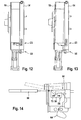
- the sliding gate valve 10 is provided with a pressure reduction device for controlled reduction of the operative contact pressure as mentioned above and shown in Figs.9-14.
- a pressure reduction device for controlled reduction of the operative contact pressure as mentioned above and shown in Figs.9-14.
- similar or identical parts are identified by the same reference numerals in Figs.9-14.
- a pressure reduction device 50 as shown in Fig.9 comprises a catch and stopper contrivance to limit the opening swing of the housing 12.
- Fig.9 shows the pressure reduction device 50 which comprises a catch 52 and a stopper 54.
- the catch 52 is pivotably mounted to the cover 14 by means of a shaft 56.
- the stopper 54 comprises a base plate 58 mounted to the frame 16 and a protrusion 60 fixed to the base plate 58.
- the catch 52 has a tooth 62 which is arranged to engage the protrusion 60 of the stopper 56.
- the catch 52 is forced against the protrusion 60 by suitable resilient means or, if suitably arranged, simply by gravitation.
- Figs. 12 to 13 are side views according to arrow XII in Fig.9.
- the hinge 18 is arranged on the on the short side of the housing 12 in the sliding gate valve 10 of Figs.9-13.
- Fig.9 also shows a collector nozzle 66 mounted to the rotatable slide plate support 24 (not shown in Fig.9) in sealing contact downstream of the slide plate 20.
- the lock device 23 shown in Fig.9 is adapted to lateral opening of the housing 12.
- the sliding gate valve 10 is normally mounted to the metallurgical vessel and located at a service site when controlled partial decompression by use of the pressure reduction device 50 is carried out.
- the sliding gate valve 10 is oriented vertically as shown in the Figs.9-14.
- the lock device 23 and the pressure reduction device 50 are arranged such that manipulations can be easily carried out in this configuration.
- the second coupling 48 is arranged so as to be easily accessible.
- a tool 68 is used to disengage the catch 52 and the stopper 54 into the position indicated by shaded lines.
- the catch 52 has a bore corresponding to the tip of the tool 68.
- the same tool 68 is used in combination with the levers 64 of the lock device 23, which comprise similar bores.
- the base plate 58 of the stopper 54 comprises elongated slots 70, which allow precise adjusting of the allowed displacement 63 and consequently the amount of contact pressure reduction. It may be noted that the span is chosen such as to maintain a predetermined contact between the slide plate 20 and the fixed plate 22. By allowing a relatively small displacement, the pressure reduction device 50 insures controlled reduction of the operative contact pressure. It also prevents accidental opening of the housing 12.
- Fig.3 is a plan view of a sliding gate valve 10 with a ratchet mechanism 140 according to a second embodiment.
- the ratchet mechanism 140 is mounted to the slideable tray 26 and comprises a ratchet wheel 142, a pusher 144 and a pawl 146.
- the ratchet wheel 142 is provided with a plurality of indentations 150 which are inclined with respect to the radius of the ratchet wheel 142.
- the ratchet mechanism 140 is arranged to rotate the slide plate 20 in defined discrete steps 151, e.g. 15° in this embodiment, and warrants a defined angular position of the slide plate 20.
- the ratchet mechanism 140 of Fig.3 is shown in more detail in Fig. 4.
- Plain bearing mounts 152, 152' are fixed to the slideable tray 26 for guiding the pusher 144.
- Adjustable limit stops 154, 154' are provided on the plain bearing mounts 152, 152' to limit the stroke of the pusher 144 to a predetermined range in both directions indicated by arrows 45 and 45'.
- the limit stops 154, 154' cooperate with corresponding abutments 156, 156' fixed to the pusher 144.
- the pawl 146 is pivotable about a shaft 158 on the pusher 144.
- a first spring 160 warrants that the pawl 146 engages a given indentation 150 during rotation.
- a second spring 162 is provided inside the coupling 48.
- the second spring 162 is supported by the slideable tray 26 and acts on the pusher 144 via a connecting rod 163. Without action of a linear actuator coupled to coupling 48, the second spring 162 urges the pusher 144 into the position shown in Figs.3, 4 and 15.
- the second spring 162 is protected by the coupling 48 against detrimental influences.
- similar or identical parts are identified by the same reference numerals in Fig. 15. It may be noted that Fig. 15 further shows the collector nozzle 66 and a protective sheet metal lid 67 which is absent in the views of Fig.1 to 3.
- an adjustable blocking member 164 is fixed to the pusher 144 and protrudes perpendicularly towards the ratchet wheel 142. In the position as seen in Figs.3 and 4, the blocking member 164 engages a certain indentation 150' of the ratchet wheel 142.
- the blocking member 164 and the second spring 162 form a blocking mechanism for blocking rotation of the slide plate 20 in the allowed sense according to arrow 49. Additional blocking in the allowed sense 49 may be required if the aforementioned operative contact pressure does not sufficiently impede rotation in the allowed sense 49 or if significant torques can occur during operation.
- the blocking member 164 also blocks rotation in the opposite sense, since the pawl 146 is not fully engaging the ratchet wheel 142.
- the second spring 162 is pre-tensioned and its spring constant is chosen such as to warrant a blocking engagement between the blocking member 164 and the ratchet wheel 142.
- the second spring 162 can be compressed.
- the blocking member 164 is disengaged such that rotation in the allowed sense 49 is permitted.
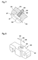
- the slide plate 20 as best seen in Fig.5 comprises a one piece circular disc 20' made of refractory material (e.g. alumina, zirconia, silica, magnesia, carbon or any suitable combination thereof) and having a axial circular central orifice, i.e. the first orifice 30.
- the disc 20' is provided with a circumferential steel band 20" made of a suitable steel. In a manner known per se, the steel band 20" is shrinkage fitted to the disc 20', to insure cohesion of the disc 20' even in case of cracking.
- the chosen parameters of the slide plate 20 are: outer diameter 450mm; orifice diameter 90mm; refractory thickness 40mm; steel band thickness 5mm and shrinkage fit at 1000°C. These values depend on the actual requirements however and can be chosen differently. Since the slide plate 20 is rotationally symmetrical, there is no preferred orientation and it can be readily rotated. More specifically, the refractory disc 20' is made so as to be isotropic to the most possible extent. The preferred mode of rotation and the function of the ratchet mechanism 40, 140 will be more apparent from the following description of Fig.5.
- a first area of localised wear is identified by reference numeral 200 (indicated by shading).
- the area 200 forms the part of the slide plate 20 that is slid underneath the second orifice 32 and its length corresponds to the sliding range indicated at 202.
- the area 200 is at least partially located within the molten metal flow.
- the area 200 is subjected to significant erosion and corrosion.
- wear of the area 200 increases towards the first orifice 30, which results in the know symptom that the first orifice 30 grows in the direction of arrow 28.
- the ratchet mechanism 40, 140 allows to rotate the slide plate 20 according to arrow 49.
- the ratchet wheel 142 is provided with 24 indentations such that a discrete rotational step of 15° results from each stroke of the pusher 144.
- a linear actuator coupled to the ratchet mechanism 40, 140 allows to place a previously unworn area 204, 206, 208 (indicated by shading) within the sliding range 202 and underneath the second orifice 32.
- An automated system normally controls the linear actuator.
- one or more operational parameters of the linear actuator e.g. a hydraulic cylinder
- these parameters include for example the effective piston displacement, the duration spent for a given displacement, the pressure in both chambers of the hydraulic cylinder and the duration and/or variation in time of these pressures.
- a pressure level above a defined permissible range indicates jamming or gripping of the plates 20, 22 or other mechanical components of the sliding gate valve 10.
- pressure levels below the permissible range indicate a rupture of the cinematic chain of the ratchet mechanism 40, 140.
- a factor which is preferably taken into account is the effective contact pressure during rotation, e.g. by knowledge of the settings of the pressurizing devices 36, 36' and, if applicable, of the pressure reduction device 50.
- This auto-control of the ratchet mechanism 40, 140 and its linear actuator allows to detect a possible failure and thus contributes to insuring predetermined angular positions of the slide plate 20 throughout its working life.
- history information is generated in the information system by taking into account mechanical parameters of the sliding gate valve 10 measured in the maintenance shop, at the service site and at the casting site. This history information is used as input for an operation control device of the sliding gate valve 10 and also for scheduling preventive maintenance. History information allows to optimise use and design of the sliding gate valve 10 in general, and in particular the rotation schedule in order to minimize wear of the slide plate 20. For example, such empirical data on the sliding gate valve 10 allows maximizing the operational time of its constituting parts, in particular the plates 20, 22, by avoiding premature replacement. Moreover history information increases safety of operation by scheduling necessary maintenance in due time.
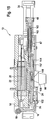
- Figs.6-8 show the details of a clamping ring 300 according to a third embodiment.
- the clamping ring 300 is designed in accordance with the above findings and independent of the ratchet mechanism 40, 140.
- the slide plate 20 in the sliding gate valve 10 of Fig.6 corresponds to the slide plate 20 of Fig. 5. It comprises a disc shaped refractory 20' rimmed by a steel band 20" and has a central orifice, i.e. the first orifice 30.
- the clamping ring 300 allows to secure the slide plate 20 to the rotatable slide plate support 24 which is rotatable on the slideable tray 26.
- the clamping ring 300 comprises 4 circular arc shaped rigid links 302 and a mounting block 304.
- the rigid links 302 and the mounting block 304 are interconnected by means of revolute joint type articulations 306 allowing relative rotation about axes perpendicular to the plane of Fig.6.
- a small tenon 308 is fixed to the steel band 20" which fits into a mortise 310 in the mounting block 304.
- the tenon 308 (also shown in Fig.5) cooperates with the mortise 310 so as to block the slide plate 20 in rotation with respect to the clamping ring 300 without blocking radial expansion of the slide plate 20 in the region of the tenon 308.
- the depth of mortise 310 is larger than the height of tenon 308. It may be noted that the tenon 308 allows to block the slide plate 20 in rotation without the necessity to modify the circular shape of the refractory disc 20'.
- the clamping ring 300 is blocked in rotation on the slide plate support 24 by means of the mounting block 304.
- a plurality of resilient fastening members 320 are disposed in rotational symmetry on the circumference of the clamping ring 300.
- the fastening members 320 resiliently fasten the slide plate 20 relative to the clamping ring 300 in order to allow a certain amount of radial dilatation during operation.
- in total 9 resilient fastening members 320 are arranged in the clamping ring 300, i.e. they are disposed at regular angles of 40° as indicated at 321.
- a sufficient number of radial fixation points allows to reduce tensile stresses in the slide plate 20.
- the resilient fastening members 320 also have a replacement function of the steel band 20" which, as has been found, tends to become plastically deformable to an unacceptable degree at the high operating temperatures of the sliding gate valve 10.
- Each resilient fastening member 320 comprises a helical spring 322 supported by the respective rigid link 302 and pressing against a fastening element 324.
- helical springs 322 are described other suitable means such as disc springs or pneumatic mounts are not excluded.
- a threaded shaft 326 is fixed to the fastening element 324 and protrudes through a corresponding bore in the clamping ring 300.
- a nut 328 allows to pre-tension the helical spring 322 so as to maintain a rigid fixation of the slide plate up to a certain degree of dilatation. Any dilatation in excess of what corresponds to the predetermined prestress of the helical spring 322 is allowed up to the width of the radial clearance indicated at 330.
- the clamping ring 300 in combination with the fastening members 320 as shown in Fig.7 insures a sufficient fixation of the slide plate 20 while allowing a certain amount of radial dilatation.
- the clamping ring 300 is provided with an all-or-nothing type closure 340 in the region radially opposed to the mounting block 304.
- the clamping ring 300 and the closure 340 are designed so as to simplify the exchange of slide plate 20 and to preclude deregulation of the pre-tensioned fastening thereof.
- It comprises a lock 342 which is best seen in Fig. 8.
- the lock 342 is pivotably mounted to an end of one of the rigid links 302 by an axis 343 and engages a corresponding cavity in the end of the opposite link 302.
- the lock 342 has a bore 344 perpendicular to its pivot axis 343 which allows to use the tool 68 according to arrows 345 for opening and closing the clamping ring 300.
- the closure 340 in combination with the articulations 306 allows to widen the clamping ring 300 for exchange of the slide plate 20. It will be appreciated that the articulations 306, in combination with the resilient fastening members 320, insure auto-centering of the slide plate 20 with respect to the clamping ring 300 and accordingly the slideable tray 26. Although not shown, obviously a similar clamping ring is advantageously used for the fixed plate 22 in the sliding gate valve 10.
- slide plate 20 and the fixed plate 22 have an identical configuration, i.e. identical dimensions. More specifically, besides rotational symmetry, both plates 20, 22 are symmetrical with respect to a central diametrical plane of symmetry. A used slide plate 20 may thus be utilized as fixed plate 22 and vice versa, so as to present its previously inactive surface as fresh active surface. If required, previous machining of the respective plate 20, 22 can be carried out. It will be appreciated that prolonged working life and reduced wear obtained with the presently disclosed sliding gate valve 10 contribute to the reuse capacity of the plates 20, 22.
Landscapes
- Engineering & Computer Science (AREA)
- Mechanical Engineering (AREA)
- Casting Support Devices, Ladles, And Melt Control Thereby (AREA)
- Sliding Valves (AREA)
- Furnace Charging Or Discharging (AREA)
Priority Applications (2)
| Application Number | Priority Date | Filing Date | Title |
|---|---|---|---|
| PL07121932T PL1900459T3 (pl) | 2005-03-10 | 2006-01-12 | Liniowy suwakowy wylew do naczynia metalurgicznego |
| EP07121932A EP1900459B1 (de) | 2005-03-10 | 2006-01-12 | Linearer Schieberverschluss ein metallurgisches Gefäß |
Applications Claiming Priority (3)
| Application Number | Priority Date | Filing Date | Title |
|---|---|---|---|
| EP05101886A EP1707291A1 (de) | 2005-03-10 | 2005-03-10 | Schiebeverschluss |
| EP06700706A EP1863606B1 (de) | 2005-03-10 | 2006-01-12 | Linearer absperrschieber für ein metallurgisches gefäss |
| EP07121932A EP1900459B1 (de) | 2005-03-10 | 2006-01-12 | Linearer Schieberverschluss ein metallurgisches Gefäß |
Related Parent Applications (2)
| Application Number | Title | Priority Date | Filing Date |
|---|---|---|---|
| EP06700706A Division EP1863606B1 (de) | 2005-03-10 | 2006-01-12 | Linearer absperrschieber für ein metallurgisches gefäss |
| EP06700706.2 Division | 2006-01-12 |
Publications (3)
| Publication Number | Publication Date |
|---|---|
| EP1900459A2 true EP1900459A2 (de) | 2008-03-19 |
| EP1900459A3 EP1900459A3 (de) | 2008-05-14 |
| EP1900459B1 EP1900459B1 (de) | 2011-11-23 |
Family
ID=34938944
Family Applications (3)
| Application Number | Title | Priority Date | Filing Date |
|---|---|---|---|
| EP05101886A Withdrawn EP1707291A1 (de) | 2005-03-10 | 2005-03-10 | Schiebeverschluss |
| EP07121932A Expired - Lifetime EP1900459B1 (de) | 2005-03-10 | 2006-01-12 | Linearer Schieberverschluss ein metallurgisches Gefäß |
| EP06700706A Expired - Lifetime EP1863606B1 (de) | 2005-03-10 | 2006-01-12 | Linearer absperrschieber für ein metallurgisches gefäss |
Family Applications Before (1)
| Application Number | Title | Priority Date | Filing Date |
|---|---|---|---|
| EP05101886A Withdrawn EP1707291A1 (de) | 2005-03-10 | 2005-03-10 | Schiebeverschluss |
Family Applications After (1)
| Application Number | Title | Priority Date | Filing Date |
|---|---|---|---|
| EP06700706A Expired - Lifetime EP1863606B1 (de) | 2005-03-10 | 2006-01-12 | Linearer absperrschieber für ein metallurgisches gefäss |
Country Status (21)
| Country | Link |
|---|---|
| US (1) | US7648053B2 (de) |
| EP (3) | EP1707291A1 (de) |
| JP (1) | JP4734405B2 (de) |
| KR (1) | KR101239905B1 (de) |
| CN (1) | CN101146636B (de) |
| AR (1) | AR052683A1 (de) |
| AT (2) | ATE534479T1 (de) |
| AU (1) | AU2006222134B2 (de) |
| BR (1) | BRPI0608041A2 (de) |
| CA (1) | CA2601252A1 (de) |
| DE (1) | DE602006002376D1 (de) |
| EA (2) | EA010251B1 (de) |
| EG (1) | EG24647A (de) |
| ES (2) | ES2313603T3 (de) |
| MX (1) | MX2007011106A (de) |
| MY (1) | MY138004A (de) |
| NZ (1) | NZ561453A (de) |
| PL (2) | PL1863606T3 (de) |
| TW (1) | TWI372664B (de) |
| WO (1) | WO2006094846A1 (de) |
| ZA (1) | ZA200708107B (de) |
Families Citing this family (17)
| Publication number | Priority date | Publication date | Assignee | Title |
|---|---|---|---|---|
| EP1707291A1 (de) | 2005-03-10 | 2006-10-04 | Tech-Gate S.A. | Schiebeverschluss |
| US8448657B2 (en) * | 2010-04-26 | 2013-05-28 | Red Mountain Engineering Llc | Passive-cycle skipping valve |
| BR112013024960B1 (pt) * | 2011-03-30 | 2020-01-28 | Krosakiharima Corp | placa, e, estrutura de fixação de placa |
| CH707075B1 (de) * | 2012-10-11 | 2021-01-15 | Refractory Intellectual Property Gmbh & Co Kg | Schiebeverschluss für ein Metallschmelze enthaltendes Gefäss. |
| US9377037B2 (en) | 2013-03-15 | 2016-06-28 | Ron R. Daniels | Lock device and method of use |
| CN103990789B (zh) * | 2014-04-16 | 2015-11-04 | 宁国东方碾磨材料股份有限公司 | 一种用于支撑水口砖的托盘 |
| CH710094A2 (de) * | 2014-09-11 | 2016-03-15 | Refractory Intellectual Prop | Schiebeverschluss für ein metallurgisches Gefäss. |
| CH710652B1 (de) * | 2015-01-23 | 2019-06-28 | Refractory Intellectual Property Gmbh & Co Kg | Schiebeverschluss für einen Metallschmelze enthaltenden Behälter. |
| CN105665690B (zh) * | 2016-03-03 | 2017-12-08 | 无锡双木机械科技有限公司 | 一种安全高效门式自动加压滑动水口机构 |
| RU172571U1 (ru) * | 2016-10-31 | 2017-07-13 | Акционерное общество "ЕВРАЗ Объединенный Западно-Сибирский металлургический комбинат", АО "ЕВРАЗ ЗСМК" | Шиберный затвор для сталеразливочных ковшей |
| RU2645851C1 (ru) * | 2017-03-17 | 2018-02-28 | Общество с ограниченной ответственностью "Кералит" | Плита шиберного затвора и способ ее изготовления |
| RU2699467C1 (ru) * | 2019-02-21 | 2019-09-05 | Общество с ограниченной ответственностью "Кералит" | Плита шиберного затвора и способ ее изготовления |
| CN111623131B (zh) * | 2019-02-28 | 2025-09-16 | 维苏威集团有限公司 | 包括托架的滑动闸阀 |
| US11331719B2 (en) * | 2020-02-28 | 2022-05-17 | Knöllinger FLO-TEC GmbH | Slide gate with compensation device for the contact pressure |
| CN112355298A (zh) * | 2020-11-09 | 2021-02-12 | 芜湖新兴铸管有限责任公司 | 连铸中间包事故闸板装置 |
| CN112665386B (zh) * | 2020-11-30 | 2022-03-04 | 江苏省镔鑫钢铁集团有限公司 | 一种超微晶带生产用炼钢炉的水口防堵塞装置 |
| JP6940721B1 (ja) * | 2021-02-08 | 2021-09-29 | Tpr株式会社 | 鋳造システム |
Citations (6)
| Publication number | Priority date | Publication date | Assignee | Title |
|---|---|---|---|---|
| US3764042A (en) | 1972-08-03 | 1973-10-09 | United States Steel Corp | Reciprocable slidable gate with rotating slide element |
| US4187965A (en) | 1977-06-06 | 1980-02-12 | Sanac Societa Per Azioni Refrattari Argille E Calolini | Box discharger comprising reloadable refractory plates, with wedge locking |
| EP0222978A1 (de) | 1985-10-30 | 1987-05-27 | Didier-Werke Ag | Feuerfeste Verschleissplatte für Schieberverschlüsse an metallurgischen Gefässen |
| DE3805074C1 (de) | 1988-01-15 | 1989-09-21 | Stopinc Ag, Baar, Ch | |
| EP0346258A2 (de) | 1988-05-13 | 1989-12-13 | Edouard Detalle | Giessverschluss zur linearen und symmetrie-axialen Verstellung |
| EP1863606A1 (de) | 2005-03-10 | 2007-12-12 | Tech-Gate S.A. | Linearer absperrschieber für ein metallurgisches gefäss |
Family Cites Families (23)
| Publication number | Priority date | Publication date | Assignee | Title |
|---|---|---|---|---|
| US3430644A (en) * | 1967-02-24 | 1969-03-04 | United States Steel Corp | Rotary gate for bottom pour vessel |
| JPS4987912U (de) * | 1972-11-18 | 1974-07-30 | ||
| DE2260142C3 (de) * | 1972-12-08 | 1975-12-11 | Motoren- Und Turbinen-Union Friedrichshafen Gmbh, 7990 Friedrichshafen | Zylinder-Kurbelgehäuse |
| JPS5141974B2 (de) * | 1973-02-12 | 1976-11-12 | ||
| US4013090A (en) * | 1975-11-10 | 1977-03-22 | Taylor Julian S | Gate valve rotating disc |
| JPS5426236A (en) * | 1977-08-01 | 1979-02-27 | Nippon Kokan Kk | Method and apparatus for rotaryytype sliding openingganddclosing |
| JPS5426238A (en) * | 1977-08-01 | 1979-02-27 | Nippon Kokan Kk | Method and apparatus for rotaryytype sliding openingganddclosing |
| ZA785844B (en) * | 1977-11-15 | 1979-09-26 | Vesuvius Int Corp | Revolving slide gate mechanism |
| GB1595815A (en) * | 1978-03-21 | 1981-08-19 | Vesuvius Int Corp | Flow control device for molten metal |
| US4278473A (en) * | 1979-08-24 | 1981-07-14 | Varian Associates, Inc. | Monolithic series-connected solar cell |
| CH654769A5 (de) * | 1981-07-15 | 1986-03-14 | Stopinc Ag | Drehschiebeverschluss fuer einen schmelzebehaelter. |
| GB2117489B (en) * | 1982-03-05 | 1985-06-05 | Nippon Kokan Kk | Dual door type rotary nozzle |
| GB2133505B (en) * | 1982-12-14 | 1987-04-15 | Nippon Kokan Kk | Rotary nozzle system for metallurgical vessels |
| DE3423157C1 (de) * | 1984-06-22 | 1985-06-20 | Metacon AG, Zürich | Feuerfestes Plattenpaar fuer schwenk- bzw. drehbewegliche Schiebeverschluesse |
| CA1279189C (en) * | 1985-11-18 | 1991-01-22 | Tetsuya Yoshihara | Rotary nozzle system |
| ATE72528T1 (de) * | 1988-06-09 | 1992-02-15 | Hepworth Refractories Belgium | Verfahren zur reglung des durchsatzes an einem schieber und schieber fuer die durchfuehrung dieses verfahrens. |
| JPH0252165A (ja) * | 1988-08-12 | 1990-02-21 | Nippon Rootarii Nozuru Kk | ロータリーノズル |
| JP2805559B2 (ja) * | 1992-01-29 | 1998-09-30 | 鋼管機械工業株式会社 | ロータリノズル |
| FR2713525A1 (fr) | 1993-12-07 | 1995-06-16 | Detalle Anne | Procédé de serrage isostatique pour plaques de fermeture à tiroir et autres éléments. |
| BE1008119A3 (fr) * | 1994-03-21 | 1996-01-23 | Szadkowski Stanislav | Dispositif de regulation de debit a fermeture coulissante d'un recipient metallurgique. |
| ZA975908B (en) * | 1996-07-18 | 1998-03-30 | Stopinc Ag | Sliding gate valve for a vessel containing molten metal. |
| ATE258090T1 (de) * | 1997-04-30 | 2004-02-15 | Stopinc Ag | Schiebeverschluss für ein metallschmelze enthaltendes gefäss |
| CA2463944A1 (en) * | 2001-11-13 | 2003-05-22 | Vesuvius Crucible Company | Multi-hole, multi-edge control plate for linear sliding gate |
-
2005
- 2005-03-10 EP EP05101886A patent/EP1707291A1/de not_active Withdrawn
-
2006
- 2006-01-12 PL PL06700706T patent/PL1863606T3/pl unknown
- 2006-01-12 CN CN2006800090779A patent/CN101146636B/zh not_active Expired - Fee Related
- 2006-01-12 ES ES06700706T patent/ES2313603T3/es not_active Expired - Lifetime
- 2006-01-12 KR KR1020077023170A patent/KR101239905B1/ko not_active Expired - Fee Related
- 2006-01-12 WO PCT/EP2006/050171 patent/WO2006094846A1/en not_active Ceased
- 2006-01-12 EP EP07121932A patent/EP1900459B1/de not_active Expired - Lifetime
- 2006-01-12 BR BRPI0608041-3A patent/BRPI0608041A2/pt not_active Application Discontinuation
- 2006-01-12 EA EA200701891A patent/EA010251B1/ru not_active IP Right Cessation
- 2006-01-12 AT AT07121932T patent/ATE534479T1/de active
- 2006-01-12 CA CA002601252A patent/CA2601252A1/en not_active Abandoned
- 2006-01-12 EP EP06700706A patent/EP1863606B1/de not_active Expired - Lifetime
- 2006-01-12 JP JP2008500139A patent/JP4734405B2/ja not_active Expired - Fee Related
- 2006-01-12 EA EA200801060A patent/EA013176B1/ru not_active IP Right Cessation
- 2006-01-12 DE DE602006002376T patent/DE602006002376D1/de not_active Expired - Fee Related
- 2006-01-12 AT AT06700706T patent/ATE405362T1/de active
- 2006-01-12 NZ NZ561453A patent/NZ561453A/en not_active IP Right Cessation
- 2006-01-12 PL PL07121932T patent/PL1900459T3/pl unknown
- 2006-01-12 US US11/908,265 patent/US7648053B2/en not_active Expired - Fee Related
- 2006-01-12 AU AU2006222134A patent/AU2006222134B2/en not_active Ceased
- 2006-01-12 ES ES07121932T patent/ES2377460T3/es not_active Expired - Lifetime
- 2006-01-12 MX MX2007011106A patent/MX2007011106A/es active IP Right Grant
- 2006-02-24 TW TW095106225A patent/TWI372664B/zh not_active IP Right Cessation
- 2006-02-27 MY MYPI20060831A patent/MY138004A/en unknown
- 2006-03-08 AR ARP060100863A patent/AR052683A1/es active IP Right Grant
-
2007
- 2007-09-09 EG EGNA2007000951 patent/EG24647A/xx active
- 2007-09-20 ZA ZA200708107A patent/ZA200708107B/xx unknown
Patent Citations (6)
| Publication number | Priority date | Publication date | Assignee | Title |
|---|---|---|---|---|
| US3764042A (en) | 1972-08-03 | 1973-10-09 | United States Steel Corp | Reciprocable slidable gate with rotating slide element |
| US4187965A (en) | 1977-06-06 | 1980-02-12 | Sanac Societa Per Azioni Refrattari Argille E Calolini | Box discharger comprising reloadable refractory plates, with wedge locking |
| EP0222978A1 (de) | 1985-10-30 | 1987-05-27 | Didier-Werke Ag | Feuerfeste Verschleissplatte für Schieberverschlüsse an metallurgischen Gefässen |
| DE3805074C1 (de) | 1988-01-15 | 1989-09-21 | Stopinc Ag, Baar, Ch | |
| EP0346258A2 (de) | 1988-05-13 | 1989-12-13 | Edouard Detalle | Giessverschluss zur linearen und symmetrie-axialen Verstellung |
| EP1863606A1 (de) | 2005-03-10 | 2007-12-12 | Tech-Gate S.A. | Linearer absperrschieber für ein metallurgisches gefäss |
Also Published As
Similar Documents
| Publication | Publication Date | Title |
|---|---|---|
| EP1900459B1 (de) | Linearer Schieberverschluss ein metallurgisches Gefäß | |
| EP0080672B1 (de) | SchiebeverschluB | |
| US4233718A (en) | Method for applying a desired sealing pressure between refractory plates of sliding nozzle | |
| US4887748A (en) | Apparatus and method for attachment of submerged nozzle to lower plate of sliding gate valve mechanism for a continuous casting operation | |
| CN112334251A (zh) | 用于冶金容器的、优选用于连铸系统的中间包的滑动封闭件 | |
| AU694651B2 (en) | Sliding gate valve | |
| US5429342A (en) | Slide gate nozzle including sequentially replaceable refractory sliding plates and refractory plate assembly employable therein | |
| CA2403849A1 (en) | Clamping device for a refractory-made plate of a sliding gate | |
| AU2001246254A1 (en) | Clamping device for a refractory-made plate of a sliding gate | |
| EP3261787A1 (de) | Schale zum ersatz einer feuerfesten giessplatte für ein metallurgisches gefäss | |
| EP0559832B1 (de) | Schieber | |
| RU2805407C1 (ru) | Шиберный затвор | |
| PL173289B1 (pl) | Urządzenie do sterowania szybkością wypływu | |
| RU2798379C2 (ru) | Шиберный затвор для металлургического контейнера, предпочтительно промежуточного ковша для системы непрерывного литья | |
| AU653987B2 (en) | Vessel outlet | |
| US20130048897A1 (en) | Exchangeable valve plate assembly for a molten metal slide gate valve | |
| GB2112905A (en) | Improvements in sliding gate valves | |
| JPS58141845A (ja) | 溶湯の注入に使用する滑り仕切弁 | |
| PL230624B1 (pl) | Klin dwudzielny zasuwy |
Legal Events
| Date | Code | Title | Description |
|---|---|---|---|
| PUAI | Public reference made under article 153(3) epc to a published international application that has entered the european phase |
Free format text: ORIGINAL CODE: 0009012 |
|
| AC | Divisional application: reference to earlier application |
Ref document number: 1863606 Country of ref document: EP Kind code of ref document: P |
|
| AK | Designated contracting states |
Kind code of ref document: A2 Designated state(s): AT BE BG CH CY CZ DE DK EE ES FI FR GB GR HU IE IS IT LI LT LU LV MC NL PL PT RO SE SI SK TR |
|
| AX | Request for extension of the european patent |
Extension state: AL BA HR MK YU |
|
| PUAL | Search report despatched |
Free format text: ORIGINAL CODE: 0009013 |
|
| AK | Designated contracting states |
Kind code of ref document: A3 Designated state(s): AT BE BG CH CY CZ DE DK EE ES FI FR GB GR HU IE IS IT LI LT LU LV MC NL PL PT RO SE SI SK TR |
|
| AX | Request for extension of the european patent |
Extension state: AL BA HR MK YU |
|
| 17P | Request for examination filed |
Effective date: 20081114 |
|
| AKX | Designation fees paid |
Designated state(s): AT BE BG CH CY CZ DE DK EE ES FI FR GB GR HU IE IS IT LI LT LU LV MC NL PL PT RO SE SI SK TR |
|
| 17Q | First examination report despatched |
Effective date: 20090219 |
|
| GRAP | Despatch of communication of intention to grant a patent |
Free format text: ORIGINAL CODE: EPIDOSNIGR1 |
|
| GRAS | Grant fee paid |
Free format text: ORIGINAL CODE: EPIDOSNIGR3 |
|
| GRAA | (expected) grant |
Free format text: ORIGINAL CODE: 0009210 |
|
| RAP1 | Party data changed (applicant data changed or rights of an application transferred) |
Owner name: GB TECH S.R.L. |
|
| AC | Divisional application: reference to earlier application |
Ref document number: 1863606 Country of ref document: EP Kind code of ref document: P |
|
| AK | Designated contracting states |
Kind code of ref document: B1 Designated state(s): AT BE BG CH CY CZ DE DK EE ES FI FR GB GR HU IE IS IT LI LT LU LV MC NL PL PT RO SE SI SK TR |
|
| REG | Reference to a national code |
Ref country code: GB Ref legal event code: FG4D |
|
| REG | Reference to a national code |
Ref country code: CH Ref legal event code: EP |
|
| REG | Reference to a national code |
Ref country code: IE Ref legal event code: FG4D |
|
| REG | Reference to a national code |
Ref country code: RO Ref legal event code: EPE Ref country code: DE Ref legal event code: R096 Ref document number: 602006026078 Country of ref document: DE Effective date: 20120209 |
|
| REG | Reference to a national code |
Ref country code: SE Ref legal event code: TRGR |
|
| REG | Reference to a national code |
Ref country code: NL Ref legal event code: T3 Ref country code: CH Ref legal event code: NV Representative=s name: ISLER & PEDRAZZINI AG |
|
| REG | Reference to a national code |
Ref country code: ES Ref legal event code: FG2A Ref document number: 2377460 Country of ref document: ES Kind code of ref document: T3 Effective date: 20120327 |
|
| LTIE | Lt: invalidation of european patent or patent extension |
Effective date: 20111123 |
|
| PG25 | Lapsed in a contracting state [announced via postgrant information from national office to epo] |
Ref country code: LT Free format text: LAPSE BECAUSE OF FAILURE TO SUBMIT A TRANSLATION OF THE DESCRIPTION OR TO PAY THE FEE WITHIN THE PRESCRIBED TIME-LIMIT Effective date: 20111123 Ref country code: IS Free format text: LAPSE BECAUSE OF FAILURE TO SUBMIT A TRANSLATION OF THE DESCRIPTION OR TO PAY THE FEE WITHIN THE PRESCRIBED TIME-LIMIT Effective date: 20120323 |
|
| REG | Reference to a national code |
Ref country code: PL Ref legal event code: T3 |
|
| PG25 | Lapsed in a contracting state [announced via postgrant information from national office to epo] |
Ref country code: PT Free format text: LAPSE BECAUSE OF FAILURE TO SUBMIT A TRANSLATION OF THE DESCRIPTION OR TO PAY THE FEE WITHIN THE PRESCRIBED TIME-LIMIT Effective date: 20120323 Ref country code: SI Free format text: LAPSE BECAUSE OF FAILURE TO SUBMIT A TRANSLATION OF THE DESCRIPTION OR TO PAY THE FEE WITHIN THE PRESCRIBED TIME-LIMIT Effective date: 20111123 Ref country code: LV Free format text: LAPSE BECAUSE OF FAILURE TO SUBMIT A TRANSLATION OF THE DESCRIPTION OR TO PAY THE FEE WITHIN THE PRESCRIBED TIME-LIMIT Effective date: 20111123 Ref country code: GR Free format text: LAPSE BECAUSE OF FAILURE TO SUBMIT A TRANSLATION OF THE DESCRIPTION OR TO PAY THE FEE WITHIN THE PRESCRIBED TIME-LIMIT Effective date: 20120224 |
|
| PGFP | Annual fee paid to national office [announced via postgrant information from national office to epo] |
Ref country code: TR Payment date: 20120220 Year of fee payment: 7 |
|
| PG25 | Lapsed in a contracting state [announced via postgrant information from national office to epo] |
Ref country code: CY Free format text: LAPSE BECAUSE OF FAILURE TO SUBMIT A TRANSLATION OF THE DESCRIPTION OR TO PAY THE FEE WITHIN THE PRESCRIBED TIME-LIMIT Effective date: 20111123 |
|
| PGFP | Annual fee paid to national office [announced via postgrant information from national office to epo] |
Ref country code: RO Payment date: 20120130 Year of fee payment: 7 |
|
| PG25 | Lapsed in a contracting state [announced via postgrant information from national office to epo] |
Ref country code: SK Free format text: LAPSE BECAUSE OF FAILURE TO SUBMIT A TRANSLATION OF THE DESCRIPTION OR TO PAY THE FEE WITHIN THE PRESCRIBED TIME-LIMIT Effective date: 20111123 Ref country code: EE Free format text: LAPSE BECAUSE OF FAILURE TO SUBMIT A TRANSLATION OF THE DESCRIPTION OR TO PAY THE FEE WITHIN THE PRESCRIBED TIME-LIMIT Effective date: 20111123 Ref country code: BG Free format text: LAPSE BECAUSE OF FAILURE TO SUBMIT A TRANSLATION OF THE DESCRIPTION OR TO PAY THE FEE WITHIN THE PRESCRIBED TIME-LIMIT Effective date: 20120223 Ref country code: DK Free format text: LAPSE BECAUSE OF FAILURE TO SUBMIT A TRANSLATION OF THE DESCRIPTION OR TO PAY THE FEE WITHIN THE PRESCRIBED TIME-LIMIT Effective date: 20111123 |
|
| PG25 | Lapsed in a contracting state [announced via postgrant information from national office to epo] |
Ref country code: MC Free format text: LAPSE BECAUSE OF NON-PAYMENT OF DUE FEES Effective date: 20120131 |
|
| PLBE | No opposition filed within time limit |
Free format text: ORIGINAL CODE: 0009261 |
|
| STAA | Information on the status of an ep patent application or granted ep patent |
Free format text: STATUS: NO OPPOSITION FILED WITHIN TIME LIMIT |
|
| REG | Reference to a national code |
Ref country code: IE Ref legal event code: MM4A |
|
| 26N | No opposition filed |
Effective date: 20120824 |
|
| REG | Reference to a national code |
Ref country code: DE Ref legal event code: R097 Ref document number: 602006026078 Country of ref document: DE Effective date: 20120824 |
|
| PG25 | Lapsed in a contracting state [announced via postgrant information from national office to epo] |
Ref country code: IE Free format text: LAPSE BECAUSE OF NON-PAYMENT OF DUE FEES Effective date: 20120112 |
|
| PGFP | Annual fee paid to national office [announced via postgrant information from national office to epo] |
Ref country code: PL Payment date: 20121218 Year of fee payment: 8 Ref country code: LU Payment date: 20130131 Year of fee payment: 8 |
|
| PGFP | Annual fee paid to national office [announced via postgrant information from national office to epo] |
Ref country code: FR Payment date: 20130211 Year of fee payment: 8 Ref country code: FI Payment date: 20130129 Year of fee payment: 8 Ref country code: CZ Payment date: 20121231 Year of fee payment: 8 Ref country code: DE Payment date: 20130129 Year of fee payment: 8 Ref country code: GB Payment date: 20130125 Year of fee payment: 8 Ref country code: SE Payment date: 20130129 Year of fee payment: 8 |
|
| PGFP | Annual fee paid to national office [announced via postgrant information from national office to epo] |
Ref country code: AT Payment date: 20121219 Year of fee payment: 8 |
|
| PGFP | Annual fee paid to national office [announced via postgrant information from national office to epo] |
Ref country code: BE Payment date: 20140127 Year of fee payment: 9 Ref country code: NL Payment date: 20140126 Year of fee payment: 9 Ref country code: CH Payment date: 20140129 Year of fee payment: 9 |
|
| PGFP | Annual fee paid to national office [announced via postgrant information from national office to epo] |
Ref country code: IT Payment date: 20140128 Year of fee payment: 9 Ref country code: ES Payment date: 20140127 Year of fee payment: 9 |
|
| PG25 | Lapsed in a contracting state [announced via postgrant information from national office to epo] |
Ref country code: HU Free format text: LAPSE BECAUSE OF FAILURE TO SUBMIT A TRANSLATION OF THE DESCRIPTION OR TO PAY THE FEE WITHIN THE PRESCRIBED TIME-LIMIT Effective date: 20060112 |
|
| REG | Reference to a national code |
Ref country code: DE Ref legal event code: R119 Ref document number: 602006026078 Country of ref document: DE |
|
| PG25 | Lapsed in a contracting state [announced via postgrant information from national office to epo] |
Ref country code: LU Free format text: LAPSE BECAUSE OF NON-PAYMENT OF DUE FEES Effective date: 20140112 |
|
| REG | Reference to a national code |
Ref country code: AT Ref legal event code: MM01 Ref document number: 534479 Country of ref document: AT Kind code of ref document: T Effective date: 20140112 |
|
| REG | Reference to a national code |
Ref country code: SE Ref legal event code: EUG |
|
| GBPC | Gb: european patent ceased through non-payment of renewal fee |
Effective date: 20140112 |
|
| REG | Reference to a national code |
Ref country code: DE Ref legal event code: R119 Ref document number: 602006026078 Country of ref document: DE Effective date: 20140801 |
|
| PG25 | Lapsed in a contracting state [announced via postgrant information from national office to epo] |
Ref country code: DE Free format text: LAPSE BECAUSE OF NON-PAYMENT OF DUE FEES Effective date: 20140801 Ref country code: CZ Free format text: LAPSE BECAUSE OF NON-PAYMENT OF DUE FEES Effective date: 20140112 Ref country code: FI Free format text: LAPSE BECAUSE OF NON-PAYMENT OF DUE FEES Effective date: 20140112 Ref country code: RO Free format text: LAPSE BECAUSE OF NON-PAYMENT OF DUE FEES Effective date: 20140112 |
|
| REG | Reference to a national code |
Ref country code: FR Ref legal event code: ST Effective date: 20140930 |
|
| PG25 | Lapsed in a contracting state [announced via postgrant information from national office to epo] |
Ref country code: FR Free format text: LAPSE BECAUSE OF NON-PAYMENT OF DUE FEES Effective date: 20140131 Ref country code: AT Free format text: LAPSE BECAUSE OF NON-PAYMENT OF DUE FEES Effective date: 20140112 Ref country code: GB Free format text: LAPSE BECAUSE OF NON-PAYMENT OF DUE FEES Effective date: 20140112 Ref country code: SE Free format text: LAPSE BECAUSE OF NON-PAYMENT OF DUE FEES Effective date: 20140113 |
|
| REG | Reference to a national code |
Ref country code: PL Ref legal event code: LAPE |
|
| PG25 | Lapsed in a contracting state [announced via postgrant information from national office to epo] |
Ref country code: PL Free format text: LAPSE BECAUSE OF NON-PAYMENT OF DUE FEES Effective date: 20140112 |
|
| PG25 | Lapsed in a contracting state [announced via postgrant information from national office to epo] |
Ref country code: BE Free format text: LAPSE BECAUSE OF NON-PAYMENT OF DUE FEES Effective date: 20150131 |
|
| REG | Reference to a national code |
Ref country code: NL Ref legal event code: V1 Effective date: 20150801 |
|
| REG | Reference to a national code |
Ref country code: CH Ref legal event code: PL |
|
| PG25 | Lapsed in a contracting state [announced via postgrant information from national office to epo] |
Ref country code: NL Free format text: LAPSE BECAUSE OF NON-PAYMENT OF DUE FEES Effective date: 20150801 |
|
| PG25 | Lapsed in a contracting state [announced via postgrant information from national office to epo] |
Ref country code: LI Free format text: LAPSE BECAUSE OF NON-PAYMENT OF DUE FEES Effective date: 20150131 Ref country code: CH Free format text: LAPSE BECAUSE OF NON-PAYMENT OF DUE FEES Effective date: 20150131 |
|
| PG25 | Lapsed in a contracting state [announced via postgrant information from national office to epo] |
Ref country code: IT Free format text: LAPSE BECAUSE OF NON-PAYMENT OF DUE FEES Effective date: 20150112 |
|
| REG | Reference to a national code |
Ref country code: ES Ref legal event code: FD2A Effective date: 20160603 |
|
| PG25 | Lapsed in a contracting state [announced via postgrant information from national office to epo] |
Ref country code: ES Free format text: LAPSE BECAUSE OF NON-PAYMENT OF DUE FEES Effective date: 20150113 |
|
| PG25 | Lapsed in a contracting state [announced via postgrant information from national office to epo] |
Ref country code: TR Free format text: LAPSE BECAUSE OF NON-PAYMENT OF DUE FEES Effective date: 20140112 |