EP1899178B1 - Reifen für schwerfahrzeuge - Google Patents
Reifen für schwerfahrzeuge Download PDFInfo
- Publication number
- EP1899178B1 EP1899178B1 EP06763942A EP06763942A EP1899178B1 EP 1899178 B1 EP1899178 B1 EP 1899178B1 EP 06763942 A EP06763942 A EP 06763942A EP 06763942 A EP06763942 A EP 06763942A EP 1899178 B1 EP1899178 B1 EP 1899178B1
- Authority
- EP
- European Patent Office
- Prior art keywords
- layer
- axially
- reinforcement elements
- tire according
- working
- Prior art date
- Legal status (The legal status is an assumption and is not a legal conclusion. Google has not performed a legal analysis and makes no representation as to the accuracy of the status listed.)
- Not-in-force
Links
Images


Classifications
-
- B—PERFORMING OPERATIONS; TRANSPORTING
- B60—VEHICLES IN GENERAL
- B60C—VEHICLE TYRES; TYRE INFLATION; TYRE CHANGING; CONNECTING VALVES TO INFLATABLE ELASTIC BODIES IN GENERAL; DEVICES OR ARRANGEMENTS RELATED TO TYRES
- B60C9/00—Reinforcements or ply arrangement of pneumatic tyres
- B60C9/18—Structure or arrangement of belts or breakers, crown-reinforcing or cushioning layers
- B60C9/20—Structure or arrangement of belts or breakers, crown-reinforcing or cushioning layers built-up from rubberised plies each having all cords arranged substantially parallel
- B60C9/22—Structure or arrangement of belts or breakers, crown-reinforcing or cushioning layers built-up from rubberised plies each having all cords arranged substantially parallel the plies being arranged with all cords disposed along the circumference of the tyre
-
- B—PERFORMING OPERATIONS; TRANSPORTING
- B60—VEHICLES IN GENERAL
- B60C—VEHICLE TYRES; TYRE INFLATION; TYRE CHANGING; CONNECTING VALVES TO INFLATABLE ELASTIC BODIES IN GENERAL; DEVICES OR ARRANGEMENTS RELATED TO TYRES
- B60C9/00—Reinforcements or ply arrangement of pneumatic tyres
- B60C9/18—Structure or arrangement of belts or breakers, crown-reinforcing or cushioning layers
- B60C9/20—Structure or arrangement of belts or breakers, crown-reinforcing or cushioning layers built-up from rubberised plies each having all cords arranged substantially parallel
- B60C9/2003—Structure or arrangement of belts or breakers, crown-reinforcing or cushioning layers built-up from rubberised plies each having all cords arranged substantially parallel characterised by the materials of the belt cords
- B60C9/2006—Structure or arrangement of belts or breakers, crown-reinforcing or cushioning layers built-up from rubberised plies each having all cords arranged substantially parallel characterised by the materials of the belt cords consisting of steel cord plies only
-
- B—PERFORMING OPERATIONS; TRANSPORTING
- B60—VEHICLES IN GENERAL
- B60C—VEHICLE TYRES; TYRE INFLATION; TYRE CHANGING; CONNECTING VALVES TO INFLATABLE ELASTIC BODIES IN GENERAL; DEVICES OR ARRANGEMENTS RELATED TO TYRES
- B60C9/00—Reinforcements or ply arrangement of pneumatic tyres
- B60C9/18—Structure or arrangement of belts or breakers, crown-reinforcing or cushioning layers
- B60C9/1835—Rubber strips or cushions at the belt edges
- B60C2009/1842—Width or thickness of the strips or cushions
-
- Y—GENERAL TAGGING OF NEW TECHNOLOGICAL DEVELOPMENTS; GENERAL TAGGING OF CROSS-SECTIONAL TECHNOLOGIES SPANNING OVER SEVERAL SECTIONS OF THE IPC; TECHNICAL SUBJECTS COVERED BY FORMER USPC CROSS-REFERENCE ART COLLECTIONS [XRACs] AND DIGESTS
- Y10—TECHNICAL SUBJECTS COVERED BY FORMER USPC
- Y10T—TECHNICAL SUBJECTS COVERED BY FORMER US CLASSIFICATION
- Y10T152/00—Resilient tires and wheels
- Y10T152/10—Tires, resilient
- Y10T152/10495—Pneumatic tire or inner tube
- Y10T152/10765—Characterized by belt or breaker structure
Definitions
- the present invention relates to a tire with a radial carcass reinforcement and more particularly to a tire intended to equip vehicles carrying heavy loads and traveling at a high speed, such as, for example, trucks, tractors, trailers or road buses.
- the reinforcing reinforcement or reinforcement of tires and in particular tires of vehicles of the truck-type is at present - and most often - constituted by stacking one or more plies conventionally referred to as "carcass plies", " tablecloths ", etc.
- This method of designating reinforcing reinforcements comes from the manufacturing process, consisting in producing a series of semi-finished products in the form of plies, provided with wire reinforcements, often longitudinal, which are subsequently assembled or stacked in order to make a rough draft. pneumatic. Tablecloths are made flat, with large dimensions, and are subsequently cut according to the dimensions of a given product.
- the assembly of the plies is also made, initially, substantially flat.
- the blank thus produced is then shaped to adopt the typical toroidal profile of the tires.
- the so-called "finished” semi-finished products are then applied to the blank to obtain a product ready for vulcanization.
- Such a type of "conventional" process involves, in particular for the manufacturing phase of the blank of the tire, the use of an anchoring element (generally a bead wire), used to carry out the anchoring or the maintenance of the carcass reinforcement in the area of the beads of the tire.
- an anchoring element generally a bead wire
- a portion of all the plies constituting the carcass reinforcement is turned around around a bead wire disposed in the bead of the tire. In this way, an anchoring of the carcass reinforcement in the bead is created.
- the tires described in this document do not have the "traditional" reversal of carcass ply around a rod.
- This type of anchorage is replaced by an arrangement in which is disposed adjacent to said sidewall reinforcing structure circumferential son, all being embedded in a rubber mix anchoring or bonding.
- anchoring zone can mean as much the “traditional” reversal of carcass ply around a rod of a conventional method, that the assembly formed by the circumferential reinforcing elements, the rubber mix and adjacent flank reinforcement portions of a low zone made with a method with application to a toroidal core.
- the carcass reinforcement is anchored on both sides in the bead zone and is radially surmounted by a crown reinforcement consisting of at least two superposed layers. and formed of parallel wires or cables in each layer. It may also comprise a layer of low extensibility wires or metal cables forming with the circumferential direction an angle of between 45 ° and 90 °, this so-called triangulation ply being radially located between the carcass reinforcement and the first ply of plywood. so-called working top, formed of parallel wires or cables having angles at most equal to 45 ° in absolute value.
- the triangulation ply forms with at least said working ply a triangulated reinforcement, which presents, under the different stresses it undergoes, few deformations, the triangulation ply having the essential role of taking up the transverse compression forces of which the object all the reinforcing elements in the area of the crown of the tire.
- the crown reinforcement comprises at least one working layer; when said crown reinforcement comprises at least two working layers, these are formed of inextensible metallic reinforcement elements parallel to each other in each layer and crossed from one layer to the next, making angles with the circumferential direction between 10 ° and 45 °.
- Said working layers, forming the working armature can still be covered with at least one so-called protective layer and formed of advantageously metallic and extensible reinforcing elements, called elastic elements.
- Cables are said to be inextensible when said cables have under tensile force equal to 10% of the breaking force a relative elongation of at most 0.2%.
- Cables are said to be elastic when said cables have under a tensile force equal to the breaking load a relative elongation of at least 4%.
- the circumferential direction of the tire is the direction corresponding to the periphery of the tire and defined by the rolling direction of the tire.
- the transverse or axial direction of the tire is parallel to the axis of rotation of the tire.
- the radial direction is a direction intersecting the axis of rotation of the tire and perpendicular to it.
- the axis of rotation of the tire is the axis around which it rotates under normal use.
- a radial or meridian plane is a plane which contains the axis of rotation of the tire.
- the circumferential median plane is a plane perpendicular to the axis of rotation of the tire and which divides the tire into two halves.
- Some current tires are intended to run at high speed and on longer and longer journeys, because of the improvement of the road network and the growth of the motorway network in the world.
- the set of conditions under which such a tire is called to roll undoubtedly allows an increase in the number of kilometers traveled, the wear of the tire being less; on the other hand, the endurance of the latter and in particular of the crown reinforcement is penalized.
- the patent FR 1 389 428 to improve the degradation resistance of the rubber compounds in the vicinity of the crown reinforcement edges, recommends the use, in combination with a low hysteresis tread, of a rubber profile covering at least the sides and the marginal edges of the crown reinforcement and consisting of a rubber mixture with low hysteresis.
- the patent FR 2,222,232 to avoid separations between crown reinforcing plies teaches to coat the ends of the frame in a rubber mat, whose Shore A hardness is different from that of the tread overlying said frame, and greater the Shore A hardness of the rubber mix profile disposed between the edges of crown reinforcement plies and carcass reinforcement.
- Requirement French FR 2 728 510 proposes, on the one hand, between the carcass reinforcement and the crown reinforcement working ply, radially closest to the axis of rotation, an axially continuous ply formed of inextensible metallic ropes making with the direction circumferential an angle of at least 60 °, and whose axial width is at least equal to the axial width of the shortest working crown ply, and secondly between the two working crown plies an additional ply formed of metal elements, oriented substantially parallel to the circumferential direction.
- French demand WO 2004/076204 proposes, on both sides of the equatorial plane and in the immediate axial extension of the additional ply of reinforcing elements substantially parallel to the circumferential direction, to couple, over a certain axial distance, the two working crown plies formed reinforcing elements crossed from one ply to the next and then decoupling them with rubber mixing profiles at least over the remainder of the width common to said two working plies.
- An object of the invention is to provide tires for vehicles "heavy-weight" whose endurance performance is further improved over conventional tires.
- a radial carcass reinforcement tire comprising a crown reinforcement formed of at least two working crown layers of inextensible reinforcing elements, crossed from one sheet to the other by making with the circumferential direction of the angles between 10 ° and 45 °, itself capped radially with a tread, said tread being joined to two beads by means of two sidewalls, said two plies having axial widths at least one first P-profile of rubber mixture separating the ply of axially widest reinforcing elements from at least one end of a second ply axially narrower than the axially widest ply, said P-section being radially at least partly separated from the calendering C of said sheet of axially narrower reinforcing elements by a second section of rubber mix G, and said first and second rubbery profile P and G and said calender C having tensile modulus tensile elastic moduli at 10% elongation MP, MG, MC such that MC
- the invention ie the additional layer is only adjacent to the axially widest working layer, or the additional layer is adjacent to two working layers and the axially outer end of the rubber profile G and / or P is located at a distance from the equatorial plane of the tire less than the distance separating from said plane the end of the ply of axially widest reinforcing elements.
- the axially inner end of said additional layer is radially adjacent to the edge of the axially least wide working crown layer and preferably radially outer to said axially narrow working layer.
- Circumferential reinforcing elements are reinforcing elements which make angles with the circumferential direction in the range + 2.5 °, - 2.5 ° around 0 °.
- modulus measurements are carried out in tension according to the AFNOR-NFT-46002 standard of September 1988: the secant modulus (or apparent stress, in MPa) at 10% is measured in second elongation (ie, after an accommodation cycle). of elongation (normal temperature and hygrometry conditions according to the AFNOR-NFT-40101 standard of December 1979).
- the axial widths of the layers of reinforcing elements or axial positions of the ends of said layers are measured on a cross section of a tire, the tire therefore being in an uninflated state.
- the combination of the layers of rubber mixes P and G by the choice of their respective elastic moduli MP and MG, firstly allows an improvement of the resistance of the top architecture to the separation between the ends of the working plies. .
- the presence of these layers of rubber mix seems to allow, because of the decoupling of the sheets thus obtained, in particular to protect the end of the narrowest layer and thus prevent or at least delay the appearance of a delamination of said end of the narrower ribbon axially. Then, it seems that this effect is accentuated by the combination with the additional layer.
- Coupled plies are understood to mean plies whose respective reinforcing elements are separated radially by at most 1.5 mm, said thickness of rubber being measured radially between the respectively upper and lower generatrices of said reinforcing elements.
- the sum of the respective thicknesses of the rubber mix profiles P and G, measured at the end of the thinnest layer of the two sheets considered, will preferably be between 30% and 80% of the overall thickness of the rubbery mixture.
- a thickness of less than 30% does not make it possible to obtain convincing results, and a thickness greater than 80% is useless with regard to the improvement in the resistance to separation between layers and disadvantageous from the cost point of view.
- a first embodiment of the invention provides that the axially outer end of said additional layer is located at a distance from the equatorial plane of the tire less than or equal to the distance separating said plane from the end of the working layer to which it is adjacent. According to this embodiment of the invention, the axially outer end of the additional layer is therefore axially inner to the end of at least the working layer adjacent to said additional layer.
- a second embodiment of the invention provides that the axially outer end of said additional layer is axially external to the end of the working crown layer to which it is adjacent.
- a preferred embodiment of the invention provides that the axially outer end of said first profile P is situated at a distance from the equatorial plane of the tire less than the distance separating said plane from the end of the ply of axially widest reinforcing elements. .
- An advantageous embodiment of the invention provides that the axially outer end of the second rubber mix profile G is located at a distance from said plane at least equal to half the width of said ply of axially narrower reinforcement elements. According to this embodiment of the invention, the end of said axially narrow ply is radially separated from the widest ply by the radial superposition of the two rubber mix profiles P and G.
- the second rubber compound profile G has its axially inner end located at a distance from the equatorial plane at most equal to the distance separating from said plane the axially inner end. of said first rubber compound profile P.
- the first rubbery mix profile P is not in contact with said axially narrow ply.
- the axially widest working crown layer is radially inside the other working crown layers.
- the first rubber compound profile G is then at least partially radially external to the second rubber compound profile P.
- the axial width D of the profile P and / or G between the axially innermost end of the profile P and / or G and the end of the axially shallower working crown ply is such as: 3. ⁇ ⁇ 2 ⁇ D ⁇ 20. ⁇ ⁇ 2 with ⁇ 2, the diameter of the reinforcing elements of the axially the least wide working crown ply.
- Such a relationship defines a zone of engagement between the profile P and / or G of rubber mixes and the working ply axially the smallest.
- Such an engagement below a value equal to three times the diameter of the reinforcing elements of the radially outer working ply may not be sufficient to obtain a decoupling of the working plies in particular to obtain an attenuation of the stresses at the end of the ply.
- working ply axially the least wide.
- a value of this engagement greater than twenty times the diameter of the reinforcing elements of the axially narrower working ply can lead to an excessive reduction in the rigidity of the crown reinforcement of the tire.
- the axial width D of the profile P and / or G between the axially innermost end of the profile P and / or G and the axially outer end of the axially smaller working crown layer. is greater than 5 mm.
- the invention further preferably provides that the cumulative thickness of the profiles P and G, at the axially outer end of the axially shallower working crown ply, has a thickness such that the radial distance d between the two plies of top, separated by the profile P and / or G, verifies the relation: 3 / 5. ⁇ ⁇ 2 ⁇ d ⁇ 5. ⁇ ⁇ 2 with ⁇ 2, the diameter of the reinforcing elements of the axially the least wide working crown ply.
- the distance d is measured from cable to cable, that is to say between the cable of a first working ply and the cable of a second ply of work.
- this distance d includes the thickness of the profile P and / or G and the respective thicknesses of the calendering rubber mixes radially external to the cables of the radially inner and radially inner working ply of the ribbon cables. radially external work.
- the various thickness measurements are made on a cross section of a tire, the tire therefore being in a non-inflated state.
- the difference between the axial width of the axially widest working crown layer and the axial width of the axially least wide working crown layer is between 5 and 30 mm.
- the angle formed with the circumferential direction by the reinforcement elements of the working crown layers is less than 30 ° and preferably less than 25 °.
- the working crown layers comprise reinforcing elements, crossed from one ply to the other, making with the circumferential direction variable angles in the axial direction, said angles being greater on the axially outer edges of the reinforcing element layers with respect to the angles of said elements measured at the circumferential mid-plane.
- a preferred embodiment of the invention further provides that the crown reinforcement is completed radially on the outside by at least one additional protective layer of so-called elastic reinforcing elements oriented with respect to the circumferential direction with a angle between 10 ° and 45 ° and in the same direction as the angle formed by the inextensible elements of the working layer which is radially adjacent thereto.
- the protective layer may have an axial width smaller than the axial width of the narrower working layer. Said protective layer may also have an axial width greater than the axial width of the narrower working layer, such that it covers the edges of the narrower working layer.
- the protective layer formed of elastic reinforcing elements may, in the last case mentioned above, be on the one hand possibly decoupled from the edges of said least-extensive working layer by profiles, and on the other hand have a axial width less than or greater than the axial width of the widest vertex layer.
- the invention advantageously provides that the the protective layer is radially adjacent and preferably radially external to at least the axially inner edge of the additional layer.
- the axially inner end of the additional layer is axially further inland.
- the protective layer is axially wider or the additional layer is axially wider by being axially elongated inwards.
- the crown reinforcement can be further completed, for example radially between the carcass reinforcement and the radially innermost working layer, by a triangulation layer consisting of inextensible reinforcing elements making, with the circumferential direction, an angle greater than 40 ° and preferably in the same direction as that of the angle formed by the reinforcing elements of the layer radially closest to the carcass reinforcement.
- the reinforcing elements of the additional layer of circumferential reinforcing elements are metal reinforcing elements.
- the reinforcing elements of the additional layer of circumferential reinforcing elements are textile reinforcement elements.
- the crown reinforcement of the tire further comprises at least one continuous layer of circumferential reinforcement elements whose axial width is preferably less than the axial width of the crown layer of the tire. axially the widest work.
- the axial widths of the continuous layers of reinforcing elements are measured on a cross section of a tire, the tire being in an uninflated state.
- the presence in the tire according to the invention of at least one continuous layer of circumferential reinforcing elements can make it possible to contribute to obtaining quasi-infinite axial curvature radii of the various reinforcement layers in a zone centered on the plane circumferential median, which contributes to the endurance performance of the tire.
- the reinforcing elements of at least one continuous layer of circumferential reinforcing elements are metal reinforcing elements having a secant modulus at 0.7% elongation between 10 and 120 GPa and a maximum tangent modulus less than 150 GPa.
- the secant modulus of the reinforcing elements at 0.7% elongation is less than 100 GPa and greater than 20 GPa, preferably between 30 and 90 GPa and more preferably less than 80 GPa.
- the maximum tangent modulus of the reinforcing elements is less than 130 GPa and more preferably less than 120 GPa.
- the modules expressed above are measured on a tensile stress curve as a function of the elongation determined with a preload of 20 MPa brought back to the metal section of the reinforcement element, the tensile stress corresponding to a measured tension brought back to the metal section of the reinforcing element.
- the modules of the same reinforcing elements can be measured on a tensile stress curve as a function of the elongation determined with a preload of 10 MPa reduced to the overall section of the reinforcing element, the tensile stress corresponding to a measured tension. brought back to the global section of the element of enhancement.
- the overall section of the reinforcing element is the section of a composite element made of metal and rubber, the latter having in particular penetrated the reinforcing element during the baking phase of the tire.
- the reinforcing elements of at least one layer of circumferential reinforcing elements are metal reinforcing elements having a secant modulus at 0.7% of elongation included between 5 and 60 GPa and a maximum tangent modulus less than 75 GPa.
- the secant modulus of the reinforcing elements at 0.7% elongation is less than 50 GPa and greater than 10 GPa, preferably between 15 and 45 GPa and more preferably less than 40 GPa.
- the maximum tangent modulus of the reinforcing elements is less than 65 GPa and more preferably less than 60 GPa.
- the reinforcing elements of at least one continuous layer of circumferential reinforcing elements are metal reinforcing elements having a stress-strain curve as a function of the relative elongation having small slopes for the weak ones. elongations and a substantially constant and strong slope for the higher elongations.
- Such reinforcing elements of the continuous layer of circumferential reinforcing elements are usually referred to as "bi-module" elements.
- the substantially constant and strong slope appears from a relative elongation of between 0.1% and 0.5%.
- Reinforcing elements that are more particularly suitable for producing at least one continuous layer of circumferential reinforcing elements according to the invention are, for example, assemblies of formula 21.23, the construction of which is 3x (0.26 + 6x0.23). 4.4 / 6.6 SS; this strand cable consists of 21 elementary wires of formula 3 x (1 + 6), with 3 twisted strands each consisting of 7 wires, a wire forming a central core of diameter equal to 26/100 mm and 6 coiled wires of diameter equal to 23/100 mm.
- Such a cable has a secant module at 0.7% equal to 45 GPa and a maximum tangent modulus equal to 98 GPa, measured on a tensile stress curve as a function of the elongation determined with a preload of 20 MPa brought back to the section. of the reinforcing element, the tensile stress corresponding to a measured voltage brought back to the metal section of the reinforcing element.
- this cable of formula 21.23 On a tensile stress curve as a function of the elongation determined with a preload of 10 MPa brought back to the overall section of the reinforcing element, the tensile stress corresponding to a measured tension brought back to the overall section of the element of reinforcement, this cable of formula 21.23 has a secant module at 0.7% equal to 23 GPa and a maximum tangent modulus equal to 49 GPa.
- reinforcement elements is an assembly of formula 21.28, whose construction is 3x (0.32 + 6x0.28) 6.2 / 9.3 SS.
- This cable has a secant module at 0.7% equal to 56 GPa and a maximum tangent modulus equal to 102 GPa, measured on a tensile stress curve as a function of the elongation determined with a preload of 20 MPa brought to the cross section.
- metal of the reinforcing element the tensile stress corresponding to a measured voltage brought back to the metal section of the reinforcing element.
- this cable of formula 21.28 On a tensile stress curve as a function of the elongation determined with a preload of 10 MPa brought back to the overall section of the reinforcing element, the tensile stress corresponding to a measured tension brought back to the overall section of the element of reinforcement, this cable of formula 21.28 has a secant module at 0.7% equal to 27 GPa and a maximum tangent modulus equal to 49 GPa.
- the circumferential reinforcing elements of a continuous layer may be formed of metal elements that are inextensible and cut so as to form sections of length much shorter than the circumference of the least long layer. , but preferentially greater than 0.1 times said circumference, the cuts between sections being axially offset with respect to each other. More preferably, the tensile modulus of elasticity per unit width of the continuous layer of circumferential reinforcing elements is smaller than the modulus of tensile elasticity, measured under the same conditions, of the working crown layer. the most extensible.
- Such an embodiment makes it possible to confer, in a simple manner, on the continuous layer of circumferential reinforcing elements a module which can easily be adjusted (by the choice of intervals between sections of the same row), but in all cases lower than the modulus of the layer consisting of the same metal elements but continuous, the modulus of the continuous layer of circumferential reinforcing elements being measured on a vulcanized layer of cut elements, taken from the tire.
- the circumferential reinforcing elements of a continuous layer are corrugated metal elements, the ratio a / ⁇ of the amplitude of waviness at the wavelength being at most equal to 0.09.
- the tensile modulus of elasticity per unit width of the continuous layer of circumferential reinforcing elements is smaller than the tensile modulus of elasticity, measured under the same conditions, of the working crown layer.
- the metal elements are preferably steel cables.
- At least one continuous layer of circumferential reinforcing elements is arranged radially between two working crown layers.
- the continuous layer of circumferential reinforcing elements makes it possible to limit more significantly the compression of the reinforcement elements of the carcass reinforcement than a similar layer placed radially on the outside. other layers of work top. It is preferably radially separated from the carcass reinforcement by at least one working layer so as to limit the stresses of said reinforcing elements and do not strain them too much.
- the axial widths of the working crown layers radially adjacent to the layer of circumferential reinforcing elements are greater than the axial width of said layer of circumferential reinforcing elements.
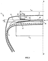
- the axial width L 41 of the first working layer 41 is equal to 234 mm.
- the axial width L 42 of the second working layer 42 is equal to 216 mm
- the layer 43 of circumferential reinforcing element has a width equal to 18 mm.
- the crown reinforcement is itself capped with a tread 5.
- a rubbery layer P is radially outwardly and in contact with the working crown ply 41.
- a layer G of rubbery mixture radially outside and in contact with the layer P of rubber mixtures comes into contact with the layer 42.
- the section G covers the end of said working layer 41 and extends beyond the axially outer end of said layer 41, while advantageously the axially outer end of the profile P does not go beyond the axially outer end of the layer 41.
- the set of profiles P and G forms a rubber layer called decoupling rubber.
- the combination of the layers of rubber mix P and G ensures in particular a decoupling between the working layer 41 and the end of the working layer 42 radially outer.
- the zone of engagement of the rubber mix profiles P and G between the two working plies 41 and 42 is defined by the thickness or more precisely the radial distance d between the end of the ply 42 and the ply 41 and by the axial width D of the rubber mix profile G between the axially inner end of said rubber mix profile G and the end of the axially narrow working crown ply 42.
- the radial distance d is equal to 3.5 mm.
- the axial distance D is equal to 20 mm, ie approximately 13.3 times the diameter ⁇ 2 of the reinforcement elements of the working ply 42, the diameter ⁇ 2 being equal to 1.5 mm.
- the two working plies 41 and 42 respectively have calenders, that is to say layers of rubbery mixture in contact with the reinforcing elements, consisting of the same rubber mix.
- the nature of the calendering may be the same for the different layers or different.
- the elastic moduli at 10% elongation of the layers of rubber mix P and G and of the "C" calendering layer of the working ply 42; respectively MP and MG and MC, are chosen such that they satisfy the following relation: MP ⁇ MG ⁇ MC.
- Such an embodiment of the tire 1 allows a reduction of the stresses of the calender layer of the working layer 42, through the layer of rubber mix G in contact with the working ply 42 to the layer of rubber mix P at contact of the working ply 41, which improves the resistance of the top architecture to the separation between the ends of the working plies 41 and 42.
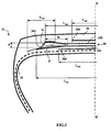
- the tire 21 still differs from that represented on the figure 1 in that it has an additional layer 243 which extends beyond the axially outer end of the layer 242 and which contacts the layer 241 to extend to the axially outer end of said layer 241.
- the axially outer end of the profile G is defined as being limited axially by the end of the layer 241.
- the layer 243 of circumferential reinforcement element has a width equal to 36 mm.
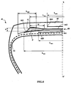
- the tire 31 differs from that shown on the figure 2 in that the additional layer 343 extends axially beyond the end of the working layer 341.
- the circumferential reinforcement element layer 343 has a width equal to 42 mm.
- Another variant embodiment of the invention relates to the case of an additional layer which extends axially beyond the end axially outside of the radially outer working layer and which remains at a distance greater than 1.5 mm from the end of the radially inner working layer.
- the end of the additional layer may be located axially between the ends of the two working layers or be located beyond the end of the axially widest working layer.
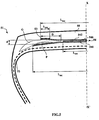
- the tire 41 differs from that shown on the figure 3 in that it comprises an additional layer 443 which is inserted between the two working layers 441 and 442.
- the layer 443 is indeed radially adjacent and internal to the layer 442; according to this embodiment of the invention, the additional layer 443 is also radially adjacent to the layer 441.
- the additional layer 443 may be at the sole contact of the working crown layer 442 or may be further is in contact only with the working crown layer 441 either radially adjacent and external to it being radially adjacent and interior thereto.
- the figure 5 illustrates an alternative embodiment of a tire 51 according to the invention which compared to the realization of the figure 1 further comprises a continuous layer 546 of circumferential reinforcing elements interposed between the working layers 541 and 542.
- This continuous layer 546 has a width L 546 equal to 196 mm, smaller than the widths of the working layers 541 and 542.
- the figure 6 illustrates yet another alternative embodiment of a tire 61 according to the invention which compared to the realization of the figure 2 has a protective layer 644 radially adjacent and external to the additional layer 643. According to this embodiment the axially inner end of the additional layer 643 is thus radially between the working layer 642 and the protective layer 644.
- This conventional tire does not have the additional layers and has a simple decoupling layer between the working layers. However, they include layers of protection and triangulation.
- the first endurance tests were carried out by equipping identical vehicles with each of the tires and by making straight-course journeys to each of the vehicles, the tires being subjected to loads greater than the nominal load to accelerate this type of test. .
- the reference vehicle comprising the usual tires is associated with a load per tire of 3600 kg at the beginning of rolling and evolves to reach a load of 4350 kg at the end of rolling.
- the vehicle comprising the tires according to the invention is associated with a load per tire of 3800 kg at the beginning of rolling and evolves to reach a load of 4800 kg at the end of rolling.
- the tests are stopped when the tire is damaged and / or no longer functions normally.
Claims (28)
- Luftreifen (1-61) mit radialer Karkassenbewehrung (2-62), der eine von mindestens zwei Arbeitsscheitelschichten (41-641, 42-642) aus nicht dehnbaren Verstärkungselementen, die sich von einer Lage zur anderen kreuzen, indem sie mit der Umfangsrichtung Winkel zwischen 10° und 45° bilden, geformte Scheitelbewehrung (4-64) enthält, die selbst radial von einem Laufstreifen (5-65) überdeckt wird, wobei der Laufstreifen über zwei Flanken mit zwei Wülsten verbunden ist, wobei mindestens zwei Arbeitsschichten (41-641, 42-642) unterschiedliche axiale Breiten haben, wobei mindestens ein erstes Profilteil P aus einer Kautschukmischung eine Arbeitsschicht (41-641) von mindestens einem Ende einer axial schmaleren zweiten Schicht (42, 642) trennt, wobei das Profilteil P radial zumindest zum Teil von der Innenseele C der axial schmaleren Arbeitsschicht (42, 642) durch ein zweites Profilteil aus Kautschukmischung G getrennt ist, wobei das erste und das zweite Profilteil aus Kautschukmischung P und G und die Innenseele C jeweils derartige Sekanten-Elastizitätsmodule unter Spannung bei 10 % Dehnung MP, MG, MC haben, dass gilt MC ≥ MG > MP, dadurch gekennzeichnet, dass der Luftreifen in jeder Schulter zusätzlich mindestens eine Schicht von Verstärkungselementen (43-643) enthält, die in der zusätzlichen Schicht parallel zueinander und in Umfangsrichtung ausgerichtet sind, dass das axial innere Ende der zusätzlichen Schicht radial dem Rand mindestens einer Arbeitsscheitelschicht (41-641, 42-642) benachbart ist, und dass mindestens ein Teil der zusätzlichen Schicht radial und/oder axial dem Rand der axial breitesten Arbeitsschicht (41-641) benachbart ist.
- Luftreifen nach Anspruch 1, dadurch gekennzeichnet, dass das axial innere Ende der zusätzlichen Schicht radial benachbart und vorzugsweise außen zum Rand der axial schmalsten Arbeitsscheitelschicht (42-642) liegt.
- Luftreifen nach einem der Ansprüche 1 oder 2, dadurch gekennzeichnet, dass das axial äußere Ende der zusätzlichen Schicht sich in einem Abstand zur Äquatorialebene des Luftreifens befindet, der geringer als der oder gleich dem Abstand ist, der von dieser Ebene das Ende der Arbeitsschicht trennt, der sie benachbart ist (41-641).
- Luftreifen nach einem der Ansprüche 1 oder 2, dadurch gekennzeichnet, dass das axial äußere Ende der zusätzlichen Schicht axial außen zum Ende der Arbeitsscheitelschicht liegt, der sie benachbart ist (41-641).
- Luftreifen nach einem der Ansprüche 1 bis 4, dadurch gekennzeichnet, dass das axial äußere Ende des ersten Profilteils P sich in einem Abstand zur Äquatorialebene des Luftreifens befindet, der geringer als der Abstand ist, der von dieser Ebene das Ende der axial breitesten Arbeitsschicht trennt (41-641).
- Luftreifen nach einem der Ansprüche 1 bis 5, dadurch gekennzeichnet, dass das axial äußere Ende des zweiten Profilteils aus Kautschukmischung G sich in einem Abstand zu dieser Ebene befindet, der mindestens gleich der halben Breite der axial schmaleren Lage von Verstärkungselementen (42-642) ist.
- Luftreifen nach einem der vorhergehenden Ansprüche, dadurch gekennzeichnet, dass das axial innere Ende des zweiten Profilteils aus Kautschukmischung G sich in einem Abstand von der Äquatorialebene befindet, der höchstens gleich dem Abstand ist, der von dieser Ebene das axial innere Ende des ersten Profilteils aus Kautschukmischung P trennt.
- Luftreifen nach einem der vorhergehenden Ansprüche, dadurch gekennzeichnet, dass die axial breiteste Arbeitsscheitelschicht (41-641) sich radial innen bezüglich der anderen Arbeitsscheitelschichten befindet.
- Luftreifen nach einem der vorhergehenden Ansprüche, dadurch gekennzeichnet, dass die axiale Breite D des Profilteils P und/oder G, die zwischen dem axial am weitesten innen liegenden Ende des Profilteils P und/oder G und dem Ende der axial schmalsten Arbeitsscheitellage (42-642) liegt, derart ist, dass gilt:

mit φ2 dem Durchmesser der Verstärkungselemente der radial äußeren Arbeitsscheitellage. - Luftreifen nach einem der vorhergehenden Ansprüche, dadurch gekennzeichnet, dass die axiale Breite D des Profilteils P und/oder G, die zwischen dem axial am weitesten innen liegenden Ende des Profilteils P und/oder G und dem axial äußeren Ende der axial schmalsten Arbeitsscheitelschicht (42-642) liegt, größer als 5 mm ist.
- Luftreifen nach einem der vorhergehenden Ansprüche, dadurch gekennzeichnet, dass die kumulierte Dicke der Profilteile P und G am axial äußeren Ende der axial schmalsten Arbeitsscheitellage (42-642) derart ist, dass der radiale Abstand d zwischen den zwei Arbeitsscheitellagen (41-641, 42-642), die durch das Profilteil P und/oder G getrennt werden, die folgende Beziehung erfüllt:

mit φ2 dem Durchmesser der Verstärkungselemente der radial äußeren Arbeitsscheitellage. - Luftreifen nach einem der vorhergehenden Ansprüche, dadurch gekennzeichnet, dass die Differenz zwischen der axialen Breite der axial breitesten Arbeitsscheitelschicht (41-641) und der axialen Breite der axial schmalsten Arbeitsscheitelschicht (42-642) zwischen 5 und 30 mm liegt.
- Luftreifen nach einem der vorhergehenden Ansprüche, dadurch gekennzeichnet, dass der von den Verstärkungselementen der Arbeitsscheitelschichten (41-641, 42-642) mit der Umfangsrichtung gebildete Winkel geringer als 30° und vorzugsweise geringer als 25° ist.
- Luftreifen nach einem der vorhergehenden Ansprüche, dadurch gekennzeichnet, dass die Arbeitsscheitelschichten (41-641, 42-642) Verstärkungselemente aufweisen, die sich von einer Lage zur anderen kreuzen und mit der Umfangsrichtung variable Winkel in axialer Richtung bilden.
- Luftreifen nach einem der vorhergehenden Ansprüche, dadurch gekennzeichnet, dass die Scheitelbewehrung radial außen durch mindestens eine zusätzliche Lage, Schutzlage genannt (244-644), von so genannten elastischen Verstärkungselementen vervollständigt wird, die bezüglich der Umfangsrichtung mit einem Winkel zwischen 10° und 45° und von gleicher Richtung wie der Winkel ausgerichtet sind, der von den nicht dehnbaren Elementen der Arbeitslage (42-642) gebildet wird, die ihr radial benachbart ist.
- Luftreifen nach einem der vorhergehenden Ansprüche, dadurch gekennzeichnet, dass die Scheitelbewehrung eine Triangulationsschicht (245-645) aufweist, die von metallischen Verstärkungselementen gebildet wird, die mit der Umfangsrichtung Winkel von mehr als 40° bilden.
- Luftreifen nach einem der vorhergehenden Ansprüche, dadurch gekennzeichnet, dass die Verstärkungselemente der Schicht von Umfangsverstärkungselementen metallische Verstärkungselemente sind.
- Luftreifen nach einem der Ansprüche 1 bis 16, dadurch gekennzeichnet, dass die Verstärkungselemente der Schicht von Umfangsverstärkungselementen textile Verstärkungselemente sind.
- Luftreifen nach einem der vorhergehenden Ansprüche, dadurch gekennzeichnet, dass die Scheitelbewehrung mindestens eine durchgehende Schicht (546) von Umfangsverstärkungselementen aufweist.
- Luftreifen nach Anspruch 19, dadurch gekennzeichnet, dass die axiale Breite mindestens einer durchgehenden Schicht (546) von Umfangsverstärkungselementen geringer als die axiale Breite der axial breitesten Arbeitsscheitelschicht (541) ist.
- Luftreifen nach Anspruch 19 oder 20, dadurch gekennzeichnet, dass mindestens eine durchgehende Schicht (546) von Umfangsverstärkungselementen radial zwischen zwei Arbeitsscheitelschichten (541, 542) angeordnet ist.
- Luftreifen nach Anspruch 21, dadurch gekennzeichnet, dass die axialen Breiten der der durchgehenden Schicht (546) von Umfangsverstärkungselementen radial benachbarten Arbeitsscheitelschichten (541, 542) größer als die axiale Breite der durchgehenden Schicht von Umfangsverstärkungselementen sind.
- Luftreifen nach einem der Ansprüche 19 bis 22, dadurch gekennzeichnet, dass die Verstärkungselemente mindestens einer durchgehenden Schicht (546) von Umfangsverstärkungselementen metallische Verstärkungselemente sind, die einen Sekantenmodul bei 0,7 % Längung zwischen 10 und 120 GPa und einen maximalen Tangentenmodul geringer als 150 GPa aufweisen.
- Luftreifen nach Anspruch 23, dadurch gekennzeichnet, dass der Sekantenmodul der Verstärkungselemente bei 0,7 % Längung geringer als 100 GPa, vorzugsweise höher als 20 GPa ist, und noch bevorzugter zwischen 30 und 90 GPa liegt.
- Luftreifen nach einem der Ansprüche 23 oder 24, dadurch gekennzeichnet, dass der maximale Tangentenmodul der Verstärkungselemente geringer als 130 GPa und vorzugsweise geringer als 120 GPa ist.
- Luftreifen nach einem der Ansprüche 19 bis 25, dadurch gekennzeichnet, dass die Verstärkungselemente mindestens einer durchgehenden Schicht (546) von Umfangsverstärkungselementen metallische Verstärkungselemente sind, die eine Zugbeanspruchungskennlinie in Abhängigkeit von der relativen Längung haben, die geringe Steigungen für die geringen Längungen und eine im Wesentlichen konstante und starke Steigung für die größeren Längungen hat.
- Luftreifen nach einem der Ansprüche 19 bis 22, dadurch gekennzeichnet, dass die Verstärkungselemente mindestens einer durchgehenden Schicht (546) von Umfangsverstärkungselementen metallische Verstärkungselemente sind, die so geschnitten werden, dass sie Abschnitte einer geringeren Länge als der Umfang der kürzesten Lage, aber größer als 0,1 Mal der Umfang haben, wobei die Schnitte zwischen Abschnitten axial zueinander versetzt sind, wobei der Zugelastizitätsmodul pro Breiteneinheit der durchgehenden Schicht von Umfangsverstärkungselementen vorzugsweise geringer als der Zugelastizitätsmodul, gemessen unter den gleichen Bedingungen, der dehnbarsten Arbeitsscheitelschicht ist.
- Luftreifen nach einem der Ansprüche 19 bis 22, dadurch gekennzeichnet, dass die Verstärkungselemente mindestens einer durchgehenden Schicht (546) von Umfangsverstärkungselementen gewellte metallische Verstärkungselemente sind, wobei das Verhältnis a/λ der Welligkeitsamplitude a zur Wellenlänge λ höchstens gleich 0,09 ist, wobei der Zugelastizitätsmodul pro Breiteneinheit der durchgehenden Schicht von Umfangsverstärkungselementen vorzugsweise geringer als der Zugelastizitätsmodul, gemessen unter den gleichen Bedingungen, der dehnbarsten Arbeitsscheitelschicht ist.
Applications Claiming Priority (2)
| Application Number | Priority Date | Filing Date | Title |
|---|---|---|---|
| FR0506766A FR2887816A1 (fr) | 2005-06-30 | 2005-06-30 | Pneumatique pour vehicules lourds |
| PCT/EP2006/063646 WO2007003550A1 (fr) | 2005-06-30 | 2006-06-28 | Pneumatique pour vehicules lourds |
Publications (2)
| Publication Number | Publication Date |
|---|---|
| EP1899178A1 EP1899178A1 (de) | 2008-03-19 |
| EP1899178B1 true EP1899178B1 (de) | 2010-08-18 |
Family
ID=35681626
Family Applications (1)
| Application Number | Title | Priority Date | Filing Date |
|---|---|---|---|
| EP06763942A Not-in-force EP1899178B1 (de) | 2005-06-30 | 2006-06-28 | Reifen für schwerfahrzeuge |
Country Status (10)
| Country | Link |
|---|---|
| US (1) | US20090272477A1 (de) |
| EP (1) | EP1899178B1 (de) |
| JP (1) | JP4902649B2 (de) |
| CN (1) | CN101213091B (de) |
| AT (1) | ATE477941T1 (de) |
| BR (1) | BRPI0612393A2 (de) |
| CA (1) | CA2611085A1 (de) |
| DE (1) | DE602006016284D1 (de) |
| FR (1) | FR2887816A1 (de) |
| WO (1) | WO2007003550A1 (de) |
Families Citing this family (7)
| Publication number | Priority date | Publication date | Assignee | Title |
|---|---|---|---|---|
| FR2887814A1 (fr) * | 2005-06-30 | 2007-01-05 | Michelin Soc Tech | Pneumatique pour vehicules lourds |
| JP5278328B2 (ja) * | 2007-10-23 | 2013-09-04 | 横浜ゴム株式会社 | 空気入りタイヤ |
| JP5694713B2 (ja) * | 2010-09-15 | 2015-04-01 | 株式会社ブリヂストン | 空気入りタイヤ |
| DE102011000703A1 (de) * | 2011-02-14 | 2012-08-16 | Continental Reifen Deutschland Gmbh | Verfahren zur Herstellung eines Fahrzeugluftreifens |
| FR3038259B1 (fr) * | 2015-07-03 | 2017-07-21 | Michelin & Cie | Pneumatique comportant trois couches de travail |
| FR3057810A1 (fr) * | 2016-10-21 | 2018-04-27 | Compagnie Generale Des Etablissements Michelin | Pneumatique a couches de travail comprenant une architecture optimisee |
| EP3746313B1 (de) * | 2018-01-30 | 2022-03-23 | Compagnie Generale Des Etablissements Michelin | Reifen mit drei arbeitsschichten |
Family Cites Families (16)
| Publication number | Priority date | Publication date | Assignee | Title |
|---|---|---|---|---|
| DE3108140A1 (de) * | 1981-03-04 | 1982-09-16 | Continental Gummi-Werke Ag, 3000 Hannover | "fahrzeugluftreifen" |
| JPS6022504A (ja) * | 1983-07-14 | 1985-02-05 | Toyo Tire & Rubber Co Ltd | 重荷重車両用ラジアルタイヤ |
| JPH1044713A (ja) * | 1996-07-30 | 1998-02-17 | Yokohama Rubber Co Ltd:The | 空気入りラジアルタイヤ |
| FR2754769B1 (fr) * | 1996-10-23 | 1998-12-11 | Michelin & Cie | Armature de sommet pour pneumatique "poids-lourds" de rapport de forme < 0,60 |
| FR2759945B1 (fr) * | 1997-02-24 | 1999-04-02 | Michelin & Cie | Pneumatique de rapport de forme h/s inferieur ou egal a 0,6 |
| FR2770457B1 (fr) * | 1997-11-05 | 1999-12-03 | Michelin & Cie | Armature de sommet de pneumatique |
| FR2774333B1 (fr) * | 1998-02-05 | 2000-03-03 | Michelin & Cie | Pneumatique a armature de sommet triangulee |
| JP4073081B2 (ja) * | 1998-05-08 | 2008-04-09 | 株式会社ブリヂストン | 空気入りラジアルタイヤ |
| DE69906103T2 (de) * | 1998-10-02 | 2003-12-18 | Technologie Michelin Clermont | Scheitelbewehrung für Radialreifen |
| EP1189769B1 (de) * | 1999-05-14 | 2008-08-20 | Société de Technologie Michelin | Verstärkungsgürtel für einen radialreifen |
| JP4612181B2 (ja) * | 2000-12-22 | 2011-01-12 | 住友ゴム工業株式会社 | 空気入りタイヤ |
| DE602004020973D1 (de) * | 2003-02-17 | 2009-06-18 | Michelin Soc Tech | Gürtelverstärkung für einen radialreifen |
| BRPI0407523A (pt) * | 2003-02-17 | 2006-02-14 | Technologie Michelin E Micheli | pneumático |
| BRPI0412723B1 (pt) * | 2003-07-18 | 2013-12-24 | Michelin Rech Tech | Pneumático com armação de carcaça radial |
| FR2887817A1 (fr) * | 2005-06-30 | 2007-01-05 | Michelin Soc Tech | Pneumatique pour vehicules lourds |
| FR2887818A1 (fr) * | 2005-06-30 | 2007-01-05 | Michelin Soc Tech | Pneumatique pour vehicules lourds |
-
2005
- 2005-06-30 FR FR0506766A patent/FR2887816A1/fr active Pending
-
2006
- 2006-06-28 BR BRPI0612393-7A patent/BRPI0612393A2/pt not_active IP Right Cessation
- 2006-06-28 US US11/922,965 patent/US20090272477A1/en not_active Abandoned
- 2006-06-28 CN CN2006800236060A patent/CN101213091B/zh not_active Expired - Fee Related
- 2006-06-28 WO PCT/EP2006/063646 patent/WO2007003550A1/fr active Application Filing
- 2006-06-28 DE DE602006016284T patent/DE602006016284D1/de active Active
- 2006-06-28 AT AT06763942T patent/ATE477941T1/de not_active IP Right Cessation
- 2006-06-28 CA CA002611085A patent/CA2611085A1/fr not_active Abandoned
- 2006-06-28 EP EP06763942A patent/EP1899178B1/de not_active Not-in-force
- 2006-06-28 JP JP2008518831A patent/JP4902649B2/ja not_active Expired - Fee Related
Also Published As
| Publication number | Publication date |
|---|---|
| CA2611085A1 (fr) | 2007-01-11 |
| US20090272477A1 (en) | 2009-11-05 |
| JP4902649B2 (ja) | 2012-03-21 |
| WO2007003550A1 (fr) | 2007-01-11 |
| CN101213091B (zh) | 2012-05-23 |
| ATE477941T1 (de) | 2010-09-15 |
| FR2887816A1 (fr) | 2007-01-05 |
| DE602006016284D1 (de) | 2010-09-30 |
| JP2009500215A (ja) | 2009-01-08 |
| CN101213091A (zh) | 2008-07-02 |
| EP1899178A1 (de) | 2008-03-19 |
| BRPI0612393A2 (pt) | 2012-10-02 |
Similar Documents
| Publication | Publication Date | Title |
|---|---|---|
| EP1899175B1 (de) | Lkw-reifen | |
| EP1648719B1 (de) | Lkw-reifen | |
| EP1648718B1 (de) | Lkw-reifen | |
| EP1899183B1 (de) | Reifen für schwerfahrzeuge | |
| EP1899176B1 (de) | Reifen für schwerfahrzeuge | |
| EP1899180B1 (de) | Reifen für schwerfahrzeuge | |
| EP1899174B1 (de) | Lkw-reifen | |
| EP1899178B1 (de) | Reifen für schwerfahrzeuge | |
| EP1899182B1 (de) | Reifen für schwerfahrzeuge | |
| EP1899179B1 (de) | Reifen für schwerfahrzeuge | |
| EP1899181B1 (de) | Reifen für schwerfahrzeuge | |
| EP1899173B1 (de) | Lkw-reifen | |
| EP1899177B1 (de) | Reifen für schwerfahrzeuge | |
| EP1899172B1 (de) | Reifen für schwerfahrzeuge |
Legal Events
| Date | Code | Title | Description |
|---|---|---|---|
| PUAI | Public reference made under article 153(3) epc to a published international application that has entered the european phase |
Free format text: ORIGINAL CODE: 0009012 |
|
| 17P | Request for examination filed |
Effective date: 20080130 |
|
| AK | Designated contracting states |
Kind code of ref document: A1 Designated state(s): AT BE BG CH CY CZ DE DK EE ES FI FR GB GR HU IE IS IT LI LT LU LV MC NL PL PT RO SE SI SK TR |
|
| DAX | Request for extension of the european patent (deleted) | ||
| DAX | Request for extension of the european patent (deleted) | ||
| 17Q | First examination report despatched |
Effective date: 20090120 |
|
| GRAP | Despatch of communication of intention to grant a patent |
Free format text: ORIGINAL CODE: EPIDOSNIGR1 |
|
| GRAS | Grant fee paid |
Free format text: ORIGINAL CODE: EPIDOSNIGR3 |
|
| GRAA | (expected) grant |
Free format text: ORIGINAL CODE: 0009210 |
|
| AK | Designated contracting states |
Kind code of ref document: B1 Designated state(s): AT BE BG CH CY CZ DE DK EE ES FI FR GB GR HU IE IS IT LI LT LU LV MC NL PL PT RO SE SI SK TR |
|
| REG | Reference to a national code |
Ref country code: GB Ref legal event code: FG4D Free format text: NOT ENGLISH |
|
| REG | Reference to a national code |
Ref country code: CH Ref legal event code: EP |
|
| REG | Reference to a national code |
Ref country code: IE Ref legal event code: FG4D Free format text: LANGUAGE OF EP DOCUMENT: FRENCH |
|
| REF | Corresponds to: |
Ref document number: 602006016284 Country of ref document: DE Date of ref document: 20100930 Kind code of ref document: P |
|
| REG | Reference to a national code |
Ref country code: NL Ref legal event code: T3 |
|
| LTIE | Lt: invalidation of european patent or patent extension |
Effective date: 20100818 |
|
| PG25 | Lapsed in a contracting state [announced via postgrant information from national office to epo] |
Ref country code: AT Free format text: LAPSE BECAUSE OF FAILURE TO SUBMIT A TRANSLATION OF THE DESCRIPTION OR TO PAY THE FEE WITHIN THE PRESCRIBED TIME-LIMIT Effective date: 20100818 Ref country code: FI Free format text: LAPSE BECAUSE OF FAILURE TO SUBMIT A TRANSLATION OF THE DESCRIPTION OR TO PAY THE FEE WITHIN THE PRESCRIBED TIME-LIMIT Effective date: 20100818 Ref country code: LT Free format text: LAPSE BECAUSE OF FAILURE TO SUBMIT A TRANSLATION OF THE DESCRIPTION OR TO PAY THE FEE WITHIN THE PRESCRIBED TIME-LIMIT Effective date: 20100818 |
|
| PG25 | Lapsed in a contracting state [announced via postgrant information from national office to epo] |
Ref country code: SI Free format text: LAPSE BECAUSE OF FAILURE TO SUBMIT A TRANSLATION OF THE DESCRIPTION OR TO PAY THE FEE WITHIN THE PRESCRIBED TIME-LIMIT Effective date: 20100818 Ref country code: IS Free format text: LAPSE BECAUSE OF FAILURE TO SUBMIT A TRANSLATION OF THE DESCRIPTION OR TO PAY THE FEE WITHIN THE PRESCRIBED TIME-LIMIT Effective date: 20101218 Ref country code: CY Free format text: LAPSE BECAUSE OF FAILURE TO SUBMIT A TRANSLATION OF THE DESCRIPTION OR TO PAY THE FEE WITHIN THE PRESCRIBED TIME-LIMIT Effective date: 20100818 Ref country code: PT Free format text: LAPSE BECAUSE OF FAILURE TO SUBMIT A TRANSLATION OF THE DESCRIPTION OR TO PAY THE FEE WITHIN THE PRESCRIBED TIME-LIMIT Effective date: 20101220 Ref country code: PL Free format text: LAPSE BECAUSE OF FAILURE TO SUBMIT A TRANSLATION OF THE DESCRIPTION OR TO PAY THE FEE WITHIN THE PRESCRIBED TIME-LIMIT Effective date: 20100818 Ref country code: BG Free format text: LAPSE BECAUSE OF FAILURE TO SUBMIT A TRANSLATION OF THE DESCRIPTION OR TO PAY THE FEE WITHIN THE PRESCRIBED TIME-LIMIT Effective date: 20101118 |
|
| REG | Reference to a national code |
Ref country code: IE Ref legal event code: FD4D |
|
| PG25 | Lapsed in a contracting state [announced via postgrant information from national office to epo] |
Ref country code: LV Free format text: LAPSE BECAUSE OF FAILURE TO SUBMIT A TRANSLATION OF THE DESCRIPTION OR TO PAY THE FEE WITHIN THE PRESCRIBED TIME-LIMIT Effective date: 20100818 Ref country code: GR Free format text: LAPSE BECAUSE OF FAILURE TO SUBMIT A TRANSLATION OF THE DESCRIPTION OR TO PAY THE FEE WITHIN THE PRESCRIBED TIME-LIMIT Effective date: 20101119 Ref country code: SE Free format text: LAPSE BECAUSE OF FAILURE TO SUBMIT A TRANSLATION OF THE DESCRIPTION OR TO PAY THE FEE WITHIN THE PRESCRIBED TIME-LIMIT Effective date: 20100818 |
|
| PG25 | Lapsed in a contracting state [announced via postgrant information from national office to epo] |
Ref country code: IE Free format text: LAPSE BECAUSE OF FAILURE TO SUBMIT A TRANSLATION OF THE DESCRIPTION OR TO PAY THE FEE WITHIN THE PRESCRIBED TIME-LIMIT Effective date: 20100818 Ref country code: DK Free format text: LAPSE BECAUSE OF FAILURE TO SUBMIT A TRANSLATION OF THE DESCRIPTION OR TO PAY THE FEE WITHIN THE PRESCRIBED TIME-LIMIT Effective date: 20100818 |
|
| PG25 | Lapsed in a contracting state [announced via postgrant information from national office to epo] |
Ref country code: RO Free format text: LAPSE BECAUSE OF FAILURE TO SUBMIT A TRANSLATION OF THE DESCRIPTION OR TO PAY THE FEE WITHIN THE PRESCRIBED TIME-LIMIT Effective date: 20100818 Ref country code: EE Free format text: LAPSE BECAUSE OF FAILURE TO SUBMIT A TRANSLATION OF THE DESCRIPTION OR TO PAY THE FEE WITHIN THE PRESCRIBED TIME-LIMIT Effective date: 20100818 Ref country code: CZ Free format text: LAPSE BECAUSE OF FAILURE TO SUBMIT A TRANSLATION OF THE DESCRIPTION OR TO PAY THE FEE WITHIN THE PRESCRIBED TIME-LIMIT Effective date: 20100818 Ref country code: SK Free format text: LAPSE BECAUSE OF FAILURE TO SUBMIT A TRANSLATION OF THE DESCRIPTION OR TO PAY THE FEE WITHIN THE PRESCRIBED TIME-LIMIT Effective date: 20100818 Ref country code: IT Free format text: LAPSE BECAUSE OF FAILURE TO SUBMIT A TRANSLATION OF THE DESCRIPTION OR TO PAY THE FEE WITHIN THE PRESCRIBED TIME-LIMIT Effective date: 20100818 |
|
| PLBE | No opposition filed within time limit |
Free format text: ORIGINAL CODE: 0009261 |
|
| STAA | Information on the status of an ep patent application or granted ep patent |
Free format text: STATUS: NO OPPOSITION FILED WITHIN TIME LIMIT |
|
| PG25 | Lapsed in a contracting state [announced via postgrant information from national office to epo] |
Ref country code: ES Free format text: LAPSE BECAUSE OF FAILURE TO SUBMIT A TRANSLATION OF THE DESCRIPTION OR TO PAY THE FEE WITHIN THE PRESCRIBED TIME-LIMIT Effective date: 20101129 |
|
| 26N | No opposition filed |
Effective date: 20110519 |
|
| REG | Reference to a national code |
Ref country code: DE Ref legal event code: R097 Ref document number: 602006016284 Country of ref document: DE Effective date: 20110519 |
|
| BERE | Be: lapsed |
Owner name: MICHELIN RECHERCHE ET TECHNIQUE S.A. Effective date: 20110630 Owner name: SOC. DE TECHNOLOGIE MICHELIN Effective date: 20110630 |
|
| REG | Reference to a national code |
Ref country code: CH Ref legal event code: PL |
|
| GBPC | Gb: european patent ceased through non-payment of renewal fee |
Effective date: 20110628 |
|
| PG25 | Lapsed in a contracting state [announced via postgrant information from national office to epo] |
Ref country code: BE Free format text: LAPSE BECAUSE OF NON-PAYMENT OF DUE FEES Effective date: 20110630 |
|
| PG25 | Lapsed in a contracting state [announced via postgrant information from national office to epo] |
Ref country code: CH Free format text: LAPSE BECAUSE OF NON-PAYMENT OF DUE FEES Effective date: 20110630 Ref country code: LI Free format text: LAPSE BECAUSE OF NON-PAYMENT OF DUE FEES Effective date: 20110630 |
|
| PG25 | Lapsed in a contracting state [announced via postgrant information from national office to epo] |
Ref country code: GB Free format text: LAPSE BECAUSE OF NON-PAYMENT OF DUE FEES Effective date: 20110628 |
|
| PG25 | Lapsed in a contracting state [announced via postgrant information from national office to epo] |
Ref country code: MC Free format text: LAPSE BECAUSE OF NON-PAYMENT OF DUE FEES Effective date: 20110630 |
|
| PG25 | Lapsed in a contracting state [announced via postgrant information from national office to epo] |
Ref country code: LU Free format text: LAPSE BECAUSE OF NON-PAYMENT OF DUE FEES Effective date: 20110628 |
|
| PG25 | Lapsed in a contracting state [announced via postgrant information from national office to epo] |
Ref country code: TR Free format text: LAPSE BECAUSE OF FAILURE TO SUBMIT A TRANSLATION OF THE DESCRIPTION OR TO PAY THE FEE WITHIN THE PRESCRIBED TIME-LIMIT Effective date: 20100818 |
|
| PG25 | Lapsed in a contracting state [announced via postgrant information from national office to epo] |
Ref country code: HU Free format text: LAPSE BECAUSE OF FAILURE TO SUBMIT A TRANSLATION OF THE DESCRIPTION OR TO PAY THE FEE WITHIN THE PRESCRIBED TIME-LIMIT Effective date: 20100818 |
|
| REG | Reference to a national code |
Ref country code: FR Ref legal event code: PLFP Year of fee payment: 11 |
|
| PGFP | Annual fee paid to national office [announced via postgrant information from national office to epo] |
Ref country code: DE Payment date: 20160621 Year of fee payment: 11 |
|
| PGFP | Annual fee paid to national office [announced via postgrant information from national office to epo] |
Ref country code: FR Payment date: 20160627 Year of fee payment: 11 Ref country code: NL Payment date: 20160620 Year of fee payment: 11 |
|
| REG | Reference to a national code |
Ref country code: DE Ref legal event code: R119 Ref document number: 602006016284 Country of ref document: DE |
|
| REG | Reference to a national code |
Ref country code: NL Ref legal event code: MM Effective date: 20170701 |
|
| PG25 | Lapsed in a contracting state [announced via postgrant information from national office to epo] |
Ref country code: NL Free format text: LAPSE BECAUSE OF NON-PAYMENT OF DUE FEES Effective date: 20170701 |
|
| REG | Reference to a national code |
Ref country code: FR Ref legal event code: ST Effective date: 20180228 |
|
| PG25 | Lapsed in a contracting state [announced via postgrant information from national office to epo] |
Ref country code: DE Free format text: LAPSE BECAUSE OF NON-PAYMENT OF DUE FEES Effective date: 20180103 |
|
| PG25 | Lapsed in a contracting state [announced via postgrant information from national office to epo] |
Ref country code: FR Free format text: LAPSE BECAUSE OF NON-PAYMENT OF DUE FEES Effective date: 20170630 |