EP1899181B1 - Reifen für schwerfahrzeuge - Google Patents
Reifen für schwerfahrzeuge Download PDFInfo
- Publication number
- EP1899181B1 EP1899181B1 EP06763952A EP06763952A EP1899181B1 EP 1899181 B1 EP1899181 B1 EP 1899181B1 EP 06763952 A EP06763952 A EP 06763952A EP 06763952 A EP06763952 A EP 06763952A EP 1899181 B1 EP1899181 B1 EP 1899181B1
- Authority
- EP
- European Patent Office
- Prior art keywords
- layer
- axially
- reinforcement elements
- tire according
- working
- Prior art date
- Legal status (The legal status is an assumption and is not a legal conclusion. Google has not performed a legal analysis and makes no representation as to the accuracy of the status listed.)
- Not-in-force
Links
Images


Classifications
-
- B—PERFORMING OPERATIONS; TRANSPORTING
- B60—VEHICLES IN GENERAL
- B60C—VEHICLE TYRES; TYRE INFLATION; TYRE CHANGING; CONNECTING VALVES TO INFLATABLE ELASTIC BODIES IN GENERAL; DEVICES OR ARRANGEMENTS RELATED TO TYRES
- B60C9/00—Reinforcements or ply arrangement of pneumatic tyres
- B60C9/18—Structure or arrangement of belts or breakers, crown-reinforcing or cushioning layers
- B60C9/20—Structure or arrangement of belts or breakers, crown-reinforcing or cushioning layers built-up from rubberised plies each having all cords arranged substantially parallel
- B60C9/22—Structure or arrangement of belts or breakers, crown-reinforcing or cushioning layers built-up from rubberised plies each having all cords arranged substantially parallel the plies being arranged with all cords disposed along the circumference of the tyre
-
- B—PERFORMING OPERATIONS; TRANSPORTING
- B60—VEHICLES IN GENERAL
- B60C—VEHICLE TYRES; TYRE INFLATION; TYRE CHANGING; CONNECTING VALVES TO INFLATABLE ELASTIC BODIES IN GENERAL; DEVICES OR ARRANGEMENTS RELATED TO TYRES
- B60C9/00—Reinforcements or ply arrangement of pneumatic tyres
- B60C9/18—Structure or arrangement of belts or breakers, crown-reinforcing or cushioning layers
- B60C9/20—Structure or arrangement of belts or breakers, crown-reinforcing or cushioning layers built-up from rubberised plies each having all cords arranged substantially parallel
- B60C9/2003—Structure or arrangement of belts or breakers, crown-reinforcing or cushioning layers built-up from rubberised plies each having all cords arranged substantially parallel characterised by the materials of the belt cords
- B60C9/2006—Structure or arrangement of belts or breakers, crown-reinforcing or cushioning layers built-up from rubberised plies each having all cords arranged substantially parallel characterised by the materials of the belt cords consisting of steel cord plies only
-
- B—PERFORMING OPERATIONS; TRANSPORTING
- B60—VEHICLES IN GENERAL
- B60C—VEHICLE TYRES; TYRE INFLATION; TYRE CHANGING; CONNECTING VALVES TO INFLATABLE ELASTIC BODIES IN GENERAL; DEVICES OR ARRANGEMENTS RELATED TO TYRES
- B60C9/00—Reinforcements or ply arrangement of pneumatic tyres
- B60C9/18—Structure or arrangement of belts or breakers, crown-reinforcing or cushioning layers
- B60C9/1835—Rubber strips or cushions at the belt edges
- B60C2009/1842—Width or thickness of the strips or cushions
Definitions
- the present invention relates to a tire with radial carcass reinforcement and more particularly to a tire intended to equip vehicles carrying heavy loads and traveling at a high speed, such as, for example, trucks, tractors, trailers or road buses, of the type described by FR-A-2 501 126 .
- the reinforcing reinforcement or reinforcement of tires and in particular tires of vehicles of the truck-type is at present - and most often - constituted by stacking one or more plies conventionally referred to as "carcass plies", " tablecloths ", etc.
- This method of designating reinforcing reinforcements comes from the manufacturing process, consisting in producing a series of semi-finished products in the form of plies, provided with wire reinforcements, often longitudinal, which are subsequently assembled or stacked in order to make a rough draft. pneumatic. Tablecloths are made flat, with large dimensions, and are subsequently cut according to the dimensions of a given product.
- the assembly of the plies is also made, initially, substantially flat.
- the blank thus produced is then shaped to adopt the typical toroidal profile of the tires.
- the so-called "finished” semi-finished products are then applied to the blank to obtain a product ready for vulcanization.
- Such a type of "conventional" process involves, in particular for the manufacturing phase of the blank of the tire, the use of an anchoring element (generally a bead wire), used to carry out the anchoring or the maintenance of the carcass reinforcement in the area of the beads of the tire.
- an anchoring element generally a bead wire
- a portion of all the plies constituting the carcass reinforcement is turned around around a bead wire disposed in the bead of the tire. In this way, an anchoring of the carcass reinforcement in the bead is created.
- the tires described in this document do not have the "traditional" reversal of carcass ply around a rod.
- This type of anchorage is replaced by an arrangement in which is disposed adjacent to said sidewall reinforcing structure circumferential son, all being embedded in a rubber mix anchoring or bonding.
- anchoring zone can mean as much the “traditional” reversal of carcass ply around a rod of a conventional method, that the assembly formed by the circumferential reinforcing elements, the rubber mix and adjacent flank reinforcement portions of a low zone made with a method with application to a toroidal core.
- the carcass reinforcement is anchored on both sides in the bead zone and is radially surmounted by a crown reinforcement consisting of at least two superposed layers. and formed of parallel wires or cables in each layer. It may also comprise a layer of low extensibility wires or metal cables forming with the circumferential direction an angle of between 45 ° and 90 °, this so-called triangulation ply being radially located between the carcass reinforcement and the first ply of plywood. so-called working top, formed of parallel wires or cables having angles at most equal to 45 ° in absolute value.
- the triangulation ply forms with at least said working ply a triangulated reinforcement, which presents, under the different stresses it undergoes, few deformations, the triangulation ply having the essential role of taking up the transverse compression forces of which the object all the reinforcing elements in the area of the crown of the tire.
- the crown reinforcement comprises at least one working layer; when said crown reinforcement comprises at least two working layers, these are formed of inextensible metallic reinforcement elements parallel to each other in each layer and crossed from one layer to the next, making angles with the circumferential direction between 10 ° and 45 °.
- Said working layers, forming the working armature can still be covered with at least one so-called protective layer and formed of advantageously metallic and extensible reinforcing elements, called elastic elements.
- Cables are said to be inextensible when said cables have under tensile force equal to 10% of the breaking force a relative elongation of at most 0.2%.
- Cables are said to be elastic when said cables have under a tensile force equal to the breaking load a relative elongation of at least 4%.
- the circumferential direction of the tire is the direction corresponding to the periphery of the tire and defined by the rolling direction of the tire.
- the transverse or axial direction of the tire is parallel to the axis of rotation of the tire.
- the radial direction is a direction intersecting the axis of rotation of the tire and perpendicular to it.
- the axis of rotation of the tire is the axis around which it rotates under normal use.
- a radial or meridian plane is a plane which contains the axis of rotation of the tire.
- the circumferential median plane is a plane perpendicular to the axis of rotation of the tire and which divides the tire into two halves.
- the patent FR 1 389 428 to improve the degradation resistance of the rubber compounds in the vicinity of the crown reinforcement edges, recommends the use, in combination with a low hysteresis tread, of a rubber profile covering at least the sides and the marginal edges of the crown reinforcement and consisting of a rubber mixture with low hysteresis.
- the patent FR 2,222,232 to avoid separations between crown reinforcing plies teaches to coat the ends of the frame in a rubber mat, whose Shore A hardness is different from that of the tread overlying said frame, and greater the Shore A hardness of the rubber mix profile disposed between the edges of crown reinforcement plies and carcass reinforcement.
- the French request FR 2 728 510 proposes, on the one hand, between the carcass reinforcement and the crown reinforcement working ply, radially closest to the axis of rotation, an axially continuous ply formed of inextensible metallic ropes making with the direction circumferential an angle of at least 60 °, and whose axial width is at least equal to the axial width of the shortest working crown ply, and secondly between the two working crown plies an additional ply formed of metal elements, oriented substantially parallel to the circumferential direction.
- French demand WO 99/24269 proposes, on both sides of the equatorial plane and in the immediate axial extension of the additional ply of reinforcing elements substantially parallel to the circumferential direction, to couple, over a certain axial distance, the two working crown plies formed reinforcing elements crossed from one ply to the next and then decoupling them with rubber mixing profiles at least over the remainder of the width common to said two working plies.
- An object of the invention is to provide tires for vehicles "heavy-weight" whose endurance performance is further improved over conventional tires.
- a radial carcass reinforcement tire comprising a crown reinforcement formed of at least two working crown layers of inextensible reinforcing elements, crossed from one sheet to the other by making with the circumferential direction of the angles between 10 ° and 45 °, at least one protective layer being radially outside the working crown layers, itself capped radially with a tread, said tread being connected to two beads by means of two flanks, said tire additionally comprising in each shoulder at least one layer of circumferentially oriented reinforcing elements having a corrugation, the axially inner end of said additional layer being radially adjacent and external to the radially outermost working layer and said axially inner end of the additional layer being radially adjacent and interior at least part of the protective layer.
- the reinforcing elements of the additional layer have a wavelength ripple ⁇ of between 10 and 50 mm.
- the reinforcing elements of the additional layer have a ripple amplitude of between 2 and 10 mm.
- the protective layer is axially narrower than the working layer which is radially adjacent thereto and the axially inner end of the additional layer is radially adjacent and interior to the edge of the protective layer.
- the protective layer may be axially wider than the working layer which is radially adjacent thereto and according to some embodiments the protective layer may be axially wider than all the working layers.
- a protective layer is a layer of so-called elastic reinforcing elements, oriented with respect to the circumferential direction with an angle of between 10 ° and 45 ° and in the same direction as the angle formed by the inextensible elements of the working layer which is radially adjacent thereto.
- Circumferentially oriented reinforcing elements having a corrugation are reinforcing elements which have a main orientation forming with the circumferential direction angles in the range + 2.5 °, - 2.5 ° around 0 °, and undulate around this main orientation.
- the axial widths of the layers of reinforcing elements or axial positions of the ends of said layers are measured on a cross section of a tire, the tire therefore being in an uninflated state.
- the additional layer is placed so that its axially inner end is radially interposed between the radially outer working crown layer and the edge of the protective layer and therefore also radially external to the top layer. working radially the outermost.
- the additional layer and the protective layer are radially adjacent over an axial width greater than or equal to 10 mm.
- Such an action can possibly be on the one hand linked to a local recovery of the forces, initially supported by the working layers, by the additional layer due to its main orientation in a circumferential direction and, on the other hand, the consequence of a reinforcement of the rubber calendering masses between the reinforcement elements of said working layer by the reinforcement elements of the additional layer due to the corrugation of said reinforcement elements of the additional layer.
- This effect on the forces and on the calendering rubber masses is further reinforced by the presence of a protective layer which at least covers the axially inner end of the additional layer.
- a layer P of cohesive rubbery mixtures is disposed between at least a portion of the working crown layers.
- the layer P thus defined leads to a decoupling of the working crown layers contributing in itself to the improvement of the endurance of the tire.
- Coupled plies means plies whose respective reinforcing elements are radially separated by at most 1.5 mm, said rubber thickness being measured radially between the respectively upper and lower generatrices of said reinforcing elements.
- a first embodiment of the invention provides that the axially outer end of the additional layer is located at a distance from the equatorial plane of the tire less than or equal to the distance separating from said plane the end of the working layer to which it is adjacent. According to this embodiment of the invention, the axially outer end of the additional layer is therefore axially inner to the end of at least the working layer adjacent to said additional layer.
- a second embodiment of the invention provides that the axially outer end of said additional layer is axially external to the edge of the working crown layer to which it is adjacent.
- an advantageous embodiment of the invention provides that the distance between said additional layer and the end of the axially widest working crown layer. is greater than 1.5 mm and preferably between 2 and 12 mm.
- the ends of the reinforcing elements of the axially widest working layer are not stressed because of the excessive proximity of the reinforcement elements of the additional layer.
- the reinforcing elements of the additional layer advantageously do not penetrate a circle of radius equal to 1.5 mm centered on the end of the reinforcing elements of the axially widest working layer.
- the layer P defined above will be able to contribute to ensuring a minimum distance greater than 1.5 mm between the additional layer and the end of the axially widest working crown layer.
- the layer P of rubber mixes then advantageously acts as a decoupling layer between the axially widest working layer and the additional layer.
- the axially outer end of the layer P can then advantageously be axially external to the end of the axially widest working crown layer.
- At least two working layers having different axial widths at least a portion of the additional layer is radially and / or axially adjacent the edge of the axially widest working layer.
- the additional layer is only adjacent to the axially widest working layer, or the additional layer is adjacent to two working layers.
- the axially outer end of the layer P is then advantageously located at a distance from the equatorial plane of the tire less than the distance separating from said plane the end of the ply of axially widest reinforcing elements and preferably said end is axially between the ends of the axially narrower and wider working crown layers.
- the axial width D of the section P between the axially innermost end of the section P and the end of the axially shallower working crown ply is such that: 3. ⁇ ⁇ 2 ⁇ D ⁇ 20. ⁇ ⁇ 2 with ⁇ 2 , the diameter of the reinforcement elements of the axially the least wide working crown ply.
- Such a relationship defines a zone of engagement between the P profile of rubber mixes and the axially least large working ply.
- Such an engagement below a value equal to three times the diameter of the reinforcing elements of the radially outer working ply may not be sufficient to obtain a decoupling of the working plies in particular to obtain an attenuation of the stresses at the end of the ply. working ply axially the least wide.
- a value of this engagement greater than twenty times the diameter of the reinforcing elements of the axially narrower working ply can lead to an excessive reduction in the rigidity of the crown reinforcement of the tire.
- the axial width D of the profile P between the axially innermost end of the profile P and the axially outer end of the axially least wide working crown layer is greater than 5 mm.
- the invention further preferably provides that the thickness of the profile P, at the axially outer end of the axially shallower working crown ply, has a thickness such that the radial distance d between the two working crown plies , separated by the profile P, verifies the relation: 3 / 5. ⁇ ⁇ 2 ⁇ d ⁇ 5. ⁇ ⁇ 2 with ⁇ 2 , the diameter of the reinforcement elements of the axially the least wide working crown ply.
- the distance d is measured from cable to cable, that is to say between the cable of a first working ply and the cable of a second ply of work.
- this distance d includes the thickness of the profile P and the respective thicknesses of the rubber calendering mixtures, radially external to the cables of the working ply. radially inner and radially inner to the cables of the radially outer working ply.
- the various thickness measurements are made on a cross section of a tire, the tire therefore being in a non-inflated state.
- the axially widest working crown layer is radially inside the other working crown layers.
- the difference between the axial width of the axially widest working crown layer and the axial width of the axially least wide working crown layer is between 5 and 30 mm.
- the angle formed with the circumferential direction by the reinforcement elements of the working crown layers is less than 30 ° and preferably less than 25 °.
- the working crown layers comprise reinforcing elements, crossed from one ply to the other, making with the circumferential direction variable angles in the axial direction, said angles being greater on the axially outer edges of the reinforcing element layers with respect to the angles of said elements measured at the circumferential mid-plane.
- the crown reinforcement can be further completed, for example radially between the carcass reinforcement and the radially innermost working layer, by a triangulation layer consisting of inextensible reinforcing elements making, with the circumferential direction, an angle greater than 40 ° and preferably in the same direction as that of the angle formed by the reinforcing elements of the layer radially closest to the carcass reinforcement.
- the reinforcing elements of the additional layer are metal reinforcing elements.
- the reinforcing elements of the additional layer are textile reinforcing elements.
- the crown reinforcement of the tire further comprises at least one continuous layer of circumferential reinforcement elements whose axial width is preferably less than the axial width of the crown layer of the tire. axially the widest work.
- the axial widths of the continuous layers of reinforcing elements are measured on a cross section of a tire, the tire being in an uninflated state.
- the presence in the tire according to the invention of at least one continuous layer of circumferential reinforcing elements can make it possible to contribute to obtaining quasi-infinite axial curvature radii of the various reinforcement layers in a zone centered on the plane circumferential median, which contributes to the endurance performance of the tire.
- the reinforcing elements of at least one continuous layer of circumferential reinforcing elements are metal reinforcing elements having a secant modulus at 0.7% elongation between 10 and 120 GPa and a maximum tangent modulus less than 150 GPa.
- the secant modulus of the reinforcing elements at 0.7% elongation is less than 100 GPa and greater than 20 GPa, preferably between 30 and 90 GPa and more preferably less than 80 GPa.
- the maximum tangent modulus of the reinforcing elements is less than 130 GPa and more preferably less than 120 GPa.
- the modules expressed above are measured on a tensile stress curve as a function of the elongation determined with a prestressing of 20 MPa reduced to the metal section of the reinforcing element, the tensile stress corresponding to a measured voltage brought back to the metal section of the reinforcing element.
- the modules of the same reinforcing elements can be measured on a tensile stress curve as a function of the elongation determined with a preload of 10 MPa reduced to the overall section of the reinforcing element, the tensile stress corresponding to a measured tension. brought back to the overall section of the reinforcing element.
- the overall section of the reinforcing element is the section of a composite element made of metal and rubber, the latter having in particular penetrated the reinforcing element during the baking phase of the tire.
- the reinforcing elements of at least one layer of circumferential reinforcing elements are metal reinforcing elements having a secant modulus at 0.7% of elongation included between 5 and 60 GPa and a maximum tangent modulus less than 75 GPa.
- the secant modulus of the reinforcing elements at 0.7% elongation is less than 50 GPa and greater than 10 GPa, preferably between 15 and 45 GPa and more preferably less than 40 GPa.
- the maximum tangent modulus of the reinforcing elements is less than 65 GPa and more preferably less than 60 GPa.
- the reinforcing elements of at least one continuous layer of circumferential reinforcing elements are metal reinforcing elements having a stress-strain curve as a function of the relative elongation having small slopes for the weak ones. elongations and a substantially constant and strong slope for the higher elongations.
- Such reinforcing elements of the continuous layer of circumferential reinforcing elements are usually referred to as "bi-module" elements.
- the substantially constant and strong slope appears from a relative elongation of between 0.1% and 0.5%.
- Reinforcing elements that are more particularly suitable for producing at least one continuous layer of circumferential reinforcing elements according to the invention are, for example, assemblies of formula 21.23, the construction of which is 3x (0.26 + 6x0.23). 4.4 / 6.6 SS; this strand cable consists of 21 elementary wires of formula 3 x (1 + 6), with 3 twisted strands each consisting of 7 wires, a wire forming a central core of diameter equal to 26/100 mm and 6 coiled wires of diameter equal to 23/100 mm.
- Such a cable has a secant module at 0.7% equal to 45 GPa and a maximum tangent modulus equal to 98 GPa, measured on a tensile stress curve as a function of the elongation determined with a preload of 20 MPa brought back to the section. of the reinforcing element, the tensile stress corresponding to a measured voltage brought back to the metal section of the reinforcing element.
- this cable of formula 21.23 On a tensile stress curve as a function of the elongation determined with a preload of 10 MPa brought back to the overall section of the reinforcing element, the tensile stress corresponding to a measured tension brought back to the overall section of the element of reinforcement, this cable of formula 21.23 has a secant module at 0.7% equal to 23 GPa and a maximum tangent modulus equal to 49 GPa.
- reinforcement elements is an assembly of formula 21.28, whose construction is 3x (0.32 + 6x0.28) 6.2 / 9.3 SS.
- This cable has a secant module at 0.7% equal to 56 GPa and a maximum tangent modulus equal to 102 GPa, measured on a tensile stress curve as a function of the elongation determined with a preload of 20 MPa brought to the cross section.
- metal of the reinforcing element the tensile stress corresponding to a measured voltage brought back to the metal section of the reinforcing element.
- this cable of formula 21.28 On a tensile stress curve as a function of the elongation determined with a preload of 10 MPa brought back to the overall section of the reinforcing element, the tensile stress corresponding to a measured tension brought back to the overall section of the element of reinforcement, this cable of formula 21.28 has a secant module at 0.7% equal to 27 GPa and a maximum tangent modulus equal to 49 GPa.
- the circumferential reinforcing elements of a continuous layer may be formed of metal elements that are inextensible and cut so as to form sections of length much shorter than the circumference of the least long layer. , but preferentially greater than 0.1 times said circumference, the cuts between sections being axially offset with respect to each other. More preferably, the tensile modulus of elasticity per unit width of the continuous layer of circumferential reinforcing elements is smaller than the modulus of tensile elasticity, measured under the same conditions, of the working crown layer. the most extensible.
- Such an embodiment makes it possible to confer, in a simple manner, on the continuous layer of circumferential reinforcing elements a module which can easily be adjusted (by the choice of intervals between sections of the same row), but in all cases more weak that the modulus of the layer consisting of the same metal elements but continuous, the modulus of the continuous layer of circumferential reinforcing elements being measured on a vulcanized layer of cut elements, taken from the tire.
- the circumferential reinforcing elements of a continuous layer are corrugated metal elements, the ratio a / ⁇ of the amplitude of waviness at the wavelength being at most equal to 0.09.
- the tensile modulus of elasticity per unit width of the continuous layer of circumferential reinforcing elements is smaller than the tensile modulus of elasticity, measured under the same conditions, of the working crown layer.
- the metal elements are preferably steel cables.
- At least one continuous layer of circumferential reinforcing elements is arranged radially between two working crown layers.
- the continuous layer of circumferential reinforcing elements makes it possible to limit more significantly the compression of the reinforcement elements of the carcass reinforcement than a similar layer placed radially on the outside. other layers of work top. It is preferably radially separated from the carcass reinforcement by at least one working layer so as to limit the stresses of said reinforcing elements and do not strain them too much.
- the axial widths of the working crown layers radially adjacent to the layer of circumferential reinforcing elements are greater than the axial width of said layer of circumferential reinforcing elements.
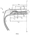
- the axial width L 41 of the first working layer 41 is equal to 226 mm.
- the axial width L 42 of the second working layer 42 is equal to 206 mm.
- the axial width L 44 of the protective layer 43 is equal to 205 mm.
- the additional layer 43 has a width equal to 53 mm.
- the crown reinforcement is itself capped with a tread 5.
- a rubbery layer P radially between and in contact with the working crown layers 41 and 42, called the decoupling rubber, covers the end of said working layer 41 and extends beyond the axially outer end of said layer 41.
- the layer P rubbery mixture ensures in particular a decoupling between the working layer 41 and the end of the working layer 42 radially outer.
- the zone of engagement of the layer P between the two working layer 41 and 42 is defined by its thickness or more precisely the radial distance d between the end of the layer 42 and the layer 41 and by its axial width D between the axially inner end of said P layer and the end of the radially outer working crown layer.
- the radial distance d is 3.5 mm.
- the axial distance D is equal to 20 mm, ie approximately 13.3 times the diameter ⁇ 2 of the reinforcement elements of the working ply 42, the diameter ⁇ 2 being equal to 1.5 mm.
- This representation of the figure 1 corresponds to an embodiment in which the axially outer end of the working layer 41 is maintained at a distance greater than 1.5 mm from the additional layer 43.
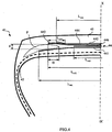
- the tire 21 differs from that shown on the figure 1 on the one hand, in that it further comprises a layer of complementary reinforcing elements 245, called triangulation, of width substantially equal to 200 mm formed of 9x28 inextensible metal cables.
- the reinforcing elements of this layer 245 form an angle of approximately 45 ° with the circumferential direction and are oriented in the same direction as the reinforcing elements of the working layer 241.
- This layer 245 makes it possible in particular to contribute to the recovery of transverse compression forces which is the object of all the reinforcing elements in the area of the crown of the tire.
- the tire 21 still differs from that represented on the figure 1 in that it has an additional layer 243 which extends beyond the axially outer end of the layer 242 and which contacts the layer 241 to extend to the axially outer end of said layer 241.
- the axially outer end of the profile P is defined as being limited axially by the end of the layer 241.
- the layer 243 of circumferential reinforcement element has a width equal to 65 mm.
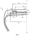
- the tire 31 differs from that shown on the figure 2 in that the additional layer 343 extends axially beyond the end of the working layer 341.
- the circumferential reinforcement element layer 343 has a width equal to 75 mm.
- the tire 41 differs from that shown on the figure 1 in that it further comprises a continuous layer 446 of circumferential reinforcing elements interposed between the working layers 441 and 442.
- This continuous layer 446 has a width L 446 equal to 185 mm, less than the widths of the working layers 541. and 542.
- the figure 5 illustrates an alternative embodiment of a tire 51 according to the invention which compared to the realization of the figure 1 relates to the case of an additional layer 543 which extends axially beyond the axially outer end of the radially outer working layer 542 and which remains, as in the embodiment of FIG. figure 1 at a distance greater than 1.5 mm from the end of the radially inner working layer 541.
- the axially outer end of the additional layer 543 is located axially between the ends of the two working layers, said layer 543 having an axial width equal to 62 mm; according to other embodiments of the invention not shown in the figures, the axially outer end of the additional layer may be beyond the end of the axially widest working layer.
- the distance of defined as the minimum distance between the end of the radially widest working crown layer 41 and the additional layer 43, is equal to 1.5 mm.
- the layer P thus contributes in accordance with the invention to maintain a distance greater than 1.5 mm between the additional layer 43 and the end of the axially widest working crown layer 41.
- the figure 6 illustrates yet another alternative embodiment of a tire 61 according to the invention which compared to the realization of the figure 1 has a protective layer 644 which extends axially beyond the other layers.
- the protective layer 644 extends axially beyond the end of the layer 641.
- the end of the protective layer may be axially interposed between the ends of the working layers and may still be axially external or not at the end of the additional layer of reinforcing elements. circumferential.
- Tests have been carried out with the tire produced according to the invention in accordance with the representation of the figure 2 and compared with an identical reference tire but made in a usual configuration. The tests were carried out on the one hand with reinforcing elements of the additional metal layer of type 4.23 and on the other hand with textile reinforcing elements of PET 144x2 type.
- the usual tire does not include the additional layers 43. However, they comprise protection and triangulation layers.
- the first endurance tests were carried out by equipping identical vehicles with each of the tires and by making straight-course journeys to each of the vehicles, the tires being subjected to loads greater than the nominal load to accelerate this type of test. .
- the reference vehicle comprising the usual tires is associated with a load per tire of 3600 kg at the beginning of rolling and evolves to reach a load of 4350 kg at the end of rolling.
- the vehicle comprising the tires according to the invention is associated with a load per tire of 3800 kg at the beginning of rolling and evolves to reach a load of 4800 kg at the end of rolling.
- the tests are stopped when the tire is damaged and / or no longer functions normally.
Landscapes
- Engineering & Computer Science (AREA)
- Mechanical Engineering (AREA)
- Tires In General (AREA)
- Preparation Of Compounds By Using Micro-Organisms (AREA)
Claims (31)
- Reifen (1-61) mit radialer Karkassenarmierung (2-62), umfassend eine Kronenarmierung (4-64), die aus mindestens zwei Arbeitskronenschichten (41-641, 42-642) aus nicht dehnbaren Verstärkungselementen gebildet ist, die von einer Lage zur nächsten gekreuzt sind und dabei zur Umfangsrichtung Winkel im Bereich zwischen 10 ° und 45 ° bilden, wobei die Kronenarmierung radial mit einem Laufflächenband (5-65) bedeckt ist, wobei das Laufflächenband mittels zweier Flanken mit zwei Wülsten verbunden ist, wobei der Reifen zusätzlich in jeder Schulter mindestens eine Schicht (43-643) aus Verstärkungselementen umfasst, die umfänglich ausgerichtet sind und eine Wellung aufweisen, wobei sich das axial innen liegende Ende der zusätzlichen Schicht radial benachbart zu und außerhalb der Arbeitsschicht (42-642) befindet, die radial am weitesten außen liegt, dadurch gekennzeichnet, dass sich mindestens eine Schutzschicht (44-644) radial außerhalb der Arbeitskronenschichten befindet, und dadurch, dass sich das axial innen liegende Ende der zusätzlichen Schicht radial benachbart zu und mindestens zum Teil innerhalb der Schutzschicht (44-644) befindet.
- Reifen nach Anspruch 1, dadurch gekennzeichnet, dass die Verstärkungselemente der zusätzlichen Schicht eine Wellung mit einer Wellenlänge λ zwischen 10 und 50 mm aufweisen.
- Reifen nach Anspruch 1 oder 2, dadurch gekennzeichnet, dass die Verstärkungselemente der zusätzlichen Schicht eine Wellung mit einer Amplitude zwischen 2 und 10 mm aufweisen.
- Reifen nach einem der Ansprüche 1 bis 3, dadurch gekennzeichnet, dass die Schutzschicht axial schmaler ist als die Arbeitsschicht, die sich radial benachbart zu ihr befindet, und dadurch, dass sich das axial innen liegende Ende der zusätzlichen Schicht radial benachbart zu und innerhalb des Rands der Schutzschicht befindet.
- Reifen nach einem der Ansprüche 1 bis 4, dadurch gekennzeichnet, dass das axial außen liegende Ende der zusätzlichen Schicht in einem Abstand zur Äquatorialebene des Reifens liegt, der kleiner oder gleich dem Abstand ist, der das Ende der Arbeitsschicht von der Ebene trennt, zu der sie benachbart ist.
- Reifen nach einem der Ansprüche 1 bis 4, dadurch gekennzeichnet, dass das axial außen liegende Ende der zusätzlichen Schicht axial außerhalb des Rands der Arbeitskronenschicht liegt, zu der sie benachbart ist.
- Reifen nach einem der Ansprüche 1 bis 6, wobei mindestens zwei Arbeitsschichten unterschiedliche axiale Breiten haben, dadurch gekennzeichnet, dass der Abstand zwischen der zusätzlichen Schicht und dem Ende der axial am breitesten Arbeitskronenschicht größer als 1,5 mm ist.
- Reifen nach einem der Ansprüche 1 bis 6, wobei mindestens zwei Arbeitsschichten unterschiedliche axiale Breiten haben, dadurch gekennzeichnet, dass sich mindestens ein Teil der zusätzlichen Schicht radial und/oder axial benachbart zum Rand der axial breitesten Arbeitsschicht befindet.
- Reifen nach einem der vorhergehenden Ansprüche, dadurch gekennzeichnet, dass zwischen mindestens einem Teil der Arbeitskronenschichten eine Schicht P aus kohäsiven kautschukartigen Gemischen angeordnet ist.
- Reifen nach Anspruch 9, dadurch gekennzeichnet, dass sich das axial außen liegende Ende der Schicht P axial außerhalb des Endes der axial breitesten Arbeitskronenschicht befindet.
- Reifen nach Anspruch 9, dadurch gekennzeichnet, dass sich das axial außen liegende Ende der Schicht P axial zwischen den Enden der axial am wenigsten breiten und breitesten Arbeitskronenschichten befindet.
- Reifen nach einem der Ansprüche 9 bis 11, dadurch gekennzeichnet, dass die axiale Breite D der Schicht P, die sich zwischen dem axial innen liegenden Ende der Schicht P und dem Ende der axial am wenigsten breiten Arbeitskronenlage befindet, derart ist, dass:

mit Φ2, Durchmesser der Verstärkungselemente der radial außen liegenden Arbeitskronenlage. - Reifen nach einem der Ansprüche 9 bis 12, dadurch gekennzeichnet, dass die axiale Breite der Schicht aus dem kohäsiven kautschukartigen Gemisch P, die zwischen dem axial innen liegenden Ende der Schicht aus dem kohäsiven kautschukartigen Gemisch P und dem axial außen liegenden Ende der am wenigsten breiten Arbeitskronenlage enthalten ist, größer als 5 mm ist.
- Reifen nach einem der Ansprüche 9 bis 13, dadurch gekennzeichnet, dass die Schicht P, am axial äußeren Ende der axial am wenigsten breiten Arbeitskronenlage, eine Dicke aufweist, derart, dass der radiale Abstand d zwischen den beiden Arbeitskronenlagen, getrennt durch die Schicht P, der folgenden Relation entspricht:

mit Φ2, Durchmesser der Verstärkungselemente der radial außen liegenden Arbeitskronenlage. - Reifen nach einem der vorhergehenden Ansprüche, dadurch gekennzeichnet, dass die axial breiteste Arbeitskronenschicht radial innerhalb der anderen Arbeitskronenschichten liegt.
- Reifen nach einem der vorhergehenden Ansprüche, dadurch gekennzeichnet, dass der Abstand zwischen der axialen Breite der axial breitesten Arbeitskronenschicht und der axialen Breite der axial am wenigsten breiten Arbeitskronenschicht im Bereich zwischen 5 und 30 mm liegt.
- Reifen nach einem der vorhergehenden Ansprüche, dadurch gekennzeichnet, dass der durch die Verstärkungselemente der Arbeitskronenschichten zur Umfangsrichtung gebildete Winkel kleiner als 30 ° und bevorzugt kleiner als 25 ° ist.
- Reifen nach einem der vorhergehenden Ansprüche, dadurch gekennzeichnet, dass die Arbeitskronenschichten Verstärkungselemente umfassen, die von einer Lage zur nächsten gekreuzt sind, die gemäß der axialen Richtung mit der Umfangsrichtung variable Winkel bilden.
- Reifen nach einem der vorhergehenden Ansprüche, dadurch gekennzeichnet, dass die Kronenarmierung eine Triangulationsschicht umfasst, die aus metallischen Verstärkungselementen gebildet ist, die mit der Umfangsrichtung Winkel größer als 40 ° bilden.
- Reifen nach einem der vorhergehenden Ansprüche, dadurch gekennzeichnet, dass die Verstärkungselemente der zusätzlichen Schicht metallische Verstärkungselemente sind.
- Reifen nach einem der Ansprüche 1 bis 19, dadurch gekennzeichnet, dass die Verstärkungselemente der zusätzlichen Schicht textile Verstärkungselemente sind.
- Reifen nach einem der vorhergehenden Ansprüche, dadurch gekennzeichnet, dass die Kronenarmierung mindestens eine kontinuierliche Schicht aus umfänglich ausgerichteten Verstärkungselementen umfasst.
- Reifen nach Anspruch 22, dadurch gekennzeichnet, dass die axiale Breite mindestens einer kontinuierlichen Schicht aus umfänglich ausgerichteten Verstärkungselementen kleiner ist als die axiale Breite der axial breitesten Arbeitskronenschicht.
- Reifen nach Anspruch 22 oder 23, dadurch gekennzeichnet, dass mindestens eine kontinuierliche Schicht aus umfänglich ausgerichteten Verstärkungselementen radial zwischen zwei Arbeitskronenschichten angeordnet ist.
- Reifen nach Anspruch 24, dadurch gekennzeichnet, dass die axialen Breiten der zur kontinuierlichen Schicht aus umfänglich ausgerichteten Verstärkungselementen radial benachbart liegenden Arbeitskronenschichten größer sind als die axiale Breite der kontinuierlichen Schicht aus umfänglich ausgerichteten Verstärkungselementen.
- Reifen nach einem der Ansprüche 22 bis 25, dadurch gekennzeichnet, dass die Verstärkungselemente mindestens einer kontinuierlichen Schicht aus umfänglich ausgerichteten Verstärkungselementen metallische Verstärkungselemente sind, die ein Sekantenmodul von 0,7 % Dehnung im Bereich zwischen 10 und 120 GPa und ein maximales Tangentenmodul kleiner als 150 GPa aufweisen.
- Reifen nach Anspruch 26, dadurch gekennzeichnet, dass das Sekantenmodul der Verstärkungselemente von 0,7 % Dehnung kleiner als 100 GPa, bevorzugt größer als 20 GPa ist und noch stärker bevorzugt im Bereich zwischen 30 und 90 GPa liegt.
- Reifen nach einem der Ansprüche 26 oder 27, dadurch gekennzeichnet, dass das maximale Tangentenmodul der Verstärkungselemente kleiner als 130 GPa und bevorzugt kleiner als 120 GPa ist.
- Reifen nach einem der Ansprüche 22 bis 28, dadurch gekennzeichnet, dass die Verstärkungselemente mindestens einer kontinuierlichen Schicht aus umfänglich ausgerichteten Verstärkungselementen metallische Verstärkungselemente sind, die eine Zugspannungskurve in Abhängigkeit von der relativen Dehnung aufweisen, die schwache Steigungen für die schwachen Dehnungen und eine im Wesentlichen konstante und starke Steigung für die größeren Dehnungen hat.
- Reifen nach einem der Ansprüche 22 bis 25, dadurch gekennzeichnet, dass die Verstärkungselemente mindestens einer kontinuierlichen Schicht aus umfänglich ausgerichteten Verstärkungselementen metallische Verstärkungselemente sind, die derart geschnitten sind, dass sie Abschnitte mit einer geringeren Länge bilden als der Umfang der am wenigsten langen Lage, aber größer als 0,1 Mal des Umfangs, wobei die Schnitte zwischen den Abschnitten axial voneinander beabstandet sind, bezogen auf die anderen, wobei das Zugelastizitätsmodul je Breiteneinheit der kontinuierlichen Schicht aus umfänglich ausgerichteten Verstärkungselementen bevorzugt kleiner ist als das, unter den gleichen Bedingungen gemessene, Zugelastizitätsmodul der dehnbarsten Arbeitskronenschicht.
- Reifen nach einem der Ansprüche 22 bis 25, dadurch gekennzeichnet, dass die Verstärkungselemente mindestens einer kontinuierlichen Schicht aus umfänglich ausgerichteten Verstärkungselementen gewellte metallische Verstärkungselemente sind, wobei das Verhältnis a/λ der Wellenamplitude a zur Wellenlänge λ gleich 0,09 ist, wobei das Zugelastizitätsmodul je Breiteneinheit der kontinuierlichen Schicht aus umfänglich ausgerichteten Verstärkungselementen bevorzugt kleiner ist als das, unter den gleichen Bedingungen gemessene, Zugelastizitätsmodul der dehnbarsten Arbeitskronenschicht.
Applications Claiming Priority (2)
| Application Number | Priority Date | Filing Date | Title |
|---|---|---|---|
| FR0506759A FR2887812A1 (fr) | 2005-06-30 | 2005-06-30 | Pneumatique pour vehicules lourds |
| PCT/EP2006/063656 WO2007003560A1 (fr) | 2005-06-30 | 2006-06-28 | Pneumatique pour vehicules lourds |
Publications (2)
| Publication Number | Publication Date |
|---|---|
| EP1899181A1 EP1899181A1 (de) | 2008-03-19 |
| EP1899181B1 true EP1899181B1 (de) | 2009-09-02 |
Family
ID=35685929
Family Applications (1)
| Application Number | Title | Priority Date | Filing Date |
|---|---|---|---|
| EP06763952A Not-in-force EP1899181B1 (de) | 2005-06-30 | 2006-06-28 | Reifen für schwerfahrzeuge |
Country Status (10)
| Country | Link |
|---|---|
| US (1) | US20090114331A1 (de) |
| EP (1) | EP1899181B1 (de) |
| JP (1) | JP5284782B2 (de) |
| CN (1) | CN101213089A (de) |
| AT (1) | ATE441540T1 (de) |
| BR (1) | BRPI0612386A2 (de) |
| CA (1) | CA2610763A1 (de) |
| DE (1) | DE602006008944D1 (de) |
| FR (1) | FR2887812A1 (de) |
| WO (1) | WO2007003560A1 (de) |
Families Citing this family (4)
| Publication number | Priority date | Publication date | Assignee | Title |
|---|---|---|---|---|
| FR2887810A1 (fr) * | 2005-06-30 | 2007-01-05 | Michelin Soc Tech | Pneumatique pour vehicules lourds |
| FR2981297B1 (fr) * | 2011-10-13 | 2013-10-25 | Michelin Soc Tech | Pneumatique comportant une couche d'elements de renforcement circonferentiels |
| FR2981298B1 (fr) * | 2011-10-13 | 2014-05-02 | Soc Tech Michelin | Pneumatique comportant une couche d'elements de renforcement circonferentiels |
| JP5836055B2 (ja) * | 2011-10-25 | 2015-12-24 | 株式会社ブリヂストン | 重荷重用空気入りラジアルタイヤ |
Family Cites Families (35)
| Publication number | Priority date | Publication date | Assignee | Title |
|---|---|---|---|---|
| GB890502A (en) * | 1957-07-10 | 1962-02-28 | Dunlop Rubber Co | Improvements in or relating to pneumatic tyre covers |
| DK108046C (da) * | 1963-02-05 | 1967-08-07 | Pirelli | Dæk med aftagelig slidbane. |
| DE3108140A1 (de) * | 1981-03-04 | 1982-09-16 | Continental Gummi-Werke Ag, 3000 Hannover | "fahrzeugluftreifen" |
| JPS63151504A (ja) * | 1986-12-15 | 1988-06-24 | Bridgestone Corp | 空気入りラジアルタイヤ |
| JPS649007A (en) * | 1987-07-01 | 1989-01-12 | Sumitomo Rubber Ind | Pneumatic tire |
| JPH07112762B2 (ja) * | 1987-10-13 | 1995-12-06 | 住友ゴム工業株式会社 | 空気入りラジアルタイヤ |
| FR2624063B1 (fr) * | 1987-12-07 | 1994-04-29 | Bridgestone Corp | Pneumatique de force |
| JP2733245B2 (ja) * | 1988-05-27 | 1998-03-30 | 株式会社ブリヂストン | 偏平空気入りラジアルタイヤ |
| JP3009670B2 (ja) * | 1988-09-19 | 2000-02-14 | 株式会社ブリヂストン | 乗用車用空気入りタイヤ |
| JPH0292703A (ja) * | 1988-09-27 | 1990-04-03 | Bridgestone Corp | 空気入りタイヤ |
| JP2783826B2 (ja) * | 1989-02-06 | 1998-08-06 | 株式会社ブリヂストン | 空気入りタイヤ |
| JPH03143703A (ja) * | 1989-10-27 | 1991-06-19 | Sumitomo Rubber Ind Ltd | ラジアルタイヤ |
| JPH04138901A (ja) * | 1990-09-28 | 1992-05-13 | Toyo Tire & Rubber Co Ltd | 乗用車用ラジアルタイヤ |
| JP3059539B2 (ja) * | 1991-09-05 | 2000-07-04 | 株式会社ブリヂストン | 高性能空気入りラジアルタイヤ |
| JPH05116507A (ja) * | 1991-10-25 | 1993-05-14 | Toyo Tire & Rubber Co Ltd | 空気入りタイヤ |
| JP3538205B2 (ja) * | 1992-03-09 | 2004-06-14 | 住友ゴム工業株式会社 | タイヤのカーカス用のスチールコード、タイヤのフィラー用のスチールコード、及びそれを用いたタイヤ |
| CA2080852A1 (en) * | 1992-04-13 | 1993-10-14 | Pedro Yap | Truck tire with split overlay |
| FR2728510A1 (fr) * | 1994-12-23 | 1996-06-28 | Michelin & Cie | Pneumatique de rapport de forme h/s inferieur ou egal a 0,6 |
| JPH08175107A (ja) * | 1994-12-27 | 1996-07-09 | Bridgestone Corp | 空気入りタイヤ |
| JPH09193607A (ja) * | 1996-01-19 | 1997-07-29 | Bridgestone Corp | 重荷重用空気入りラジアル・タイヤ |
| US5858137A (en) * | 1996-03-06 | 1999-01-12 | The Goodyear Tire & Rubber Company | Radial tires having at least two belt plies reinforced with steel monofilaments |
| JPH1044713A (ja) * | 1996-07-30 | 1998-02-17 | Yokohama Rubber Co Ltd:The | 空気入りラジアルタイヤ |
| FR2759945B1 (fr) * | 1997-02-24 | 1999-04-02 | Michelin & Cie | Pneumatique de rapport de forme h/s inferieur ou egal a 0,6 |
| JPH1199807A (ja) * | 1997-09-30 | 1999-04-13 | Bridgestone Corp | 空気入りラジアルタイヤ |
| FR2770457B1 (fr) * | 1997-11-05 | 1999-12-03 | Michelin & Cie | Armature de sommet de pneumatique |
| FR2770458B1 (fr) * | 1997-11-05 | 1999-12-03 | Michelin & Cie | Armature de sommet pour pneumatique "poids-lours" |
| JP2000062410A (ja) * | 1997-11-27 | 2000-02-29 | Bridgestone Corp | 空気入りタイヤ |
| US6315019B1 (en) * | 1998-02-19 | 2001-11-13 | Pirelli Pneumatici S.P.A. | Tire with belt structure including a pair of lateral bands |
| WO2000020233A1 (fr) * | 1998-10-02 | 2000-04-13 | Societe De Technologie Michelin | Armature de sommet pour pneumatique radial |
| JP3449692B2 (ja) * | 1999-09-24 | 2003-09-22 | 不二精工株式会社 | 空気入りラジアルタイヤ |
| FR2845640A1 (fr) * | 2002-10-10 | 2004-04-16 | Michelin Soc Tech | Pneumatique pour engin lourd |
| CN100386219C (zh) * | 2003-02-17 | 2008-05-07 | 米其林技术公司 | 子午线轮胎的胎冠增强件 |
| DE602004020973D1 (de) * | 2003-02-17 | 2009-06-18 | Michelin Soc Tech | Gürtelverstärkung für einen radialreifen |
| BRPI0412723B1 (pt) * | 2003-07-18 | 2013-12-24 | Michelin Rech Tech | Pneumático com armação de carcaça radial |
| ATE378195T1 (de) * | 2003-09-18 | 2007-11-15 | Michelin Soc Tech | Verstärkungsschicht für eine reifenlauffläche |
-
2005
- 2005-06-30 FR FR0506759A patent/FR2887812A1/fr active Pending
-
2006
- 2006-06-28 WO PCT/EP2006/063656 patent/WO2007003560A1/fr active Application Filing
- 2006-06-28 BR BRPI0612386-4A patent/BRPI0612386A2/pt not_active IP Right Cessation
- 2006-06-28 CN CNA2006800235388A patent/CN101213089A/zh active Pending
- 2006-06-28 EP EP06763952A patent/EP1899181B1/de not_active Not-in-force
- 2006-06-28 CA CA002610763A patent/CA2610763A1/fr not_active Abandoned
- 2006-06-28 US US11/988,152 patent/US20090114331A1/en not_active Abandoned
- 2006-06-28 AT AT06763952T patent/ATE441540T1/de not_active IP Right Cessation
- 2006-06-28 JP JP2008518840A patent/JP5284782B2/ja not_active Expired - Fee Related
- 2006-06-28 DE DE602006008944T patent/DE602006008944D1/de active Active
Also Published As
| Publication number | Publication date |
|---|---|
| EP1899181A1 (de) | 2008-03-19 |
| CN101213089A (zh) | 2008-07-02 |
| DE602006008944D1 (de) | 2009-10-15 |
| BRPI0612386A2 (pt) | 2011-02-22 |
| FR2887812A1 (fr) | 2007-01-05 |
| JP5284782B2 (ja) | 2013-09-11 |
| JP2008544912A (ja) | 2008-12-11 |
| WO2007003560A1 (fr) | 2007-01-11 |
| US20090114331A1 (en) | 2009-05-07 |
| CA2610763A1 (fr) | 2007-01-11 |
| ATE441540T1 (de) | 2009-09-15 |
Similar Documents
| Publication | Publication Date | Title |
|---|---|---|
| EP1899175B1 (de) | Lkw-reifen | |
| WO2005016668A1 (fr) | Pneumatique pour vehicules lourds | |
| EP1899183B1 (de) | Reifen für schwerfahrzeuge | |
| EP1899180B1 (de) | Reifen für schwerfahrzeuge | |
| EP1899176B1 (de) | Reifen für schwerfahrzeuge | |
| EP1899174B1 (de) | Lkw-reifen | |
| EP1899178B1 (de) | Reifen für schwerfahrzeuge | |
| EP1899179B1 (de) | Reifen für schwerfahrzeuge | |
| EP1899182B1 (de) | Reifen für schwerfahrzeuge | |
| EP1899181B1 (de) | Reifen für schwerfahrzeuge | |
| EP1899173B1 (de) | Lkw-reifen | |
| EP1899177B1 (de) | Reifen für schwerfahrzeuge | |
| EP1899172B1 (de) | Reifen für schwerfahrzeuge |
Legal Events
| Date | Code | Title | Description |
|---|---|---|---|
| PUAI | Public reference made under article 153(3) epc to a published international application that has entered the european phase |
Free format text: ORIGINAL CODE: 0009012 |
|
| 17P | Request for examination filed |
Effective date: 20080130 |
|
| AK | Designated contracting states |
Kind code of ref document: A1 Designated state(s): AT BE BG CH CY CZ DE DK EE ES FI FR GB GR HU IE IS IT LI LT LU LV MC NL PL PT RO SE SI SK TR |
|
| DAX | Request for extension of the european patent (deleted) | ||
| DAX | Request for extension of the european patent (deleted) | ||
| GRAP | Despatch of communication of intention to grant a patent |
Free format text: ORIGINAL CODE: EPIDOSNIGR1 |
|
| GRAS | Grant fee paid |
Free format text: ORIGINAL CODE: EPIDOSNIGR3 |
|
| GRAA | (expected) grant |
Free format text: ORIGINAL CODE: 0009210 |
|
| AK | Designated contracting states |
Kind code of ref document: B1 Designated state(s): AT BE BG CH CY CZ DE DK EE ES FI FR GB GR HU IE IS IT LI LT LU LV MC NL PL PT RO SE SI SK TR |
|
| REG | Reference to a national code |
Ref country code: CH Ref legal event code: EP |
|
| REG | Reference to a national code |
Ref country code: IE Ref legal event code: FG4D Free format text: LANGUAGE OF EP DOCUMENT: FRENCH |
|
| REF | Corresponds to: |
Ref document number: 602006008944 Country of ref document: DE Date of ref document: 20091015 Kind code of ref document: P |
|
| PG25 | Lapsed in a contracting state [announced via postgrant information from national office to epo] |
Ref country code: FI Free format text: LAPSE BECAUSE OF FAILURE TO SUBMIT A TRANSLATION OF THE DESCRIPTION OR TO PAY THE FEE WITHIN THE PRESCRIBED TIME-LIMIT Effective date: 20090902 Ref country code: LT Free format text: LAPSE BECAUSE OF FAILURE TO SUBMIT A TRANSLATION OF THE DESCRIPTION OR TO PAY THE FEE WITHIN THE PRESCRIBED TIME-LIMIT Effective date: 20090902 Ref country code: SE Free format text: LAPSE BECAUSE OF FAILURE TO SUBMIT A TRANSLATION OF THE DESCRIPTION OR TO PAY THE FEE WITHIN THE PRESCRIBED TIME-LIMIT Effective date: 20090902 |
|
| LTIE | Lt: invalidation of european patent or patent extension |
Effective date: 20090902 |
|
| PG25 | Lapsed in a contracting state [announced via postgrant information from national office to epo] |
Ref country code: PL Free format text: LAPSE BECAUSE OF FAILURE TO SUBMIT A TRANSLATION OF THE DESCRIPTION OR TO PAY THE FEE WITHIN THE PRESCRIBED TIME-LIMIT Effective date: 20090902 Ref country code: LV Free format text: LAPSE BECAUSE OF FAILURE TO SUBMIT A TRANSLATION OF THE DESCRIPTION OR TO PAY THE FEE WITHIN THE PRESCRIBED TIME-LIMIT Effective date: 20090902 Ref country code: SI Free format text: LAPSE BECAUSE OF FAILURE TO SUBMIT A TRANSLATION OF THE DESCRIPTION OR TO PAY THE FEE WITHIN THE PRESCRIBED TIME-LIMIT Effective date: 20090902 |
|
| PG25 | Lapsed in a contracting state [announced via postgrant information from national office to epo] |
Ref country code: CY Free format text: LAPSE BECAUSE OF FAILURE TO SUBMIT A TRANSLATION OF THE DESCRIPTION OR TO PAY THE FEE WITHIN THE PRESCRIBED TIME-LIMIT Effective date: 20090902 |
|
| REG | Reference to a national code |
Ref country code: IE Ref legal event code: FD4D |
|
| PG25 | Lapsed in a contracting state [announced via postgrant information from national office to epo] |
Ref country code: IE Free format text: LAPSE BECAUSE OF FAILURE TO SUBMIT A TRANSLATION OF THE DESCRIPTION OR TO PAY THE FEE WITHIN THE PRESCRIBED TIME-LIMIT Effective date: 20090902 Ref country code: EE Free format text: LAPSE BECAUSE OF FAILURE TO SUBMIT A TRANSLATION OF THE DESCRIPTION OR TO PAY THE FEE WITHIN THE PRESCRIBED TIME-LIMIT Effective date: 20090902 Ref country code: IS Free format text: LAPSE BECAUSE OF FAILURE TO SUBMIT A TRANSLATION OF THE DESCRIPTION OR TO PAY THE FEE WITHIN THE PRESCRIBED TIME-LIMIT Effective date: 20100102 Ref country code: RO Free format text: LAPSE BECAUSE OF FAILURE TO SUBMIT A TRANSLATION OF THE DESCRIPTION OR TO PAY THE FEE WITHIN THE PRESCRIBED TIME-LIMIT Effective date: 20090902 Ref country code: PT Free format text: LAPSE BECAUSE OF FAILURE TO SUBMIT A TRANSLATION OF THE DESCRIPTION OR TO PAY THE FEE WITHIN THE PRESCRIBED TIME-LIMIT Effective date: 20100104 Ref country code: ES Free format text: LAPSE BECAUSE OF FAILURE TO SUBMIT A TRANSLATION OF THE DESCRIPTION OR TO PAY THE FEE WITHIN THE PRESCRIBED TIME-LIMIT Effective date: 20091213 Ref country code: CZ Free format text: LAPSE BECAUSE OF FAILURE TO SUBMIT A TRANSLATION OF THE DESCRIPTION OR TO PAY THE FEE WITHIN THE PRESCRIBED TIME-LIMIT Effective date: 20090902 |
|
| PG25 | Lapsed in a contracting state [announced via postgrant information from national office to epo] |
Ref country code: SK Free format text: LAPSE BECAUSE OF FAILURE TO SUBMIT A TRANSLATION OF THE DESCRIPTION OR TO PAY THE FEE WITHIN THE PRESCRIBED TIME-LIMIT Effective date: 20090902 |
|
| PG25 | Lapsed in a contracting state [announced via postgrant information from national office to epo] |
Ref country code: AT Free format text: LAPSE BECAUSE OF FAILURE TO SUBMIT A TRANSLATION OF THE DESCRIPTION OR TO PAY THE FEE WITHIN THE PRESCRIBED TIME-LIMIT Effective date: 20090902 |
|
| PLBE | No opposition filed within time limit |
Free format text: ORIGINAL CODE: 0009261 |
|
| STAA | Information on the status of an ep patent application or granted ep patent |
Free format text: STATUS: NO OPPOSITION FILED WITHIN TIME LIMIT |
|
| PG25 | Lapsed in a contracting state [announced via postgrant information from national office to epo] |
Ref country code: DK Free format text: LAPSE BECAUSE OF FAILURE TO SUBMIT A TRANSLATION OF THE DESCRIPTION OR TO PAY THE FEE WITHIN THE PRESCRIBED TIME-LIMIT Effective date: 20090902 |
|
| 26N | No opposition filed |
Effective date: 20100603 |
|
| PG25 | Lapsed in a contracting state [announced via postgrant information from national office to epo] |
Ref country code: GR Free format text: LAPSE BECAUSE OF FAILURE TO SUBMIT A TRANSLATION OF THE DESCRIPTION OR TO PAY THE FEE WITHIN THE PRESCRIBED TIME-LIMIT Effective date: 20091203 |
|
| BERE | Be: lapsed |
Owner name: MICHELIN RECHERCHE ET TECHNIQUE S.A. Effective date: 20100630 Owner name: SOC. DE TECHNOLOGIE MICHELIN Effective date: 20100630 |
|
| PG25 | Lapsed in a contracting state [announced via postgrant information from national office to epo] |
Ref country code: MC Free format text: LAPSE BECAUSE OF NON-PAYMENT OF DUE FEES Effective date: 20100630 |
|
| REG | Reference to a national code |
Ref country code: CH Ref legal event code: PL |
|
| GBPC | Gb: european patent ceased through non-payment of renewal fee |
Effective date: 20100628 |
|
| PG25 | Lapsed in a contracting state [announced via postgrant information from national office to epo] |
Ref country code: CH Free format text: LAPSE BECAUSE OF NON-PAYMENT OF DUE FEES Effective date: 20100630 Ref country code: LI Free format text: LAPSE BECAUSE OF NON-PAYMENT OF DUE FEES Effective date: 20100630 |
|
| PG25 | Lapsed in a contracting state [announced via postgrant information from national office to epo] |
Ref country code: BE Free format text: LAPSE BECAUSE OF NON-PAYMENT OF DUE FEES Effective date: 20100630 |
|
| PG25 | Lapsed in a contracting state [announced via postgrant information from national office to epo] |
Ref country code: GB Free format text: LAPSE BECAUSE OF NON-PAYMENT OF DUE FEES Effective date: 20100628 |
|
| PG25 | Lapsed in a contracting state [announced via postgrant information from national office to epo] |
Ref country code: LU Free format text: LAPSE BECAUSE OF NON-PAYMENT OF DUE FEES Effective date: 20100628 Ref country code: HU Free format text: LAPSE BECAUSE OF FAILURE TO SUBMIT A TRANSLATION OF THE DESCRIPTION OR TO PAY THE FEE WITHIN THE PRESCRIBED TIME-LIMIT Effective date: 20100303 Ref country code: BG Free format text: LAPSE BECAUSE OF FAILURE TO SUBMIT A TRANSLATION OF THE DESCRIPTION OR TO PAY THE FEE WITHIN THE PRESCRIBED TIME-LIMIT Effective date: 20090902 |
|
| PG25 | Lapsed in a contracting state [announced via postgrant information from national office to epo] |
Ref country code: TR Free format text: LAPSE BECAUSE OF FAILURE TO SUBMIT A TRANSLATION OF THE DESCRIPTION OR TO PAY THE FEE WITHIN THE PRESCRIBED TIME-LIMIT Effective date: 20090902 |
|
| PGFP | Annual fee paid to national office [announced via postgrant information from national office to epo] |
Ref country code: IT Payment date: 20130624 Year of fee payment: 8 |
|
| PG25 | Lapsed in a contracting state [announced via postgrant information from national office to epo] |
Ref country code: IT Free format text: LAPSE BECAUSE OF NON-PAYMENT OF DUE FEES Effective date: 20140628 |
|
| REG | Reference to a national code |
Ref country code: FR Ref legal event code: PLFP Year of fee payment: 11 |
|
| PGFP | Annual fee paid to national office [announced via postgrant information from national office to epo] |
Ref country code: DE Payment date: 20160621 Year of fee payment: 11 |
|
| PGFP | Annual fee paid to national office [announced via postgrant information from national office to epo] |
Ref country code: NL Payment date: 20160620 Year of fee payment: 11 Ref country code: FR Payment date: 20160627 Year of fee payment: 11 |
|
| REG | Reference to a national code |
Ref country code: DE Ref legal event code: R119 Ref document number: 602006008944 Country of ref document: DE |
|
| REG | Reference to a national code |
Ref country code: NL Ref legal event code: MM Effective date: 20170701 |
|
| PG25 | Lapsed in a contracting state [announced via postgrant information from national office to epo] |
Ref country code: NL Free format text: LAPSE BECAUSE OF NON-PAYMENT OF DUE FEES Effective date: 20170701 |
|
| REG | Reference to a national code |
Ref country code: FR Ref legal event code: ST Effective date: 20180228 |
|
| PG25 | Lapsed in a contracting state [announced via postgrant information from national office to epo] |
Ref country code: DE Free format text: LAPSE BECAUSE OF NON-PAYMENT OF DUE FEES Effective date: 20180103 |
|
| PG25 | Lapsed in a contracting state [announced via postgrant information from national office to epo] |
Ref country code: FR Free format text: LAPSE BECAUSE OF NON-PAYMENT OF DUE FEES Effective date: 20170630 |