EP1899178B1 - Tyre for heavy vehicles - Google Patents
Tyre for heavy vehicles Download PDFInfo
- Publication number
- EP1899178B1 EP1899178B1 EP06763942A EP06763942A EP1899178B1 EP 1899178 B1 EP1899178 B1 EP 1899178B1 EP 06763942 A EP06763942 A EP 06763942A EP 06763942 A EP06763942 A EP 06763942A EP 1899178 B1 EP1899178 B1 EP 1899178B1
- Authority
- EP
- European Patent Office
- Prior art keywords
- layer
- axially
- reinforcement elements
- tire according
- working
- Prior art date
- Legal status (The legal status is an assumption and is not a legal conclusion. Google has not performed a legal analysis and makes no representation as to the accuracy of the status listed.)
- Not-in-force
Links
Images


Classifications
-
- B—PERFORMING OPERATIONS; TRANSPORTING
- B60—VEHICLES IN GENERAL
- B60C—VEHICLE TYRES; TYRE INFLATION; TYRE CHANGING; CONNECTING VALVES TO INFLATABLE ELASTIC BODIES IN GENERAL; DEVICES OR ARRANGEMENTS RELATED TO TYRES
- B60C9/00—Reinforcements or ply arrangement of pneumatic tyres
- B60C9/18—Structure or arrangement of belts or breakers, crown-reinforcing or cushioning layers
- B60C9/20—Structure or arrangement of belts or breakers, crown-reinforcing or cushioning layers built-up from rubberised plies each having all cords arranged substantially parallel
- B60C9/22—Structure or arrangement of belts or breakers, crown-reinforcing or cushioning layers built-up from rubberised plies each having all cords arranged substantially parallel the plies being arranged with all cords disposed along the circumference of the tyre
-
- B—PERFORMING OPERATIONS; TRANSPORTING
- B60—VEHICLES IN GENERAL
- B60C—VEHICLE TYRES; TYRE INFLATION; TYRE CHANGING; CONNECTING VALVES TO INFLATABLE ELASTIC BODIES IN GENERAL; DEVICES OR ARRANGEMENTS RELATED TO TYRES
- B60C9/00—Reinforcements or ply arrangement of pneumatic tyres
- B60C9/18—Structure or arrangement of belts or breakers, crown-reinforcing or cushioning layers
- B60C9/20—Structure or arrangement of belts or breakers, crown-reinforcing or cushioning layers built-up from rubberised plies each having all cords arranged substantially parallel
- B60C9/2003—Structure or arrangement of belts or breakers, crown-reinforcing or cushioning layers built-up from rubberised plies each having all cords arranged substantially parallel characterised by the materials of the belt cords
- B60C9/2006—Structure or arrangement of belts or breakers, crown-reinforcing or cushioning layers built-up from rubberised plies each having all cords arranged substantially parallel characterised by the materials of the belt cords consisting of steel cord plies only
-
- B—PERFORMING OPERATIONS; TRANSPORTING
- B60—VEHICLES IN GENERAL
- B60C—VEHICLE TYRES; TYRE INFLATION; TYRE CHANGING; CONNECTING VALVES TO INFLATABLE ELASTIC BODIES IN GENERAL; DEVICES OR ARRANGEMENTS RELATED TO TYRES
- B60C9/00—Reinforcements or ply arrangement of pneumatic tyres
- B60C9/18—Structure or arrangement of belts or breakers, crown-reinforcing or cushioning layers
- B60C9/1835—Rubber strips or cushions at the belt edges
- B60C2009/1842—Width or thickness of the strips or cushions
-
- Y—GENERAL TAGGING OF NEW TECHNOLOGICAL DEVELOPMENTS; GENERAL TAGGING OF CROSS-SECTIONAL TECHNOLOGIES SPANNING OVER SEVERAL SECTIONS OF THE IPC; TECHNICAL SUBJECTS COVERED BY FORMER USPC CROSS-REFERENCE ART COLLECTIONS [XRACs] AND DIGESTS
- Y10—TECHNICAL SUBJECTS COVERED BY FORMER USPC
- Y10T—TECHNICAL SUBJECTS COVERED BY FORMER US CLASSIFICATION
- Y10T152/00—Resilient tires and wheels
- Y10T152/10—Tires, resilient
- Y10T152/10495—Pneumatic tire or inner tube
- Y10T152/10765—Characterized by belt or breaker structure
Definitions
- the present invention relates to a tire with a radial carcass reinforcement and more particularly to a tire intended to equip vehicles carrying heavy loads and traveling at a high speed, such as, for example, trucks, tractors, trailers or road buses.
- the reinforcing reinforcement or reinforcement of tires and in particular tires of vehicles of the truck-type is at present - and most often - constituted by stacking one or more plies conventionally referred to as "carcass plies", " tablecloths ", etc.
- This method of designating reinforcing reinforcements comes from the manufacturing process, consisting in producing a series of semi-finished products in the form of plies, provided with wire reinforcements, often longitudinal, which are subsequently assembled or stacked in order to make a rough draft. pneumatic. Tablecloths are made flat, with large dimensions, and are subsequently cut according to the dimensions of a given product.
- the assembly of the plies is also made, initially, substantially flat.
- the blank thus produced is then shaped to adopt the typical toroidal profile of the tires.
- the so-called "finished” semi-finished products are then applied to the blank to obtain a product ready for vulcanization.
- Such a type of "conventional" process involves, in particular for the manufacturing phase of the blank of the tire, the use of an anchoring element (generally a bead wire), used to carry out the anchoring or the maintenance of the carcass reinforcement in the area of the beads of the tire.
- an anchoring element generally a bead wire
- a portion of all the plies constituting the carcass reinforcement is turned around around a bead wire disposed in the bead of the tire. In this way, an anchoring of the carcass reinforcement in the bead is created.
- the tires described in this document do not have the "traditional" reversal of carcass ply around a rod.
- This type of anchorage is replaced by an arrangement in which is disposed adjacent to said sidewall reinforcing structure circumferential son, all being embedded in a rubber mix anchoring or bonding.
- anchoring zone can mean as much the “traditional” reversal of carcass ply around a rod of a conventional method, that the assembly formed by the circumferential reinforcing elements, the rubber mix and adjacent flank reinforcement portions of a low zone made with a method with application to a toroidal core.
- the carcass reinforcement is anchored on both sides in the bead zone and is radially surmounted by a crown reinforcement consisting of at least two superposed layers. and formed of parallel wires or cables in each layer. It may also comprise a layer of low extensibility wires or metal cables forming with the circumferential direction an angle of between 45 ° and 90 °, this so-called triangulation ply being radially located between the carcass reinforcement and the first ply of plywood. so-called working top, formed of parallel wires or cables having angles at most equal to 45 ° in absolute value.
- the triangulation ply forms with at least said working ply a triangulated reinforcement, which presents, under the different stresses it undergoes, few deformations, the triangulation ply having the essential role of taking up the transverse compression forces of which the object all the reinforcing elements in the area of the crown of the tire.
- the crown reinforcement comprises at least one working layer; when said crown reinforcement comprises at least two working layers, these are formed of inextensible metallic reinforcement elements parallel to each other in each layer and crossed from one layer to the next, making angles with the circumferential direction between 10 ° and 45 °.
- Said working layers, forming the working armature can still be covered with at least one so-called protective layer and formed of advantageously metallic and extensible reinforcing elements, called elastic elements.
- Cables are said to be inextensible when said cables have under tensile force equal to 10% of the breaking force a relative elongation of at most 0.2%.
- Cables are said to be elastic when said cables have under a tensile force equal to the breaking load a relative elongation of at least 4%.
- the circumferential direction of the tire is the direction corresponding to the periphery of the tire and defined by the rolling direction of the tire.
- the transverse or axial direction of the tire is parallel to the axis of rotation of the tire.
- the radial direction is a direction intersecting the axis of rotation of the tire and perpendicular to it.
- the axis of rotation of the tire is the axis around which it rotates under normal use.
- a radial or meridian plane is a plane which contains the axis of rotation of the tire.
- the circumferential median plane is a plane perpendicular to the axis of rotation of the tire and which divides the tire into two halves.
- Some current tires are intended to run at high speed and on longer and longer journeys, because of the improvement of the road network and the growth of the motorway network in the world.
- the set of conditions under which such a tire is called to roll undoubtedly allows an increase in the number of kilometers traveled, the wear of the tire being less; on the other hand, the endurance of the latter and in particular of the crown reinforcement is penalized.
- the patent FR 1 389 428 to improve the degradation resistance of the rubber compounds in the vicinity of the crown reinforcement edges, recommends the use, in combination with a low hysteresis tread, of a rubber profile covering at least the sides and the marginal edges of the crown reinforcement and consisting of a rubber mixture with low hysteresis.
- the patent FR 2,222,232 to avoid separations between crown reinforcing plies teaches to coat the ends of the frame in a rubber mat, whose Shore A hardness is different from that of the tread overlying said frame, and greater the Shore A hardness of the rubber mix profile disposed between the edges of crown reinforcement plies and carcass reinforcement.
- Requirement French FR 2 728 510 proposes, on the one hand, between the carcass reinforcement and the crown reinforcement working ply, radially closest to the axis of rotation, an axially continuous ply formed of inextensible metallic ropes making with the direction circumferential an angle of at least 60 °, and whose axial width is at least equal to the axial width of the shortest working crown ply, and secondly between the two working crown plies an additional ply formed of metal elements, oriented substantially parallel to the circumferential direction.
- French demand WO 2004/076204 proposes, on both sides of the equatorial plane and in the immediate axial extension of the additional ply of reinforcing elements substantially parallel to the circumferential direction, to couple, over a certain axial distance, the two working crown plies formed reinforcing elements crossed from one ply to the next and then decoupling them with rubber mixing profiles at least over the remainder of the width common to said two working plies.
- An object of the invention is to provide tires for vehicles "heavy-weight" whose endurance performance is further improved over conventional tires.
- a radial carcass reinforcement tire comprising a crown reinforcement formed of at least two working crown layers of inextensible reinforcing elements, crossed from one sheet to the other by making with the circumferential direction of the angles between 10 ° and 45 °, itself capped radially with a tread, said tread being joined to two beads by means of two sidewalls, said two plies having axial widths at least one first P-profile of rubber mixture separating the ply of axially widest reinforcing elements from at least one end of a second ply axially narrower than the axially widest ply, said P-section being radially at least partly separated from the calendering C of said sheet of axially narrower reinforcing elements by a second section of rubber mix G, and said first and second rubbery profile P and G and said calender C having tensile modulus tensile elastic moduli at 10% elongation MP, MG, MC such that MC
- the invention ie the additional layer is only adjacent to the axially widest working layer, or the additional layer is adjacent to two working layers and the axially outer end of the rubber profile G and / or P is located at a distance from the equatorial plane of the tire less than the distance separating from said plane the end of the ply of axially widest reinforcing elements.
- the axially inner end of said additional layer is radially adjacent to the edge of the axially least wide working crown layer and preferably radially outer to said axially narrow working layer.
- Circumferential reinforcing elements are reinforcing elements which make angles with the circumferential direction in the range + 2.5 °, - 2.5 ° around 0 °.
- modulus measurements are carried out in tension according to the AFNOR-NFT-46002 standard of September 1988: the secant modulus (or apparent stress, in MPa) at 10% is measured in second elongation (ie, after an accommodation cycle). of elongation (normal temperature and hygrometry conditions according to the AFNOR-NFT-40101 standard of December 1979).
- the axial widths of the layers of reinforcing elements or axial positions of the ends of said layers are measured on a cross section of a tire, the tire therefore being in an uninflated state.
- the combination of the layers of rubber mixes P and G by the choice of their respective elastic moduli MP and MG, firstly allows an improvement of the resistance of the top architecture to the separation between the ends of the working plies. .
- the presence of these layers of rubber mix seems to allow, because of the decoupling of the sheets thus obtained, in particular to protect the end of the narrowest layer and thus prevent or at least delay the appearance of a delamination of said end of the narrower ribbon axially. Then, it seems that this effect is accentuated by the combination with the additional layer.
- Coupled plies are understood to mean plies whose respective reinforcing elements are separated radially by at most 1.5 mm, said thickness of rubber being measured radially between the respectively upper and lower generatrices of said reinforcing elements.
- the sum of the respective thicknesses of the rubber mix profiles P and G, measured at the end of the thinnest layer of the two sheets considered, will preferably be between 30% and 80% of the overall thickness of the rubbery mixture.
- a thickness of less than 30% does not make it possible to obtain convincing results, and a thickness greater than 80% is useless with regard to the improvement in the resistance to separation between layers and disadvantageous from the cost point of view.
- a first embodiment of the invention provides that the axially outer end of said additional layer is located at a distance from the equatorial plane of the tire less than or equal to the distance separating said plane from the end of the working layer to which it is adjacent. According to this embodiment of the invention, the axially outer end of the additional layer is therefore axially inner to the end of at least the working layer adjacent to said additional layer.
- a second embodiment of the invention provides that the axially outer end of said additional layer is axially external to the end of the working crown layer to which it is adjacent.
- a preferred embodiment of the invention provides that the axially outer end of said first profile P is situated at a distance from the equatorial plane of the tire less than the distance separating said plane from the end of the ply of axially widest reinforcing elements. .
- An advantageous embodiment of the invention provides that the axially outer end of the second rubber mix profile G is located at a distance from said plane at least equal to half the width of said ply of axially narrower reinforcement elements. According to this embodiment of the invention, the end of said axially narrow ply is radially separated from the widest ply by the radial superposition of the two rubber mix profiles P and G.
- the second rubber compound profile G has its axially inner end located at a distance from the equatorial plane at most equal to the distance separating from said plane the axially inner end. of said first rubber compound profile P.
- the first rubbery mix profile P is not in contact with said axially narrow ply.
- the axially widest working crown layer is radially inside the other working crown layers.
- the first rubber compound profile G is then at least partially radially external to the second rubber compound profile P.
- the axial width D of the profile P and / or G between the axially innermost end of the profile P and / or G and the end of the axially shallower working crown ply is such as: 3. ⁇ ⁇ 2 ⁇ D ⁇ 20. ⁇ ⁇ 2 with ⁇ 2, the diameter of the reinforcing elements of the axially the least wide working crown ply.
- Such a relationship defines a zone of engagement between the profile P and / or G of rubber mixes and the working ply axially the smallest.
- Such an engagement below a value equal to three times the diameter of the reinforcing elements of the radially outer working ply may not be sufficient to obtain a decoupling of the working plies in particular to obtain an attenuation of the stresses at the end of the ply.
- working ply axially the least wide.
- a value of this engagement greater than twenty times the diameter of the reinforcing elements of the axially narrower working ply can lead to an excessive reduction in the rigidity of the crown reinforcement of the tire.
- the axial width D of the profile P and / or G between the axially innermost end of the profile P and / or G and the axially outer end of the axially smaller working crown layer. is greater than 5 mm.
- the invention further preferably provides that the cumulative thickness of the profiles P and G, at the axially outer end of the axially shallower working crown ply, has a thickness such that the radial distance d between the two plies of top, separated by the profile P and / or G, verifies the relation: 3 / 5. ⁇ ⁇ 2 ⁇ d ⁇ 5. ⁇ ⁇ 2 with ⁇ 2, the diameter of the reinforcing elements of the axially the least wide working crown ply.
- the distance d is measured from cable to cable, that is to say between the cable of a first working ply and the cable of a second ply of work.
- this distance d includes the thickness of the profile P and / or G and the respective thicknesses of the calendering rubber mixes radially external to the cables of the radially inner and radially inner working ply of the ribbon cables. radially external work.
- the various thickness measurements are made on a cross section of a tire, the tire therefore being in a non-inflated state.
- the difference between the axial width of the axially widest working crown layer and the axial width of the axially least wide working crown layer is between 5 and 30 mm.
- the angle formed with the circumferential direction by the reinforcement elements of the working crown layers is less than 30 ° and preferably less than 25 °.
- the working crown layers comprise reinforcing elements, crossed from one ply to the other, making with the circumferential direction variable angles in the axial direction, said angles being greater on the axially outer edges of the reinforcing element layers with respect to the angles of said elements measured at the circumferential mid-plane.
- a preferred embodiment of the invention further provides that the crown reinforcement is completed radially on the outside by at least one additional protective layer of so-called elastic reinforcing elements oriented with respect to the circumferential direction with a angle between 10 ° and 45 ° and in the same direction as the angle formed by the inextensible elements of the working layer which is radially adjacent thereto.
- the protective layer may have an axial width smaller than the axial width of the narrower working layer. Said protective layer may also have an axial width greater than the axial width of the narrower working layer, such that it covers the edges of the narrower working layer.
- the protective layer formed of elastic reinforcing elements may, in the last case mentioned above, be on the one hand possibly decoupled from the edges of said least-extensive working layer by profiles, and on the other hand have a axial width less than or greater than the axial width of the widest vertex layer.
- the invention advantageously provides that the the protective layer is radially adjacent and preferably radially external to at least the axially inner edge of the additional layer.
- the axially inner end of the additional layer is axially further inland.
- the protective layer is axially wider or the additional layer is axially wider by being axially elongated inwards.
- the crown reinforcement can be further completed, for example radially between the carcass reinforcement and the radially innermost working layer, by a triangulation layer consisting of inextensible reinforcing elements making, with the circumferential direction, an angle greater than 40 ° and preferably in the same direction as that of the angle formed by the reinforcing elements of the layer radially closest to the carcass reinforcement.
- the reinforcing elements of the additional layer of circumferential reinforcing elements are metal reinforcing elements.
- the reinforcing elements of the additional layer of circumferential reinforcing elements are textile reinforcement elements.
- the crown reinforcement of the tire further comprises at least one continuous layer of circumferential reinforcement elements whose axial width is preferably less than the axial width of the crown layer of the tire. axially the widest work.
- the axial widths of the continuous layers of reinforcing elements are measured on a cross section of a tire, the tire being in an uninflated state.
- the presence in the tire according to the invention of at least one continuous layer of circumferential reinforcing elements can make it possible to contribute to obtaining quasi-infinite axial curvature radii of the various reinforcement layers in a zone centered on the plane circumferential median, which contributes to the endurance performance of the tire.
- the reinforcing elements of at least one continuous layer of circumferential reinforcing elements are metal reinforcing elements having a secant modulus at 0.7% elongation between 10 and 120 GPa and a maximum tangent modulus less than 150 GPa.
- the secant modulus of the reinforcing elements at 0.7% elongation is less than 100 GPa and greater than 20 GPa, preferably between 30 and 90 GPa and more preferably less than 80 GPa.
- the maximum tangent modulus of the reinforcing elements is less than 130 GPa and more preferably less than 120 GPa.
- the modules expressed above are measured on a tensile stress curve as a function of the elongation determined with a preload of 20 MPa brought back to the metal section of the reinforcement element, the tensile stress corresponding to a measured tension brought back to the metal section of the reinforcing element.
- the modules of the same reinforcing elements can be measured on a tensile stress curve as a function of the elongation determined with a preload of 10 MPa reduced to the overall section of the reinforcing element, the tensile stress corresponding to a measured tension. brought back to the global section of the element of enhancement.
- the overall section of the reinforcing element is the section of a composite element made of metal and rubber, the latter having in particular penetrated the reinforcing element during the baking phase of the tire.
- the reinforcing elements of at least one layer of circumferential reinforcing elements are metal reinforcing elements having a secant modulus at 0.7% of elongation included between 5 and 60 GPa and a maximum tangent modulus less than 75 GPa.
- the secant modulus of the reinforcing elements at 0.7% elongation is less than 50 GPa and greater than 10 GPa, preferably between 15 and 45 GPa and more preferably less than 40 GPa.
- the maximum tangent modulus of the reinforcing elements is less than 65 GPa and more preferably less than 60 GPa.
- the reinforcing elements of at least one continuous layer of circumferential reinforcing elements are metal reinforcing elements having a stress-strain curve as a function of the relative elongation having small slopes for the weak ones. elongations and a substantially constant and strong slope for the higher elongations.
- Such reinforcing elements of the continuous layer of circumferential reinforcing elements are usually referred to as "bi-module" elements.
- the substantially constant and strong slope appears from a relative elongation of between 0.1% and 0.5%.
- Reinforcing elements that are more particularly suitable for producing at least one continuous layer of circumferential reinforcing elements according to the invention are, for example, assemblies of formula 21.23, the construction of which is 3x (0.26 + 6x0.23). 4.4 / 6.6 SS; this strand cable consists of 21 elementary wires of formula 3 x (1 + 6), with 3 twisted strands each consisting of 7 wires, a wire forming a central core of diameter equal to 26/100 mm and 6 coiled wires of diameter equal to 23/100 mm.
- Such a cable has a secant module at 0.7% equal to 45 GPa and a maximum tangent modulus equal to 98 GPa, measured on a tensile stress curve as a function of the elongation determined with a preload of 20 MPa brought back to the section. of the reinforcing element, the tensile stress corresponding to a measured voltage brought back to the metal section of the reinforcing element.
- this cable of formula 21.23 On a tensile stress curve as a function of the elongation determined with a preload of 10 MPa brought back to the overall section of the reinforcing element, the tensile stress corresponding to a measured tension brought back to the overall section of the element of reinforcement, this cable of formula 21.23 has a secant module at 0.7% equal to 23 GPa and a maximum tangent modulus equal to 49 GPa.
- reinforcement elements is an assembly of formula 21.28, whose construction is 3x (0.32 + 6x0.28) 6.2 / 9.3 SS.
- This cable has a secant module at 0.7% equal to 56 GPa and a maximum tangent modulus equal to 102 GPa, measured on a tensile stress curve as a function of the elongation determined with a preload of 20 MPa brought to the cross section.
- metal of the reinforcing element the tensile stress corresponding to a measured voltage brought back to the metal section of the reinforcing element.
- this cable of formula 21.28 On a tensile stress curve as a function of the elongation determined with a preload of 10 MPa brought back to the overall section of the reinforcing element, the tensile stress corresponding to a measured tension brought back to the overall section of the element of reinforcement, this cable of formula 21.28 has a secant module at 0.7% equal to 27 GPa and a maximum tangent modulus equal to 49 GPa.
- the circumferential reinforcing elements of a continuous layer may be formed of metal elements that are inextensible and cut so as to form sections of length much shorter than the circumference of the least long layer. , but preferentially greater than 0.1 times said circumference, the cuts between sections being axially offset with respect to each other. More preferably, the tensile modulus of elasticity per unit width of the continuous layer of circumferential reinforcing elements is smaller than the modulus of tensile elasticity, measured under the same conditions, of the working crown layer. the most extensible.
- Such an embodiment makes it possible to confer, in a simple manner, on the continuous layer of circumferential reinforcing elements a module which can easily be adjusted (by the choice of intervals between sections of the same row), but in all cases lower than the modulus of the layer consisting of the same metal elements but continuous, the modulus of the continuous layer of circumferential reinforcing elements being measured on a vulcanized layer of cut elements, taken from the tire.
- the circumferential reinforcing elements of a continuous layer are corrugated metal elements, the ratio a / ⁇ of the amplitude of waviness at the wavelength being at most equal to 0.09.
- the tensile modulus of elasticity per unit width of the continuous layer of circumferential reinforcing elements is smaller than the tensile modulus of elasticity, measured under the same conditions, of the working crown layer.
- the metal elements are preferably steel cables.
- At least one continuous layer of circumferential reinforcing elements is arranged radially between two working crown layers.
- the continuous layer of circumferential reinforcing elements makes it possible to limit more significantly the compression of the reinforcement elements of the carcass reinforcement than a similar layer placed radially on the outside. other layers of work top. It is preferably radially separated from the carcass reinforcement by at least one working layer so as to limit the stresses of said reinforcing elements and do not strain them too much.
- the axial widths of the working crown layers radially adjacent to the layer of circumferential reinforcing elements are greater than the axial width of said layer of circumferential reinforcing elements.
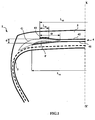
- the axial width L 41 of the first working layer 41 is equal to 234 mm.
- the axial width L 42 of the second working layer 42 is equal to 216 mm
- the layer 43 of circumferential reinforcing element has a width equal to 18 mm.
- the crown reinforcement is itself capped with a tread 5.
- a rubbery layer P is radially outwardly and in contact with the working crown ply 41.
- a layer G of rubbery mixture radially outside and in contact with the layer P of rubber mixtures comes into contact with the layer 42.
- the section G covers the end of said working layer 41 and extends beyond the axially outer end of said layer 41, while advantageously the axially outer end of the profile P does not go beyond the axially outer end of the layer 41.
- the set of profiles P and G forms a rubber layer called decoupling rubber.
- the combination of the layers of rubber mix P and G ensures in particular a decoupling between the working layer 41 and the end of the working layer 42 radially outer.
- the zone of engagement of the rubber mix profiles P and G between the two working plies 41 and 42 is defined by the thickness or more precisely the radial distance d between the end of the ply 42 and the ply 41 and by the axial width D of the rubber mix profile G between the axially inner end of said rubber mix profile G and the end of the axially narrow working crown ply 42.
- the radial distance d is equal to 3.5 mm.
- the axial distance D is equal to 20 mm, ie approximately 13.3 times the diameter ⁇ 2 of the reinforcement elements of the working ply 42, the diameter ⁇ 2 being equal to 1.5 mm.
- the two working plies 41 and 42 respectively have calenders, that is to say layers of rubbery mixture in contact with the reinforcing elements, consisting of the same rubber mix.
- the nature of the calendering may be the same for the different layers or different.
- the elastic moduli at 10% elongation of the layers of rubber mix P and G and of the "C" calendering layer of the working ply 42; respectively MP and MG and MC, are chosen such that they satisfy the following relation: MP ⁇ MG ⁇ MC.
- Such an embodiment of the tire 1 allows a reduction of the stresses of the calender layer of the working layer 42, through the layer of rubber mix G in contact with the working ply 42 to the layer of rubber mix P at contact of the working ply 41, which improves the resistance of the top architecture to the separation between the ends of the working plies 41 and 42.
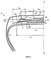
- the tire 21 still differs from that represented on the figure 1 in that it has an additional layer 243 which extends beyond the axially outer end of the layer 242 and which contacts the layer 241 to extend to the axially outer end of said layer 241.
- the axially outer end of the profile G is defined as being limited axially by the end of the layer 241.
- the layer 243 of circumferential reinforcement element has a width equal to 36 mm.
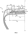
- the tire 31 differs from that shown on the figure 2 in that the additional layer 343 extends axially beyond the end of the working layer 341.
- the circumferential reinforcement element layer 343 has a width equal to 42 mm.
- Another variant embodiment of the invention relates to the case of an additional layer which extends axially beyond the end axially outside of the radially outer working layer and which remains at a distance greater than 1.5 mm from the end of the radially inner working layer.
- the end of the additional layer may be located axially between the ends of the two working layers or be located beyond the end of the axially widest working layer.
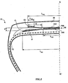
- the tire 41 differs from that shown on the figure 3 in that it comprises an additional layer 443 which is inserted between the two working layers 441 and 442.
- the layer 443 is indeed radially adjacent and internal to the layer 442; according to this embodiment of the invention, the additional layer 443 is also radially adjacent to the layer 441.
- the additional layer 443 may be at the sole contact of the working crown layer 442 or may be further is in contact only with the working crown layer 441 either radially adjacent and external to it being radially adjacent and interior thereto.
- the figure 5 illustrates an alternative embodiment of a tire 51 according to the invention which compared to the realization of the figure 1 further comprises a continuous layer 546 of circumferential reinforcing elements interposed between the working layers 541 and 542.
- This continuous layer 546 has a width L 546 equal to 196 mm, smaller than the widths of the working layers 541 and 542.
- the figure 6 illustrates yet another alternative embodiment of a tire 61 according to the invention which compared to the realization of the figure 2 has a protective layer 644 radially adjacent and external to the additional layer 643. According to this embodiment the axially inner end of the additional layer 643 is thus radially between the working layer 642 and the protective layer 644.
- This conventional tire does not have the additional layers and has a simple decoupling layer between the working layers. However, they include layers of protection and triangulation.
- the first endurance tests were carried out by equipping identical vehicles with each of the tires and by making straight-course journeys to each of the vehicles, the tires being subjected to loads greater than the nominal load to accelerate this type of test. .
- the reference vehicle comprising the usual tires is associated with a load per tire of 3600 kg at the beginning of rolling and evolves to reach a load of 4350 kg at the end of rolling.
- the vehicle comprising the tires according to the invention is associated with a load per tire of 3800 kg at the beginning of rolling and evolves to reach a load of 4800 kg at the end of rolling.
- the tests are stopped when the tire is damaged and / or no longer functions normally.
Abstract
Description
La présente invention concerne un pneumatique à armature de carcasse radiale et plus particulièrement un pneumatique destiné à équiper des véhicules portant de lourdes charges et roulant à vitesse soutenue, tels que, par exemple les camions, tracteurs, remorques ou bus routiers.The present invention relates to a tire with a radial carcass reinforcement and more particularly to a tire intended to equip vehicles carrying heavy loads and traveling at a high speed, such as, for example, trucks, tractors, trailers or road buses.
L'armature de renforcement ou renforcement des pneumatiques et notamment des pneumatiques de véhicules de type poids-lourds est à l'heure actuelle - et le plus souvent - constituée par empilage d'une ou plusieurs nappes désignées classiquement « nappes de carcasse », «nappes sommet », etc. Cette façon de désigner les armatures de renforcement provient du procédé de fabrication, consistant à réaliser une série de produits semi-finis en forme de nappes, pourvues de renforts filaires souvent longitudinaux, qui sont par la suite assemblées ou empilées afin de confectionner une ébauche de pneumatique. Les nappes sont réalisées à plat, avec des dimensions importantes, et sont par la suite coupées en fonction des dimensions d'un produit donné. L'assemblage des nappes est également réalisé, dans un premier temps, sensiblement à plat. L'ébauche ainsi réalisée est ensuite mise en forme pour adopter le profil toroïdal typique des pneumatiques. Les produits semi-finis dits « de finition » sont ensuite appliqués sur l'ébauche, pour obtenir un produit prêt pour la vulcanisation.The reinforcing reinforcement or reinforcement of tires and in particular tires of vehicles of the truck-type is at present - and most often - constituted by stacking one or more plies conventionally referred to as "carcass plies", " tablecloths ", etc. This method of designating reinforcing reinforcements comes from the manufacturing process, consisting in producing a series of semi-finished products in the form of plies, provided with wire reinforcements, often longitudinal, which are subsequently assembled or stacked in order to make a rough draft. pneumatic. Tablecloths are made flat, with large dimensions, and are subsequently cut according to the dimensions of a given product. The assembly of the plies is also made, initially, substantially flat. The blank thus produced is then shaped to adopt the typical toroidal profile of the tires. The so-called "finished" semi-finished products are then applied to the blank to obtain a product ready for vulcanization.
Un tel type de procédé "classique" implique, en particulier pour la phase de fabrication de l'ébauche du pneumatique, l'utilisation d'un élément d'ancrage (généralement une tringle), utilisé pour réaliser l'ancrage ou le maintien de l'armature de carcasse dans la zone des bourrelets du pneumatique. Ainsi, pour ce type de procédé, on effectue un retournement d'une portion de toutes les nappes composant l'armature de carcasse (ou d'une partie seulement) autour d'une tringle disposée dans le bourrelet du pneumatique. On crée de la sorte un ancrage de l'armature de carcasse dans le bourrelet.Such a type of "conventional" process involves, in particular for the manufacturing phase of the blank of the tire, the use of an anchoring element (generally a bead wire), used to carry out the anchoring or the maintenance of the carcass reinforcement in the area of the beads of the tire. Thus, for this type of process, a portion of all the plies constituting the carcass reinforcement (or of a part only) is turned around around a bead wire disposed in the bead of the tire. In this way, an anchoring of the carcass reinforcement in the bead is created.
La généralisation dans l'industrie de ce type de procédé classique, malgré de nombreuses variantes dans la façon de réaliser les nappes et les assemblages, a conduit l'homme du métier à utiliser un vocabulaire calqué sur le procédé ; d'où la terminologie généralement admise, comportant notamment les termes «nappes», «carcasse», «tringle», «conformation» pour désigner le passage d'un profil plat à un profil toroïdal, etc.The generalization in industry of this type of conventional method, despite many variations in the manner of making the plies and assemblies, led the skilled person to use a vocabulary modeled on the process; hence the generally accepted terminology, including in particular the terms "plies", "carcass", "rod", "conformation" to designate the passage from a flat profile to a toroidal profile, etc.
Il existe aujourd'hui des pneumatiques qui ne comportent à proprement parler pas de «nappes» ou de «tringles» d'après les définitions précédentes. Par exemple, le document
Par ailleurs, les pneumatiques décrits dans ce document ne disposent pas du "traditionnel" retournement de nappe carcasse autour d'une tringle. Ce type d'ancrage est remplacé par un agencement dans lequel on dispose de façon adjacente à ladite structure de renfort de flanc des fils circonférentiels, le tout étant noyé dans un mélange caoutchouteux d'ancrage ou de liaison.Moreover, the tires described in this document do not have the "traditional" reversal of carcass ply around a rod. This type of anchorage is replaced by an arrangement in which is disposed adjacent to said sidewall reinforcing structure circumferential son, all being embedded in a rubber mix anchoring or bonding.
Il existe également des procédés d'assemblage sur noyau toroïdal utilisant des produits semi-finis spécialement adaptés pour une pose rapide, efficace et simple sur un noyau central. Enfin, il est également possible d'utiliser un mixte comportant à la fois certains produits semi-finis pour réaliser certains aspects architecturaux (tels que des nappes, tringles, etc.), tandis que d'autres sont réalisés à partir de l'application directe de mélanges et/ou d'élément de renforcement.There are also toroidal core assembly methods using semi-finished products specially adapted for fast, efficient and simple laying on a central core. Finally, it is also possible to use a combination of both semi-finished products to achieve certain architectural aspects (such as tablecloths, rods, etc.), while others are made from the application direct blending and / or reinforcing element.
Dans le présent document, afin de tenir compte des évolutions technologiques récentes tant dans le domaine de la fabrication que pour la conception de produits, les termes classiques tels que «nappes», «tringles», etc., sont avantageusement remplacés par des termes neutres ou indépendants du type de procédé utilisé. Ainsi, le terme «renfort de type carcasse» ou «renfort de flanc» est valable pour désigner les éléments de renforcement d'une nappe carcasse dans le procédé classique, et les éléments de renforcement correspondants, en général appliqués au niveau des flancs, d'un pneumatique produit selon un procédé sans semi-finis. Le terme «zone d'ancrage» pour sa part, peut désigner tout autant le "traditionnel" retournement de nappe carcasse autour d'une tringle d'un procédé classique, que l'ensemble formé par les éléments de renforcement circonférentiels, le mélange caoutchouteux et les portions adjacentes de renfort de flanc d'une zone basse réalisée avec un procédé avec application sur un noyau toroïdal.In this document, in order to take account of recent technological developments in both manufacturing and product design, conventional terms such as "tablecloths", "rods", etc., are advantageously replaced by neutral terms. or independent of the type of process used. Thus, the term "carcass-type reinforcement" or "sidewall reinforcement" is used to designate the reinforcement elements of a carcass ply in the conventional method, and the corresponding reinforcing elements, generally applied at the flanks, to the carcass ply. a tire produced according to a process without semi-finished. The term "anchoring zone", for its part, can mean as much the "traditional" reversal of carcass ply around a rod of a conventional method, that the assembly formed by the circumferential reinforcing elements, the rubber mix and adjacent flank reinforcement portions of a low zone made with a method with application to a toroidal core.
D'une manière générale dans les pneumatiques de type poids-lourds, l'armature de carcasse est ancrée de part et d'autre dans la zone du bourrelet et est surmontée radialement par une armature de sommet constituée d'au moins deux couches, superposées et formées de fils ou câbles parallèles dans chaque couche. Elle peut également comprendre une couche de fils ou câbles métalliques à faible extensibilité faisant avec la direction circonférentielle un angle compris entre 45° et 90°, cette nappe, dite de triangulation, étant radialement située entre l'armature de carcasse et la première nappe de sommet dite de travail, formées de fils ou câbles parallèles présentant des angles au plus égaux à 45° en valeur absolue. La nappe de triangulation forme avec au moins ladite nappe de travail une armature triangulée, qui présente, sous les différentes contraintes qu'elle subit, peu de déformations, la nappe de triangulation ayant pour rôle essentiel de reprendre les efforts de compression transversale dont est l'objet l'ensemble des éléments de renforcement dans la zone du sommet du pneumatique.In general, in heavy-vehicle tires, the carcass reinforcement is anchored on both sides in the bead zone and is radially surmounted by a crown reinforcement consisting of at least two superposed layers. and formed of parallel wires or cables in each layer. It may also comprise a layer of low extensibility wires or metal cables forming with the circumferential direction an angle of between 45 ° and 90 °, this so-called triangulation ply being radially located between the carcass reinforcement and the first ply of plywood. so-called working top, formed of parallel wires or cables having angles at most equal to 45 ° in absolute value. The triangulation ply forms with at least said working ply a triangulated reinforcement, which presents, under the different stresses it undergoes, few deformations, the triangulation ply having the essential role of taking up the transverse compression forces of which the object all the reinforcing elements in the area of the crown of the tire.
L'armature de sommet comprend au moins une couche de travail ; lorsque ladite armature de sommet comporte au moins deux couches de travail, celles-ci sont formées d'éléments de renforcement métalliques inextensibles, parallèles entre eux dans chaque couche et croisés d'une couche à la suivante en faisant avec la direction circonférentielle des angles compris entre 10° et 45°. Lesdites couches de travail, formant l'armature de travail, peuvent encore être recouvertes d'au moins une couche dite de protection et formée d'éléments de renforcement avantageusement métalliques et extensibles, dits élastiques.The crown reinforcement comprises at least one working layer; when said crown reinforcement comprises at least two working layers, these are formed of inextensible metallic reinforcement elements parallel to each other in each layer and crossed from one layer to the next, making angles with the circumferential direction between 10 ° and 45 °. Said working layers, forming the working armature, can still be covered with at least one so-called protective layer and formed of advantageously metallic and extensible reinforcing elements, called elastic elements.
Dans le cas des pneumatiques pour véhicules "Poids-Lourds", une seule couche de protection est habituellement présente et ses éléments de protection sont, dans la plupart des cas, orientés dans la même direction et avec le même angle en valeur absolue que ceux des éléments de renforcement de la couche de travail radialement la plus à l'extérieur et donc radialement adjacente. Dans le cas de pneumatiques de Génie Civil destinés aux roulages sur sols plus ou moins accidentés, la présence de deux couches de protection est avantageuse, les éléments de renforcement étant croisés d'une couche à la suivante et les éléments de renforcement de la couche de protection radialement intérieure étant croisés avec les éléments de renforcement inextensibles de la couche de travail radialement extérieure et adjacente à ladite couche de protection radialement intérieure.In the case of tires for heavy goods vehicles, only one layer of protection is usually present and its protective elements are, in most cases, oriented in the same direction and with the same angle in absolute value as those of reinforcement elements of the radially outermost working layer and thus radially adjacent. In the case of civil engineering tires intended for driving on more or less uneven ground, the presence of two layers of protection is advantageous, the reinforcing elements being crossed from one layer to the next and the reinforcement elements of the layer of radially inner protection being crossed with the inextensible reinforcing elements of the radially outer working layer and adjacent to said radially inner protective layer.
Des câbles sont dits inextensibles lorsque lesdits câbles présentent sous une force de traction égale à 10% de la force de rupture un allongement relatif au plus égal à 0,2%.Cables are said to be inextensible when said cables have under tensile force equal to 10% of the breaking force a relative elongation of at most 0.2%.
Des câbles sont dits élastiques lorsque lesdits câbles présentent sous une force de traction égale à la charge de rupture un allongement relatif au moins égal à 4%.Cables are said to be elastic when said cables have under a tensile force equal to the breaking load a relative elongation of at least 4%.
La direction circonférentielle du pneumatique, ou direction longitudinale, est la direction correspondant à la périphérie du pneumatique et définie par la direction de roulement du pneumatique.The circumferential direction of the tire, or longitudinal direction, is the direction corresponding to the periphery of the tire and defined by the rolling direction of the tire.
La direction transversale ou axiale du pneumatique est parallèle à l'axe de rotation du pneumatique.The transverse or axial direction of the tire is parallel to the axis of rotation of the tire.
La direction radiale est une direction coupant l'axe de rotation du pneumatique et perpendiculaire à celui-ci.The radial direction is a direction intersecting the axis of rotation of the tire and perpendicular to it.
L'axe de rotation du pneumatique est l'axe autour duquel il tourne en utilisation normale.The axis of rotation of the tire is the axis around which it rotates under normal use.
Un plan radial ou méridien est un plan qui contient l'axe de rotation du pneumatique.A radial or meridian plane is a plane which contains the axis of rotation of the tire.
Le plan médian circonférentiel, ou plan équatorial, est un plan perpendiculaire à l'axe de rotation du pneu et qui divise le pneumatique en deux moitiés.The circumferential median plane, or equatorial plane, is a plane perpendicular to the axis of rotation of the tire and which divides the tire into two halves.
Certains pneumatiques actuels, dits "routiers", sont destinés à rouler à grande vitesse et sur des trajets de plus en plus longs, du fait de l'amélioration du réseau routier et de la croissance du réseau autoroutier dans le monde. L'ensemble des conditions, sous lesquelles un tel pneumatique est appelé à rouler, permet sans aucun doute un accroissement du nombre de kilomètres parcourus, l'usure du pneumatique étant moindre ; par contre l'endurance de ce dernier et en particulier de l'armature de sommet s'en trouve pénalisée.Some current tires, called "road", are intended to run at high speed and on longer and longer journeys, because of the improvement of the road network and the growth of the motorway network in the world. The set of conditions under which such a tire is called to roll, undoubtedly allows an increase in the number of kilometers traveled, the wear of the tire being less; on the other hand, the endurance of the latter and in particular of the crown reinforcement is penalized.
Il existe en effet des contraintes au niveau de l'armature de sommet et plus particulièrement des contraintes de cisaillement entre les couches de sommet, alliées à une élévation non négligeable de la température de fonctionnement au niveau des extrémités de la couche de sommet axialement la plus courte, qui ont pour conséquence l'apparition et la propagation de fissures de la gomme au niveau desdites extrémités.There are indeed constraints at the level of the crown reinforcement and more particularly shear stresses between the crown layers, combined with a not insignificant increase in the operating temperature at the ends of the axially most vertically facing crown layer. short, which result in the appearance and propagation of cracks of the rubber at said ends.
Afin d'améliorer l'endurance de l'armature de sommet du type de pneumatique étudié, des solutions relatives à la structure et qualité des couches et/ou profilés de mélanges caoutchouteux qui sont disposés entre et/ou autour dés extrémités de nappes et plus particulièrement des extrémités de la nappe axialement la plus courte ont déjà été apportées.In order to improve the endurance of the crown reinforcement of the tire type studied, solutions relating to the structure and quality of the layers and / or profiles of rubber compounds which are arranged between and / or around the ends of the sheets and more particularly ends of the axially shorter web have already been made.
Le brevet
Le brevet
La demande
Les roulages prolongés des pneumatiques ainsi construits ont fait apparaître des ruptures de fatigue des câbles de la nappe additionnelle et plus particulièrement des bords de ladite nappe, que la nappe dite de triangulation soit présente ou non.The prolonged rolling of the tires thus constructed have revealed fatigue fractures of the cables of the additional ply and more particularly the edges of said ply, whether the so-called triangulation ply is present or not.
Pour remédier à de tels inconvénients et améliorer l'endurance de l'armature de sommet de ces pneumatiques, la demande française
La demande de brevet
Un but de l'invention est de fournir des pneumatiques pour véhicules « Poids-Lourds » dont les performances d'endurance sont encore améliorées par rapport aux pneumatiques usuels.An object of the invention is to provide tires for vehicles "heavy-weight" whose endurance performance is further improved over conventional tires.
Ce but est atteint selon l'invention par un pneumatique à armature de carcasse radiale comprenant une armature de sommet formée d'au moins deux couches de sommet de travail d'éléments de renforcement inextensibles, croisés d'une nappe à l'autre en faisant avec la direction circonférentielle des angles compris entre 10° et 45°, elle-même coiffée radialement d'une bande de roulement, ladite bande de roulement étant réunie à deux bourrelets par l'intermédiaire de deux flancs, lesdites deux nappes ayant des largeurs axiales inégales, au moins un premier profilé P de mélange caoutchouteux séparant la nappe d'éléments de renforcement axialement la plus large d'au moins une extrémité d'une deuxième nappe axialement plus étroite que la nappe axialement la plus large, ledit profilé P étant radialement séparé au moins en partie du calandrage C de ladite nappe d'éléments de renforcement axialement plus étroite par un second profilé de mélange caoutchouteux G, et lesdits premier et second profilés de mélange caoutchouteux P et G et ledit calandrage C ayant respectivement des modules sécants d'élasticité sous tension à 10 % d'allongement MP, MG, MC de sorte que MC ≥ MG > MP, ledit pneumatique comprenant additionnellement dans chaque épaule au moins une couche d'éléments de renforcement, parallèles entre eux dans la couche et orientés circonférentiellement, l'extrémité axialement intérieure de ladite couche étant radialement adjacente au bord d'une couche de sommet de travail et au moins une partie de la couche additionnelle étant radialement et/ou axialement adjacente au bord de la couche de travail axialement la plus large.This object is achieved according to the invention by a radial carcass reinforcement tire comprising a crown reinforcement formed of at least two working crown layers of inextensible reinforcing elements, crossed from one sheet to the other by making with the circumferential direction of the angles between 10 ° and 45 °, itself capped radially with a tread, said tread being joined to two beads by means of two sidewalls, said two plies having axial widths at least one first P-profile of rubber mixture separating the ply of axially widest reinforcing elements from at least one end of a second ply axially narrower than the axially widest ply, said P-section being radially at least partly separated from the calendering C of said sheet of axially narrower reinforcing elements by a second section of rubber mix G, and said first and second rubbery profile P and G and said calender C having tensile modulus tensile elastic moduli at 10% elongation MP, MG, MC such that MC ≥ MG> MP, said tire comprising additionally in each shoulder at least one layer of reinforcing elements, parallel to each other in the layer and oriented circumferentially, the axially inner end of said layer being radially adjacent to the edge of a working crown layer and at least a part of the additional layer being radially and / or axially adjacent to the edge of the axially widest working layer.
Conformément à l'invention, l'invention, soit la couche additionnelle est uniquement adjacente à la couche de travail axialement la plus large, soit la couche additionnelle est adjacente à deux couches de travail et l'extrémité axialement extérieure du profilé caoutchouteux G et/ou P est située à une distance du plan équatorial du pneumatique inférieure à la distance séparant dudit plan l'extrémité de la nappe d'éléments de renforcement axialement la plus large.According to the invention, the invention, ie the additional layer is only adjacent to the axially widest working layer, or the additional layer is adjacent to two working layers and the axially outer end of the rubber profile G and / or P is located at a distance from the equatorial plane of the tire less than the distance separating from said plane the end of the ply of axially widest reinforcing elements.
Selon un mode préféré de réalisation de l'invention, l'extrémité axialement intérieure de ladite couche additionnelle est radialement adjacente au bord de la couche de sommet de travail axialement la moins large et de préférence radialement extérieure à ladite couche de travail axialement la moins large.According to a preferred embodiment of the invention, the axially inner end of said additional layer is radially adjacent to the edge of the axially least wide working crown layer and preferably radially outer to said axially narrow working layer. .
Des éléments de renforcement circonférentiels sont des éléments de renforcement qui font avec la direction circonférentielle des angles compris dans l'intervalle + 2,5°, - 2,5° autour de 0°.Circumferential reinforcing elements are reinforcing elements which make angles with the circumferential direction in the range + 2.5 °, - 2.5 ° around 0 °.
Les mesures de module sont effectuées en traction selon la norme AFNOR-NFT-46002 de septembre 1988 : on mesure en seconde élongation (i.e., après un cycle d'accommodation) le module sécant nominal (ou contrainte apparente, en MPa) à 10% d'allongement (conditions normales de température et d'hygrométrie selon la norme AFNOR-NFT-40101 de décembre 1979).The modulus measurements are carried out in tension according to the AFNOR-NFT-46002 standard of September 1988: the secant modulus (or apparent stress, in MPa) at 10% is measured in second elongation (ie, after an accommodation cycle). of elongation (normal temperature and hygrometry conditions according to the AFNOR-NFT-40101 standard of December 1979).
Les largeurs axiales des couches d'éléments de renforcement ou positions axiales des extrémités desdites couches sont mesurées sur une coupe transversale d'un pneumatique, le pneumatique étant donc dans un état non gonflé.The axial widths of the layers of reinforcing elements or axial positions of the ends of said layers are measured on a cross section of a tire, the tire therefore being in an uninflated state.
Les essais réalisés avec des pneumatiques ainsi définis selon l'invention ont mis en évidence que les performances en terme d'endurance du pneumatique sont améliorées par rapport à des pneumatiques de conception plus traditionnelles ne comportant pas une combinaison conforme à l'invention de profilés de mélange caoutchouteux et de couches additionnelles.The tests carried out with tires thus defined according to the invention have demonstrated that the performance in terms of endurance of the tire is improved compared to more traditional design tires not comprising a combination according to the invention of rubbery mixture and additional layers.
La combinaison des couches de mélanges caoutchouteux P et G, de par le choix de leurs modules d'élasticité respectifs MP et MG autorise tout d'abord une amélioration de la résistance de l'architecture sommet à la séparation entre les extrémités des nappes de travail. La présence de ces couches de mélange caoutchouteux semble en effet permettre, du fait du découplage des nappes ainsi obtenu, de protéger notamment l'extrémité de la nappe la plus étroite et ainsi prévenir ou tout au moins retarder l'apparition d'une délamination de la dite extrémité de la nappe la plus étroite axialement. Ensuite, il semble que cet effet soit accentué par la combinaison avec la couche additionnelle.The combination of the layers of rubber mixes P and G, by the choice of their respective elastic moduli MP and MG, firstly allows an improvement of the resistance of the top architecture to the separation between the ends of the working plies. . The presence of these layers of rubber mix seems to allow, because of the decoupling of the sheets thus obtained, in particular to protect the end of the narrowest layer and thus prevent or at least delay the appearance of a delamination of said end of the narrower ribbon axially. Then, it seems that this effect is accentuated by the combination with the additional layer.
Il faut entendre par nappes couplées des nappes dont les éléments de renforcement respectifs sont séparés radialement d'au plus 1.5 mm, ladite épaisseur de caoutchouc étant mesurée radialement entre les génératrices respectivement supérieure et inférieure desdits éléments de renforcement.Coupled plies are understood to mean plies whose respective reinforcing elements are separated radially by at most 1.5 mm, said thickness of rubber being measured radially between the respectively upper and lower generatrices of said reinforcing elements.
De préférence, la somme des épaisseurs respectives des profilés de mélange caoutchouteux P et G, mesurée à l'extrémité de la nappe la moins large des deux nappes considérées, sera préférentiellement comprise entre 30 % et 80 % de l'épaisseur globale de mélange caoutchouteux entre génératrices de câbles respectivement des deux nappes : une épaisseur inférieure à 30 % ne permettant pas d'obtenir des résultats probants, et une épaisseur supérieure à 80 % étant inutile vis à vis de l'amélioration à la résistance à la séparation entre nappes et désavantageux du point de vue coût.Preferably, the sum of the respective thicknesses of the rubber mix profiles P and G, measured at the end of the thinnest layer of the two sheets considered, will preferably be between 30% and 80% of the overall thickness of the rubbery mixture. between cable generators respectively of the two layers: a thickness of less than 30% does not make it possible to obtain convincing results, and a thickness greater than 80% is useless with regard to the improvement in the resistance to separation between layers and disadvantageous from the cost point of view.
Une première variante de réalisation de l'invention prévoit que l'extrémité axialement extérieure de ladite couche additionnelle est située à une distance du plan équatorial du pneumatique inférieure ou égale à la distance séparant dudit plan l'extrémité de la couche de travail à laquelle elle est adjacente. Selon cette variante de réalisation de l'invention, l'extrémité axialement extérieure de la couche additionnelle est donc axialement intérieure à l'extrémité d'au moins la couche de travail adjacente à ladite couche additionnelle.A first embodiment of the invention provides that the axially outer end of said additional layer is located at a distance from the equatorial plane of the tire less than or equal to the distance separating said plane from the end of the working layer to which it is adjacent. According to this embodiment of the invention, the axially outer end of the additional layer is therefore axially inner to the end of at least the working layer adjacent to said additional layer.
Une seconde variante de réalisation de l'invention prévoit que l'extrémité axialement extérieure de ladite couche additionnelle est axialement extérieure à l'extrémité de la couche de sommet de travail à laquelle elle est adjacente.A second embodiment of the invention provides that the axially outer end of said additional layer is axially external to the end of the working crown layer to which it is adjacent.
Une réalisation préférée de l'invention prévoit que l'extrémité axialement extérieure dudit premier profilé P est située à une distance du plan équatorial du pneumatique inférieure à la distance séparant dudit plan l'extrémité de la nappe d'éléments de renforcement axialement la plus large.A preferred embodiment of the invention provides that the axially outer end of said first profile P is situated at a distance from the equatorial plane of the tire less than the distance separating said plane from the end of the ply of axially widest reinforcing elements. .
Une réalisation avantageuse de l'invention prévoit que l'extrémité axialement extérieure du second profilé de mélange caoutchouteux G est située à une distance dudit plan au moins égale à la demi-largeur de ladite nappe d'éléments de renforcement axialement plus étroite. Selon cette réalisation de l'invention, l'extrémité de ladite nappe axialement la plus étroite est radialement séparée de la nappe la plus large par la superposition radiale des deux profilés de mélange caoutchouteux P et G.An advantageous embodiment of the invention provides that the axially outer end of the second rubber mix profile G is located at a distance from said plane at least equal to half the width of said ply of axially narrower reinforcement elements. According to this embodiment of the invention, the end of said axially narrow ply is radially separated from the widest ply by the radial superposition of the two rubber mix profiles P and G.
Selon une réalisation préférée de l'invention, le second profilé de mélange caoutchouteux G a son extrémité axialement intérieure située à une distance du plan équatorial au plus égale à la distance séparant dudit plan l'extrémité axialement intérieure dudit premier profilé de mélange caoutchouteux P. Selon cette réalisation et notamment lorsque l'extrémité axialement extérieure du second profilé de mélange caoutchouteux G est située à une distance dudit plan au moins égale à la demi-largeur de ladite nappe d'éléments de renforcement axialement plus étroite, le premier profilé de mélange caoutchouteux P n'est pas au contact de ladite nappe axialement la plus étroite.According to a preferred embodiment of the invention, the second rubber compound profile G has its axially inner end located at a distance from the equatorial plane at most equal to the distance separating from said plane the axially inner end. of said first rubber compound profile P. According to this embodiment and in particular when the axially outer end of the second rubber compound profile G is located at a distance from said plane at least equal to half the width of said sheet of reinforcement elements axially. narrower, the first rubbery mix profile P is not in contact with said axially narrow ply.
Selon un mode de réalisation avantageux de l'invention, la couche de sommet de travail axialement la plus large est radialement à l'intérieur des autres couches de sommet de travail.According to an advantageous embodiment of the invention, the axially widest working crown layer is radially inside the other working crown layers.
Selon ce mode de réalisation le premier profilé de mélange caoutchouteux G est alors au moins en partie radialement extérieur au second profilé de mélange caoutchouteux P.According to this embodiment, the first rubber compound profile G is then at least partially radially external to the second rubber compound profile P.
De préférence encore, la largeur axiale D du profilé P et/ou G comprise entre l'extrémité axialement la plus à l'intérieure du profilé P et/ou G et l'extrémité de la nappe de sommet de travail axialement la moins large est telle que : ![]()
avec φ2, diamètre des éléments de renforcement de la nappe de sommet de travail axialement la moins large. Une telle relation définit une zone d'engagement entre le profilé P et/ou G de mélanges caoutchouteux et la nappe de travail axialement la moins large. Un tel engagement en dessous d'une valeur égale à trois fois le diamètre des éléments de renforcement de la nappe de travail radialement extérieure peut ne pas être suffisant pour obtenir un découplage des nappes de travail pour notamment obtenir une atténuation des sollicitations en extrémité de la nappe de travail axialement la moins large. Une valeur de cet engagement supérieure à vingt fois le diamètre des éléments de renforcement de la nappe de travail axialement la moins large peut conduire à une diminution trop importante de la rigidité de dérive de l'armature de sommet du pneumatique.More preferably, the axial width D of the profile P and / or G between the axially innermost end of the profile P and / or G and the end of the axially shallower working crown ply is such as: ![]()
with φ2, the diameter of the reinforcing elements of the axially the least wide working crown ply. Such a relationship defines a zone of engagement between the profile P and / or G of rubber mixes and the working ply axially the smallest. Such an engagement below a value equal to three times the diameter of the reinforcing elements of the radially outer working ply may not be sufficient to obtain a decoupling of the working plies in particular to obtain an attenuation of the stresses at the end of the ply. working ply axially the least wide. A value of this engagement greater than twenty times the diameter of the reinforcing elements of the axially narrower working ply can lead to an excessive reduction in the rigidity of the crown reinforcement of the tire.
De préférence, la largeur axiale D du profilé P et/ou G comprise entre l'extrémité axialement la plus à l'intérieure du profilé P et/ou G et l'extrémité axialement extérieure de la couche de sommet de travail axialement la moins large est supérieure à 5 mm.Preferably, the axial width D of the profile P and / or G between the axially innermost end of the profile P and / or G and the axially outer end of the axially smaller working crown layer. is greater than 5 mm.
L'invention prévoit encore de préférence que l'épaisseur cumulée des profilés P et G, à l'extrémité axialement extérieure de la nappe de sommet de travail axialement la moins large, présente une épaisseur telle que la distance radiale d entre les deux nappes de sommet de travail, séparées par le profilé P et/ou G, vérifie la relation : ![]()
avec φ2, diamètre des éléments de renforcement de la nappe de sommet de travail axialement la moins large.The invention further preferably provides that the cumulative thickness of the profiles P and G, at the axially outer end of the axially shallower working crown ply, has a thickness such that the radial distance d between the two plies of top, separated by the profile P and / or G, verifies the relation: ![]()
with φ2, the diameter of the reinforcing elements of the axially the least wide working crown ply.
La distance d est mesurée de câble à câble, c'est-à-dire entre le câble d'une première nappe de travail et le câble d'une seconde nappe de travail. En d'autres termes, cette distance d englobe l'épaisseur du profilé P et/ou G et les épaisseurs respectives des mélanges caoutchouteux de calandrage, radialement extérieure aux câbles de la nappe de travail radialement intérieure et radialement intérieure aux câbles de la nappe de travail radialement extérieure.The distance d is measured from cable to cable, that is to say between the cable of a first working ply and the cable of a second ply of work. In other words, this distance d includes the thickness of the profile P and / or G and the respective thicknesses of the calendering rubber mixes radially external to the cables of the radially inner and radially inner working ply of the ribbon cables. radially external work.
Les différentes mesures d'épaisseur sont effectuées sur une coupe transversale d'un pneumatique, le pneumatique étant donc dans un état non gonflé.The various thickness measurements are made on a cross section of a tire, the tire therefore being in a non-inflated state.
De préférence encore, la différence entre la largeur axiale de la couche de sommet de travail axialement la plus large et la largeur axiale de la couche de sommet de travail axialement la moins large est comprise entre 5 et 30 mm.More preferably, the difference between the axial width of the axially widest working crown layer and the axial width of the axially least wide working crown layer is between 5 and 30 mm.
Selon une variante de réalisation avantageuse de l'invention, l'angle formé avec la direction circonférentielle par les éléments de renforcement des couches de sommet de travail est inférieur à 30° et de préférence inférieur à 25°.According to an advantageous embodiment of the invention, the angle formed with the circumferential direction by the reinforcement elements of the working crown layers is less than 30 ° and preferably less than 25 °.
Selon une variante de réalisation de l'invention, les couches de sommet de travail comportent des éléments de renforcement, croisés d'une nappe à l'autre, faisant avec la direction circonférentielle des angles variables selon la direction axiale, lesdits angles étant supérieurs sur les bords axialement extérieurs des couches d'éléments de renforcement par rapport aux angles desdits éléments mesurés au niveau du plan médian circonférentiel. Une telle réalisation de l'invention permet d'augmenter la rigidité circonférentielle dans certaines zones et au contraire de la diminuer dans d'autres, notamment pour diminuer les mises en compression de l'armature de carcasse.According to an alternative embodiment of the invention, the working crown layers comprise reinforcing elements, crossed from one ply to the other, making with the circumferential direction variable angles in the axial direction, said angles being greater on the axially outer edges of the reinforcing element layers with respect to the angles of said elements measured at the circumferential mid-plane. Such an embodiment of the invention makes it possible to increase the circumferential rigidity in certain zones and, conversely, to reduce it in others, in particular to reduce the compression of the carcass reinforcement.
Une réalisation préférée de l'invention prévoit encore que l'armature de sommet est complétée radialement à l'extérieur par au moins une couche supplémentaire, dite de protection, d'éléments de renforcement dits élastiques, orientés par rapport à la direction circonférentielle avec un angle compris entre 10° et 45° et de même sens que l'angle formé par les éléments inextensibles de la couche de travail qui lui est radialement adjacente.A preferred embodiment of the invention further provides that the crown reinforcement is completed radially on the outside by at least one additional protective layer of so-called elastic reinforcing elements oriented with respect to the circumferential direction with a angle between 10 ° and 45 ° and in the same direction as the angle formed by the inextensible elements of the working layer which is radially adjacent thereto.
La couche de protection peut avoir une largeur axiale inférieure à la largeur axiale de la couche de travail la moins large. Ladite couche de protection peut aussi avoir une largeur axiale supérieure à la largeur axiale de la couche de travail la moins large, telle qu'elle recouvre les bords de la couche de travail la moins large. La couche de protection formée d'éléments de renforcement élastiques peut, dans le dernier cas cité ci-dessus, être d'une part éventuellement découplée des bords de ladite couche de travail la moins large par des profilés, et avoir d'autre part une largeur axiale inférieure ou supérieure à la largeur axiale de la couche de sommet la plus large.The protective layer may have an axial width smaller than the axial width of the narrower working layer. Said protective layer may also have an axial width greater than the axial width of the narrower working layer, such that it covers the edges of the narrower working layer. The protective layer formed of elastic reinforcing elements may, in the last case mentioned above, be on the one hand possibly decoupled from the edges of said least-extensive working layer by profiles, and on the other hand have a axial width less than or greater than the axial width of the widest vertex layer.
Lorsque la couche de protection est axialement plus étroite que la couche de sommet de travail axialement la moins large, que ladite couche de sommet de travail est radialement la couche de travail la plus à l'extérieur, l'invention prévoit avantageusement que le bord de la couche de protection est radialement adjacent et de préférence radialement extérieur à au moins le bord axialement intérieur de la couche additionnelle.When the protective layer is axially narrower than the axially narrower working crown layer, that said working crown layer is radially the outermost working layer, the invention advantageously provides that the the protective layer is radially adjacent and preferably radially external to at least the axially inner edge of the additional layer.
En comparaison des variantes précédentes de l'invention, pour obtenir une telle réalisation de l'invention, selon laquelle le bord de la couche de protection est radialement adjacente et extérieure à la couche additionnelle, soit l'extrémité de la couche de protection est axialement plus à l'extérieur, soit l'extrémité axialement intérieure de la couche additionnelle est axialement plus à l'intérieur. En d'autres termes, soit la couche de protection est axialement plus large, soit la couche additionnelle est axialement plus large en étant allongée axialement vers l'intérieur.In comparison with the preceding variants of the invention, to obtain such an embodiment of the invention, according to which the edge of the protective layer is radially adjacent and external to the additional layer, or the end of the protective layer is axially further outside, the axially inner end of the additional layer is axially further inland. In other words, either the protective layer is axially wider or the additional layer is axially wider by being axially elongated inwards.
Selon l'un quelconque des modes de réalisation de l'invention évoqué précédemment, l'armature de sommet peut encore être complétée, par exemple radialement entre l'armature de carcasse et la couche de travail radialement la plus à l'intérieur, par une couche de triangulation constituée d'éléments de renforcement inextensibles faisant, avec la direction circonférentielle, un angle supérieur à 40° et de préférence de même sens que celui de l'angle formé par les éléments de renforcement de la couche radialement la plus proche de l'armature de carcasse.According to any of the embodiments of the invention mentioned above, the crown reinforcement can be further completed, for example radially between the carcass reinforcement and the radially innermost working layer, by a triangulation layer consisting of inextensible reinforcing elements making, with the circumferential direction, an angle greater than 40 ° and preferably in the same direction as that of the angle formed by the reinforcing elements of the layer radially closest to the carcass reinforcement.
Selon une première variante de réalisation de l'invention, les éléments de renforcement de la couche additionnelle d'éléments de renforcement circonférentiels sont des éléments de renforcement métalliques.According to a first variant embodiment of the invention, the reinforcing elements of the additional layer of circumferential reinforcing elements are metal reinforcing elements.
Selon une autre variante de réalisation de l'invention, les éléments de renforcement de la couche additionnelle d'éléments de renforcement circonférentiels sont des éléments de renforcement textiles.According to another embodiment of the invention, the reinforcing elements of the additional layer of circumferential reinforcing elements are textile reinforcement elements.
Un mode de réalisation avantageux de l'invention prévoit que l'armature de sommet du pneumatique comporte en outre au moins une couche continue d'éléments de renforcement circonférentiels dont la largeur axiale est de préférence inférieure à la largeur axiale de la couche de sommet de travail axialement la plus large.An advantageous embodiment of the invention provides that the crown reinforcement of the tire further comprises at least one continuous layer of circumferential reinforcement elements whose axial width is preferably less than the axial width of the crown layer of the tire. axially the widest work.
Les largeurs axiales des couches continues d'éléments de renforcement sont mesurées sur une coupe transversale d'un pneumatique, le pneumatique étant dans un état non gonflé.The axial widths of the continuous layers of reinforcing elements are measured on a cross section of a tire, the tire being in an uninflated state.
La présence dans le pneumatique selon l'invention d'au moins une couche continue d'éléments de renforcement circonférentiels peut permettre de contribuer à l'obtention de rayons de courbures axiales quasi-infinis des différentes couches de renforcement dans une zone centrée sur le plan médian circonférentiel, ce qui contribue aux performances d'endurance du pneumatique.The presence in the tire according to the invention of at least one continuous layer of circumferential reinforcing elements can make it possible to contribute to obtaining quasi-infinite axial curvature radii of the various reinforcement layers in a zone centered on the plane circumferential median, which contributes to the endurance performance of the tire.
Selon un mode de réalisation avantageux de l'invention, les éléments de renforcement d'au moins une couche continue d'éléments de renforcement circonférentiels sont des éléments de renforcement métalliques présentant un module sécant à 0,7 % d'allongement compris entre 10 et 120 GPa et un module tangent maximum inférieur à 150 GPa.According to an advantageous embodiment of the invention, the reinforcing elements of at least one continuous layer of circumferential reinforcing elements are metal reinforcing elements having a secant modulus at 0.7% elongation between 10 and 120 GPa and a maximum tangent modulus less than 150 GPa.
Selon une réalisation préférée, le module sécant des éléments de renforcement à 0,7 % d'allongement est inférieur à 100 GPa et supérieur à 20 GPa, de préférence compris entre 30 et 90 GPa et de préférence encore inférieur à 80 GPa.According to a preferred embodiment, the secant modulus of the reinforcing elements at 0.7% elongation is less than 100 GPa and greater than 20 GPa, preferably between 30 and 90 GPa and more preferably less than 80 GPa.
De préférence également, le module tangent maximum des éléments de renforcement est inférieur à 130 GPa et de préférence encore inférieur à 120 GPa.Also preferably, the maximum tangent modulus of the reinforcing elements is less than 130 GPa and more preferably less than 120 GPa.
Les modules exprimés ci-dessus sont mesurés sur une courbe contrainte de traction en fonction de l'allongement déterminée avec une précontrainte de 20 MPa ramenée à la section de métal de l'élément de renforcement, la contrainte de traction correspondant à une tension mesurée ramenée à la section de métal de l'élément de renforcement.The modules expressed above are measured on a tensile stress curve as a function of the elongation determined with a preload of 20 MPa brought back to the metal section of the reinforcement element, the tensile stress corresponding to a measured tension brought back to the metal section of the reinforcing element.
Les modules des mêmes éléments de renforcement peuvent être mesurés sur une courbe contrainte de traction en fonction de l'allongement déterminée avec une précontrainte de 10 MPa ramenée à la section globale de l'élément de renforcement, la contrainte de traction correspondant à une tension mesurée ramenée à la section globale de l'élément de renforcement. La section globale de l'élément de renforcement est la section d'un élément composite constitué de métal et de caoutchouc, ce dernier ayant notamment pénétré l'élément de renforcement pendant la phase de cuisson du pneumatique.The modules of the same reinforcing elements can be measured on a tensile stress curve as a function of the elongation determined with a preload of 10 MPa reduced to the overall section of the reinforcing element, the tensile stress corresponding to a measured tension. brought back to the global section of the element of enhancement. The overall section of the reinforcing element is the section of a composite element made of metal and rubber, the latter having in particular penetrated the reinforcing element during the baking phase of the tire.
Selon cette formulation relative à la section globale de l'élément de renforcement, les éléments de renforcement d'au moins une couche d'éléments de renforcement circonférentiels sont des éléments de renforcement métalliques présentant un module sécant à 0,7 % d'allongement compris entre 5 et 60 GPa et un module tangent maximum inférieur à 75 GPa.According to this formulation relating to the overall section of the reinforcing element, the reinforcing elements of at least one layer of circumferential reinforcing elements are metal reinforcing elements having a secant modulus at 0.7% of elongation included between 5 and 60 GPa and a maximum tangent modulus less than 75 GPa.
Selon une réalisation préférée, le module sécant des éléments de renforcement à 0,7 % d'allongement est inférieur à 50 GPa et supérieur à 10 GPa, de préférence compris entre 15 et 45 GPa et de préférence encore inférieure à 40 GPa.According to a preferred embodiment, the secant modulus of the reinforcing elements at 0.7% elongation is less than 50 GPa and greater than 10 GPa, preferably between 15 and 45 GPa and more preferably less than 40 GPa.
De préférence également, le module tangent maximum des éléments de renforcement est inférieur à 65 GPa et de préférence encore inférieur à 60 GPa.Also preferably, the maximum tangent modulus of the reinforcing elements is less than 65 GPa and more preferably less than 60 GPa.
Selon un mode de réalisation préféré, les éléments de renforcements d'au moins une couche continue d'éléments de renforcement circonférentiels sont des éléments de renforcement métalliques présentant une courbe contrainte de traction en fonction de l'allongement relatif ayant des faibles pentes pour les faibles allongements et une pente sensiblement constante et forte pour les allongements supérieurs. De tels éléments de renforcement de la couche continue d'éléments de renforcement circonférentiels sont habituellement dénommés éléments "bi-module".According to a preferred embodiment, the reinforcing elements of at least one continuous layer of circumferential reinforcing elements are metal reinforcing elements having a stress-strain curve as a function of the relative elongation having small slopes for the weak ones. elongations and a substantially constant and strong slope for the higher elongations. Such reinforcing elements of the continuous layer of circumferential reinforcing elements are usually referred to as "bi-module" elements.
Selon une réalisation préférée de l'invention, la pente sensiblement constante et forte apparaît à partir d'un allongement relatif compris entre 0,1% et 0,5%.According to a preferred embodiment of the invention, the substantially constant and strong slope appears from a relative elongation of between 0.1% and 0.5%.
Les différentes caractéristiques des éléments de renforcement énoncées ci-dessus sont mesurées sur des éléments de renforcement prélevés sur des pneumatiques.The different characteristics of the reinforcing elements mentioned above are measured on reinforcing elements taken from tires.
Des éléments de renforcement plus particulièrement adaptés à la réalisation d'au moins une couche continue d'éléments de renforcement circonférentiels selon l'invention sont par exemple des assemblages de formule 21.23, dont la construction est 3x(0.26+6x0.23) 4.4/6.6 SS ; ce câble à torons est constitué de 21 fils élémentaires de formule 3 x (1+6), avec 3 torons tordus ensembles chacun constitué de 7 fils, un fil formant une âme centrale de diamètre égal à 26/100 mm et 6 fils enroulés de diamètre égal à 23/100 mm. Un tel câble présente un module sécant à 0,7% égal à 45 GPa et un module tangent maximum égal à 98 GPa, mesurés sur une courbe contrainte de traction en fonction de l'allongement déterminée avec une précontrainte de 20 MPa ramenée à la section de métal de l'élément de renforcement, la contrainte de traction correspondant à une tension mesurée ramenée à la section de métal de l'élément de renforcement. Sur une courbe contrainte de traction en fonction de l'allongement déterminée avec une précontrainte de 10 MPa ramenée à la section globale de l'élément de renforcement, la contrainte de traction correspondant à une tension mesurée ramenée à la section globale de l'élément de renforcement, ce câble de formule 21.23 présente un module sécant à 0,7% égal à 23 GPa et un module tangent maximum égal à 49 GPa.Reinforcing elements that are more particularly suitable for producing at least one continuous layer of circumferential reinforcing elements according to the invention are, for example, assemblies of formula 21.23, the construction of which is 3x (0.26 + 6x0.23). 4.4 / 6.6 SS; this strand cable consists of 21 elementary wires of formula 3 x (1 + 6), with 3 twisted strands each consisting of 7 wires, a wire forming a central core of diameter equal to 26/100 mm and 6 coiled wires of diameter equal to 23/100 mm. Such a cable has a secant module at 0.7% equal to 45 GPa and a maximum tangent modulus equal to 98 GPa, measured on a tensile stress curve as a function of the elongation determined with a preload of 20 MPa brought back to the section. of the reinforcing element, the tensile stress corresponding to a measured voltage brought back to the metal section of the reinforcing element. On a tensile stress curve as a function of the elongation determined with a preload of 10 MPa brought back to the overall section of the reinforcing element, the tensile stress corresponding to a measured tension brought back to the overall section of the element of reinforcement, this cable of formula 21.23 has a secant module at 0.7% equal to 23 GPa and a maximum tangent modulus equal to 49 GPa.
De la même façon, un autre exemple d'éléments de renforcement est un assemblage de formule 21.28, dont la construction est 3x(0.32+6x0.28) 6.2/9.3 SS. Ce câble présente un module sécant à 0,7% égal à 56 GPa et un module tangent maximum égal à 102 GPa, mesurés sur une courbe contrainte de traction en fonction de l'allongement déterminée avec une précontrainte de 20 MPa ramenée à la section de métal de l'élément de renforcement, la contrainte de traction correspondant à une tension mesurée ramenée à la section de métal de l'élément de renforcement. Sur une courbe contrainte de traction en fonction de l'allongement déterminée avec une précontrainte de 10 MPa ramenée à la section globale de l'élément de renforcement, la contrainte de traction correspondant à une tension mesurée ramenée à la section globale de l'élément de renforcement, ce câble de formule 21.28 présente un module sécant à 0,7% égal à 27 GPa et un module tangent maximum égal à 49 GPa.In the same way, another example of reinforcement elements is an assembly of formula 21.28, whose construction is 3x (0.32 + 6x0.28) 6.2 / 9.3 SS. This cable has a secant module at 0.7% equal to 56 GPa and a maximum tangent modulus equal to 102 GPa, measured on a tensile stress curve as a function of the elongation determined with a preload of 20 MPa brought to the cross section. metal of the reinforcing element, the tensile stress corresponding to a measured voltage brought back to the metal section of the reinforcing element. On a tensile stress curve as a function of the elongation determined with a preload of 10 MPa brought back to the overall section of the reinforcing element, the tensile stress corresponding to a measured tension brought back to the overall section of the element of reinforcement, this cable of formula 21.28 has a secant module at 0.7% equal to 27 GPa and a maximum tangent modulus equal to 49 GPa.
L'utilisation de tels éléments de renforcement dans au moins une couche continue d'éléments de renforcement circonférentiels permet notamment de conserver des rigidités de la couche satisfaisante y compris après les étapes de conformation et de cuisson dans des procédés de fabrication usuels.The use of such reinforcing elements in at least one continuous layer of circumferential reinforcing elements makes it possible in particular to maintain satisfactory layer stiffnesses even after the shaping and baking steps in conventional manufacturing processes.
Selon un deuxième mode de réalisation de l'invention, les éléments de renforcement circonférentiels d'une couche continue peuvent être formés d'éléments métalliques inextensibles et coupés de manière à former des tronçons de longueur très inférieure à la circonférence de la couche la moins longue, mais préférentiellement supérieure à 0,1 fois ladite circonférence, les coupures entre tronçons étant axialement décalées les unes par rapport aux autres. De préférence encore, le module d'élasticité à la traction par unité de largeur de la couche continue d'éléments de renforcement circonférentiels est inférieur au module d'élasticité à la traction, mesuré dans les mêmes conditions, de la couche de sommet de travail la plus extensible. Un tel mode de réalisation permet de conférer, de manière simple, à la couche continue d'éléments de renforcement circonférentiels un module pouvant facilement être ajusté (par le choix des intervalles entre tronçons d'une même rangée), mais dans tous les cas plus faible que le module de la couche constituée des mêmes éléments métalliques mais continus, le module de la couche continue d'éléments de renforcement circonférentiels étant mesuré sur une couche vulcanisée d'éléments coupés, prélevée sur le pneumatique.According to a second embodiment of the invention, the circumferential reinforcing elements of a continuous layer may be formed of metal elements that are inextensible and cut so as to form sections of length much shorter than the circumference of the least long layer. , but preferentially greater than 0.1 times said circumference, the cuts between sections being axially offset with respect to each other. More preferably, the tensile modulus of elasticity per unit width of the continuous layer of circumferential reinforcing elements is smaller than the modulus of tensile elasticity, measured under the same conditions, of the working crown layer. the most extensible. Such an embodiment makes it possible to confer, in a simple manner, on the continuous layer of circumferential reinforcing elements a module which can easily be adjusted (by the choice of intervals between sections of the same row), but in all cases lower than the modulus of the layer consisting of the same metal elements but continuous, the modulus of the continuous layer of circumferential reinforcing elements being measured on a vulcanized layer of cut elements, taken from the tire.
Selon un troisième mode de réalisation de l'invention, les éléments de renforcement circonférentiels d'une couche continue sont des éléments métalliques ondulés, le rapport a/λ de l'amplitude d'ondulation sur la longueur d'onde étant au plus égale à 0,09. De préférence, le module d'élasticité à la traction par unité de largeur de la couche continue d'éléments de renforcement circonférentiels est inférieur au module d'élasticité à la traction, mesuré dans les mêmes conditions, de la couche de sommet de travail la plus extensibleAccording to a third embodiment of the invention, the circumferential reinforcing elements of a continuous layer are corrugated metal elements, the ratio a / λ of the amplitude of waviness at the wavelength being at most equal to 0.09. Preferably, the tensile modulus of elasticity per unit width of the continuous layer of circumferential reinforcing elements is smaller than the tensile modulus of elasticity, measured under the same conditions, of the working crown layer. more extensible
Les éléments métalliques sont préférentiellement des câbles d'acier.The metal elements are preferably steel cables.
Selon une variante de réalisation de l'invention, au moins une couche continue d'éléments de renforcement circonférentiels est disposée radialement entre deux couches de sommet de travail.According to an alternative embodiment of the invention, at least one continuous layer of circumferential reinforcing elements is arranged radially between two working crown layers.
Selon cette dernière variante de réalisation, la couche continue d'éléments de renforcement circonférentiels permet de limiter de manière plus importante les mises en compression des éléments de renforcement de l'armature de carcasse qu'une couche semblable mise en place radialement à l'extérieur des autres couches de sommet de travail. Elle est préférablement radialement séparée de l'armature de carcasse par au moins une couche de travail de façon à limiter les sollicitations desdits éléments de renforcement et ne pas trop les fatiguer.According to this latter embodiment, the continuous layer of circumferential reinforcing elements makes it possible to limit more significantly the compression of the reinforcement elements of the carcass reinforcement than a similar layer placed radially on the outside. other layers of work top. It is preferably radially separated from the carcass reinforcement by at least one working layer so as to limit the stresses of said reinforcing elements and do not strain them too much.
Avantageusement encore dans le cas d'une couche continue d'éléments de renforcement circonférentiels disposée radialement entre deux couches de sommet de travail, les largeurs axiales des couches de sommet de travail radialement adjacentes à la couche d'éléments de renforcement circonférentiels sont supérieures à la largeur axiale de ladite couche d'éléments de renforcement circonférentiels.Advantageously also in the case of a continuous layer of circumferential reinforcing elements arranged radially between two working crown layers, the axial widths of the working crown layers radially adjacent to the layer of circumferential reinforcing elements are greater than the axial width of said layer of circumferential reinforcing elements.
D'autres détails et caractéristiques avantageux de l'invention ressortiront ci-après de la description des exemples de réalisation de l'invention en référence aux
-
figure 1 , une vue méridienne d'un schéma d'un pneumatique qui ne correspond pas à l'invention, -
figure 2 , une vue méridienne d'un schéma d'un pneumatique selon un mode de réalisation de l'invention, -
figure 3 , une vue méridienne d'un schéma d'un pneumatique selon un deuxième mode de réalisation de l'invention, -
figure 4 , une vue méridienne d'un schéma d'un pneumatique selon un troisième mode de réalisation de l'invention, -
figure 5 , une vue méridienne d'un schéma d'un pneumatique qui ne correspond pas à l'invention, -
figure 6 , une vue méridienne d'un schéma d'un pneumatique selon un quatrième mode de réalisation de l'invention.
-
figure 1 , a meridian view of a diagram of a tire which does not correspond to the invention, -
figure 2 , a meridian view of a diagram of a tire according to one embodiment of the invention, -
figure 3 , a meridian view of a diagram of a tire according to a second embodiment of the invention, -
figure 4 , a meridian view of a diagram of a tire according to a third embodiment of the invention, -
figure 5 , a meridian view of a diagram of a tire which does not correspond to the invention, -
figure 6 , a meridian view of a diagram of a tire according to a fourth embodiment of the invention.
Les figures ne sont pas représentées à l'échelle pour en simplifier la compréhension. Les figures ne représentent qu'une demi-vue d'un pneumatique qui se prolonge de manière symétrique par rapport à l'axe XX' qui représente le plan médian circonférentiel, ou plan équatorial, d'un pneumatique.The figures are not shown in scale to simplify understanding. The figures represent only a half-view of a tire which extends symmetrically with respect to the axis XX 'which represents the circumferential median plane, or equatorial plane, of a tire.
Sur la
- d'une première couche de travail 41 formée de câbles métalliques inextensibles 11.35 non frettés, continus sur toute la largeur de la nappe, orientés d'un angle égal à 18°,
- d'une seconde couche de travail 42 formée de câbles métalliques inextensibles 11.35 non frettés, continus sur toute la largeur de la nappe, orientés d'un angle égal à 18° et croisés avec les câbles métalliques de la couche 41 ; la couche 42 est axialement plus petite que la couche 41,
- d'une couche additionnelle 43 formée de câbles nylon 140/2 orientés circonférentiellement ; la couche 43 est radialement extérieure et adjacente à la couche de travail radialement extérieure 42 et s'étend axialement vers l'extérieur jusqu'à l'extrémité axialement extérieure de la couche 42.
- a
first working layer 41 formed of unstretchable 11.35 metal cables, continuous over the entire width of the web, oriented at an angle equal to 18 °, - a
second working layer 42 formed of unstretchable 11.35 inextensible metal cables, continuous over the entire width of the web, oriented at an angle of 18 ° and crossed with the metal cables of thelayer 41; thelayer 42 is axially smaller than thelayer 41, - an
additional layer 43 formed of 140/2 nylon cables circumferentially oriented; thelayer 43 is radially outer and adjacent to the radially outer workinglayer 42 and extends axially outwards to the axially outer end of thelayer 42.
La largeur axiale L41 de la première couche de travail 41 est égale à 234 mm.The axial width L 41 of the
La largeur axiale L42 de la deuxième couche de travail 42 est égale à 216 mmThe axial width L 42 of the
La couche 43 d'élément de renforcement circonférentiels présente une largeur égale à 18 mm.The
L'armature de sommet est elle-même coiffée d'une bande de roulement 5.The crown reinforcement is itself capped with a
Une couche caoutchouteuse P est radialement à l'extérieur et au contact de la nappe de sommet de travail 41. Une couche G de mélange caoutchouteux radialement à l'extérieur et au contact de la couche P de mélanges caoutchouteux vient au contact de la couche 42. Dans le cas de la
Les deux nappes de travail 41 et 42 ont respectivement des calandrages, c'est-à-dire des couches de mélange caoutchouteux au contact des éléments de renforcement, constitués du même mélange caoutchouteux. La nature des calandrages peut être la même pour les différentes couches ou bien différente.The two working
Les modules d'élasticité à 10% d'élongation des couches de mélange caoutchouteux P et G et de la couche de calandrage « C » de la nappe de travail 42; respectivement MP et MG et MC, sont choisis tels qu'ils satisfassent la relation suivante : MP < MG ≤ MC. Une telle réalisation du pneumatique 1 autorise une diminution des sollicitations de la couche de calandrage de la couche de travail 42, en passant par la couche de mélange caoutchouteux G au contact de la nappe de travail 42 jusqu'à la couche de mélange caoutchouteux P au contact de la nappe de travail 41, ce qui permet d'améliorer la résistance de l'architecture sommet à la séparation entre les extrémités des nappes de travail 41 et 42.The elastic moduli at 10% elongation of the layers of rubber mix P and G and of the "C" calendering layer of the working
Sur la
- une couche de
protection 244 formée de câbles métalliques élastiques 18x23 dont la largeur axiale est égale à 160 mm. - une couche d'éléments de renforcement
complémentaire 245, dite de triangulation, de largeur sensiblement égale à 200 mm formée de câbles métalliques inextensibles 9x28. Les éléments de renforcement de cette couche 245 forment un angle d'environ 45° avec la direction circonférentielle et sont orientés dans le même sens que les éléments de renforcement de la couche de travail 241. Cette couche 245 permet notamment de contribuer à la reprise des efforts de compression transversale dont est l'objet l'ensemble des éléments de renforcement dans la zone du sommet du pneumatique.
- a
protective layer 244 formed of elastic metal cables 18x23 whose axial width is equal to 160 mm. - a layer of complementary reinforcing
elements 245, called triangulation, width substantially equal to 200 mm formed of 9x28 inextensible metal cables. The reinforcing elements of thislayer 245 form an angle of approximately 45 ° with the circumferential direction and are oriented in the same direction as the reinforcing elements of the workinglayer 241. Thislayer 245 makes it possible in particular to contribute to the recovery of transverse compression forces which is the object of all the reinforcing elements in the area of the crown of the tire.
D'autre part, le pneumatique 21 diffère encore de celui représenté sur la
Sur la
Une autre variante de réalisation de l'invention, non représentée sur les figures, concerne le cas d'une couche additionnelle qui s'étend axialement au-delà de l'extrémité axialement extérieure de la couche de travail radialement extérieure et qui reste à une distance supérieure à 1.5 mm de l'extrémité de la couche de travail radialement intérieure. Selon une telle variante de réalisation, l'extrémité de la couche additionnelle peut se situer axialement entre les extrémités des deux couches de travail ou bien se situer au-delà de l'extrémité de la couche de travail axialement la plus large.Another variant embodiment of the invention, not shown in the figures, relates to the case of an additional layer which extends axially beyond the end axially outside of the radially outer working layer and which remains at a distance greater than 1.5 mm from the end of the radially inner working layer. According to such an alternative embodiment, the end of the additional layer may be located axially between the ends of the two working layers or be located beyond the end of the axially widest working layer.
Sur la
La
La
Des essais ont été réalisés avec le pneumatique réalisé selon l'invention conformément à la représentation de la
Ce pneumatique usuel ne comporte pas les couches additionnelles et comporte une couche de découplage simple entre les couches de travail. Ils comportent par contre des couches de protection et de triangulation.This conventional tire does not have the additional layers and has a simple decoupling layer between the working layers. However, they include layers of protection and triangulation.
Les premiers essais d'endurance ont été réalisés en équipant des véhicules identiques avec chacun des pneumatiques et en faisant suivre des parcours en ligne droite à chacun des véhicules, les pneumatiques étant soumis à des charges supérieures à la charge nominale pour accélérer ce type de test.The first endurance tests were carried out by equipping identical vehicles with each of the tires and by making straight-course journeys to each of the vehicles, the tires being subjected to loads greater than the nominal load to accelerate this type of test. .
Le véhicule de référence comportant les pneumatiques usuels est associé à une charge par pneumatique de 3600 Kg en début de roulage et évolue pour atteindre une charge de 4350 Kg en fin de roulage.The reference vehicle comprising the usual tires is associated with a load per tire of 3600 kg at the beginning of rolling and evolves to reach a load of 4350 kg at the end of rolling.
Le véhicule comportant les pneumatiques selon l'invention est associé à une charge par pneumatique de 3800 Kg en début de roulage et évolue pour atteindre une charge de 4800 Kg en fin de roulage.The vehicle comprising the tires according to the invention is associated with a load per tire of 3800 kg at the beginning of rolling and evolves to reach a load of 4800 kg at the end of rolling.
Les essais sont stoppés lorsque le pneumatique est endommagé et/ou ne fonctionne plus de façon normale.The tests are stopped when the tire is damaged and / or no longer functions normally.
Les essais ainsi réalisés ont montré que le véhicule équipé de pneumatiques selon l'invention a parcouru une distance supérieure à la distance parcourue par les véhicules de référence. Il apparaît donc que les pneumatiques selon l'invention sont nettement plus performants que les pneumatiques de référence alors qu'ils sont soumis à des contraintes de charge supérieure.The tests thus carried out have shown that the vehicle equipped with tires according to the invention has traveled a distance greater than the distance traveled by the reference vehicles. It therefore appears that the tires according to the invention are significantly more efficient than the reference tires while they are subject to higher load stresses.
D'autres essais d'endurance ont été réalisés sur une machine de tests en alternant des séquences de virage à gauche, à droite puis de roulage en ligne droite dans des conditions de charge variant de 60 à 200 % de la charge nominale et de poussée variant de 0 à 0.35 fois la charge appliquée. La vitesse est comprise entre 30 et 70 km/h. Les essais sont stoppés lorsque le pneumatique est endommagé et/ou ne fonctionne plus de façon normale.Other endurance tests were carried out on a test machine by alternating left-turn, right-hand and then straight-rolling sequences under load conditions ranging from 60% to 200% of the rated and thrust load. ranging from 0 to 0.35 times the applied load. The speed is between 30 and 70 km / h. The tests are stopped when the tire is damaged and / or no longer functions normally.
Les résultats obtenus montrent des gains en distances parcourues par les pneumatiques selon l'invention supérieurs par rapport à la distance parcourue par les pneumatiques de référence.The results obtained show gains in distances traveled by the tires according to the invention higher than the distance traveled by the reference tires.
Claims (28)
- - A tire (1-61) having a radial carcass reinforcement (2-62) comprising a crown reinforcement (4-64) formed of at least two working crown layers (41-641, 42-642) of inextensible reinforcement elements, which are crossed from one ply to the other, forming angles of between 10° and 45° with the circumferential direction, which itself is topped radially by a tread (5-65), said tread being joined to two beads by means of two sidewalls, at least two working layers (41-641, 42-642) having different axial widths, at least one first profiled element P of rubber mix separating one working layer (41-641) from at least one end of a second, axially narrower, layer (42-642), said profiled element P being radially separated at least in part from the liner C of said axially narrower working layer (42-642) by a second profiled element of rubber mix G, said first and second profiled elements of rubber mix P and G and said liner C having secant moduli of elasticity under tension at 10% elongation MP, MG, MC respectively such that MC ≥ MG > MP, characterized in that said tire additionally comprises in each shoulder at least one layer of reinforcement elements (43-643), which are parallel to each other in the additional layer and are oriented circumferentially, in that the axially inner end of said additional layer is radially adjacent to the edge of at least one working crown layer (41-641, 42-642), and in that at least part of said additional layer is radially and/or axially adjacent to the edge of the axially widest working layer (41-641).
- - A tire according to Claim 1, characterized in that the axially inner end of said additional layer is radially adjacent and preferably external to the edge of the axially least wide working crown layer (42-642).
- - A tire according to one of Claims 1 or 2, characterized in that the axially outer end of said additional layer is located at a distance from the equatorial plane of the tire which is less than or equal to the distance between said plane and the end of the working layer (41-641) to which it is adjacent.
- - A tire according to one of Claims 1 or 2, characterized in that the axially outer end of said additional layer is axially external to the end of the working crown layer (41-641) to which it is adjacent.
- - A tire according to one of Claims 1 to 4, characterized in that the axially outer end of said first profiled element P is located at a distance from the equatorial plane of the tire which is less than the distance between said plane and the end of the axially widest working layer (41-641).
- - A tire according to one of Claims 1 to 5, characterized in that the axially outer end of the second profiled element of rubber mix G is located at a distance from said plane which is at least equal to half the width of the axially narrower ply of reinforcement elements (42-642).
- - A tire according to one of the preceding claims, characterized in that the second profiled element of rubber mix G has its axially inner end located at a distance from the equatorial plane at most equal to the distance between said plane and the axially inner end of said first profiled element of rubber mix P.
- - A tire according to one of the preceding claims, characterized in that the axially widest working crown layer (41-641) is radially to the inside of the other working crown layers.
- - A tire according to one of the preceding claims, characterized in that the axial width D of the profiled element P and/or G between the axially innermost end of the profiled element P and/or G and the end of the axially least wide working crown ply (42-642) is such that:

where φ2 is the diameter of the reinforcement elements of the radially outer working crown ply. - - A tire according to one of the preceding claims, characterized in that the axial width D of the profiled element P and/or G between the axially innermost end of the profiled element P and/or G and the axially outer end of the axially least wide working crown layer (42-642) is greater than 5 mm.
- - A tire according to one of the preceding claims, characterized in that the total thickness of the profiled elements P and G, at the axially outer end of the axially least wide working crown ply (42-642), is such that the radial distance d between the two working crown plies (41-641, 42-642), separated by the profiled element P and/or G, satisfies the relationship:

where φ2 is the diameter of the reinforcement elements of the radially outer working crown ply. - - A tire according to one of the preceding claims, characterized in that the difference between the axial width of the axially widest working crown layer (41-641) and the axial width of the axially least wide working crown layer (42-642) is between 5 and 30 mm.
- - A tire according to one of the preceding claims, characterized in that the angle formed with the circumferential direction by the reinforcement elements of the working crown layers (41-641, 42-642) is less than 30° and preferably less than 25°.
- - A tire according to one of the preceding claims, characterized in that the working crown layers (41-641, 42-642) comprise reinforcement elements, crossed from one ply to the other, forming angles which are variable in the axial direction with the circumferential direction.
- - A tire according to one of the preceding claims, characterized in that the crown reinforcement is finished off radially to the outside by at least one supplementary ply, referred to as a protective ply (244-644), of what are called elastic reinforcement elements, which are oriented relative to the circumferential direction at an angle of between 10° and 45° and of the same direction as the angle formed by the inextensible elements of the working ply (42-642) which is radially adjacent thereto.
- - A tire according to one of the preceding claims, characterized in that the crown reinforcement comprises a triangulation layer (245-645) formed of metallic reinforcement elements forming angles greater than 40° with the circumferential direction.
- - A tire according to one of the preceding claims, characterized in that the reinforcement elements of said layer of circumferential reinforcement elements are metallic reinforcement elements.
- - A tire according to one of Claims 1 to 16, characterized in that the reinforcement elements of said layer of circumferential reinforcement elements are textile reinforcement elements.
- - A tire according to one of the preceding claims, characterized in that the crown reinforcement comprises at least one continuous layer (546) of circumferential reinforcement elements.
- - A tire according to Claim 19, characterized in that the axial width of at least one continuous layer (546) of circumferential reinforcement elements is less than the axial width of the axially widest working crown layer (541).
- - A tire according to Claim 19 or 20, characterized in that at least one continuous layer (546) of circumferential reinforcement elements is arranged radially between two working crown layers (541, 542).
- - A tire according to Claim 21, characterized in that the axial widths of the working crown layers (541, 542) radially adjacent to the continuous layer (546) of circumferential reinforcement elements are greater than the axial width of said continuous layer of circumferential reinforcement elements.
- - A tire according to one of Claims 19 to 22, characterized in that the reinforcement elements of at least one continuous layer (546) of circumferential reinforcement elements are metallic reinforcement elements having a secant modulus at 0.7% elongation of between 10 and 120 GPa and a maximum tangent modulus of less than 150 GPa.
- - A tire according to Claim 23, characterized in that the secant modulus of the reinforcement elements at 0.7% elongation is less than 100 GPa, preferably greater than 20 GPa and more preferably still between 30 and 90 GPa.
- - A tire according to one of Claims 23 or 24, characterized in that the maximum tangent modulus of the reinforcement elements is less than 130 GPa and preferably less than 120 GPa.
- - A tire according to one of Claims 19 to 25, characterized in that the reinforcement elements of at least one continuous layer (546) of circumferential reinforcement elements are metallic reinforcement elements having a curve of tensile stress as a function of the relative elongation having shallow gradients for the low elongations and a substantially constant, steep gradient for the higher elongations.
- - A tire according to one of Claims 19 to 22, characterized in that the reinforcement elements of at least one continuous layer (546) of circumferential reinforcement elements are metallic reinforcement elements cut so as to form sections of a length less than the circumference of the least long ply, but greater than 0.1 times said circumference, the cuts between sections being axially offset from each other, the modulus of elasticity in tension per unit of width of the continuous layer of circumferential reinforcement elements preferably being less than the modulus of elasticity in tension, measured under the same conditions, of the most extensible working crown layer.
- - A tire according to one of Claims 19 to 22, characterized in that the reinforcement elements of at least one continuous layer (546) of circumferential reinforcement elements are undulating metallic reinforcement elements, the ratio a/λ of the amplitude of undulation a to the wavelength λ being at most equal to 0.09, the modulus of elasticity in tension per unit of width of the continuous layer of circumferential reinforcement elements preferably being less than the modulus of elasticity in tension, measured under the same conditions, of the most extensible working crown layer.
Applications Claiming Priority (2)
| Application Number | Priority Date | Filing Date | Title |
|---|---|---|---|
| FR0506766A FR2887816A1 (en) | 2005-06-30 | 2005-06-30 | PNEUMATIC FOR HEAVY VEHICLES |
| PCT/EP2006/063646 WO2007003550A1 (en) | 2005-06-30 | 2006-06-28 | Tyre for heavy vehicles |
Publications (2)
| Publication Number | Publication Date |
|---|---|
| EP1899178A1 EP1899178A1 (en) | 2008-03-19 |
| EP1899178B1 true EP1899178B1 (en) | 2010-08-18 |
Family
ID=35681626
Family Applications (1)
| Application Number | Title | Priority Date | Filing Date |
|---|---|---|---|
| EP06763942A Not-in-force EP1899178B1 (en) | 2005-06-30 | 2006-06-28 | Tyre for heavy vehicles |
Country Status (10)
| Country | Link |
|---|---|
| US (1) | US20090272477A1 (en) |
| EP (1) | EP1899178B1 (en) |
| JP (1) | JP4902649B2 (en) |
| CN (1) | CN101213091B (en) |
| AT (1) | ATE477941T1 (en) |
| BR (1) | BRPI0612393A2 (en) |
| CA (1) | CA2611085A1 (en) |
| DE (1) | DE602006016284D1 (en) |
| FR (1) | FR2887816A1 (en) |
| WO (1) | WO2007003550A1 (en) |
Families Citing this family (7)
| Publication number | Priority date | Publication date | Assignee | Title |
|---|---|---|---|---|
| FR2887814A1 (en) * | 2005-06-30 | 2007-01-05 | Michelin Soc Tech | PNEUMATIC FOR HEAVY VEHICLES |
| US8550135B2 (en) | 2007-10-23 | 2013-10-08 | The Yokohama Rubber Co., Ltd. | Pneumatic tire |
| JP5694713B2 (en) * | 2010-09-15 | 2015-04-01 | 株式会社ブリヂストン | Pneumatic tire |
| DE102011000703A1 (en) * | 2011-02-14 | 2012-08-16 | Continental Reifen Deutschland Gmbh | Method for producing a pneumatic vehicle tire |
| FR3038259B1 (en) * | 2015-07-03 | 2017-07-21 | Michelin & Cie | PNEUMATIC COMPRISING THREE WORKING LAYERS |
| FR3057810A1 (en) * | 2016-10-21 | 2018-04-27 | Compagnie Generale Des Etablissements Michelin | PNEUMATIC WORK LAYER COMPRISING AN OPTIMIZED ARCHITECTURE |
| WO2019150041A1 (en) * | 2018-01-30 | 2019-08-08 | Compagnie Generale Des Etablissements Michelin | Tyre comprising three working layers |
Family Cites Families (16)
| Publication number | Priority date | Publication date | Assignee | Title |
|---|---|---|---|---|
| DE3108140A1 (en) * | 1981-03-04 | 1982-09-16 | Continental Gummi-Werke Ag, 3000 Hannover | Pneumatic vehicle tyre |
| JPS6022504A (en) * | 1983-07-14 | 1985-02-05 | Toyo Tire & Rubber Co Ltd | Radial tire of vehicle for heavy load |
| JPH1044713A (en) * | 1996-07-30 | 1998-02-17 | Yokohama Rubber Co Ltd:The | Pneumatic radial tire |
| FR2754769B1 (en) * | 1996-10-23 | 1998-12-11 | Michelin & Cie | SUMMIT FRAME FOR TIRE-HEAVY TIRE WITH SHAPE RATIO <0.60 |
| FR2759945B1 (en) * | 1997-02-24 | 1999-04-02 | Michelin & Cie | T / H SHAPE TIRE LESS THAN OR EQUAL TO 0.6 |
| FR2770457B1 (en) * | 1997-11-05 | 1999-12-03 | Michelin & Cie | SUMMIT OF TIRE |
| FR2774333B1 (en) * | 1998-02-05 | 2000-03-03 | Michelin & Cie | TIRE WITH TRIANGULAR TOP FRAME |
| JP4073081B2 (en) * | 1998-05-08 | 2008-04-09 | 株式会社ブリヂストン | Pneumatic radial tire |
| KR100737185B1 (en) * | 1998-10-02 | 2007-07-10 | 소시에떼 드 테크놀로지 미쉐린 | Radial tyre breaker reinforcement |
| BR9917531A (en) * | 1999-05-14 | 2004-10-19 | Michelin Soc Tech | Pneumatic with radial casing armature |
| JP4612181B2 (en) * | 2000-12-22 | 2011-01-12 | 住友ゴム工業株式会社 | Pneumatic tire |
| EP1597094B1 (en) * | 2003-02-17 | 2009-05-06 | Société de Technologie Michelin | Crown reinforcement for radial tyre |
| BRPI0407523A (en) * | 2003-02-17 | 2006-02-14 | Technologie Michelin E Micheli | pneumatic |
| RU2335410C2 (en) * | 2003-07-18 | 2008-10-10 | Сосьете Де Текноложи Мишлен | Pneumatic tire for heavy vehicles |
| FR2887817A1 (en) * | 2005-06-30 | 2007-01-05 | Michelin Soc Tech | PNEUMATIC FOR HEAVY VEHICLES |
| FR2887818A1 (en) * | 2005-06-30 | 2007-01-05 | Michelin Soc Tech | PNEUMATIC FOR HEAVY VEHICLES |
-
2005
- 2005-06-30 FR FR0506766A patent/FR2887816A1/en active Pending
-
2006
- 2006-06-28 JP JP2008518831A patent/JP4902649B2/en not_active Expired - Fee Related
- 2006-06-28 DE DE602006016284T patent/DE602006016284D1/en active Active
- 2006-06-28 AT AT06763942T patent/ATE477941T1/en not_active IP Right Cessation
- 2006-06-28 US US11/922,965 patent/US20090272477A1/en not_active Abandoned
- 2006-06-28 WO PCT/EP2006/063646 patent/WO2007003550A1/en active Application Filing
- 2006-06-28 EP EP06763942A patent/EP1899178B1/en not_active Not-in-force
- 2006-06-28 CA CA002611085A patent/CA2611085A1/en not_active Abandoned
- 2006-06-28 BR BRPI0612393-7A patent/BRPI0612393A2/en not_active IP Right Cessation
- 2006-06-28 CN CN2006800236060A patent/CN101213091B/en not_active Expired - Fee Related
Also Published As
| Publication number | Publication date |
|---|---|
| ATE477941T1 (en) | 2010-09-15 |
| DE602006016284D1 (en) | 2010-09-30 |
| CN101213091A (en) | 2008-07-02 |
| CN101213091B (en) | 2012-05-23 |
| FR2887816A1 (en) | 2007-01-05 |
| WO2007003550A1 (en) | 2007-01-11 |
| JP4902649B2 (en) | 2012-03-21 |
| US20090272477A1 (en) | 2009-11-05 |
| CA2611085A1 (en) | 2007-01-11 |
| JP2009500215A (en) | 2009-01-08 |
| EP1899178A1 (en) | 2008-03-19 |
| BRPI0612393A2 (en) | 2012-10-02 |
Similar Documents
| Publication | Publication Date | Title |
|---|---|---|
| EP1899175B1 (en) | Tyre for heavy vehicles | |
| EP1648719B1 (en) | Tyre for heavy vehicles | |
| EP1648718B1 (en) | Tyre for heavy vehicles | |
| EP1899183B1 (en) | Tyre for heavy vehicles | |
| EP1899176B1 (en) | Tyre for heavy vehicles | |
| EP1899180B1 (en) | Tyre for heavy vehicles | |
| EP1899174B1 (en) | Tyre for heavy vehicles | |
| EP1899178B1 (en) | Tyre for heavy vehicles | |
| EP1899182B1 (en) | Tyre for heavy vehicles | |
| EP1899179B1 (en) | Tyre for heavy vehicles | |
| EP1899181B1 (en) | Tyre for heavy vehicles | |
| EP1899173B1 (en) | Tyre for heavy vehicles | |
| EP1899177B1 (en) | Tyre for heavy vehicles | |
| EP1899172B1 (en) | Tyre for heavy vehicles |
Legal Events
| Date | Code | Title | Description |
|---|---|---|---|
| PUAI | Public reference made under article 153(3) epc to a published international application that has entered the european phase |
Free format text: ORIGINAL CODE: 0009012 |
|
| 17P | Request for examination filed |
Effective date: 20080130 |
|
| AK | Designated contracting states |
Kind code of ref document: A1 Designated state(s): AT BE BG CH CY CZ DE DK EE ES FI FR GB GR HU IE IS IT LI LT LU LV MC NL PL PT RO SE SI SK TR |
|
| DAX | Request for extension of the european patent (deleted) | ||
| DAX | Request for extension of the european patent (deleted) | ||
| 17Q | First examination report despatched |
Effective date: 20090120 |
|
| GRAP | Despatch of communication of intention to grant a patent |
Free format text: ORIGINAL CODE: EPIDOSNIGR1 |
|
| GRAS | Grant fee paid |
Free format text: ORIGINAL CODE: EPIDOSNIGR3 |
|
| GRAA | (expected) grant |
Free format text: ORIGINAL CODE: 0009210 |
|
| AK | Designated contracting states |
Kind code of ref document: B1 Designated state(s): AT BE BG CH CY CZ DE DK EE ES FI FR GB GR HU IE IS IT LI LT LU LV MC NL PL PT RO SE SI SK TR |
|
| REG | Reference to a national code |
Ref country code: GB Ref legal event code: FG4D Free format text: NOT ENGLISH |
|
| REG | Reference to a national code |
Ref country code: CH Ref legal event code: EP |
|
| REG | Reference to a national code |
Ref country code: IE Ref legal event code: FG4D Free format text: LANGUAGE OF EP DOCUMENT: FRENCH |
|
| REF | Corresponds to: |
Ref document number: 602006016284 Country of ref document: DE Date of ref document: 20100930 Kind code of ref document: P |
|
| REG | Reference to a national code |
Ref country code: NL Ref legal event code: T3 |
|
| LTIE | Lt: invalidation of european patent or patent extension |
Effective date: 20100818 |
|
| PG25 | Lapsed in a contracting state [announced via postgrant information from national office to epo] |
Ref country code: AT Free format text: LAPSE BECAUSE OF FAILURE TO SUBMIT A TRANSLATION OF THE DESCRIPTION OR TO PAY THE FEE WITHIN THE PRESCRIBED TIME-LIMIT Effective date: 20100818 Ref country code: FI Free format text: LAPSE BECAUSE OF FAILURE TO SUBMIT A TRANSLATION OF THE DESCRIPTION OR TO PAY THE FEE WITHIN THE PRESCRIBED TIME-LIMIT Effective date: 20100818 Ref country code: LT Free format text: LAPSE BECAUSE OF FAILURE TO SUBMIT A TRANSLATION OF THE DESCRIPTION OR TO PAY THE FEE WITHIN THE PRESCRIBED TIME-LIMIT Effective date: 20100818 |
|
| PG25 | Lapsed in a contracting state [announced via postgrant information from national office to epo] |
Ref country code: SI Free format text: LAPSE BECAUSE OF FAILURE TO SUBMIT A TRANSLATION OF THE DESCRIPTION OR TO PAY THE FEE WITHIN THE PRESCRIBED TIME-LIMIT Effective date: 20100818 Ref country code: IS Free format text: LAPSE BECAUSE OF FAILURE TO SUBMIT A TRANSLATION OF THE DESCRIPTION OR TO PAY THE FEE WITHIN THE PRESCRIBED TIME-LIMIT Effective date: 20101218 Ref country code: CY Free format text: LAPSE BECAUSE OF FAILURE TO SUBMIT A TRANSLATION OF THE DESCRIPTION OR TO PAY THE FEE WITHIN THE PRESCRIBED TIME-LIMIT Effective date: 20100818 Ref country code: PT Free format text: LAPSE BECAUSE OF FAILURE TO SUBMIT A TRANSLATION OF THE DESCRIPTION OR TO PAY THE FEE WITHIN THE PRESCRIBED TIME-LIMIT Effective date: 20101220 Ref country code: PL Free format text: LAPSE BECAUSE OF FAILURE TO SUBMIT A TRANSLATION OF THE DESCRIPTION OR TO PAY THE FEE WITHIN THE PRESCRIBED TIME-LIMIT Effective date: 20100818 Ref country code: BG Free format text: LAPSE BECAUSE OF FAILURE TO SUBMIT A TRANSLATION OF THE DESCRIPTION OR TO PAY THE FEE WITHIN THE PRESCRIBED TIME-LIMIT Effective date: 20101118 |
|
| REG | Reference to a national code |
Ref country code: IE Ref legal event code: FD4D |
|
| PG25 | Lapsed in a contracting state [announced via postgrant information from national office to epo] |
Ref country code: LV Free format text: LAPSE BECAUSE OF FAILURE TO SUBMIT A TRANSLATION OF THE DESCRIPTION OR TO PAY THE FEE WITHIN THE PRESCRIBED TIME-LIMIT Effective date: 20100818 Ref country code: GR Free format text: LAPSE BECAUSE OF FAILURE TO SUBMIT A TRANSLATION OF THE DESCRIPTION OR TO PAY THE FEE WITHIN THE PRESCRIBED TIME-LIMIT Effective date: 20101119 Ref country code: SE Free format text: LAPSE BECAUSE OF FAILURE TO SUBMIT A TRANSLATION OF THE DESCRIPTION OR TO PAY THE FEE WITHIN THE PRESCRIBED TIME-LIMIT Effective date: 20100818 |
|
| PG25 | Lapsed in a contracting state [announced via postgrant information from national office to epo] |
Ref country code: IE Free format text: LAPSE BECAUSE OF FAILURE TO SUBMIT A TRANSLATION OF THE DESCRIPTION OR TO PAY THE FEE WITHIN THE PRESCRIBED TIME-LIMIT Effective date: 20100818 Ref country code: DK Free format text: LAPSE BECAUSE OF FAILURE TO SUBMIT A TRANSLATION OF THE DESCRIPTION OR TO PAY THE FEE WITHIN THE PRESCRIBED TIME-LIMIT Effective date: 20100818 |
|
| PG25 | Lapsed in a contracting state [announced via postgrant information from national office to epo] |
Ref country code: RO Free format text: LAPSE BECAUSE OF FAILURE TO SUBMIT A TRANSLATION OF THE DESCRIPTION OR TO PAY THE FEE WITHIN THE PRESCRIBED TIME-LIMIT Effective date: 20100818 Ref country code: EE Free format text: LAPSE BECAUSE OF FAILURE TO SUBMIT A TRANSLATION OF THE DESCRIPTION OR TO PAY THE FEE WITHIN THE PRESCRIBED TIME-LIMIT Effective date: 20100818 Ref country code: CZ Free format text: LAPSE BECAUSE OF FAILURE TO SUBMIT A TRANSLATION OF THE DESCRIPTION OR TO PAY THE FEE WITHIN THE PRESCRIBED TIME-LIMIT Effective date: 20100818 Ref country code: SK Free format text: LAPSE BECAUSE OF FAILURE TO SUBMIT A TRANSLATION OF THE DESCRIPTION OR TO PAY THE FEE WITHIN THE PRESCRIBED TIME-LIMIT Effective date: 20100818 Ref country code: IT Free format text: LAPSE BECAUSE OF FAILURE TO SUBMIT A TRANSLATION OF THE DESCRIPTION OR TO PAY THE FEE WITHIN THE PRESCRIBED TIME-LIMIT Effective date: 20100818 |
|
| PLBE | No opposition filed within time limit |
Free format text: ORIGINAL CODE: 0009261 |
|
| STAA | Information on the status of an ep patent application or granted ep patent |
Free format text: STATUS: NO OPPOSITION FILED WITHIN TIME LIMIT |
|
| PG25 | Lapsed in a contracting state [announced via postgrant information from national office to epo] |
Ref country code: ES Free format text: LAPSE BECAUSE OF FAILURE TO SUBMIT A TRANSLATION OF THE DESCRIPTION OR TO PAY THE FEE WITHIN THE PRESCRIBED TIME-LIMIT Effective date: 20101129 |
|
| 26N | No opposition filed |
Effective date: 20110519 |
|
| REG | Reference to a national code |
Ref country code: DE Ref legal event code: R097 Ref document number: 602006016284 Country of ref document: DE Effective date: 20110519 |
|
| BERE | Be: lapsed |
Owner name: MICHELIN RECHERCHE ET TECHNIQUE S.A. Effective date: 20110630 Owner name: SOC. DE TECHNOLOGIE MICHELIN Effective date: 20110630 |
|
| REG | Reference to a national code |
Ref country code: CH Ref legal event code: PL |
|
| GBPC | Gb: european patent ceased through non-payment of renewal fee |
Effective date: 20110628 |
|
| PG25 | Lapsed in a contracting state [announced via postgrant information from national office to epo] |
Ref country code: BE Free format text: LAPSE BECAUSE OF NON-PAYMENT OF DUE FEES Effective date: 20110630 |
|
| PG25 | Lapsed in a contracting state [announced via postgrant information from national office to epo] |
Ref country code: CH Free format text: LAPSE BECAUSE OF NON-PAYMENT OF DUE FEES Effective date: 20110630 Ref country code: LI Free format text: LAPSE BECAUSE OF NON-PAYMENT OF DUE FEES Effective date: 20110630 |
|
| PG25 | Lapsed in a contracting state [announced via postgrant information from national office to epo] |
Ref country code: GB Free format text: LAPSE BECAUSE OF NON-PAYMENT OF DUE FEES Effective date: 20110628 |
|
| PG25 | Lapsed in a contracting state [announced via postgrant information from national office to epo] |
Ref country code: MC Free format text: LAPSE BECAUSE OF NON-PAYMENT OF DUE FEES Effective date: 20110630 |
|
| PG25 | Lapsed in a contracting state [announced via postgrant information from national office to epo] |
Ref country code: LU Free format text: LAPSE BECAUSE OF NON-PAYMENT OF DUE FEES Effective date: 20110628 |
|
| PG25 | Lapsed in a contracting state [announced via postgrant information from national office to epo] |
Ref country code: TR Free format text: LAPSE BECAUSE OF FAILURE TO SUBMIT A TRANSLATION OF THE DESCRIPTION OR TO PAY THE FEE WITHIN THE PRESCRIBED TIME-LIMIT Effective date: 20100818 |
|
| PG25 | Lapsed in a contracting state [announced via postgrant information from national office to epo] |
Ref country code: HU Free format text: LAPSE BECAUSE OF FAILURE TO SUBMIT A TRANSLATION OF THE DESCRIPTION OR TO PAY THE FEE WITHIN THE PRESCRIBED TIME-LIMIT Effective date: 20100818 |
|
| REG | Reference to a national code |
Ref country code: FR Ref legal event code: PLFP Year of fee payment: 11 |
|
| PGFP | Annual fee paid to national office [announced via postgrant information from national office to epo] |
Ref country code: DE Payment date: 20160621 Year of fee payment: 11 |
|
| PGFP | Annual fee paid to national office [announced via postgrant information from national office to epo] |
Ref country code: FR Payment date: 20160627 Year of fee payment: 11 Ref country code: NL Payment date: 20160620 Year of fee payment: 11 |
|
| REG | Reference to a national code |
Ref country code: DE Ref legal event code: R119 Ref document number: 602006016284 Country of ref document: DE |
|
| REG | Reference to a national code |
Ref country code: NL Ref legal event code: MM Effective date: 20170701 |
|
| PG25 | Lapsed in a contracting state [announced via postgrant information from national office to epo] |
Ref country code: NL Free format text: LAPSE BECAUSE OF NON-PAYMENT OF DUE FEES Effective date: 20170701 |
|
| REG | Reference to a national code |
Ref country code: FR Ref legal event code: ST Effective date: 20180228 |
|
| PG25 | Lapsed in a contracting state [announced via postgrant information from national office to epo] |
Ref country code: DE Free format text: LAPSE BECAUSE OF NON-PAYMENT OF DUE FEES Effective date: 20180103 |
|
| PG25 | Lapsed in a contracting state [announced via postgrant information from national office to epo] |
Ref country code: FR Free format text: LAPSE BECAUSE OF NON-PAYMENT OF DUE FEES Effective date: 20170630 |