EP1189769B1 - Verstärkungsgürtel für einen radialreifen - Google Patents
Verstärkungsgürtel für einen radialreifen Download PDFInfo
- Publication number
- EP1189769B1 EP1189769B1 EP99919332A EP99919332A EP1189769B1 EP 1189769 B1 EP1189769 B1 EP 1189769B1 EP 99919332 A EP99919332 A EP 99919332A EP 99919332 A EP99919332 A EP 99919332A EP 1189769 B1 EP1189769 B1 EP 1189769B1
- Authority
- EP
- European Patent Office
- Prior art keywords
- ply
- width
- reinforcement
- working
- plies
- Prior art date
- Legal status (The legal status is an assumption and is not a legal conclusion. Google has not performed a legal analysis and makes no representation as to the accuracy of the status listed.)
- Expired - Lifetime
Links
Images
Classifications
-
- B—PERFORMING OPERATIONS; TRANSPORTING
- B60—VEHICLES IN GENERAL
- B60C—VEHICLE TYRES; TYRE INFLATION; TYRE CHANGING; CONNECTING VALVES TO INFLATABLE ELASTIC BODIES IN GENERAL; DEVICES OR ARRANGEMENTS RELATED TO TYRES
- B60C9/00—Reinforcements or ply arrangement of pneumatic tyres
- B60C9/18—Structure or arrangement of belts or breakers, crown-reinforcing or cushioning layers
- B60C9/20—Structure or arrangement of belts or breakers, crown-reinforcing or cushioning layers built-up from rubberised plies each having all cords arranged substantially parallel
- B60C9/22—Structure or arrangement of belts or breakers, crown-reinforcing or cushioning layers built-up from rubberised plies each having all cords arranged substantially parallel the plies being arranged with all cords disposed along the circumference of the tyre
-
- B—PERFORMING OPERATIONS; TRANSPORTING
- B60—VEHICLES IN GENERAL
- B60C—VEHICLE TYRES; TYRE INFLATION; TYRE CHANGING; CONNECTING VALVES TO INFLATABLE ELASTIC BODIES IN GENERAL; DEVICES OR ARRANGEMENTS RELATED TO TYRES
- B60C9/00—Reinforcements or ply arrangement of pneumatic tyres
- B60C9/18—Structure or arrangement of belts or breakers, crown-reinforcing or cushioning layers
- B60C9/20—Structure or arrangement of belts or breakers, crown-reinforcing or cushioning layers built-up from rubberised plies each having all cords arranged substantially parallel
- B60C9/2003—Structure or arrangement of belts or breakers, crown-reinforcing or cushioning layers built-up from rubberised plies each having all cords arranged substantially parallel characterised by the materials of the belt cords
- B60C9/2006—Structure or arrangement of belts or breakers, crown-reinforcing or cushioning layers built-up from rubberised plies each having all cords arranged substantially parallel characterised by the materials of the belt cords consisting of steel cord plies only
-
- B—PERFORMING OPERATIONS; TRANSPORTING
- B60—VEHICLES IN GENERAL
- B60C—VEHICLE TYRES; TYRE INFLATION; TYRE CHANGING; CONNECTING VALVES TO INFLATABLE ELASTIC BODIES IN GENERAL; DEVICES OR ARRANGEMENTS RELATED TO TYRES
- B60C9/00—Reinforcements or ply arrangement of pneumatic tyres
- B60C9/18—Structure or arrangement of belts or breakers, crown-reinforcing or cushioning layers
- B60C9/20—Structure or arrangement of belts or breakers, crown-reinforcing or cushioning layers built-up from rubberised plies each having all cords arranged substantially parallel
- B60C2009/2041—Structure or arrangement of belts or breakers, crown-reinforcing or cushioning layers built-up from rubberised plies each having all cords arranged substantially parallel with an interrupted belt ply, e.g. using two or more portions of the same ply
-
- B—PERFORMING OPERATIONS; TRANSPORTING
- B60—VEHICLES IN GENERAL
- B60C—VEHICLE TYRES; TYRE INFLATION; TYRE CHANGING; CONNECTING VALVES TO INFLATABLE ELASTIC BODIES IN GENERAL; DEVICES OR ARRANGEMENTS RELATED TO TYRES
- B60C2200/00—Tyres specially adapted for particular applications
- B60C2200/06—Tyres specially adapted for particular applications for heavy duty vehicles
-
- Y—GENERAL TAGGING OF NEW TECHNOLOGICAL DEVELOPMENTS; GENERAL TAGGING OF CROSS-SECTIONAL TECHNOLOGIES SPANNING OVER SEVERAL SECTIONS OF THE IPC; TECHNICAL SUBJECTS COVERED BY FORMER USPC CROSS-REFERENCE ART COLLECTIONS [XRACs] AND DIGESTS
- Y10—TECHNICAL SUBJECTS COVERED BY FORMER USPC
- Y10T—TECHNICAL SUBJECTS COVERED BY FORMER US CLASSIFICATION
- Y10T152/00—Resilient tires and wheels
- Y10T152/10—Tires, resilient
- Y10T152/10495—Pneumatic tire or inner tube
- Y10T152/10765—Characterized by belt or breaker structure
- Y10T152/10801—Structure made up of two or more sets of plies wherein the reinforcing cords in one set lie in a different angular position relative to those in other sets
Definitions
- the present invention relates to a tire with a radial carcass reinforcement anchored on both sides to at least one bead wire and having a crown reinforcement consisting of at least two so-called working layers superimposed and formed of parallel wires or cables. in each ply and crossed from one ply to the next, making with the circumferential direction of the tire angles at most equal to 45 ° in absolute value.
- It relates more particularly to a tire of the "heavy-weight" type, whose ratio of the height on rim H over its maximum axial width S is at most equal to 0.80, and intended to equip a vehicle of medium or large tonnage, such as truck, bus, trailer, etc.
- Some current tires are intended to run at high speed and on longer and longer journeys, because of the improvement of the road network and the growth of the motorway network in the world.
- the set of conditions under which such a tire is called to roll undoubtedly allows an increase in the number of kilometers traveled, the wear of the tire being less; against the endurance of the latter and in particular of the crown reinforcement is penalized.
- crown reinforcement the first deficiency being strongly influenced by the operating temperature prevailing at the borders of the working plies, whether in straight-line running or drifting.
- a first solution has been described in the French application FR 2 728 510 and proposes to have, on the one hand, between the carcass reinforcement and the crown reinforcement working ply, radially closest to the axis of rotation, a ply axially continuous, formed of non-extensible metal cables making an angle of at least 60 ° with the circumferential direction, and whose axial width is at least equal to the axial width of the shortest working crown ply, and other part between the two working crown plies an additional ply formed of metal elements, oriented substantially parallel to the circumferential direction, the axial width of said ply being at least 0.7 S 0.
- the French demand FR 2,770,458 unpublished at the filing date of this application, and corresponding to the preamble of claims 1 to 3, has chosen another solution and proposes, on both sides of the equatorial plane. and in the immediate axial extension of the additional ply of reinforcing elements substantially parallel to the circumferential direction, to couple, over a certain axial distance, the two working crown plies formed of crossed reinforcing elements of a ply the next to then decouple them by rubber mixing profiles at least over the remainder of the width common to said two working plies.
- the fatigue endurance of the circumferential elements is not optimal, unless the minimum density of the elements at the edges of the sheet and a minimum tensile strength of said elements are respected, which causes a high material cost.
- the invention proposes to conciliate ingeniously the advantages of the radial orientation with those of the circumferential orientation of the elements. reinforcing the additional ply located radially between the two working crown plies.
- the tire P having a radial carcass reinforcement of maximum axial width S 0 , comprising a crown reinforcement formed of at least two working crown plies of inextensible reinforcement elements, crossed from one ply to the other by making with the circumferential direction angles between 10 ° and 45 °, said plies having axial widths L 32 , L 34 at least equal to 80% of the width S 0 , an armature additional member formed of at least one ply comprising at least substantially circumferential reinforcing elements of lower width L 33 of at least 15% of the width S 0 to the width L 32 (L 34 ) of the thinner working ply being arranged radially between said working plies, is characterized in that the additional ply is axially composed of three parts, a central portion in the form of a sheet formed of inextensible and substantially radial metal reinforcing elements, said sheet having an axial width L '33 equal to at least 45% of the width S
- inextensible element an element, cable or monofilament, which has a relative elongation of less than 0.2% when subjected to a tensile force equal to 10% of the breaking load.
- the inextensible reinforcing elements are preferably inextensible steel wire ropes.
- Metal elements oriented substantially parallel to the circumferential direction or said circumferential elements are elements that make with said direction angles in the range + 2.5 ° - 2.5 ° around 0 °.
- Reinforcing elements, wires or cables, substantially radial are elements which make with the meridian direction angles in the range + 5 °, - 5 ° around 0 °.
- Metal reinforcing elements are said to be elastic when they have a relative elongation greater than 2% when subjected to a tensile force equal to 10% of their breaking load. They have a tensile stress curve as a function of relative elongation with low slopes for the low elongations and a substantially constant and steep slope for the higher elongations, the change in slope can occur in a relative elongation range of between 0.2% and 0.8%. As a result, said elements may be referred to as "bi-module" elements.
- a tensile modulus of elasticity E of a ply per unit of width results from the tensile stress ⁇ exerted in the direction of the reinforcing elements and over one unit of width to obtain a relative elongation ⁇ .
- modulus of elasticity of the lateral part of the additional ply at most equal to the modulus of the same name of the most extensible working ply, it is to be understood that the modulus of the said additional ply portion, whatever the relative elongation, is at most equal to the modulus of the most extensible working ply whatever the relative elongation, the most extensible ply being the ply which, for each value of tensile stress has a relative elongation greater than that of the other ply for the same constraint.
- the modulus of the lateral portion of the additional ply will be such that it is low for a low relative elongation of between 0% and 0.5%, and at most equal to the most tensile modulus of elasticity. of the most extensible working ply, for relative elongations greater than 0.5%, said elastic modulus being approximately equal, for a given relative elongation ⁇ , to the products of the tangent modulus of elasticity of the reinforcing elements for said elongation ⁇ by the volume fraction of metal in the web.
- the lateral portions of the additional plies may also be, in a second variant, formed of circumferentially inextensible metal elements and cut so as to form sections of length much shorter than the circumference of the shorter ply, but preferably greater than 0, Once said circumference, the cuts between sections being axially offset from each other.
- Such an embodiment makes it possible, in a simple manner, to confer on the lateral parts of the additional ply a module that can easily be adjusted (by the choice of intervals between sections of the same row), but in all cases weaker than the modulus of the web consisting of the same metallic elements but continuous, the module of the additional web being measured on a vulcanized web of cut elements, taken from the tire.
- a third variant for obtaining a sideband having a tensile modulus lower than the tensile modulus of the most extensible working ply it is advantageous to use corrugated and orienting metal elements as reinforcing elements of said lateral part. circumferential, the ratio a / ⁇ of the amplitude of wavelength ripple being at most equal to 0.09.
- the metal elements are preferably steel cables.
- the working plies are on either side of the equatorial plane and, in the immediate axial extension of the additional reinforcement, coupled over an axial distance 1 at least equal to 3.5% of the width S 0 , to then be decoupled by rubber mixing profiles at least over the remainder of the width common to said two working plies, the presence of said couplings further allowing the reduction of tension stresses acting on the circumferential cables of the edge located on the closer to the coupling.
- the thickness of the decoupling profiles between working plies, measured at the ends of the thinner working ply, will be at least two millimeters, and preferably greater than 2.5 mm.
- Coupled plies means plies whose respective reinforcing elements are radially separated by at most 1.5 mm, said rubber thickness being measured radially between the respectively upper and lower generatrices of said reinforcing elements.
- the working plies generally have unequal axial widths. That the radially outermost working ply is narrower axially than the radially innermost working ply, or that said radially outermost ply is axially wider than the ply arranged radially the innermost, it is then advantageous for the crown reinforcement to be completed radially on the outside by at least one additional layer, called the protective layer, of so-called elastic reinforcing elements, oriented with respect to the circumferential direction with an angle between 10 ° and 45 ° and in the same direction as the angle formed by the inextensible elements of the working ply which is radially adjacent thereto.
- the protective layer of so-called elastic reinforcing elements
- An elastic reinforcing element for a protective ply meets the same definition as above and has a relative elongation greater than 2% when subjected to a tensile force of 10% of the breaking load.
- the said elements are also steel wire ropes.
- the protective ply may have an axial width smaller than the axial width of the narrower working ply, but advantageously sufficient to completely cover the coupling zone between the two working crown plies, and all the more advantageously because the tread of the tire under consideration comprises a circumferential or quasi-circumferential groove axially arranged radially on the coupling zone between the two working plies.
- Said protective ply may also have an axial width greater than the axial width of the narrower working ply, as it covers the edges of the narrower working ply and, in the case of the ply radially, greater than the smallest, as coupled, in the axial extension of the additional reinforcement, with the widest working crown ply over an axial distance of at least 2% of the width S 0 for then, axially outside, decoupled from said widest working ply by profiles of thickness at least equal to 2 mm.
- the protective ply formed of elastic reinforcing elements may, in the case mentioned above, be on the one hand optionally decoupled from the edges of said least-wide working ply by sections of thickness substantially less than the thickness. sections separating the edges of the two working plies, and have on the other hand an axial width less than or greater than the axial width of the widest vertex ply.
- the crown reinforcement may be completed, radially inwardly between the carcass reinforcement and the radially inner working ply closest to said carcass reinforcement, by a triangulation ply of inextensible steel metal reinforcing elements forming, with the circumferential direction, an angle greater than 60 ° and in the same direction as that of the angle formed by the reinforcing elements of the ply radially closest to the carcass reinforcement.
- Said triangulation ply may have an axial width smaller than said least-wide working ply, but also the width necessary and sufficient for said ply may be coupled with another ply, either with the widest working ply or with the protective ply radially above the working plies. either with the widest working sheet.
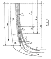
- the axial width L 32 of the first working ply (32) is equal to 0.87 times the maximum axial width S 0 of the average fiber of the carcass reinforcement (1), ie 416 mm, which is, for a tire of usual shape, substantially less than the width L 1 of the tread, which is equal, in the case studied, to 430 mm.
- the axial width L 34 of the second working ply (34) is equal to 0.83 times the axial width S 0 , ie 400 mm.
- the overall axial width L 33 of the additional ply (33) it is equal to 320 mm.
- Said width is decomposed as follows: the central web (33 ') formed of radial cables has a width L' 33 equal to 240 mm, which represents 50% of the width S 0 , each side sheet (33 ") formed of cables circumferential corrugations has an axial width L " 33 equal to 40 mm, the width of a corrugated sheet is measured from peak to peak of the corrugation.
- the final crown ply (35), said protection has a width L substantially equal to 35 370 mm.
- the two working plies (32) and (34) are, on each side of the equatorial plane and axially in the extension of the additional ply (33), coupled over an axial width 1, in this case equal to 15 mm: the cables the first working ply (32) and the cables of the second working ply (34) are separated radially from each other by a layer of rubber, the thickness of which is minimal, over the axial coupling width 1 of the two plies; and corresponds to twice the thickness of the rubbery calendering layer 27.23 wire ropes of which is formed each work sheet (32, 34), 0.8 mm.
- the two working plies (32) and (34) are separated by a profile (4) substantially triangular shaped rubber, the the thickness of said section (4) being increasing from the axial end of the coupling zone to the end of the narrower working ply, to reach a thickness of 4 mm at said end.
- Said section (4) has a width sufficient to radially cover the end of the widest working ply (32), which is, in this case, the working ply radially closest to the carcass reinforcement.
- the crown of the tire is completed by a tread (5) joined to the beads by two flanks (6) and the triangulation ply radially adjacent to the carcass reinforcement (1) on either side of the equatorial plane, away from it axially outwardly, said web being joined to the carcass reinforcement (1) by means of profiles (7) of triangular shaped rubber.
- the second solution tested corresponds to the use, for circumferential reinforcement elements of the lateral parts (33 ") of the additional ply (33), of inextensible steel wire ropes such as the cables used in the working crown plies, but cut in such a way as to have cable sections whose circumferential length is equal to 1/6 of the circumferential length of the ply, said additional ply has, in the case studied, a tangent modulus of elasticity to traction, per unit of width and for a relative elongation of 0.4%, estimated at 3500 daN / mm 2 .
- the third solution corresponds to the use, for circumferential reinforcing elements of the lateral parts (33 ") of the additional ply (33), of non-extensible steel wire ropes such as those used in the working plies, but corrugated, the ratio a / ⁇ of the corrugations, a being the amplitude of undulation and ⁇ its wavelength, being at most equal to 0.09, said ratio allowing a sufficient elongation of said cables in the case of rolling with strong drift while reinforcing satisfactorily the axial portions of the crown reinforcement in the vicinity of the coupling widths between working crown plies.
Landscapes
- Engineering & Computer Science (AREA)
- Mechanical Engineering (AREA)
- Tires In General (AREA)
Claims (11)
- Reifen mit radialer Unterbaubewehrung (1) mit einer maximalen axialen Breite S0, umfassend eine Kronenbewehrung (3), die von mindestens zwei Kronenarbeitslagen (32, 34) von nicht dehnbaren Verstärkungselementen gebildet ist, die von einer Lage (32) zur nächsten (34) gekreuzt sind, wobei sie mit der Umfangsrichtung Winkel zwischen 10° und 45° bilden, wobei die Lagen (32, 34) axiale Breiten L32, L39 mindestens gleich 80 % der Breite S0 aufweisen, wobei eine Zusatzbewehrung (33), die von mindestens einer Lage (33) gebildet ist, umfassend mindestens im Wesentlichen Umfangselemente mit einer Breite L33 kleiner um mindestens 15 % der Breite S0 als die Breite L32 (L34) der schmalsten Arbeitslage, wobei diese radial zwischen den Arbeitslagen (32, 34) angeordnet ist, dadurch gekennzeichnet, dass die Zusatzlage (33) axial aus drei Teilen besteht, einem zentralen Teil in Form einer Lage (33'), die von nicht dehnbaren metallischen und im Wesentlichen radialen Verstärkungselementen gebildet ist, wobei die Lage (33') eine axiale Breite L'33 gleich mindestens 45 % der Breite S0 aufweist, und zwei seitlichen Teilen in Form von Bändern (33"), die jeweils von elastischen metallischen Umfangsverstärkungselementen gebildet sind, wobei das Zugelastizitätsmodul pro Breiteneinheit eines seitlichen Bandes (33") höchstens gleich dem Zugelastizitätsmodul, gemessen unter denselben Bedingungen, der am meisten dehnbaren Arbeitslage (32, 34) ist, und wobei die Breite L"33 jedes Bandes höchstens gleich 10 % der Breite S0 ist.
- Reifen mit radialer Unterbaubewehrung (1) mit einer maximalen axialen Breite S0, umfassend eine Kronenbewehrung (3), die von mindestens zwei Kronenarbeitslagen (32, 34) von nicht dehnbaren Verstärkungselementen gebildet ist, die von einer Lage (32) zur nächsten (34) gekreuzt sind, wobei sie mit der Umfangsrichtung Winkel zwischen 10° und 45° bilden, wobei die Lagen (32, 34) axiale Breiten L32, L39 mindestens gleich 80 % der Breite S0 aufweisen, wobei eine Zusatzbewehrung (33), die von mindestens einer Lage (33) gebildet ist, umfassend mindestens im Wesentlichen Umfangselemente mit einer Breite L33 kleiner um mindestens 15 % der Breite S0 als die Breite L32 (L34) der schmalsten Arbeitslage, wobei diese radial zwischen den Arbeitslagen (32, 34) angeordnet ist, dadurch gekennzeichnet, dass die Zusatzlage (33) axial aus drei Teilen besteht, einem zentralen Teil in Form einer Lage (33'), die von nicht dehnbaren metallischen und im Wesentlichen radialen Verstärkungselementen gebildet ist, wobei die Lage (33') eine axiale Breite L'33 gleich mindestens 45 % der Breite S0 aufweist, und zwei seitlichen Teilen in Form von Bändern (33"), die jeweils von elastischen metallischen Umfangsverstärkungselementen gebildet sind, die derart geschnitten sind, dass sie Abschnitte mit einer geringeren Länge als der Umfang der kürzesten Lage, aber größer als 0,1-mal den Umfang, bilden, wobei die Schnitte zwischen den Abschnitten axial zueinander versetzt sind, wobei das Zugelastizitätsmodul pro Breiteneinheit eines seitlichen Bandes (33") geringer als das Zugelastizitätsmodul, gemessen unter denselben Bedingungen, der am meisten dehnbaren Arbeitslage (32, 34) ist, und wobei die Breite L''33 jedes Bandes höchstens gleich 10 % der Breite S0 ist.
- Reifen mit radialer Unterbaubewehrung (1) mit einer maximalen axialen Breite S0, umfassend eine Kronenbewehrung (3), die von mindestens zwei Kronenarbeitslagen (32, 34) von nicht dehnbaren Verstärkungselementen gebildet ist, die von einer Lage (32) zur nächsten (34) gekreuzt sind, wobei sie mit der Umfangsrichtung Winkel zwischen 10° und 45° bilden, wobei die Lagen (32, 34) axiale Breiten L32, L34 mindestens gleich 80 % der Breite S0 aufweisen, wobei eine Zusatzbewehrung (33), die von mindestens einer Lage (33) gebildet ist, umfassend mindestens im Wesentlichen Umfangselemente mit einer Breite L33 kleiner um mindestens 15 % der Breite S0 als die Breite L32 (L34) der schmalsten Arbeitslage, wobei diese radial zwischen den Arbeitslagen (32, 34) angeordnet ist, dadurch gekennzeichnet, dass die Zusatzlage (33) axial aus drei Teilen besteht, einem zentralen Teil in Form einer Lage (33'), die von nicht dehnbaren metallischen und im Wesentlichen radialen Verstärkungselementen gebildet ist, wobei die Lage (33') eine axiale Breite L'33 gleich mindestens 45 % der Breite S0 aufweist, und zwei seitlichen Teilen in Form von Bändern (33") , die jeweils von nicht dehnbaren und welligen elastischen metallischen Umfangsverstärkungselementen gebildet sind, wobei das Verhältnis a/λ der Wellungsamplitude a zur Wellenlänge λ höchstens gleich 0,09 ist, wobei das Zugelastizitätsmodul pro Breiteneinheit eines seitlichen Bandes (33") geringer als das Zugelastizitätsmodul, gemessen unter denselben Bedingungen, der am meisten dehnbaren Arbeitslage (32, 34) ist, und wobei die Breite L''33 jedes Bandes höchstens gleich 10 % der Breite S0 ist.
- Reifen nach Anspruch 1, dadurch gekennzeichnet, dass die elastischen metallischen Verstärkungselemente der seitlichen Teile (33") der Zusatzlage (33) eine Zugspannungskurve σ in Abhängigkeit von der relativen Verlängerung ε mit geringen Gefällen für die geringen Verlängerungen und einem im Wesentlichen konstanten und starken Gefälle für die größeren Verlängerungen aufweisen, wobei die Änderung des Gefälles in einem Bereich einer relativen Verlängerung zwischen 0,2 % und 0,8 % stattfinden kann.
- Reifen nach Anspruch 1, dadurch gekennzeichnet, dass das Zugmodul jedes seitlichen Teils (33'') einer Zusatzlage (33) derart ist, dass es bei einer relativen Verlängerung zwischen 0 % und 0,4 % gering und höchstens gleich dem höchsten Zugelastizitätsmodul der am meisten dehnbaren Arbeitslage (32, 34) bei relativen Verlängerungen über 0,4 % ist.
- Reifen nach einem der Ansprüche 1 bis 5, dadurch gekennzeichnet, dass die nicht dehnbaren Verstärkungselemente der Lagen (32, 34, 33') vorzugsweise metallische Stahlkabel sind.
- Reifen nach einem der Ansprüche 1 bis 5, dadurch gekennzeichnet, dass die Arbeitslagen (32, 34) beiderseits der Äquatorialebene und in der unmittelbaren axialen Verlängerung der Zusatzbewehrung (33) auf einem axialen Abstand 1 mindestens gleich 3,5% der Breite S0 gekoppelt sind, um dann durch Profile (4) aus Kautschukgemisch mindestens auf der restlichen gemeinsamen Breite der beiden Arbeitslagen (32, 34) entkoppelt zu sein.
- Reifen nach einem der Ansprüche 1 bis 5, dadurch gekennzeichnet, dass die Kronenbewehrung (3) radial außen durch mindestens eine Zusatzlage (35), Schutzlage genannt, von so genannten elastischen Verstärkungselementen ergänzt ist, die zur Umfangsrichtung in einem Winkel zwischen 10° und 45° mit derselben Ausrichtung wie der Winkel, der von den nicht dehnbaren Elementen der Arbeitslage (32, 34), die an sie radial angrenzt, gebildet ist, ausgerichtet sind.
- Reifen nach Anspruch 8, dadurch gekennzeichnet, dass die elastischen Verstärkungselemente der Schutzlage(n) (35) metallische Stahlkabel sind.
- Reifen nach Anspruch 8, dadurch gekennzeichnet, dass die Schutzlage (35) eine größere axiale Breite L35 als de axiale Breite der schmalsten radial oberen Arbeitslage (34) hat, so dass sie die Ränder der schmalsten Arbeitslage abdeckt und in der axialen Verlängerung der Zusatzbewehrung (33) mit der breitesten Kronenarbeitslage (32) auf einem axialen Abstand mindestens gleich 2 % der Breite S0 gekoppelt ist, um dann axial außerhalb von der breitesten Arbeitslage (32) durch Profile mit einer Dicke mindestens gleich 2 mm entkoppelt zu werden.
- Reifen nach einem der Ansprüche 1 bis 5, dadurch gekennzeichnet, dass die Kronenbewehrung (3) radial innen zwischen der Unterbaubewehrung (1) und der radial inneren Arbeitslage (32), die der Unterbaubewehrung (1) am nächsten ist, von einer Triangulationslage von nicht dehnbaren metallischen Verstärkungselementen aus Stahl ergänzt ist, die mit der Umfangsrichtung einen Winkel über 60° bilden, der dieselbe Ausrichtung wie jene des Winkels hat, der von den Verstärkungselementen der radial zur Unterbaubewehrung (1) nächsten Lage (32) gebildet wird.
Applications Claiming Priority (1)
| Application Number | Priority Date | Filing Date | Title |
|---|---|---|---|
| PCT/FR1999/001160 WO2000069659A1 (fr) | 1999-05-14 | 1999-05-14 | Armature de sommet pour pneumatique radial |
Publications (2)
| Publication Number | Publication Date |
|---|---|
| EP1189769A1 EP1189769A1 (de) | 2002-03-27 |
| EP1189769B1 true EP1189769B1 (de) | 2008-08-20 |
Family
ID=9541486
Family Applications (1)
| Application Number | Title | Priority Date | Filing Date |
|---|---|---|---|
| EP99919332A Expired - Lifetime EP1189769B1 (de) | 1999-05-14 | 1999-05-14 | Verstärkungsgürtel für einen radialreifen |
Country Status (10)
| Country | Link |
|---|---|
| US (1) | US6612353B2 (de) |
| EP (1) | EP1189769B1 (de) |
| JP (1) | JP4309067B2 (de) |
| KR (1) | KR100631312B1 (de) |
| CN (1) | CN1275785C (de) |
| BR (1) | BR9917531A (de) |
| CA (1) | CA2370909C (de) |
| DE (1) | DE69939402D1 (de) |
| HU (1) | HU223234B1 (de) |
| WO (1) | WO2000069659A1 (de) |
Families Citing this family (24)
| Publication number | Priority date | Publication date | Assignee | Title |
|---|---|---|---|---|
| FR2778368A1 (fr) * | 1998-05-11 | 1999-11-12 | Michelin & Cie | Armature de sommet de pneumatique |
| EP1403096B1 (de) * | 2001-03-16 | 2006-02-08 | Bridgestone Corporation | Luftreifen |
| WO2003101714A2 (fr) * | 2002-06-03 | 2003-12-11 | Societe De Technologie Michelin | Fabrication d’une structure de renforcement pour pneumatique avec controle volumetrique de la matrice |
| ES2333722T3 (es) * | 2003-07-18 | 2010-02-26 | Societe De Technologie Michelin | Neumatico para vehiculos pesados. |
| FR2857620B1 (fr) * | 2003-07-18 | 2005-08-19 | Michelin Soc Tech | Pneumatique pour vehicules lourds |
| JP4397207B2 (ja) * | 2003-10-06 | 2010-01-13 | 株式会社ブリヂストン | 空気入りラジアルタイヤ |
| US6935393B2 (en) * | 2003-10-23 | 2005-08-30 | The Goodyear Tire & Rubber Company | Tire having an overlay for noise improvement |
| FR2870163B1 (fr) * | 2004-05-13 | 2007-09-14 | Michelin Soc Tech | Pneumatique pour vehicules lourds |
| JP4572651B2 (ja) * | 2004-10-18 | 2010-11-04 | 横浜ゴム株式会社 | 空気入りタイヤ |
| FR2887816A1 (fr) * | 2005-06-30 | 2007-01-05 | Michelin Soc Tech | Pneumatique pour vehicules lourds |
| JP4964949B2 (ja) * | 2006-10-13 | 2012-07-04 | ソシエテ ド テクノロジー ミシュラン | 改良された剪断バンド |
| JP4743126B2 (ja) * | 2007-01-23 | 2011-08-10 | 横浜ゴム株式会社 | 空気入りラジアルタイヤ |
| FR2916159B1 (fr) * | 2007-05-14 | 2011-03-18 | Michelin Soc Tech | Pneumatique pour vehicules lourds |
| FR2916160B1 (fr) * | 2007-05-14 | 2009-07-17 | Michelin Soc Tech | Pneumatique pour vehicules lourds |
| EP2168787B1 (de) * | 2007-06-28 | 2013-09-04 | Bridgestone Corporation | Luftreifen |
| JP4978351B2 (ja) * | 2007-07-10 | 2012-07-18 | 横浜ゴム株式会社 | 空気入りタイヤ |
| FR2921015B1 (fr) * | 2007-09-13 | 2011-04-15 | Michelin Soc Tech | Pneumatique pour vehicules lourds. |
| FR2921014B1 (fr) | 2007-09-13 | 2011-03-18 | Michelin Soc Tech | Pneumatique pour vehicules lourds. |
| JP4849050B2 (ja) * | 2007-10-24 | 2011-12-28 | 横浜ゴム株式会社 | 空気入りタイヤ |
| JP5275655B2 (ja) * | 2008-03-25 | 2013-08-28 | 株式会社ブリヂストン | 空気入りタイヤ |
| DE102010016550A1 (de) | 2010-04-21 | 2011-10-27 | Continental Reifen Deutschland Gmbh | Fahrzeugluftreifen |
| DE102011001228A1 (de) * | 2011-03-11 | 2012-09-13 | Continental Reifen Deutschland Gmbh | Fahrzeugluftreifen |
| FR2999985B1 (fr) * | 2012-12-20 | 2017-02-03 | Michelin & Cie | Sommet de pneumatique pour vehicule lourd de type genie civil |
| FR2999984B1 (fr) * | 2012-12-20 | 2016-02-12 | Michelin & Cie | Sommet de pneumatique pour vehicule lourd de type genie civil |
Family Cites Families (11)
| Publication number | Priority date | Publication date | Assignee | Title |
|---|---|---|---|---|
| US3999586A (en) | 1974-04-18 | 1976-12-28 | The General Tire & Rubber Company | Reinforcing belt for a pneumatic tire |
| FR2379391A1 (fr) | 1977-02-07 | 1978-09-01 | Uniroyal | Nouvelle ceinture de renforcement d'enveloppe de bandage pneumatique pour roue de vehicule automobile et enveloppe en comportant application |
| FR2473426A1 (fr) * | 1979-12-06 | 1981-07-17 | Dunlop Ltd | Pneumatique a ceinture de renforcement, notamment pour poids lourds |
| IT1204980B (it) * | 1987-04-28 | 1989-03-10 | Pirelli | Miglioramenti alle armature di rinforzo dei pneumatici per ruote di veicoli |
| US5054532A (en) * | 1989-02-06 | 1991-10-08 | Bridgestone Corporation | Pneumatic tires with wavy or zigzag cord ply between belt and carcass |
| FR2719257B1 (fr) * | 1994-04-28 | 1996-07-19 | Dunlop Sa | Pneumatique radial renforcé pour poids lourd. |
| FR2728510A1 (fr) | 1994-12-23 | 1996-06-28 | Michelin & Cie | Pneumatique de rapport de forme h/s inferieur ou egal a 0,6 |
| FR2754769B1 (fr) * | 1996-10-23 | 1998-12-11 | Michelin & Cie | Armature de sommet pour pneumatique "poids-lourds" de rapport de forme < 0,60 |
| FR2770458B1 (fr) * | 1997-11-05 | 1999-12-03 | Michelin & Cie | Armature de sommet pour pneumatique "poids-lours" |
| FR2778368A1 (fr) | 1998-05-11 | 1999-11-12 | Michelin & Cie | Armature de sommet de pneumatique |
| FR2778370B1 (fr) * | 1998-05-11 | 2000-06-16 | Michelin & Cie | Armature de sommet de pneumatique radial |
-
1999
- 1999-05-14 JP JP2000618098A patent/JP4309067B2/ja not_active Expired - Fee Related
- 1999-05-14 EP EP99919332A patent/EP1189769B1/de not_active Expired - Lifetime
- 1999-05-14 KR KR1020017014435A patent/KR100631312B1/ko not_active IP Right Cessation
- 1999-05-14 HU HU0201169A patent/HU223234B1/hu not_active IP Right Cessation
- 1999-05-14 CA CA002370909A patent/CA2370909C/fr not_active Expired - Fee Related
- 1999-05-14 CN CNB998166456A patent/CN1275785C/zh not_active Expired - Lifetime
- 1999-05-14 WO PCT/FR1999/001160 patent/WO2000069659A1/fr active IP Right Grant
- 1999-05-14 BR BR9917531-2A patent/BR9917531A/pt not_active IP Right Cessation
- 1999-05-14 DE DE69939402T patent/DE69939402D1/de not_active Expired - Lifetime
-
2001
- 2001-11-14 US US09/993,029 patent/US6612353B2/en not_active Expired - Lifetime
Also Published As
| Publication number | Publication date |
|---|---|
| DE69939402D1 (de) | 2008-10-02 |
| CA2370909C (fr) | 2008-09-30 |
| US6612353B2 (en) | 2003-09-02 |
| EP1189769A1 (de) | 2002-03-27 |
| HUP0201169A2 (en) | 2002-08-28 |
| CA2370909A1 (fr) | 2000-11-23 |
| KR100631312B1 (ko) | 2006-10-09 |
| WO2000069659A1 (fr) | 2000-11-23 |
| JP2002544044A (ja) | 2002-12-24 |
| HU223234B1 (hu) | 2004-04-28 |
| CN1350495A (zh) | 2002-05-22 |
| US20020033213A1 (en) | 2002-03-21 |
| BR9917531A (pt) | 2004-10-19 |
| KR20020012217A (ko) | 2002-02-15 |
| JP4309067B2 (ja) | 2009-08-05 |
| CN1275785C (zh) | 2006-09-20 |
Similar Documents
| Publication | Publication Date | Title |
|---|---|---|
| EP1189769B1 (de) | Verstärkungsgürtel für einen radialreifen | |
| CA2308037C (fr) | Armature de sommet pour pneumatique "poids-lourds" | |
| EP1750954B1 (de) | Schwerfahrzeugreifen | |
| EP0963301B1 (de) | Reifen mit höhe-zu-breiteverhältnis, das kleiner als oder gleich 0,6 ist | |
| EP1597094B1 (de) | Gürtelverstärkung für einen radialreifen | |
| EP1035978B1 (de) | Reifengürtel | |
| EP0799140A1 (de) | Reifen mit einem höhe-zu-breiteverhältniss, das nicht grösser als 0,6 ist | |
| EP0883503B1 (de) | Verstärkungsgürtel, insbesondere für lkw-reifen | |
| WO1996025297A1 (fr) | Armature de sommet pour pneumatique radial | |
| EP1077815B1 (de) | Verstärkungsgürtel von radialen reifen | |
| EP1163120B1 (de) | Verstärkungsgürtel für radialen reifen | |
| CA2611085A1 (fr) | Pneumatique pour vehicules lourds | |
| EP0999939B1 (de) | Reifengürtel | |
| EP3390076B1 (de) | Reifen mit verbesserten abnutzungseigenschaften | |
| CA2610765A1 (fr) | Pneumatique pour vehicules lourds | |
| EP3390079B1 (de) | Reifen mit verbesserten abnutzungseigenschaften | |
| FR3045492A1 (fr) | Pneumatique presentant des proprietes d'usure ameliorees | |
| WO2000071366A1 (fr) | Bourrelet sans tringle pour pneumatique | |
| EP3390078B1 (de) | Reifen mit verbesserten abnutzungseigenschaften | |
| WO2014191307A1 (fr) | Pneumatique pour vehicules lourds comportant une armature de sommet renforcee |
Legal Events
| Date | Code | Title | Description |
|---|---|---|---|
| PUAI | Public reference made under article 153(3) epc to a published international application that has entered the european phase |
Free format text: ORIGINAL CODE: 0009012 |
|
| 17P | Request for examination filed |
Effective date: 20011214 |
|
| AK | Designated contracting states |
Kind code of ref document: A1 Designated state(s): DE ES FR GB IT |
|
| GRAP | Despatch of communication of intention to grant a patent |
Free format text: ORIGINAL CODE: EPIDOSNIGR1 |
|
| GRAS | Grant fee paid |
Free format text: ORIGINAL CODE: EPIDOSNIGR3 |
|
| GRAA | (expected) grant |
Free format text: ORIGINAL CODE: 0009210 |
|
| RAP1 | Party data changed (applicant data changed or rights of an application transferred) |
Owner name: MICHELIN RECHERCHE ET TECHNIQUE S.A. Owner name: SOCIETE DE TECHNOLOGIE MICHELIN |
|
| AK | Designated contracting states |
Kind code of ref document: B1 Designated state(s): DE ES FR GB IT |
|
| REG | Reference to a national code |
Ref country code: GB Ref legal event code: FG4D Free format text: NOT ENGLISH |
|
| REF | Corresponds to: |
Ref document number: 69939402 Country of ref document: DE Date of ref document: 20081002 Kind code of ref document: P |
|
| PG25 | Lapsed in a contracting state [announced via postgrant information from national office to epo] |
Ref country code: ES Free format text: LAPSE BECAUSE OF FAILURE TO SUBMIT A TRANSLATION OF THE DESCRIPTION OR TO PAY THE FEE WITHIN THE PRESCRIBED TIME-LIMIT Effective date: 20081201 |
|
| PLBE | No opposition filed within time limit |
Free format text: ORIGINAL CODE: 0009261 |
|
| STAA | Information on the status of an ep patent application or granted ep patent |
Free format text: STATUS: NO OPPOSITION FILED WITHIN TIME LIMIT |
|
| 26N | No opposition filed |
Effective date: 20090525 |
|
| GBPC | Gb: european patent ceased through non-payment of renewal fee |
Effective date: 20090514 |
|
| PG25 | Lapsed in a contracting state [announced via postgrant information from national office to epo] |
Ref country code: GB Free format text: LAPSE BECAUSE OF NON-PAYMENT OF DUE FEES Effective date: 20090514 |
|
| PGFP | Annual fee paid to national office [announced via postgrant information from national office to epo] |
Ref country code: IT Payment date: 20120529 Year of fee payment: 14 |
|
| PG25 | Lapsed in a contracting state [announced via postgrant information from national office to epo] |
Ref country code: IT Free format text: LAPSE BECAUSE OF NON-PAYMENT OF DUE FEES Effective date: 20130514 |
|
| REG | Reference to a national code |
Ref country code: FR Ref legal event code: PLFP Year of fee payment: 18 |
|
| REG | Reference to a national code |
Ref country code: FR Ref legal event code: PLFP Year of fee payment: 19 |
|
| REG | Reference to a national code |
Ref country code: FR Ref legal event code: PLFP Year of fee payment: 20 |
|
| PGFP | Annual fee paid to national office [announced via postgrant information from national office to epo] |
Ref country code: DE Payment date: 20180522 Year of fee payment: 20 |
|
| PGFP | Annual fee paid to national office [announced via postgrant information from national office to epo] |
Ref country code: FR Payment date: 20180522 Year of fee payment: 20 |
|
| REG | Reference to a national code |
Ref country code: DE Ref legal event code: R071 Ref document number: 69939402 Country of ref document: DE |