EP1898093A1 - Dispositif de pompe - Google Patents
Dispositif de pompe Download PDFInfo
- Publication number
- EP1898093A1 EP1898093A1 EP07016273A EP07016273A EP1898093A1 EP 1898093 A1 EP1898093 A1 EP 1898093A1 EP 07016273 A EP07016273 A EP 07016273A EP 07016273 A EP07016273 A EP 07016273A EP 1898093 A1 EP1898093 A1 EP 1898093A1
- Authority
- EP
- European Patent Office
- Prior art keywords
- diaphragm
- control
- pressure
- pump head
- pump
- Prior art date
- Legal status (The legal status is an assumption and is not a legal conclusion. Google has not performed a legal analysis and makes no representation as to the accuracy of the status listed.)
- Granted
Links
- 238000005086 pumping Methods 0.000 title claims description 8
- 239000012530 fluid Substances 0.000 claims abstract description 75
- 239000012528 membrane Substances 0.000 claims description 42
- 239000002184 metal Substances 0.000 claims description 8
- 239000004033 plastic Substances 0.000 claims description 5
- 239000004810 polytetrafluoroethylene Substances 0.000 claims description 3
- 229920001343 polytetrafluoroethylene Polymers 0.000 claims description 3
- 230000011664 signaling Effects 0.000 claims description 3
- 230000008878 coupling Effects 0.000 claims description 2
- 238000010168 coupling process Methods 0.000 claims description 2
- 238000005859 coupling reaction Methods 0.000 claims description 2
- 230000003068 static effect Effects 0.000 claims description 2
- XLYOFNOQVPJJNP-UHFFFAOYSA-N water Substances O XLYOFNOQVPJJNP-UHFFFAOYSA-N 0.000 claims description 2
- 238000000034 method Methods 0.000 abstract description 3
- 239000007787 solid Substances 0.000 description 4
- 238000006073 displacement reaction Methods 0.000 description 3
- 238000010276 construction Methods 0.000 description 2
- 238000001816 cooling Methods 0.000 description 2
- 239000000463 material Substances 0.000 description 2
- 238000011144 upstream manufacturing Methods 0.000 description 2
- 230000000712 assembly Effects 0.000 description 1
- 238000000429 assembly Methods 0.000 description 1
- 230000005540 biological transmission Effects 0.000 description 1
- 239000010796 biological waste Substances 0.000 description 1
- 230000000903 blocking effect Effects 0.000 description 1
- 230000001627 detrimental effect Effects 0.000 description 1
- 230000000694 effects Effects 0.000 description 1
- 230000005484 gravity Effects 0.000 description 1
- 230000001771 impaired effect Effects 0.000 description 1
- 239000000203 mixture Substances 0.000 description 1
- 230000002093 peripheral effect Effects 0.000 description 1
- 230000002265 prevention Effects 0.000 description 1
- 238000011084 recovery Methods 0.000 description 1
- 239000000725 suspension Substances 0.000 description 1
Images
Classifications
-
- F—MECHANICAL ENGINEERING; LIGHTING; HEATING; WEAPONS; BLASTING
- F04—POSITIVE - DISPLACEMENT MACHINES FOR LIQUIDS; PUMPS FOR LIQUIDS OR ELASTIC FLUIDS
- F04B—POSITIVE-DISPLACEMENT MACHINES FOR LIQUIDS; PUMPS
- F04B43/00—Machines, pumps, or pumping installations having flexible working members
- F04B43/02—Machines, pumps, or pumping installations having flexible working members having plate-like flexible members, e.g. diaphragms
- F04B43/025—Machines, pumps, or pumping installations having flexible working members having plate-like flexible members, e.g. diaphragms two or more plate-like pumping members in parallel
- F04B43/026—Machines, pumps, or pumping installations having flexible working members having plate-like flexible members, e.g. diaphragms two or more plate-like pumping members in parallel each plate-like pumping flexible member working in its own pumping chamber
-
- F—MECHANICAL ENGINEERING; LIGHTING; HEATING; WEAPONS; BLASTING
- F04—POSITIVE - DISPLACEMENT MACHINES FOR LIQUIDS; PUMPS FOR LIQUIDS OR ELASTIC FLUIDS
- F04B—POSITIVE-DISPLACEMENT MACHINES FOR LIQUIDS; PUMPS
- F04B43/00—Machines, pumps, or pumping installations having flexible working members
- F04B43/02—Machines, pumps, or pumping installations having flexible working members having plate-like flexible members, e.g. diaphragms
- F04B43/06—Pumps having fluid drive
- F04B43/067—Pumps having fluid drive the fluid being actuated directly by a piston
Definitions
- the invention relates to a pump device with a first diaphragm pump head and a second diaphragm pump head hydraulically coupled thereto.
- piston pumps For the promotion or recirculation of viscous media with high solids content (suspensions) at high pressures of over 200 bar and high temperature of over 300 ° C piston pumps can be used. However, they are suitable for such an application only limited, since the solids fractions in a relatively short time destroy associated seals a piston and cause scoring on a surface of the piston.
- plastic membranes for example made of PTFE
- metal membranes is possible in principle, but technical requirements such as multi-layer membrane with fracture signaling and a design as a freely oscillating in the product space membrane with layer control can be realized only with great effort, see EP 0 085 725 A1 ,
- the high pressure of the fluid to be pumped leads to another problem.
- the piston rod force of reciprocating displacement pumps resulting from the product of pressure and area may require the use of very large pump drive assemblies which may be uneconomical for the required application in two respects. On the one hand, this entails considerably higher investment costs and, on the other hand, higher life-cycle costs, which can be characterized in particular by energy costs and expenditures for wear and spare parts.
- the economic consideration of pump systems for recirculation with the boundary conditions mentioned above is of particular importance in processes for energy recovery from biological waste.
- the pump device comprises a first diaphragm pump head with two or an integer multiple of two fluid delivery chambers and associated membranes, which are hydraulically coupled to a second diaphragm pump head, wherein the second diaphragm pump head has two additional fluid delivery chambers and associated additional membranes that of a double-acting piston can be driven via associated diaphragm control chambers, wherein in each case a refill valve is connected to the diaphragm control chambers and the membrane control chambers are temporarily acted upon by the Nach Glallventile with a membrane pressure which is greater than atmospheric pressure.
- Such a pumping device is advantageous in that, at a time when the refill valves top up the diaphragm control chambers with a control fluid to compensate for unavoidable leakage of the control fluid, a short-term pressure drop in the diaphragm control chambers, which has hitherto been common in position-controlled diaphragms, up to atmospheric pressure through the diaphragm control chambers superimposed diaphragm control pressure which is greater than the atmospheric pressure can be limited.
- the pump device is configured such that the diaphragm control pressure corresponds approximately to a fluid pressure at the inlet of a fluid delivery chamber of the first diaphragm pump head.
- This allows almost complete compensation of the described short-term pressure drop in the diaphragm control chamber of the second diaphragm pump head.
- the drive unit for the piston only has to be designed for forces which correspond approximately to the pressure difference between the inlet and the outlet of a fluid delivery chamber of the first diaphragm pump head.
- the membrane control pressure can preferably be adapted to the fluid pressure by means of a control loop with associated sensors and actuators. Especially with an electronic control circuit this allows an optimally coordinated Compensation of the described pressure drop and thus the prevention of pressure surges, which can exert a detrimental effect on the drive unit.
- the membrane control pressure may be generated by a pump which is coupled to a respective container for a diaphragm control chamber, each container having one of the refill valves and each container is acted upon by the pump with a static back pressure.
- the pump is permanently in operation.
- the membrane control pressure can be generated by a controllable pump which feeds a pressure accumulator, which is in each case coupled to a container for a diaphragm control chamber.
- the container serves as a refill reservoir in this case.
- the pump is only in operation when a predetermined lower limit pressure in the accumulator is exceeded. The pump then operates until an upper limit pressure is reached again in the accumulator (two-step control).
- a respective container as a refill reservoir of a control fluid for a diaphragm control chamber of the second diaphragm pump head, wherein each container an adjustable throttle device is connected downstream.
- the pump can be constantly in operation, so that a continuous circulation of a control fluid is given.
- the structure of the pumping device and its operation is relatively symmetrical when the piston is designed as a double-acting disc piston with opposing piston rods.
- the piston surfaces on both sides of the disc piston have an identical size, so that during a suction stroke or pressure stroke in each case the same pressure change and the same volume displacement is generated.
- the membranes of the first diaphragm pump head are each free-swinging metal membranes, due to the material metal, a fluid can be transported at high temperatures. Since the first diaphragm pump head and the second diaphragm pump head are coupled via lines with a control fluid, these lines can act as cooling sections.
- the membranes of the second diaphragm pump head may be formed of a plastic, in particular PTFE, so that none There is a risk that these plastic membranes show a significant flow because of too high a temperature.
- the membranes of the second diaphragm pump head each have a multi-layered design and are provided with a position control and breakage signaling, the safety during conveying of the fluid can be increased.
- An even higher level of safety is achieved if a conductivity or viscosity sensor is provided within the diaphragm control chambers of the first diaphragm pump head. Should a metal diaphragm break in the first diaphragm pump head, the fluid to be delivered could enter the adjacent diaphragm control chambers, so that a mixing of delivery fluid and control fluid would occur. Such mixing may alter the electrical conductivity or viscosity of the mixture as compared to the values of the control fluid so that the sensor can detect a break in a metal membrane.
- the hydraulic coupling between the first diaphragm pump head and the second diaphragm pump head may be by means of control fluids comprising water or oil.
- control fluids comprising water or oil.
- oil for example, a special heat transfer oil can be used when the pumping device is used to convey a fluid at high temperatures.
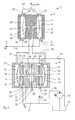
- the bulging of the membrane 3 is effected by the application of a pressure in the first diaphragm control chamber 5. If there is applied by dp higher pressure, there is a pressure p1 + dp at the pressure valve 62, with which the fluid is transported to the discharge line 63.
- the pressure p1 + dp is provided by a first conduit 13 from a second diaphragm pump head 8.
- This has a second membrane 9, which separates a second fluid delivery chamber 10 from a second diaphragm control chamber 11.
- the second fluid delivery chamber 10 is coupled to the first diaphragm control chamber 5 by a first control fluid 12.
- this first control fluid 12 is passed through the first line 13 to the first diaphragm control chamber 5, so that the first diaphragm 3 bulges.
- Such a displacement of the first control fluid 12 is achieved by means of a piston 15, which exerts a stroke, which is directed downward in the embodiment shown in Fig. 1.
- the stroke movement of the disk piston 31 in a direction pointing downwards in the embodiment shown in FIG. 1 is effected by a pump drive unit 51 by means of a first piston rod 33.
- a second piston rod 35 is arranged opposite to the first piston rod 33.
- the disk piston 31 is constructed symmetrically, so that on both opposite end faces of the disk piston 31, the same area is present. This has the consequence that in a piston stroke in the lower piston chamber 32, the same amount of pressure and volume change is achieved as in a piston stroke in an opposite upper piston chamber 34th
- the upper piston chamber 34 is part of a third diaphragm control chamber 17 which is separated from a third fluid delivery chamber 19 by a third diaphragm 18.
- the transfer medium used is a third control fluid 16 in the third diaphragm control chamber 17.
- the pressure p1 alternately across the membranes 3 and 24, the control fluids 12 and 21, the membranes 9 and 18 and the control fluids 14 and 16 respectively on the piston chamber 32 and 34 executing the suction stroke transfer.
- a short-term pressure drop to atmospheric pressure takes place in the respective diaphragm control chamber.
- a pressure p2 is then superimposed on the pressure present in the diaphragm control chambers 11 and 17, so that the pressure reduction can be compensated.
- the pressure p2 is provided by a pump 50 via a supply line 36 to the containers 37 and 39. In the case of the refilling process controlled by the membrane position, the pressure p2 is forwarded into the membrane control chambers 11 and 17. Excess control fluid is discharged via a vent valve 42 and 44 into a container 41 and 43, respectively, and conducted by means of a return line 53 into a control fluid reservoir 52.
- the upper piston space 34 is increased, so that the third diaphragm 18 is compressed.
- This also increases the volume of the third fluid delivery chamber 19, which is coupled via a fourth control fluid 21 and the second conduit 22 to a fourth diaphragm control chamber 23.
- the fourth diaphragm control chamber 23 is located in the embodiment shown in FIG. 1 in the first diaphragm control head 2 and is separated by a fourth diaphragm 24 from a fourth fluid conveying chamber 25.
- This structure is a mirror image of the structure with the first membrane 3, the first fluid conveying chamber 4 and the first diaphragm control chamber 5.
- the volume of the fourth fluid delivery chamber 25 is increased, so that a suction or a fluid supply via the inlet opening 26 takes place with the suction valve 64. If the disc piston is moved in an upward stroke, the conditions described above are reversed. Then, the fourth fluid delivery chamber 25 conveys a fluid through an outlet port 28 by means of a vent valve 65 into a discharge line 63, while the first fluid delivery chamber 4 is filled.
- the first membrane 3 and fourth membrane 24 are free-swinging metal membranes. On a multi-layer design and a membrane layer control can be omitted. A check as to whether a breakage of a metal membrane has occurred can be made indirectly by means of a conductivity or viscosity sensor 29 or 30. At a break of e.g. the membrane 3, there is a mixing of the fluids in the first fluid conveying space 4 and the first diaphragm control chamber 5, so that the electrical conductance or the viscosity changes, which can be detected by the sensors 29 or 30.
- the third diaphragm 18 is compressed in the pump device in the second diaphragm pump head 8 during a suction stroke of the disc piston 31 in such a way that it reaches its rear end, the pressure in the third diaphragm control chamber 17 can drop to below or below the atmospheric pressure, as mentioned above , This is undesirable, since in this case a significant increase in the thrust force of the piston 15 occurs abruptly and the pump drive unit is heavily loaded. In the case of the pump device according to the invention, this can be avoided by the permanent pressurization with p2, which corresponds approximately to p1, via the containers 37 and 39.
- the second diaphragm pump head 8 for the respective second 9 and third diaphragm 18 has a separate diaphragm position control, as described in US Pat EP 0 085 725 A1 is disclosed.
- the respective refill valves 38 and 40 are replaced by a spring-mounted control plunger, which has a region with a conical surface screwed into its circumferential surface, and a tumbling rod operatively connected therewith, which in turn releases or blocks a spring-loaded refill valve.
- a spring-mounted support plate secured against falling out in the direction of the respective diaphragm 18 or 9 and provided with passage openings for the respective control fluid 16 or 14 is arranged, which is in operative connection with the control tappet.
- Has a loss give the control fluid 16 and 14, so shifts the respective towards the diaphragm control chamber 17 and 11 directed end position of the diaphragm 18 and 9, so that the support plate against the spring force supporting them and against the plunger supporting spring force is moved.
- the movement of the support plate thus moves the control plunger, so that its conical peripheral region releases the tumbler, which, for example, falls by gravity in the direction of the control plunger longitudinal axis.
- a spring force the tumbler in the direction of the control plunger is released by the tumbler, so that due to the pressure prevailing in the diaphragm control chamber 17 and 11 negative pressure, the refill is opened against the supporting spring force and the control fluid 16 and 14 can flow into the respective diaphragm control chamber 17 and 11 respectively.
- the previously shifted end position of the affected membrane moves back 18 or 9 in the correct end position and thus again releases the support plate which releases the control plunger and thus the tumbler bar pushes back into the blocking position, whereby the valve is locked, which is also closed by the pressure balance due to its supporting spring again.
Landscapes
- Engineering & Computer Science (AREA)
- Mechanical Engineering (AREA)
- General Engineering & Computer Science (AREA)
- Reciprocating Pumps (AREA)
- Eye Examination Apparatus (AREA)
- Electrical Discharge Machining, Electrochemical Machining, And Combined Machining (AREA)
- Polarising Elements (AREA)
- Fluid-Driven Valves (AREA)
- Seal Device For Vehicle (AREA)
Priority Applications (2)
| Application Number | Priority Date | Filing Date | Title |
|---|---|---|---|
| DK09009999.5T DK2108838T3 (da) | 2006-09-04 | 2007-08-20 | Pumpeindretning |
| EP09009999A EP2108838B1 (fr) | 2006-09-04 | 2007-08-20 | Dispositif de pompe |
Applications Claiming Priority (1)
| Application Number | Priority Date | Filing Date | Title |
|---|---|---|---|
| DE102006041420A DE102006041420A1 (de) | 2006-09-04 | 2006-09-04 | Pumpenvorrichtung |
Related Child Applications (1)
| Application Number | Title | Priority Date | Filing Date |
|---|---|---|---|
| EP09009999A Division EP2108838B1 (fr) | 2006-09-04 | 2007-08-20 | Dispositif de pompe |
Publications (2)
| Publication Number | Publication Date |
|---|---|
| EP1898093A1 true EP1898093A1 (fr) | 2008-03-12 |
| EP1898093B1 EP1898093B1 (fr) | 2009-08-05 |
Family
ID=38691113
Family Applications (2)
| Application Number | Title | Priority Date | Filing Date |
|---|---|---|---|
| EP07016273A Active EP1898093B1 (fr) | 2006-09-04 | 2007-08-20 | Dispositif de pompe |
| EP09009999A Active EP2108838B1 (fr) | 2006-09-04 | 2007-08-20 | Dispositif de pompe |
Family Applications After (1)
| Application Number | Title | Priority Date | Filing Date |
|---|---|---|---|
| EP09009999A Active EP2108838B1 (fr) | 2006-09-04 | 2007-08-20 | Dispositif de pompe |
Country Status (8)
| Country | Link |
|---|---|
| US (2) | US8360750B2 (fr) |
| EP (2) | EP1898093B1 (fr) |
| JP (2) | JP5221085B2 (fr) |
| AT (2) | ATE547631T1 (fr) |
| CA (1) | CA2599949C (fr) |
| DE (3) | DE102006041420A1 (fr) |
| DK (2) | DK2108838T3 (fr) |
| ES (1) | ES2331030T3 (fr) |
Cited By (2)
| Publication number | Priority date | Publication date | Assignee | Title |
|---|---|---|---|---|
| EP2154371A1 (fr) | 2008-08-14 | 2010-02-17 | Bran + Lübbe GmbH | Dispositif de pompe |
| DE202008010872U1 (de) | 2008-08-14 | 2010-02-25 | Bran+Luebbe Gmbh | Pumpenvorrichtung |
Families Citing this family (13)
| Publication number | Priority date | Publication date | Assignee | Title |
|---|---|---|---|---|
| US8955491B2 (en) * | 2005-03-09 | 2015-02-17 | Merton W. Pekrul | Rotary engine vane head method and apparatus |
| US8197231B2 (en) | 2005-07-13 | 2012-06-12 | Purity Solutions Llc | Diaphragm pump and related methods |
| EP2531729B1 (fr) * | 2010-02-02 | 2020-03-04 | Dajustco Ip Holdings Inc. | Pompe à diaphragme avec système de commande de fluide hydraulique |
| US9610392B2 (en) | 2012-06-08 | 2017-04-04 | Fresenius Medical Care Holdings, Inc. | Medical fluid cassettes and related systems and methods |
| DE102013207193A1 (de) * | 2013-04-22 | 2014-10-23 | Robert Bosch Gmbh | Mikrohydraulisches System, insbesondere zum Einsatz in planaren Mikrofluidiklaboren |
| CN103277289A (zh) * | 2013-05-10 | 2013-09-04 | 北京京城压缩机有限公司 | 一种具有单缸体双缸盖的隔膜式压缩机集成缸体部件 |
| US9845794B2 (en) | 2013-10-08 | 2017-12-19 | Ingersoll-Rand Company | Hydraulically actuated diaphragm pumps |
| EP3115607B1 (fr) * | 2015-07-10 | 2018-02-21 | J. Wagner AG | Pompe a double membrane |
| US12004329B1 (en) * | 2017-08-28 | 2024-06-04 | Equinix, Inc. | Data center refrigeration system |
| KR102167568B1 (ko) * | 2020-03-11 | 2020-10-20 | 톈진 나가르 메커니컬 인더스트리 리미티드 컴퍼니 | 고압 플런저 방식 더블 다이아프램 펌프 |
| WO2021211463A1 (fr) * | 2020-04-13 | 2021-10-21 | S.P.M. Flow Control, Inc. | Système de pompage ayant des blocs vannes distants |
| KR20230101838A (ko) * | 2020-11-09 | 2023-07-06 | 피디씨 머신즈 인크. | 유압 구동식 다이어프램 컴프레서 시스템 |
| US11867169B2 (en) | 2021-11-08 | 2024-01-09 | Pdc Machines, Inc. | High-throughput diaphragm compressor |
Citations (3)
| Publication number | Priority date | Publication date | Assignee | Title |
|---|---|---|---|---|
| US3630642A (en) * | 1970-02-03 | 1971-12-28 | Du Pont | Diaphragm pump |
| EP0011022A1 (fr) * | 1978-10-27 | 1980-05-14 | COMMISSARIAT A L'ENERGIE ATOMIQUE Etablissement de Caractère Scientifique Technique et Industriel | Pompe équipée d'un système amortisseur de vibrations |
| EP0085725A1 (fr) * | 1982-02-05 | 1983-08-17 | Bran & Lübbe GmbH | Pompe à membrane entraînée par un piston |
Family Cites Families (53)
| Publication number | Priority date | Publication date | Assignee | Title |
|---|---|---|---|---|
| US2578746A (en) * | 1946-12-12 | 1951-12-18 | Mills Ind Inc | Fluid pump |
| US2703055A (en) * | 1950-07-21 | 1955-03-01 | Shell Dev | Diaphragm-type mud pump |
| US2653552A (en) * | 1951-08-15 | 1953-09-29 | Geeraert Corp | High-pressure pump |
| US2667129A (en) * | 1952-06-19 | 1954-01-26 | Dorr Co | Twin diaphragm pump with stressrelieved diaphragms |
| US2780177A (en) * | 1952-09-29 | 1957-02-05 | Walter J Hoenecke | Pneumatically operated diaphragm pump |
| DE1084486B (de) * | 1954-04-15 | 1960-06-30 | Kontak Mfg Company Ltd | Fluessigkeitsmesspumpe |
| US2951450A (en) * | 1956-04-17 | 1960-09-06 | John C Fisher | Fluid pump |
| US3072462A (en) * | 1959-09-17 | 1963-01-08 | Controls Co Of America | Mixing apparatus |
| US3075468A (en) * | 1960-04-06 | 1963-01-29 | Hills Mccanna Co | Hydraulically actuated diaphragm pump |
| US3101058A (en) * | 1961-06-16 | 1963-08-20 | Jr William H Carr | Diaphragm pumping system |
| US3357360A (en) * | 1965-11-22 | 1967-12-12 | Purex Corp Ltd | Hydraulic pumping system |
| DE2102762C3 (de) * | 1971-01-21 | 1978-09-14 | Tuchenhagen, Otto, 2059 Buechen | Einrichtung zur Regelung von Druck und Fördermenge einer hydraulisch betätigten Membranpumpe |
| US3838946A (en) * | 1971-07-12 | 1974-10-01 | Dorr Oliver Inc | Air pressure-actuated double-acting diaphragm pump |
| GB1382836A (en) * | 1971-08-06 | 1975-02-05 | Binks Bullows Ltd | Liquid spraying apparatus |
| US3779669A (en) * | 1972-05-22 | 1973-12-18 | Wooster Brush Co | Pump spray unit |
| US3930756A (en) * | 1974-01-14 | 1976-01-06 | Cat Pumps Corporation | Metering pulse pump |
| GB1508125A (en) * | 1974-04-11 | 1978-04-19 | Metaquip Ltd | Diaphragm pumps |
| US4022381A (en) * | 1975-11-24 | 1977-05-10 | Karliner Rudolf R | Airless spray apparatus |
| US4184809A (en) * | 1977-05-11 | 1980-01-22 | Louis Beck | Diaphragm pump construction having pulsator piston and mechanically actuated means to supply pulsator fluid |
| SE412939B (sv) | 1977-09-09 | 1980-03-24 | Kaelle Eur Control | Hydrauldriven deplacementpump serskilt for pumpning av tjocka och slitande medier |
| DE3018687C2 (de) * | 1980-05-16 | 1986-10-30 | J. Wagner Gmbh, 7990 Friedrichshafen | Membran für Hochdruckförderpumpen, Kompressoren oder dgl. |
| US4386888A (en) * | 1980-09-29 | 1983-06-07 | Mccann's Engineering And Manufacturing Company | Double diaphragm operated reversing valve pump |
| US4443160A (en) * | 1980-11-13 | 1984-04-17 | Brueninghaus Hydraulik Gmbh | High-pressure piston pump for liquids, preferably for water |
| US4392787A (en) * | 1981-01-21 | 1983-07-12 | Wetrok Inc. | Diaphragm pump |
| US4451210A (en) * | 1982-05-14 | 1984-05-29 | Thermacore, Inc. | Diaphragm vapor pump |
| US4708827A (en) * | 1986-03-17 | 1987-11-24 | The Cornelius Company | Method of and apparatus for making and dispensing carbonated water with a double diaphragm pneumatic water pump |
| IT1190613B (it) * | 1986-04-11 | 1988-02-16 | Taiver Srl | Pompa volumetrica alternativa a membrana,particolarmente per liquidi abrasivi,corrosivi,con particelle in sospensione o simili |
| DE3700547A1 (de) * | 1987-01-10 | 1988-07-21 | Schlesiger & Co Kg Feluwa | Schlauch-kolbenpumpe |
| US5163820A (en) * | 1987-11-16 | 1992-11-17 | Karldom Corporation | Airless sprayer with adjustable pressure unloading valve |
| US5228840A (en) * | 1988-11-14 | 1993-07-20 | Impact Mst Incorporated | Positive displacement pumps |
| JPH02248671A (ja) * | 1989-03-20 | 1990-10-04 | Misuzu Erii:Kk | 流体の定量圧送方法 |
| US5186615A (en) * | 1990-06-26 | 1993-02-16 | Karldom Corporation | Diaphragm pump |
| US5106274A (en) * | 1990-07-23 | 1992-04-21 | Mark Holtzapple | Hermetic compressor |
| US5165869A (en) * | 1991-01-16 | 1992-11-24 | Warren Rupp, Inc. | Diaphragm pump |
| DE4122538A1 (de) * | 1991-07-08 | 1993-01-14 | Friedhelm Schneider | Membranpumpe mit hydraulischer betaetigung |
| US5249932A (en) * | 1991-10-07 | 1993-10-05 | Erik Van Bork | Apparatus for controlling diaphragm extension in a diaphragm metering pump |
| JPH05164053A (ja) * | 1991-12-12 | 1993-06-29 | Aisan Ind Co Ltd | 油圧式ダイアフラムポンプ |
| US5630706A (en) * | 1992-03-05 | 1997-05-20 | Yang; Frank J. | Multichannel pump apparatus with microflow rate capability |
| US5664938A (en) * | 1992-03-05 | 1997-09-09 | Yang; Frank Jiann-Fu | Mixing apparatus for microflow gradient pumping |
| US5332372A (en) * | 1992-04-20 | 1994-07-26 | Warren Rupp, Inc. | Modular double-diaphragm pump |
| JPH05321841A (ja) * | 1992-05-14 | 1993-12-07 | Toyota Motor Corp | ダイヤフラム式ポンプ |
| JPH062664A (ja) * | 1992-06-22 | 1994-01-11 | Nippon Soken Inc | ダイアフラム式ポンプ |
| US5279504A (en) * | 1992-11-02 | 1994-01-18 | Williams James F | Multi-diaphragm metering pump |
| AU5352594A (en) * | 1993-08-23 | 1995-03-21 | W.L. Gore & Associates, Inc. | Pre-failure warning pump diaphragm |
| DE19826610A1 (de) * | 1998-06-16 | 1999-12-23 | Bran & Luebbe | Membranpumpe und Vorrichtung zur Steuerung derselben |
| DE19903052B4 (de) * | 1999-01-26 | 2007-11-22 | Josef Emmerich Pumpenfabrik Gmbh | Membrankolbenpumpe |
| US6357524B1 (en) * | 1999-03-18 | 2002-03-19 | Anthony Ray Boyd | System for using inert gas in oil recovery operations |
| US6086340A (en) * | 1999-05-11 | 2000-07-11 | Milton Roy Company | Metering diaphragm pump having a front removable hydraulic refill valve |
| US6276907B1 (en) * | 1999-08-12 | 2001-08-21 | Wagner Spray Tech Corporation | Hydraulically driven diaphragm pump |
| JP2001317465A (ja) * | 2000-05-11 | 2001-11-16 | Wako Resource:Kk | 間欠的液体吐出装置 |
| JP4435965B2 (ja) * | 2000-11-10 | 2010-03-24 | 泉工医科工業株式会社 | 血液ポンプ駆動装置 |
| EP1403519A1 (fr) * | 2002-09-27 | 2004-03-31 | Novo Nordisk A/S | Pompe à membrane avec membrane extensible |
| US6899530B2 (en) * | 2002-10-31 | 2005-05-31 | Wanner Engineering, Inc. | Diaphragm pump with a transfer chamber vent with a longitudinal notch on the piston cylinder |
-
2006
- 2006-09-04 DE DE102006041420A patent/DE102006041420A1/de not_active Withdrawn
-
2007
- 2007-08-20 DK DK09009999.5T patent/DK2108838T3/da active
- 2007-08-20 EP EP07016273A patent/EP1898093B1/fr active Active
- 2007-08-20 DK DK07016273T patent/DK1898093T3/da active
- 2007-08-20 AT AT09009999T patent/ATE547631T1/de active
- 2007-08-20 DE DE202007019423U patent/DE202007019423U1/de not_active Expired - Lifetime
- 2007-08-20 EP EP09009999A patent/EP2108838B1/fr active Active
- 2007-08-20 DE DE502007001229T patent/DE502007001229D1/de active Active
- 2007-08-20 ES ES07016273T patent/ES2331030T3/es active Active
- 2007-08-20 AT AT07016273T patent/ATE438801T1/de not_active IP Right Cessation
- 2007-09-04 JP JP2007229348A patent/JP5221085B2/ja active Active
- 2007-09-04 CA CA2599949A patent/CA2599949C/fr active Active
- 2007-09-04 US US11/896,524 patent/US8360750B2/en active Active
-
2012
- 2012-09-21 US US13/624,388 patent/US20130017101A1/en not_active Abandoned
-
2013
- 2013-03-06 JP JP2013043866A patent/JP5629796B2/ja active Active
Patent Citations (3)
| Publication number | Priority date | Publication date | Assignee | Title |
|---|---|---|---|---|
| US3630642A (en) * | 1970-02-03 | 1971-12-28 | Du Pont | Diaphragm pump |
| EP0011022A1 (fr) * | 1978-10-27 | 1980-05-14 | COMMISSARIAT A L'ENERGIE ATOMIQUE Etablissement de Caractère Scientifique Technique et Industriel | Pompe équipée d'un système amortisseur de vibrations |
| EP0085725A1 (fr) * | 1982-02-05 | 1983-08-17 | Bran & Lübbe GmbH | Pompe à membrane entraînée par un piston |
Cited By (2)
| Publication number | Priority date | Publication date | Assignee | Title |
|---|---|---|---|---|
| EP2154371A1 (fr) | 2008-08-14 | 2010-02-17 | Bran + Lübbe GmbH | Dispositif de pompe |
| DE202008010872U1 (de) | 2008-08-14 | 2010-02-25 | Bran+Luebbe Gmbh | Pumpenvorrichtung |
Also Published As
| Publication number | Publication date |
|---|---|
| ES2331030T3 (es) | 2009-12-18 |
| US20130017101A1 (en) | 2013-01-17 |
| ATE547631T1 (de) | 2012-03-15 |
| US20080056916A1 (en) | 2008-03-06 |
| CA2599949A1 (fr) | 2008-03-04 |
| ATE438801T1 (de) | 2009-08-15 |
| EP2108838B1 (fr) | 2012-02-29 |
| DK2108838T3 (da) | 2012-06-25 |
| JP5629796B2 (ja) | 2014-11-26 |
| DK1898093T3 (da) | 2009-09-14 |
| EP1898093B1 (fr) | 2009-08-05 |
| JP2013137031A (ja) | 2013-07-11 |
| JP2008064096A (ja) | 2008-03-21 |
| US8360750B2 (en) | 2013-01-29 |
| DE102006041420A1 (de) | 2008-03-20 |
| JP5221085B2 (ja) | 2013-06-26 |
| DE502007001229D1 (de) | 2009-09-17 |
| CA2599949C (fr) | 2016-03-15 |
| DE202007019423U1 (de) | 2012-06-12 |
| EP2108838A1 (fr) | 2009-10-14 |
Similar Documents
| Publication | Publication Date | Title |
|---|---|---|
| EP1898093B1 (fr) | Dispositif de pompe | |
| EP1712796A1 (fr) | Pompe à mebrane | |
| EP2024647A1 (fr) | Mecanisme d'entrainement hydrostatique avec equilibrage des volumes | |
| DE4407679A1 (de) | Balgpumpe | |
| EP2154371B1 (fr) | Dispositif de pompe | |
| EP2825774B1 (fr) | Pompe volumétrique avec systeme de ventilation forcee | |
| EP4285026A1 (fr) | Dispositif de transport | |
| DE102014217625A1 (de) | Kraftstoffhochdruckpumpe | |
| DE102010039831B4 (de) | Membranpumpe sowie Verfahren zum Einstellen einer solchen | |
| WO2019214905A1 (fr) | Système d'amortissement de pulsations | |
| DE102006062960B3 (de) | Pumpenvorrichtung | |
| EP1141611B1 (fr) | Systeme de transport de liquides sans pulsation | |
| EP3497328B1 (fr) | Dispositif pour produire une pression de fluide hydraulique pulsatoire | |
| DE102018110847A1 (de) | Pulsationsdämpfungssystem | |
| EP3529492B1 (fr) | Pompe haute pression pour un système d'injection de carburant | |
| DE10305783A1 (de) | Kolbenmembranpumpe mit ölseitiger Bedarfssteuerung | |
| EP3189234B1 (fr) | Pompe volumétrique à réservoir de fluide | |
| DE102017126651A1 (de) | Pumpeinrichtung mit über einem gemeinsamen Antrieb gekoppelten Pumpen | |
| DE2542392A1 (de) | Hochdruckmembranpumpe | |
| DE10025188B4 (de) | Druckerhöhungsanlage | |
| DE102010022695A1 (de) | Schmierungssystem für ein Wälzlager | |
| DE3119805A1 (de) | Horizontale membranpumpe mit hydraulisch zwangsgesteuerten, federbelasteten membranventilen | |
| DE19948277A1 (de) | Schlauch-Kolbenpumpe | |
| DE202022104616U1 (de) | Pumpenanordnung zum Fördern eines Fluides | |
| DE3233438C2 (fr) |
Legal Events
| Date | Code | Title | Description |
|---|---|---|---|
| PUAI | Public reference made under article 153(3) epc to a published international application that has entered the european phase |
Free format text: ORIGINAL CODE: 0009012 |
|
| AK | Designated contracting states |
Kind code of ref document: A1 Designated state(s): AT BE BG CH CY CZ DE DK EE ES FI FR GB GR HU IE IS IT LI LT LU LV MC MT NL PL PT RO SE SI SK TR |
|
| AX | Request for extension of the european patent |
Extension state: AL BA HR MK YU |
|
| 17P | Request for examination filed |
Effective date: 20080619 |
|
| AKX | Designation fees paid |
Designated state(s): AT BE BG CH CY CZ DE DK EE ES FI FR GB GR HU IE IS IT LI LT LU LV MC MT NL PL PT RO SE SI SK TR |
|
| GRAP | Despatch of communication of intention to grant a patent |
Free format text: ORIGINAL CODE: EPIDOSNIGR1 |
|
| GRAC | Information related to communication of intention to grant a patent modified |
Free format text: ORIGINAL CODE: EPIDOSCIGR1 |
|
| GRAS | Grant fee paid |
Free format text: ORIGINAL CODE: EPIDOSNIGR3 |
|
| GRAA | (expected) grant |
Free format text: ORIGINAL CODE: 0009210 |
|
| AK | Designated contracting states |
Kind code of ref document: B1 Designated state(s): AT BE BG CH CY CZ DE DK EE ES FI FR GB GR HU IE IS IT LI LT LU LV MC MT NL PL PT RO SE SI SK TR |
|
| REG | Reference to a national code |
Ref country code: GB Ref legal event code: FG4D Free format text: NOT ENGLISH |
|
| REG | Reference to a national code |
Ref country code: CH Ref legal event code: EP |
|
| REG | Reference to a national code |
Ref country code: IE Ref legal event code: FG4D |
|
| REG | Reference to a national code |
Ref country code: DK Ref legal event code: T3 |
|
| REF | Corresponds to: |
Ref document number: 502007001229 Country of ref document: DE Date of ref document: 20090917 Kind code of ref document: P |
|
| REG | Reference to a national code |
Ref country code: ES Ref legal event code: FG2A Ref document number: 2331030 Country of ref document: ES Kind code of ref document: T3 |
|
| LTIE | Lt: invalidation of european patent or patent extension |
Effective date: 20090805 |
|
| PG25 | Lapsed in a contracting state [announced via postgrant information from national office to epo] |
Ref country code: LT Free format text: LAPSE BECAUSE OF FAILURE TO SUBMIT A TRANSLATION OF THE DESCRIPTION OR TO PAY THE FEE WITHIN THE PRESCRIBED TIME-LIMIT Effective date: 20090805 Ref country code: IS Free format text: LAPSE BECAUSE OF FAILURE TO SUBMIT A TRANSLATION OF THE DESCRIPTION OR TO PAY THE FEE WITHIN THE PRESCRIBED TIME-LIMIT Effective date: 20091205 Ref country code: FI Free format text: LAPSE BECAUSE OF FAILURE TO SUBMIT A TRANSLATION OF THE DESCRIPTION OR TO PAY THE FEE WITHIN THE PRESCRIBED TIME-LIMIT Effective date: 20090805 Ref country code: SE Free format text: LAPSE BECAUSE OF FAILURE TO SUBMIT A TRANSLATION OF THE DESCRIPTION OR TO PAY THE FEE WITHIN THE PRESCRIBED TIME-LIMIT Effective date: 20090805 |
|
| NLV1 | Nl: lapsed or annulled due to failure to fulfill the requirements of art. 29p and 29m of the patents act | ||
| PG25 | Lapsed in a contracting state [announced via postgrant information from national office to epo] |
Ref country code: LV Free format text: LAPSE BECAUSE OF FAILURE TO SUBMIT A TRANSLATION OF THE DESCRIPTION OR TO PAY THE FEE WITHIN THE PRESCRIBED TIME-LIMIT Effective date: 20090805 Ref country code: NL Free format text: LAPSE BECAUSE OF FAILURE TO SUBMIT A TRANSLATION OF THE DESCRIPTION OR TO PAY THE FEE WITHIN THE PRESCRIBED TIME-LIMIT Effective date: 20090805 Ref country code: PL Free format text: LAPSE BECAUSE OF FAILURE TO SUBMIT A TRANSLATION OF THE DESCRIPTION OR TO PAY THE FEE WITHIN THE PRESCRIBED TIME-LIMIT Effective date: 20090805 Ref country code: SI Free format text: LAPSE BECAUSE OF FAILURE TO SUBMIT A TRANSLATION OF THE DESCRIPTION OR TO PAY THE FEE WITHIN THE PRESCRIBED TIME-LIMIT Effective date: 20090805 |
|
| BERE | Be: lapsed |
Owner name: BRAN + LUEBBE G.M.B.H. Effective date: 20090831 |
|
| REG | Reference to a national code |
Ref country code: IE Ref legal event code: FD4D |
|
| PG25 | Lapsed in a contracting state [announced via postgrant information from national office to epo] |
Ref country code: MC Free format text: LAPSE BECAUSE OF NON-PAYMENT OF DUE FEES Effective date: 20090831 Ref country code: BG Free format text: LAPSE BECAUSE OF FAILURE TO SUBMIT A TRANSLATION OF THE DESCRIPTION OR TO PAY THE FEE WITHIN THE PRESCRIBED TIME-LIMIT Effective date: 20091105 Ref country code: PT Free format text: LAPSE BECAUSE OF FAILURE TO SUBMIT A TRANSLATION OF THE DESCRIPTION OR TO PAY THE FEE WITHIN THE PRESCRIBED TIME-LIMIT Effective date: 20091205 |
|
| PG25 | Lapsed in a contracting state [announced via postgrant information from national office to epo] |
Ref country code: IE Free format text: LAPSE BECAUSE OF FAILURE TO SUBMIT A TRANSLATION OF THE DESCRIPTION OR TO PAY THE FEE WITHIN THE PRESCRIBED TIME-LIMIT Effective date: 20090805 Ref country code: CZ Free format text: LAPSE BECAUSE OF FAILURE TO SUBMIT A TRANSLATION OF THE DESCRIPTION OR TO PAY THE FEE WITHIN THE PRESCRIBED TIME-LIMIT Effective date: 20090805 Ref country code: EE Free format text: LAPSE BECAUSE OF FAILURE TO SUBMIT A TRANSLATION OF THE DESCRIPTION OR TO PAY THE FEE WITHIN THE PRESCRIBED TIME-LIMIT Effective date: 20090805 Ref country code: RO Free format text: LAPSE BECAUSE OF FAILURE TO SUBMIT A TRANSLATION OF THE DESCRIPTION OR TO PAY THE FEE WITHIN THE PRESCRIBED TIME-LIMIT Effective date: 20090805 |
|
| PG25 | Lapsed in a contracting state [announced via postgrant information from national office to epo] |
Ref country code: SK Free format text: LAPSE BECAUSE OF FAILURE TO SUBMIT A TRANSLATION OF THE DESCRIPTION OR TO PAY THE FEE WITHIN THE PRESCRIBED TIME-LIMIT Effective date: 20090805 |
|
| PLBE | No opposition filed within time limit |
Free format text: ORIGINAL CODE: 0009261 |
|
| STAA | Information on the status of an ep patent application or granted ep patent |
Free format text: STATUS: NO OPPOSITION FILED WITHIN TIME LIMIT |
|
| PG25 | Lapsed in a contracting state [announced via postgrant information from national office to epo] |
Ref country code: BE Free format text: LAPSE BECAUSE OF NON-PAYMENT OF DUE FEES Effective date: 20090831 |
|
| 26N | No opposition filed |
Effective date: 20100507 |
|
| PG25 | Lapsed in a contracting state [announced via postgrant information from national office to epo] |
Ref country code: GR Free format text: LAPSE BECAUSE OF FAILURE TO SUBMIT A TRANSLATION OF THE DESCRIPTION OR TO PAY THE FEE WITHIN THE PRESCRIBED TIME-LIMIT Effective date: 20091106 |
|
| PG25 | Lapsed in a contracting state [announced via postgrant information from national office to epo] |
Ref country code: AT Free format text: LAPSE BECAUSE OF NON-PAYMENT OF DUE FEES Effective date: 20090820 |
|
| PG25 | Lapsed in a contracting state [announced via postgrant information from national office to epo] |
Ref country code: LU Free format text: LAPSE BECAUSE OF NON-PAYMENT OF DUE FEES Effective date: 20090820 Ref country code: MT Free format text: LAPSE BECAUSE OF FAILURE TO SUBMIT A TRANSLATION OF THE DESCRIPTION OR TO PAY THE FEE WITHIN THE PRESCRIBED TIME-LIMIT Effective date: 20090805 |
|
| PG25 | Lapsed in a contracting state [announced via postgrant information from national office to epo] |
Ref country code: HU Free format text: LAPSE BECAUSE OF FAILURE TO SUBMIT A TRANSLATION OF THE DESCRIPTION OR TO PAY THE FEE WITHIN THE PRESCRIBED TIME-LIMIT Effective date: 20100206 |
|
| PG25 | Lapsed in a contracting state [announced via postgrant information from national office to epo] |
Ref country code: TR Free format text: LAPSE BECAUSE OF FAILURE TO SUBMIT A TRANSLATION OF THE DESCRIPTION OR TO PAY THE FEE WITHIN THE PRESCRIBED TIME-LIMIT Effective date: 20090805 |
|
| PG25 | Lapsed in a contracting state [announced via postgrant information from national office to epo] |
Ref country code: CY Free format text: LAPSE BECAUSE OF FAILURE TO SUBMIT A TRANSLATION OF THE DESCRIPTION OR TO PAY THE FEE WITHIN THE PRESCRIBED TIME-LIMIT Effective date: 20090805 |
|
| REG | Reference to a national code |
Ref country code: CH Ref legal event code: PL |
|
| PG25 | Lapsed in a contracting state [announced via postgrant information from national office to epo] |
Ref country code: CH Free format text: LAPSE BECAUSE OF NON-PAYMENT OF DUE FEES Effective date: 20110831 Ref country code: LI Free format text: LAPSE BECAUSE OF NON-PAYMENT OF DUE FEES Effective date: 20110831 |
|
| REG | Reference to a national code |
Ref country code: DE Ref legal event code: R082 Ref document number: 502007001229 Country of ref document: DE Representative=s name: GROSSE, SCHUMACHER, KNAUER VON HIRSCHHAUSEN, DE Ref country code: DE Ref legal event code: R082 Ref document number: 502007001229 Country of ref document: DE Representative=s name: GROSSE, SCHUMACHER, KNAUER, VON HIRSCHHAUSEN, DE |
|
| REG | Reference to a national code |
Ref country code: FR Ref legal event code: PLFP Year of fee payment: 10 |
|
| REG | Reference to a national code |
Ref country code: FR Ref legal event code: PLFP Year of fee payment: 11 |
|
| REG | Reference to a national code |
Ref country code: FR Ref legal event code: PLFP Year of fee payment: 12 |
|
| REG | Reference to a national code |
Ref country code: DE Ref legal event code: R082 Ref document number: 502007001229 Country of ref document: DE Representative=s name: GROSSE, SCHUMACHER, KNAUER, VON HIRSCHHAUSEN, DE Ref country code: DE Ref legal event code: R081 Ref document number: 502007001229 Country of ref document: DE Owner name: SPX FLOW TECHNOLOGY GERMANY GMBH, DE Free format text: FORMER OWNER: BRAN + LUEBBE GMBH, 22844 NORDERSTEDT, DE |
|
| PGFP | Annual fee paid to national office [announced via postgrant information from national office to epo] |
Ref country code: IT Payment date: 20230822 Year of fee payment: 17 Ref country code: GB Payment date: 20230828 Year of fee payment: 17 Ref country code: ES Payment date: 20230901 Year of fee payment: 17 |
|
| PGFP | Annual fee paid to national office [announced via postgrant information from national office to epo] |
Ref country code: FR Payment date: 20230825 Year of fee payment: 17 Ref country code: DK Payment date: 20230829 Year of fee payment: 17 Ref country code: DE Payment date: 20230829 Year of fee payment: 17 |