EP1898034A2 - Vorrichtung zum Öffnen und/oder Schließen eines Möbels mit einem gegenüber einem feststehenden Möbelkorpus bewegbaren Möbelteil und Möbel mit einer solchen Vorrichtung - Google Patents
Vorrichtung zum Öffnen und/oder Schließen eines Möbels mit einem gegenüber einem feststehenden Möbelkorpus bewegbaren Möbelteil und Möbel mit einer solchen Vorrichtung Download PDFInfo
- Publication number
- EP1898034A2 EP1898034A2 EP07017374A EP07017374A EP1898034A2 EP 1898034 A2 EP1898034 A2 EP 1898034A2 EP 07017374 A EP07017374 A EP 07017374A EP 07017374 A EP07017374 A EP 07017374A EP 1898034 A2 EP1898034 A2 EP 1898034A2
- Authority
- EP
- European Patent Office
- Prior art keywords
- furniture
- magnetic
- ejection
- movable
- ejection element
- Prior art date
- Legal status (The legal status is an assumption and is not a legal conclusion. Google has not performed a legal analysis and makes no representation as to the accuracy of the status listed.)
- Granted
Links
Images


Classifications
-
- E—FIXED CONSTRUCTIONS
- E05—LOCKS; KEYS; WINDOW OR DOOR FITTINGS; SAFES
- E05F—DEVICES FOR MOVING WINGS INTO OPEN OR CLOSED POSITION; CHECKS FOR WINGS; WING FITTINGS NOT OTHERWISE PROVIDED FOR, CONCERNED WITH THE FUNCTIONING OF THE WING
- E05F1/00—Closers or openers for wings, not otherwise provided for in this subclass
- E05F1/08—Closers or openers for wings, not otherwise provided for in this subclass spring-actuated, e.g. for horizontally sliding wings
- E05F1/10—Closers or openers for wings, not otherwise provided for in this subclass spring-actuated, e.g. for horizontally sliding wings for swinging wings, e.g. counterbalance
- E05F1/1041—Closers or openers for wings, not otherwise provided for in this subclass spring-actuated, e.g. for horizontally sliding wings for swinging wings, e.g. counterbalance with a coil spring perpendicular to the pivot axis
- E05F1/105—Closers or openers for wings, not otherwise provided for in this subclass spring-actuated, e.g. for horizontally sliding wings for swinging wings, e.g. counterbalance with a coil spring perpendicular to the pivot axis with a compression spring
-
- A—HUMAN NECESSITIES
- A47—FURNITURE; DOMESTIC ARTICLES OR APPLIANCES; COFFEE MILLS; SPICE MILLS; SUCTION CLEANERS IN GENERAL
- A47B—TABLES; DESKS; OFFICE FURNITURE; CABINETS; DRAWERS; GENERAL DETAILS OF FURNITURE
- A47B88/00—Drawers for tables, cabinets or like furniture; Guides for drawers
- A47B88/40—Sliding drawers; Slides or guides therefor
- A47B88/453—Actuated drawers
- A47B88/46—Actuated drawers operated by mechanically-stored energy, e.g. by springs
- A47B88/463—Actuated drawers operated by mechanically-stored energy, e.g. by springs self-opening
-
- E—FIXED CONSTRUCTIONS
- E05—LOCKS; KEYS; WINDOW OR DOOR FITTINGS; SAFES
- E05C—BOLTS OR FASTENING DEVICES FOR WINGS, SPECIALLY FOR DOORS OR WINDOWS
- E05C19/00—Other devices specially designed for securing wings, e.g. with suction cups
- E05C19/16—Devices holding the wing by magnetic or electromagnetic attraction
- E05C19/165—Devices holding the wing by magnetic or electromagnetic attraction released by pushing in the closing direction
-
- E—FIXED CONSTRUCTIONS
- E05—LOCKS; KEYS; WINDOW OR DOOR FITTINGS; SAFES
- E05F—DEVICES FOR MOVING WINGS INTO OPEN OR CLOSED POSITION; CHECKS FOR WINGS; WING FITTINGS NOT OTHERWISE PROVIDED FOR, CONCERNED WITH THE FUNCTIONING OF THE WING
- E05F5/00—Braking devices, e.g. checks; Stops; Buffers
- E05F5/06—Buffers or stops limiting opening of swinging wings, e.g. floor or wall stops
- E05F5/08—Buffers or stops limiting opening of swinging wings, e.g. floor or wall stops with springs
-
- E—FIXED CONSTRUCTIONS
- E05—LOCKS; KEYS; WINDOW OR DOOR FITTINGS; SAFES
- E05Y—INDEXING SCHEME ASSOCIATED WITH SUBCLASSES E05D AND E05F, RELATING TO CONSTRUCTION ELEMENTS, ELECTRIC CONTROL, POWER SUPPLY, POWER SIGNAL OR TRANSMISSION, USER INTERFACES, MOUNTING OR COUPLING, DETAILS, ACCESSORIES, AUXILIARY OPERATIONS NOT OTHERWISE PROVIDED FOR, APPLICATION THEREOF
- E05Y2201/00—Constructional elements; Accessories therefor
- E05Y2201/20—Brakes; Disengaging means; Holders; Stops; Valves; Accessories therefor
- E05Y2201/218—Holders
-
- E—FIXED CONSTRUCTIONS
- E05—LOCKS; KEYS; WINDOW OR DOOR FITTINGS; SAFES
- E05Y—INDEXING SCHEME ASSOCIATED WITH SUBCLASSES E05D AND E05F, RELATING TO CONSTRUCTION ELEMENTS, ELECTRIC CONTROL, POWER SUPPLY, POWER SIGNAL OR TRANSMISSION, USER INTERFACES, MOUNTING OR COUPLING, DETAILS, ACCESSORIES, AUXILIARY OPERATIONS NOT OTHERWISE PROVIDED FOR, APPLICATION THEREOF
- E05Y2201/00—Constructional elements; Accessories therefor
- E05Y2201/20—Brakes; Disengaging means; Holders; Stops; Valves; Accessories therefor
- E05Y2201/218—Holders
- E05Y2201/22—Locks
- E05Y2201/221—Touch latches
-
- E—FIXED CONSTRUCTIONS
- E05—LOCKS; KEYS; WINDOW OR DOOR FITTINGS; SAFES
- E05Y—INDEXING SCHEME ASSOCIATED WITH SUBCLASSES E05D AND E05F, RELATING TO CONSTRUCTION ELEMENTS, ELECTRIC CONTROL, POWER SUPPLY, POWER SIGNAL OR TRANSMISSION, USER INTERFACES, MOUNTING OR COUPLING, DETAILS, ACCESSORIES, AUXILIARY OPERATIONS NOT OTHERWISE PROVIDED FOR, APPLICATION THEREOF
- E05Y2201/00—Constructional elements; Accessories therefor
- E05Y2201/20—Brakes; Disengaging means; Holders; Stops; Valves; Accessories therefor
- E05Y2201/23—Actuation thereof
- E05Y2201/246—Actuation thereof by auxiliary motors, magnets, springs or weights
-
- E—FIXED CONSTRUCTIONS
- E05—LOCKS; KEYS; WINDOW OR DOOR FITTINGS; SAFES
- E05Y—INDEXING SCHEME ASSOCIATED WITH SUBCLASSES E05D AND E05F, RELATING TO CONSTRUCTION ELEMENTS, ELECTRIC CONTROL, POWER SUPPLY, POWER SIGNAL OR TRANSMISSION, USER INTERFACES, MOUNTING OR COUPLING, DETAILS, ACCESSORIES, AUXILIARY OPERATIONS NOT OTHERWISE PROVIDED FOR, APPLICATION THEREOF
- E05Y2900/00—Application of doors, windows, wings or fittings thereof
- E05Y2900/20—Application of doors, windows, wings or fittings thereof for furniture, e.g. cabinets
Definitions
- the invention relates to a device according to the preamble of claims 1 and 2 and a furniture according to claim 16.
- Furniture with mutually movable furniture parts such as cabinet carcasses with hinges swivel doors or flaps or with furniture carcasses to which a drawer or an extract or the like is movably housed by means of a guide are known in different configurations.
- touch-latch arrangements for drawers, doors or flaps can be used, which hold the movable furniture part to form a closing gap between the body and movable furniture part in a closed position of the movable furniture part on locking mechanisms.
- mechanical locks or magnetic means can be used to hold the movable furniture part, for example, magnetically opposite the furniture body in a closed position.
- neighboring movable furniture parts can be precisely aligned in this way, which is of great importance to the end user for optical reasons.
- touch-latch design which are particularly preferred for handle-less furniture parts, the exact alignment of the front parts of the movable furniture parts is desired.
- the object of the invention is to provide a device or a piece of furniture with such a device with which it is easily possible for furniture in touch-latch design to allow a fine adjustment, in particular to compensate for assembly errors of fittings or guides or conditions to create a piece of furniture in an aesthetically and technically advantageous advantageous final assembly state or to increase the ease of use of the furniture.
- the invention is first of a device for opening and / or closing a piece of furniture, wherein the furniture comprises a relative to a fixed furniture body movable furniture part, wherein the device has magnetic means with which in the installed state of the device on the furniture, in the closed state of the movable Furniture part, the two furniture parts to form a closing gap between the furniture body and movable furniture part to each other in Position are held and with ejection means, which are releasably and biasedly pushed out from an engaged locking position in a closed state of the furniture by pressing on the movable furniture part against an opening direction of the furniture part, so that the movable furniture part is pushed away with the ejection means, in particular with so-called Touch-latch arrangements, and the magnetic means comprise a first unit with a magnetic part and a second unit with a metallic counterpart, wherein one unit on the movable furniture part and the other unit on the furniture body can be arranged.
- An essential aspect of the invention is that magnetic means are formed such that in the closed state of the movable furniture part, the magnetic part is not in contact with the metallic counterpart, when the movable furniture part is held with a magnetic holding force in the closed state.
- the distance is not "zero" and, for technical reasons, to be chosen such that it lies within a near range in which a comparatively high magnetic efficiency can be achieved, for example in the range of more than 50%, in particular more than 80% of a maximum magnet holding force with direct contact of magnetic part and metallic counterpart.
- the clamping force would not be predefined or a function of a component dimension or a set value.
- the clamping force depends essentially on internal or physical quantities or the magnet units themselves, e.g. from a temporal weakening of the magnetic force of a permanent magnet in the magnetic part.
- a desired locking force which is applied for releasing the closing state, for example by a person on the movable furniture part to open against the acting magnetic forces to permanently adjust to a target value, although the distance between the magnetic part and metallic counterpart is indeed set to different Fixed values can be adjusted to eg The distance in the closed state, if necessary, to reduce slightly from time to time and thus in particular to compensate for a magnetic force attenuation.
- any magnetically acting part can be understood by the magnet part, in particular a magnet or permanent magnet with or without a metallic or ferromagnetic part arranged thereon.
- the metallic counterpart can also be any magnetically acting one-part or multi-part part, in particular a ferromagnetic or magnetic part or even a magnet or permanent magnet, wherein in the installed state of the device, the magnetic polarities are aligned so that the magnetic part and metallic counterpart attract each other and thus the movable furniture part is used on the body in Magnet Signs Symposium.
- the invention is also based on a device, in particular a furniture fitting, with a magnetic part or a ferromagnetic part and a discharge element arranged in a housing, wherein the discharge element has a stop surface, and wherein the magnetic part or ferromagnetic part has a spaced from the stop surface magnetic surface ,
- a device in particular a furniture fitting, with a magnetic part or a ferromagnetic part and a discharge element arranged in a housing, wherein the discharge element has a stop surface, and wherein the magnetic part or ferromagnetic part has a spaced from the stop surface magnetic surface
- the essential aspect of Invention is in this case that with the ejection element and the magnetic part or ferromagnetic part, an adjusting mechanism is coupled, so that by means of the adjusting mechanism, the ejection element and the magnetic part or ferromagnetic part are simultaneously adjustable so that the distance between the stop surface and magnetic surface in the different setting positions is substantially the same.
- the distance between the abutment surface and the magnetic surface is particularly applicable when the abutment surface and the magnetic surface approach each other in a defined manner and are spaced apart from one another via the ejection element in a tightening position or in a magnetic force acting region existing between the respective parts.
- the adjusting mechanism it is particularly possible to make an adjustment with respect to a desired distance between parts of the device, without having to change the acting magnetic attraction between the stop and the magnetic surface in the Anziehposition.
- the ejection means arranged adjacent to the magnetic means, in particular a sweeping through the magnetic means non-magnetic ejection element formed in such a way is that in the installed state of the device by acting on the ejection element of the closing gap is adjustable.
- the action on the ejection element can take place in the case of the movable furniture part which is not in the closed state, because the ejection element is easily accessible or is in the extended state without the movable furniture part interfering for reasons of space.
- the ejection means penetrate the magnetic means, but it is also conceivable another adjacent arrangement of the ejection means and magnetic means.
- the two units of the magnetic means in the closed state of the movable furniture part by a material-free area spaced from each other, in particular separated by an air gap.
- the entire arrangement can be realized uncomplicated or with few components or material saving.
- the two units of the magnetic means in the closed state of the movable furniture part on the ejection element are spaced apart.
- the ejection element which consists, for example, in particular of plastic or another non-magnetizable or non-ferromagnetic material, can thus act as a spacer in addition to the provision of an ejection or insertion mechanism.
- the projection of the ejection element in the closed state at the respective magnetic means also affects the width of the closing gap.
- the closing gap between the body and the movable furniture part in the closed state can e.g. essentially correspond to the projection of the ejection element or be greater or have an additional share. In individual cases, e.g. in the body or furniture part partially sunk magnet means the closing gap also be smaller than the projection of the ejection element on the corresponding magnet means.
- the ejection element is configured rotatable about its longitudinal axis, that in the installed state of the device by rotation of the impact element about its longitudinal axis of the closing gap is adjustable.
- the ejection element can be adjusted very quickly and exactly a closing gap.
- the supernatant of the Ejection element to the adjacently arranged magnetic means or the swept by the ejection element magnet means not changed.
- the preconditions can be created very precisely and in the tightest space in order to predetermine the closing gap accurately, for example, down to a fraction of a millimeter by means of the ejection element.
- a maximum adjustment for the rotatable ejection element and the Schyogspalteingna can be specified.
- such an adjustment range is for example several millimeters. In particular 3 mm to over 6 mm.
- the closing gap can be, for example, 1 mm to more than 3 mm, in particular about 1.5 millimeters.
- the ejection element can be moved by rotation about its longitudinal axis together with magnet means mounted in a rotationally fixed manner on the ejection element with respect to a receptacle in the direction of the longitudinal axis of the ejection element.
- a predetermined distance can be maintained constant in the closed state between the magnetic part and the metallic counterpart despite adjustment of a closing gap.
- the closing gap is composed, for example, of a projection of the ejection element with respect to the magnet means mounted thereon in a rotationally fixed manner and a component which is variably adjustable by rotation, which component is determined by the respective position of the respective magnet means, eg the metallic counterpart.
- the receptacle is designed as a plug-in part, which can be used on the furniture body or movable furniture parts.
- the receptacle, in which the ejection element is movable with the magnet means, is designed in particular as a plug-in sleeve or the like and can be introduced or exchanged in a simple manner.
- a depression for receiving the male part is provided.
- the male is externally cylindrical and can be inserted into a cylindrical bore in the furniture body or movable furniture part. This simplifies the manufacture and assembly of the device.
- the ejection element is designed so that in the installed state of the device, the setting of the closing gap is possible without tools.
- a desired closing gap can be set, for example by hand by a person. This is particularly advantageous for a subsequent fine adjustment on the assembled furniture.
- only comparatively small adjustment forces for rotating the ejection element are necessary, which can be applied easily by hand or without tools.
- guide means are provided, with which the ejection means for releasing from the locking position by an at least necessary Eind Wegweg are movable, which is comparatively small to a subsequentlyenfinlegbaren maximum ejection path of the ejection means.
- This allows a particularly user-friendly opening or ejecting the movable furniture part can be realized.
- the touch-latch latch and the movable furniture part moves automatically so far that then possibly even more remote areas of the open movable furniture part can be accessed immediately.
- the guide means are designed such that the maximum ejection path is about five times larger, in particular about 10 to 20 times larger than the minimum necessary Eindschreibweg.
- the guide means comprise at least one stop element which is coupled to the axial movement of the ejection element and abuts a counter-stop to limit the ejection movement.
- the ejection movement in which a not inconsiderable impact energy is generated, selectively and without adverse wear or damage to components intercepted or possibly cushioned.
- abutment surfaces on the stop element and / or on the counter-stop may be suitably buffered or damped.
- several and in particular two opposite to Lijnsverschiebeachse stop knobs can be provided.
- the stop nubs may be formed projecting example on the ejection element or on a connected thereto component and each slide in a guide groove for guiding the ejection element in the reciprocating motion of the ejection element along.
- the guide grooves can be formed in particular in a housing for the touch-latch assembly or for the ejection element, are housed within the movable parts of the touch-latch assembly.
- the guide means comprise in addition to the stop element at least one locking element which is coupled to the movement of the ejection element and movable relative to the at least one stop element and cooperates with a control contour so that the ejection element in the locking position can be latched and unlocked again ,
- a separation in the function of the motion control can take place, wherein the abutment function as explained above are separated from the latching or movement control by the latching elements.
- the latching element preferably comprises two latching nubs, which are rotatable together about the longitudinal axis of the ejection element.
- the locking element and the control contour are matched to one another so that their interaction during operation of the device almost no wear on the locking element and / or the control contour takes place, in particular tangential to the longitudinal axis of the ejection element acting on the locking knobs forces almost none Cause wear.
- the permanent and accurate control of the movement of the ejection element can be further improved.
- the invention also relates to a piece of furniture with a furniture part which is movable relative to a fixed furniture body, in particular with a door, flap or drawer, which is provided with one of the aforementioned devices. This can be the above-mentioned advantages for a corresponding furniture realize.
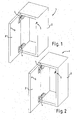
- Figure 1 and 2 shows each perspectively obliquely from the front a piece of furniture 1 with a furniture body 2 and an over it Hinged parts 4 pivotable door 3.
- the door 3 is shown in Figures 1 and 2 in their almost fully open position.
- the furniture 1 has an inventively equipped touch-latch assembly 5, which is shown in the extended or unlocked state and has explained in more detail below magnet units.
- the touch latch arrangement 5 according to FIG. 1 is accommodated in a cabinet side wall in a corresponding opening, whereas the touch latch arrangement 5 according to FIG. 2 is fastened to an inner wall of a furniture body side panel, e.g. glued on, screwed on or clipped on a mounting plate.
- a permanent magnet 6 or a magnet sleeve 6a in the door 3 is sunk to corresponding positions on an inner side of the furniture door 3.
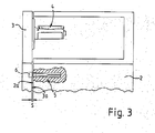
- Figure 3 shows the arrangement of Figure 1 schematically in perspective view obliquely from above, wherein a ceiling part of the furniture body 2 is not executed.
- the door 3 is shown in its closed position, whereby a closing gap S is formed between the inside 3a and a furniture body front 2a.
- the permanent magnet 6 with magnetic sleeve 6a which is indicated by dashed lines on the door 3, is in contact with parts of the touch-latch assembly 5, which is also highly schematic cut-free in the body 2 can be seen.
- Not shown in Figure 3 is a further lying below section of the furniture. 1
- Figure 4 shows an exploded view of the individual components of the touch-latch assembly 5 according to the invention with the magnetic means, wherein the permanent magnet 6 is accommodated in the magnet sleeve 6a, which has beipsiel mecanic circumferential ribs 6b, for clamping example in a corresponding hole in the door 3.
- the permanent magnet 6 is also clamped in the magnet sleeve 6a or may be glued or screwed therein.
- a substantially cylindrical metal sleeve 7 interacts with the permanent magnet 6 and has an external thread (not shown) on the outside thereof. Passing through the metal sleeve 7 in assembly, a plunger 8 is accommodated with a plunger head 9 and a plunger base 10 adjoining it via a shoulder.
- the plunger head 9 and the plunger base 10 each have approximately parallel opposite flat sections 9a and 10a or over opposite rounded sections 9b and 10b.
- an annular disc 11 is also frictionally inserted with a matched to the outer contour of the plunger base 10 inner contour, which provides with its inside a guide for the axially displaceable therein slide base 10.
- a guide sleeve 12 is provided with outwardly projecting thereon oppositely formed stop knobs 13, wherein the stop knobs 13 are positioned at the front end of the guide sleeve 12.
- a grid ring 14 is peripherally clipped to the guide sleeve 12.
- the raster ring 14 is designed as a partial ring, for example circumferentially by about 300 degrees of angle or interrupted by a gap, and freely rotatable about a guide groove or corresponding guide contours outside about the guide sleeve 12 movable.
- the guide sleeve 12 has an inner bore 12a with an internal thread into which the plunger base 10 can be screwed.
- the tappet foot 10 has a corresponding external thread on the outer sections 10b.
- the bolted together component with the plunger 8 and the guide sleeve 12 with grid ring 14 is longitudinally displaceable relative to other components of the touch-latch assembly 5 and accommodated in a plug-in part 16.
- a circumferentially protruding flange ring 16a is formed in a front portion of the male member 16.
- the flange ring 16a serves, in particular, to define a position of the insertion part 16 which is completely inserted in a bore and in which a back side of the flange ring 16a abuts in particular, for example, on the furniture body front side 2a.
- an internal thread 16b is formed, which is tuned to the external thread of the metal sleeve 7 and via which the metal sleeve 7 in the male member 16 on and is unscrewed.
- a guide portion 16c is connected to the rear over a small paragraph, in which opposite longitudinal slots 17a, 17b are present.
- a housing bottom 18 can be fitted on the shoulder of the front section of the insertion part 16.
- annular positioning edges 23a and 23b of a control cam or the control contour can function properly cooperate or for correct positioning between plug 16 and guide portion 16c and housing bottom 18 are formed on the guide portion 16c two opposite longitudinal ribs 19a and 19b, which in correspondingly configured longitudinal grooves 20a and 20b in the inner wall of the housing bottom 18 suitably come into contact.
- a suitably tuned coil spring 21 is housed in formed by the male part 16 and the housing bottom 18 in the assembled state cavity.
- the spiral spring 21 is clamped with assembled touch-latch assembly 5 inside between a base of the housing bottom 18 and an annular shoulder 12a at the rear end of the guide sleeve 12 at.
- FIG. 5 shows the arrangement with the assembled components according to FIG. 4 with the plunger 8 pushed out, whereby the metal sleeve 7 is not completely screwed in at the front area of the insertion part 16 and thus protrudes somewhat beyond the flange ring 16a to the front.
- a fixed counter stop for the plunger movement forward in the direction of displacement of the plunger 8 is the fixed position in the metal sleeve 7 accommodated annular disc 11, on which the guide sleeve 12 abuts with an end face 12a and 12a stop studs and thus the longitudinally displaceable movement of the plunger 8 after limited at the front.
- a plurality of longitudinally extending ribs 22 are provided on the outside of the plug-in part 16 or on the housing bottom 18.
- the external shape of the male part 16 or the housing bottom 18 can also be designed differently, e.g. polygonal, wherein the corresponding receiving recess in the furniture is matched accordingly match.
- the metal sleeve 7 consists in particular of a metallic or magnetizable or ferromagnetic material and interacts magnetically attractively with the permanent magnet 6.
- Figure 6a and 6b shows the arrangement of Figure 5 without furniture 1 as it results in the installed state with omission of parts of the housing bottom 18. From the housing bottom 18, only an inner provided guide portion 18a is shown with the annular grid edge 23a.
- the permanent magnet 6 is in its magnetic sleeve 6a in the closed position, wherein the front end of the plunger 8 abuts the permanent magnet 6.
- the plunger. 8 against the spring force of the relatively stronger pushed-out state of the plunger 8 compressed coil spring 21 in the plug 16 or in the housing bottom 18 retracted.
- the control contour comprises in particular the longitudinal slots 17a, 17b and the annular grid edges 23a and 23b, which also have latching depressions for the nubs 15, eg the detent recess 24.
- the two trapezoidal nubs 15 come in the state shown in Figure 6a, 6b respectively in a nose-shaped or jagged Detent recess 24 in the annular grid edge 23b.
- the locking knobs or knobs 15 are released from their latching and come here with their beveled bottom in abutment against the annular raster edge 23a, which has at this point a corresponding chamfer to the rear of a serrated depression contour and thus a rotation of the raster ring 14 so far enforces until the nubs 15 each at a stop position on the reach serrated bevel in the annular grid edge 23a and there are no longer movable in the direction of P1.
- the indenting force is released from the outside and thus pressed under the spring force of the coil spring 21 and the grid ring 14 in the direction P2 and the nubs 15 slide with their front bevel along a corresponding bevel on the annular edge raster 23b in the opposite longitudinal slots 17a, 17b opens and thus allows a forward displacement of the guide sleeve 12 with the stop knobs 13, wherein the grid ring 14 and the knobs 15 have been rotated so that they are in line with the stop knobs 13 and also in the longitudinal slots forward in Direction P2 are moved.
- the plunger 8 advances according to arrow P2 in Figure 7a, 7b, thereby pushing the permanent magnet 6 and thus the door 3 from the furniture body 2 forward.
- the metal sleeve 7 comes from the vicinity or the magnetic effective range of the permanent magnet 6, so that the door 3 after the permanent magnet 6 comes out of contact with the extended plunger by itself still slightly pivots (see Figure 7a, 7b).
- the stop nubs 13 and the trapezoidal nubs 15 slide back along the longitudinal slots 17a, 17b until the nubs 15 come to rest on the rear annular grid edge 23a and are guided on a slope backwards until they over a stop edge by turning the grid ring Enter 14 in a stop position and from there with the release of the pushing force or simultaneous pressing of the coil spring 21 forward in the position shown in Figure 6a, 6b occur.
- the touch-latch assembly is again in its locked or closed position.
- FIGS. 7b to 11b show the corresponding positions with respective sectional arrangement.
- FIGS. 8a, 8b show the arrangement according to FIGS. 6a and 6b with housing bottom 18 shown completely.
- FIGS. 9a to 11b show a corresponding arrangement with metal sleeve 7 completely screwed into the front section of the insertion part 16.
- the closing gap S corresponds to the projection of the plunger 8 via the metal sleeve 7 and the thickness of the flange ring 16a.
- the closing gap S according to FIG. 6b additionally comprises the projection of the metal sleeve 7 relative to the insertion part 16.
- the arrangement according to the invention always maintains a constant distance S '(see FIG. 8b) between the permanent magnet 6 or the stop surface 9c and a magnetic middle surface 7a in the closed state of the door 3. see Figure 4) of the metal sleeve 7 realized, which in particular no variability of Magnetanziehkraft or triggering or Wegdschreibkraft to release the closed state or at the beginning of Ausschubbwegung the plunger 8 is connected.
Landscapes
- Engineering & Computer Science (AREA)
- Mechanical Engineering (AREA)
- Physics & Mathematics (AREA)
- Electromagnetism (AREA)
- Closing And Opening Devices For Wings, And Checks For Wings (AREA)
- Apparatus For Radiation Diagnosis (AREA)
- Wing Frames And Configurations (AREA)
Abstract
Description
- Die Erfindung betrifft eine Vorrichtung gemäß dem Oberbegriff der Ansprüche 1 und 2 und ein Möbel gemäß Anspruch 16.
- Möbel mit zueinander bewegbaren Möbelteilen beispielsweise Schrankkorpusse mit über Beschläge verschwenkbaren Türen oder Klappen bzw. mit Möbelkorpusse, an welchen eine Schublade bzw. ein Auszug oder dergleichen mittels einer Führung bewegbar untergebracht ist, sind in unterschiedlichen Ausgestaltungen bekannt.
- Bei derartigen Möbeln können so genannte Touch-Latch Anordnungen für Schubladen, Türen oder Klappen Verwendung finden, welche über Zuhaltemechanismen das bewegbare Möbelteil unter Ausbildung eines Schließspalts zwischen Korpus und bewegbaren Möbelteil in einer Schließstellung des bewegbaren Möbelteils halten. Beispielsweise können dafür mechanische Verriegelungen oder Magnetmittel eingesetzt werden, um das bewegbare Möbelteil z.B. magnetisch gegenüber dem Möbelkorpus in einer Schließstellung zu halten. Insbesondere bei Möbeln mit mehreren bewegbaren Möbelteilen ist es erwünscht, nach dem Zusammenbau des Möbels einen für jedes bewegbare Möbelteil individuellen Schließspalt zum Korpus einzustellen, um zum Beispiel durch die Montage bedingte Abweichungen von einer gewünschten idealen Montageposition der Beschläge oder Führungen auszugleichen. Beispielsweise lassen sich auf diese Weise benachbarte bewegbare Möbelteil genau ausrichten, was aus optischen Gründen für den Endnutzer von großer Bedeutung ist. Gerade bei Möbeln in Touch-Latch Ausführung, die insbesondere für grifflose Möbelteile bevorzugt sind, ist die exakte fluchtende Anordnung der Frontpartien der bewegbaren Möbelteile erwünscht.
- Aufgabe der Erfindung ist es, eine Vorrichtung bereit zu stellen bzw. ein Möbel mit einer solchen Vorrichtung, mit welcher es bei Möbeln in Touch-Latch Ausführung einfach möglich ist, eine Feinjustage zu ermöglichen, insbesondere Montagefehler von Beschlägen bzw. Führungen auszugleichen bzw. Voraussetzungen zu schaffen, um ein Möbelteil in einen unter ästhetischen und technischen Gesichtspunkten vorteilhaften Endmontagezustand zu bringen bzw. den Bedienkomfort des Möbels zu erhöhen.
- Diese Aufgabe wird durch die Ansprüche 1 bis 3 und 16 gelöst. In den abhängigen Ansprüchen sind vorteilhafte Ausgestaltungen des Erfindungsgegenstandes aufgezeigt.
- Die Erfindung geht zunächst aus von einer Vorrichtung zum Öffnen und/oder Schließen eines Möbels, wobei das Möbel ein gegenüber einem feststehenden Möbelkorpus bewegbaren Möbelteil umfasst, wobei die Vorrichtung über Magnetmittel verfügt, mit welchen im eingebauten Zustand der Vorrichtung am Möbel, im Schließzustand des bewegbaren Möbelteils die beiden Möbelteile unter Ausbildung eines Schließspalts zwischen Möbelkorpus und bewegbarem Möbelteil zueinander in Position gehalten werden sowie mit Ausstoßmitteln, die aus einer eingerückten Verriegelposition in einem Schließzustand des Möbels durch Drücken auf das bewegbare Möbelteil entgegen einer Öffnungsrichtung des Möbelteils lösbar und unter Vorspannung ausschiebbar sind, so dass das bewegbare Möbelteil mit den Ausstoßmitteln weggedrückt wird, insbesondere mit so genannten Touch-Latch Anordnungen, und die Magnetmittel eine erste Einheit mit einem Magnetteil und eine zweite Einheit mit einem metallischen Gegenstück umfassen, wobei eine Einheit am bewegbaren Möbelteil und die andere Einheit am Möbelkorpus anordenbar ist. Ein wesentlicher Aspekt der Erfindung liegt darin, dass Magnetmittel derart ausgebildet sind, dass im Schließzustand des bewegbaren Möbelteils das Magnetteil nicht in Kontakt mit dem metallischen Gegenstück ist, wenn das bewegbare Möbelteil mit einer Magnethaltekraft in dem Schließzustand gehalten wird. Mit einer erfindungsgemäßen Anordnung ist es besonders zuverlässig und einfach möglich, einen gewünschten Schließzustand zwischen dem bewegbaren Möbelteil und dem Möbelkorpus festzulegen, da die Magnethaltekraft über einen nicht unterschreitbaren Abstand zwischen den Magnetmitteln definiert ist. Insbesondere ist es von Vorteil, dass kein direkter Kontakt zwischen dem Magnetteil und metallischen Gegenstück vorhanden ist bzw. eine gewünschte wirksame Zuhaltekraft zwischen Möbelkorpus und bewegbarem Möbelteil entsprechend durch den Abstand der Magnetmittel definiert ist. Der Abstand ist insbesondere nicht "null" und aus technischen Überlegungen heraus so zu wählen, dass er innerhalb eines Nahbereichs liegt, in welchem vergleichsweise ein noch hoher Magnet-Wirkungsgrad erzielbar ist, z.B. im Bereich von über 50 % insbesondere über 80 % einer maximalen Magnethaltekraft bei direktem Kontakt von Magnetteil und metallischem Gegenstück.
- Mit der vorgeschlagenen Anordnung sind insbesondere keine relativ hohen Abreiß- bzw. Abstoßkräfte zum Trennen der Magnetmittel notwendig, was ansonsten bei direkt in Kontakt befindlichen Magnetmittelflächen der Fall ist. Daher muss auch keine entsprechend größer dimensionierte Vorspannung zum Beispiel eine Feder zur Bereitstellung der Vorspannung verwendet werden bzw. muss diese nicht überdimensioniert werden. Erfindungsgemäß ist dadurch z.B. eine geringer dimensionierte Feder einsetzbar, welche demgemäß auch relativ kleinere Kräfte zum Zusammendrücken bzw. Spannen der Touch-Latch Anordnung benötigt, was das Schließen des Möbels für eine Person angenehmer bzw. einfacher gestaltet.
- Insbesondere können vorteilhafterweise bei mehreren mit jeweils einer vorgeschlagenen Vorrichtung ausgestatteten bewegbaren Möbelteilen in einem Möbelkorpus bzw. von benachbarten Korpussen alle mit derselben Magnet-Zuhaltekraft im Schließzustand versehen werden, auch wenn unterschiedliche Schließspaltbreiten bei den einzelnen bewegbaren Möbelteilen für die exakte Fluchtung der Frontpartien notwendig wird. Zum Beispiel kann bei der Erstmontage eine individuell unterschiedliche starke Nachjustierung der Frontpartien und damit der Schließspaltbreiten aufgrund von z.B. Montagefehlern nötig sein. Dies ist für eine komfortable Bedienung der bewegbaren Möbelteile besonders vorteilhaft. Denn die Magnet-Zuhaltekrafte bzw. Kraftverhältnisse der Magnetverriegelungsmittel, welche beim Öffnen wirken, können damit einheitlich gestaltet werden. Einen Benutzer kann damit jedes bewegbare Möbelteil mit der gleichen aufzubringenden Auslösekraft öffnen, was als angenehm empfunden wird, bzw. umgekehrt werden alle bewegbaren Möbelteile mit der gleichen Zuhaltekraft in der Schließstellung gegenüber dem Möbelkorpus gehalten.
- Demgegenüber wäre bei einem direkten Kontakt zwischen Magnetteil und metallischem bzw. ferromagnetischem Gegenstück die Zuhaltekraft nicht definiert vorgebbar bzw. keine Funktion eines Bauteilmaßes bzw. einer Einstellgröße.
- Vielmehr hängt in diesem Fall die Zuhaltekraft im Wesentlichen von inneren bzw. physikalischen Größen bzw. den Magneteinheiten selbst ab, z.B. von einer zeitlichen Abschwächung der Magnetkraft eines Permanentmagneten im Magnetteil. Erfindungsgemäß ist es sogar denkbar, eine gewünschte Zuhaltekraft, welche zum Lösen des Schließzustand beispielsweise von einer Person am bewegbaren Möbelteil zum Öffnen entgegen der wirkenden Magnetkräfte aufzubringen ist, dauerhaft einem Zielwert anzupassen, wenn der Abstand zwischen Magnetteil und metallischem Gegenstück zwar festgelegt ist aber auf unterschiedliche feste Werte nachstellbar ist, um z.B. den betreffenden Abstand im Schließzustand ggf. von Zeit zu Zeit geringfügig zu verringern und damit insbesondere eine Magnetkraftabschwächung auszugleichen.
- Unter dem Magnetteil kann insbesondere jedes magnetisch wirkende Teil verstanden werden, insbesondere ein Magnet bzw. Permanentmagnet mit oder ohne daran angeordnetem metallischen bzw. ferromagnetischem Teil. Das metallische Gegenstück kann ebenfalls ein beliebiges magnetisch wirkendes einteiliges oder mehrteiliges Teil sein, insbesondere ein ferromagnetisches bzw. magnetisches Teil oder auch ein Magnet bzw. Permanentmagnet, wobei im Einbauzustand der Vorrichtung die magnetische Polungen so ausgerichtet sind, dass Magnetteil und metallisches Gegenstück aufeinander anziehend wirken und damit im Magnetwirkungsbereich das bewegbare Möbelteil an den Korpus herangezogen wird.
- Die Erfindung geht außerdem von einer Vorrichtung, insbesondere einem Möbelbeschlag aus, mit einem Magnetteil oder einem ferromagnetischen Teil und einem in einem Gehäuse angeordneten Ausstoßelement, wobei das Ausstoßelement eine Anschlagfläche aufweist, und wobei das Magnetteil oder ferromagnetische Teil eine von der Anschlagfläche beabstandet angeordnete Magnetfläche aufweist. Der wesentliche Aspekt der Erfindung liegt in diesem Fall darin, dass mit dem Ausstoßelement und dem Magnetteil oder ferromagnetischen Teil ein Stellmechanismus gekoppelt ist, so dass mittels des Stellmechanismus das Ausstoßelement und der Magnetteil oder ferromagnetische Teil gleichzeitig derart verstellbar sind, dass der Abstand zwischen der Anschlagfläche und Magnetfläche in den verschiedenen Einstellpositionen im Wesentlichen gleich ist. Der Abstand zwischen der Anschlag- und Magnetfläche bezieht sich insbesondere darauf, wenn Anschlag- und Magnetfläche sich definiert zueinander angenähert und über das Ausstoßelement beabstandet in einer Anziehposition bzw. in einem zwischen den betreffenden Teilen existierenden Magnetkraftwirkbereich befinden. Mit dem Stellmechanismus ist es insbesondere möglich eine Einstellung im Hinblick auf einen gewünschten Abstand zwischen Teilen der Vorrichtung vorzunehmen, ohne dabei die wirkende Magnetanziehkraft zwischen der Anschlag- und der Magnetfläche in der Anziehposition verändern zu müssen.
- Ausgehend von der eingangs genannten Vorrichtung für Möbel bzw. z.B. Touch-Latch Anordnung mit Magnetmitteln liegt ein weiterer wesentlicher Aspekt der Erfindung darin, dass die Ausstoßmittel ein zu den Magnetmitteln benachbart angeordnetes, insbesondere ein durch die Magnetmittel durchgreifendes nicht magnetisches Ausstoßelement umfassen, das derart ausgebildet ist, dass im Einbauzustand der Vorrichtung durch Einwirken auf das Ausstoßelement der Schließspalt verstellbar ist. Insbesondere kann das Einwirken auf das Ausstoßelement bei dem nicht im Schließzustand befindlichen bewegbaren Möbelteil erfolgen, weil das Ausstoßelement gut zugänglich ist bzw. im ausgeschobenen Zustand sich befindet, ohne dass dabei das bewegbare Möbelteil aus räumlichen Gründen stört. Bevorzugt durchgreifen bzw. durchstoßen die Ausstoßmittel die Magnetmittel, es ist jedoch auch eine andere benachbarte Anordnung der Ausstoßmittel und Magnetmittel denkbar. Durch diese Vorgehensweise kann auf einfache Weise und insbesondere ohne zusätzliche Verstellmittel der Schließspalt für jedes bewegbare Möbelteil individuell angepasst werden.
- Vorteilhafterweise sind die beiden Einheiten der Magnetmittel im Schließzustand des bewegbaren Möbelteils durch einen materialfreien Bereich voneinander beabstandet, insbesondere durch einen Luftspalt getrennt. Auf diese Weise lässt sich die gesamte Anordnung unkompliziert bzw. mit wenigen Bauteilen bzw. materialsparend realisieren.
- Bevorzugt sind die beiden Einheiten der Magnetmittel im Schließzustand des bewegbaren Möbelteil über das Ausstoßelement voneinander beabstandet. Das Ausstoßelement, welches beispielsweise insbesondere aus Kunststoff oder einem anderem nicht magnetisierbaren bzw. Nicht-Ferromagnetmaterial besteht, kann damit neben der Bereitstellung eines Ausstoß- bzw. Einschubmechanismus als Abstandhalter wirken. Der Überstand des Ausstoßelements im Schließzustand am betreffenden Magnetmittel beeinflusst außerdem die Breite des Schließspalts. Der Schließspalt zwischen Korpus und bewegbarem Möbelteil im Schließzustand kann z.B. im Wesentlichen dem Überstand des Ausstoßelements entsprechen oder größer sein bzw. einen zusätzlichen Anteil aufweisen. Im Einzelfall kann bei z.B. im Korpus oder Möbelteil teilweise versenktem Magnetmittel der Schließspalt auch kleiner sein als der Überstand des Ausstoßelements am entsprechenden Magnetmittel.
- Weiter wird vorgeschlagen, dass das Ausstoßelement so verdrehbar um seine Längsachse ausgestaltet ist, dass im Einbauzustand der Vorrichtung durch Verdrehen des Aufstoßelements um seine Längsachse der Schließspalt verstellbar ist. Durch Verdrehen des Ausstoßelements lässt sich besonders schnell und exakt ein Schließspalt einstellen. Vorteilhafterweise wird dabei der Überstand des Ausstoßelements zum benachbart angeordneten Magnetmittel bzw. dem vom Ausstoßelement durchgriffenen Magnetmittel nicht verändert. Beispielsweise können über entsprechende Gewindeabschnitte sehr präzise und auf engsten Raum die Vorraussetzungen geschaffen werden, um mittels des Ausstoßelements den Schließspalt beispielsweise bis auf einen Bruchteil eines Millimeters genau vorzugeben. Über die Tiefe bzw. Länge der Gewindeausbildung kann zudem ein maximaler Verstellweg für das verdrehbare Ausstoßelement bzw. die Schließspalteinstellung vorgegeben werden. In der Regel beträgt ein solcher Verstellbereich beispielsweise mehrere Millimeter. Insbesondere 3 mm bis über 6 mm. Der Schließspalt kann z.B. 1 mm bis über 3 mm, insbesondere ca. 1,5 Millimeter betragen.
- Besonders vorteilhaft ist es, wenn das Ausstoßelement durch Verdrehen um seine Längsachse gemeinsam mit am Ausstoßelement drehfest angebrachtem Magnetmittel gegenüber einer Aufnahme in Richtung der Längsachse des Ausstoßelements bewegbar ist. Damit kann ein vorgegebener Abstand im Schließzustand zwischen dem Magnetteil und dem metallischen Gegenstück trotz Verstellung eines Schließspaltes konstant beibehalten werden. Denn durch das gemeinsame Verdrehen bleibt ein Überstand des Ausstoßelements gegenüber den entsprechenden Magnetmitteln erhalten. Der Schließspalt setzt sich z.B. aus einem Überstand des Ausstoßelements gegenüber den daran drehfest angebrachten Magnetmitteln und einem durch Verdrehen variabel einstellbaren Anteil zusammen, welcher durch die jeweilige Position der betreffenden Magnetmittel, z.B. dem metallischen Gegenstück bestimmt ist. Wird beispielsweise durch Verdrehen am Ausstoßelement die darin drehfest angebrachten Magnetmittel nach außen bewegt, so dass diese z.B. einen Millimeter an der Frontseite des Korpus über, und steht in der Schließstellung das Ausstoßelement 1,5 Millimeter an den Magnetmitteln über, wird der dann sich ergebende Schließspalt aus diesen zwei Anteilen auf gesamt 2,5 Millimeter gebildet, also einem an sich konstanten Überstand des Ausstoßelements und einem Abstand einer Bezugskante der Magnetmittel zur Front des betreffenden Möbelteils bzw. des Möbelkorpus.
- Bevorzugt ist die Aufnahme als Einsteckteil ausgestaltet, welches am Möbelkorpus oder bewegbaren Möbelteilen einsetzbar ist. Die Aufnahme, in welche das Ausstoßelement mit den Magnetmitteln bewegbar ist, ist insbesondere als Einsteckhülse oder dergleichen ausgestaltet und kann auf einfache Weise eingebracht bzw. ausgetauscht werden. Dafür ist lediglich eine Vertiefung zur Aufnahme des Einsteckteils vorzusehen. Insbesondere ist das Einsteckteil außenzylindrisch und kann in eine zylindrische Bohrung im Möbelkorpus oder bewegbaren Möbelteil eingesteckt werden. Dies vereinfacht die Herstellung und Montage der Vorrichtung.
- Weiter wird vorgeschlagen, dass das Ausstoßelement so ausgebildet ist, dass im Einbauzustand der Vorrichtung die Einstellung des Schließspalts werkzeuglos möglich ist. Somit kann jederzeit ein gewünschter Schließspalt beispielsweise von Hand durch eine Person eingestellt werden. Dies ist insbesondere für eine nachträgliche Feinjustage am zusammengebauten Möbel vorteilhaft. Insbesondere sind nur vergleichsweise geringe Verstellkräfte zum Verdrehen des Ausstoßelements notwendig, die von Hand bzw. ohne Hilfsmittel problemlos aufgebracht werden können.
- In einer bevorzugten Ausführungsform des Erfindungsgegenstandes sind Führungsmittel vorhanden, mit denen die Ausstoßmittel zum Lösen aus der Verriegelungsposition um einen mindestens notwendigen Eindrückweg bewegbar sind, der zu einem anschließend entgegengesetzt zurücklegbaren maximalen Ausstoßweg der Ausstoßmittel vergleichsweise gering ist. Damit kann ein besonders bedienfreundliches Öffnen bzw. Ausstoßen des bewegbaren Möbelteils realisiert werden. Insbesondere kann durch ein vergleichsweise kurzes bzw. geringfügiges Eindrücken am bewegbaren Möbelteil die Touch-Latch Verriegelung gelöst werden und das bewegbare Möbelteil bewegt sich selbsttätig so weit, dass danach ggf. auch auf weiter hinten liegende Bereiche des geöffneten bewegbaren Möbelteils unmittelbar zugegriffen werden kann.
- Weiter ist es vorteilhaft, dass die Führungsmittel derart ausgebildet sind, dass der maximale Ausstoßweg über ca. fünf mal größer insbesondere über ca. 10 bis 20 mal größer als der mindestens notwendige Eindrückweg ist. Mit diesen Relationen lässt sich ein bewegbares Möbelteil durch eine Person schnell und bequem aus der Schließ- bzw. Verriegelungsposition lösen und anschließend automatisiert bzw. selbsttätig um einen gewünschten Ausschiebeweg oder Ausschwenkwinkel aus der Schließposition wegdrücken. Damit wird insbesondere der Bedienkomfort für das mit der vorgeschlagenen Vorrichtung ausgestattete Möbel weiter erhöht.
- In einer bevorzugten Ausgestaltung des Erfindungsgegenstandes umfassen die Führungsmittel zumindest ein Anschlagelement, welches mit der axialen Bewegung des Ausstoßelements gekoppelt ist und zur Begrenzung der Ausstoßbewegung an einem Gegenanschlag anstößt. Damit kann die Ausstoßbewegung, bei welcher eine nicht unerhebliche Aufprallenergie erzeugt wird, gezielt und ohne nachteilige Abnutzung oder Beschädigung an Bauteilen abgefangen bzw. ggf. abgefedert werden. Zum Beispiel können Anschlagflächen am Anschlagelement und/oder am Gegenanschlag entsprechend gepuffert oder abgedämpft sein. Insbesondere können mehrere und insbesondere zwei zur Längsverschiebeachse gegenüberliegende Anschlagnoppen vorgesehen werden. Die Anschlagnoppen können z.B. am Ausstoßelement bzw. an einem mit diesem verbundenen Bauteil überstehend ausgeformt sein und jeweils in einer Führungsnut zur Führung des Ausstoßelements bei der Hin- und Herbewegung des Ausstoßelement entlang gleiten. Die Führungsnuten können insbesondere in einem Gehäuse für die Touch-Latch Anordnung bzw. für das Ausstoßelement ausgebildet sein, innerhalb dessen bewegliche Teile der Touch-Latch Anordnung untergebracht sind.
- Weiter ist es vorteilhaft, wenn die Führungsmittel zusätzlich zu dem Anschlagelement zumindest ein Rastelement umfassen, welches mit der Bewegung des Ausstoßelements gekoppelt und beweglich gegenüber dem zumindest einen Anschlagelement ist und mit einer Steuerkontur so zusammenwirkt, dass das Ausstoßelement in der Verriegelposition verrastbar und wieder entrastbar ist. Damit kann eine Trennung in der Funktion der Bewegungssteuerung erfolgen, wobei die wie oben erläuterte Anschlagfunktion von der Rast- bzw. Bewegungssteuerung durch die Rastelemente getrennt werden. Damit können gegenüber bisherigen Touch-Latch Anordnungen, bei welchen regelmäßig Abnutzungserscheinungen durch insbesondere das Anschlagen von zum Beispiel Rastnasen am Ende einer Ausstoßbewegung auftreten, vermieden werden. Denn mit der vorgeschlagenen Anordnung treten keine Anschlagbelastungen an dem Rastelement auf, da der Anschlag bzw. Aufprall am Ende des Ausstoßens über die Anschlagelemente erfolgt, wobei ggf. an den Anschlagelementen auftretende Abnutzungen unproblematisch für deren Anschlagfunktion ist bzw. diese keine Steuerungsaufgaben übernehmen. Erfindungsgemäß kann damit eine exakte Steuerung der Bewegung des Ausstoßelements bzw. können relativ geringe Eindrückwege am Ausstoßelement realisiert werden, da insbesondere Schaltradien bzw. Rast- oder Steuerkanten an den Rastelementen sich nicht mit der Zeit abnützen bzw. abrunden und daher eine dauerhaft exakte Steuerung möglich ist.
- Bevorzugt umfasst das Rastelement zwei gemeinsam um die Längsachse des Ausstoßelements drehbar angeordnete Rastnoppen.
- Es ist überdies vorteilhaft, wenn das Rastelement und die Steuerkontur so aufeinander abgestimmt sind, dass bei deren Zusammenspiel im Betrieb der Vorrichtung nahezu keine Abnutzung an dem Rastelement und/oder der Steuerkontur stattfindet, insbesondere tangential zur Längsachse des Ausstoßelements an den Rastnoppen wirkende Kräfte nahezu keine Abnutzung hervorrufen. Mit dieser Maßnahme kann die dauerhafte und exakte Steuerung der Bewegung des Ausstoßelements weiter verbessert werden.
- Die Erfindung betrifft außerdem ein Möbel mit einem gegenüber mit einem feststehenden Möbelkorpus bewegbaren Möbelteil, insbesondere mit einer Türe, Klappe oder Schublade, welche mit einer der vorgenannten Vorrichtungen versehen ist. Damit lassen sich die bereits oben genannten Vorteile für ein entsprechendes Möbel verwirklichen.
- In den Zeichnungsfiguren wird die Erfindung unter Angabe weiterer Merkmale und Vorteile näher erläutert. Im einzelnen zeigt:
- Figur 1
- ein Möbel in perspektivischer Ansicht schräg von oben mit einer erfindungsgemäßen Vorrichtung,
- Figur 2
- ein Möbel mit einer alternativen Ausgestaltung der erfindungsgemäßen Vorrichtung,
- Figur 3
- eine perspektivische Ansicht auf den oberen Teil des Möbels aus Figur 1, teilweise freigeschnitten und unter Weglassung einer das Möbel nach oben abschließenden Deckplatte in Schließstellung einer Möbeltüre,
- Figur 4
- eine Explosionsdarstellung der erfindungsgemäßen Vorrichtung aus Figur 1,
- Figur 5
- die Vorrichtung gemäß Figur 4 im zusammengebauten Zustand in perspektivischer Ansicht von der Seite,
- Figur 6a und 6b
- die Vorrichtung gemäß Figur 5 unter Weglassung eines Bauteilabschnittes in einer Anordnung, die sich in einem Schließzustand im eingebauten Zustand der Vorrichtung einstellt,
- Figur 7a und 7b
- die Anordnung gemäß Figur 5 in Draufsicht und in geschnittener Draufsicht,
- Figur 8a und 8b
- die Ansichten gemäß Figur 7a und 7b in einem Schließzustand,
- Figur 9a und 9b
- die Vorrichtung gemäß Figur 8a und 8b unter Ausbildung eines verringerten Schließspalts,
- Figur 10a und 10b
- die Ansichten gemäß Figur 9a und 9b in einer geöffneten Position und
- Figur 11a und 11b
- die Ansichten gemäß Figur 10a und 10b um 90° gedreht.
- Figur 1 und 2 zeigt jeweils perspektivisch schräg von vorne ein Möbel 1 mit einem Möbelkorpus 2 und einer daran über Scharnierteile 4 verschwenkbaren Türe 3. Die Türe 3 ist in den Figuren 1 und 2 in ihrer nahezu vollständig geöffneten Position dargestellt.
- Das Möbel 1 weist eine erfindungsgemäß ausgestattete Touch-Latch Anordnung 5 auf, welche im ausgefahrenen bzw. entriegelten Zustand gezeigt ist und über noch weiter unten näher erläuterte Magneteinheiten verfügt. Die Touch-Latch Anordnung 5 gemäß Figur 1 ist in einer Korpusseitenwand in einer entsprechenden Öffnung untergebracht, wohingegen die Touch-Latch Anordnung 5 gemäß Figur 2 an einer Innenwandung eines Möbelkorpus-Seitenteils befestigt ist, z.B. angeklebt, angeschraubt bzw. auf einer Montageplatte aufgeklipst. Entsprechend der Positionierung der Touch-Latch Anordnungen 5 ist an jeweils entsprechenden Positionen an einer Innenseite der Möbeltür 3 ein Permanentmagnet 6 bzw. eine Magnethülse 6a in der Tür 3 versenkt.
- Figur 3 zeigt die Anordnung gemäß Figur 1 schematisiert in perspektivischer Ansicht schräg von oben, wobei ein Deckenteil des Möbelkorpus 2 nicht ausgeführt ist. Die Tür 3 ist in ihrer geschlossenen Position dargestellt, wodurch zwischen deren Innenseite 3a und einer Möbelkorpus-Frontseite 2a ein Schließspalt S ausgebildet wird. Der Permanentmagnet 6 mit Magnethülse 6a, welcher gestrichelt an der Tür 3 angedeutet ist, ist in Anlage mit Teilen der Touch-Latch Anordnung 5, welche ebenfalls stark schematisiert freigeschnitten im Korpus 2 ersichtlich ist. Nicht dargestellt in Figur 3 ist ein weiter unten liegender Abschnitt des Möbels 1.
- Figur 4 zeigt in Explosionsdarstellung die einzelnen Bauteile der erfindungsgemäßen Touch-Latch Anordnung 5 mit den Magnetmitteln, wobei der Permanentmagnet 6 in der Magnethülse 6a unterbringbar ist, welche beipsielsweise umlaufende Rippen 6b aufweist, zur Festklemmung beispielsweise in einer entsprechenden Bohrung in der Tür 3. Der Permanentmagnet 6 wird ebenfalls in der Magnethülse 6a eingeklemmt bzw. kann darin festgeklebt oder eingeschraubt sein. Mit dem Permanentmagnet 6 wirkt magnetisch eine im Wesentlichen zylindrische Metallhülse 7 zusammen, die ein nicht dargestelltes Außengewinde an deren Außenseite besitzt. Durch die Metallhülse 7 im Zusammenbau durchgreifend ist ein Stößel 8 mit einem Stößelkopf 9 und einem dazu über einem Absatz sich anschließenden Stößelfuß 10 untergebracht. Der Stößelkopf 9 und der Stößelfuß 10 verfügen jeweils über in etwa parallele gegenüberliegende Flachabschnitte 9a bzw. 10a bzw. über gegenüberliegende abgerundete Abschnitte 9b bzw. 10b. In der Metallhülse 7 ist außerdem eine Ringscheibe 11 mit einer auf die Außenkontur des Stößelfußes 10 abgestimmten Innenkontur reibschlüssig eingeschoben, die mit ihrer Innenseite eine Führung für den axial darin verschieblichen Stößelfuß 10 bereitstellt. Nach hinten anschließend an die Metallhülse 7 ist eine Führungshülse 12 mit außen überstehend daran gegenüberliegend ausgeformten Anschlagnoppen 13 vorgesehen, wobei die Anschlagnoppen 13 am vorderen Ende der Führungshülse 12 positioniert sind. In einem mittleren und über Absätze etwas vertieften Abschnitt der Führungshülse 12 ist ein Rasterring 14 außenumfänglich an der Führungshülse 12 aufgeklipst. Der Rastering 14 ist als Teilring, beispielsweise umfänglich um ca. 300 Winkelgrad ausgebildet bzw. über einen Spalt unterbrochen, und über eine umfängliche Führungsnut bzw. entsprechende Führungskonturen frei drehbar außen um die Führungshülse 12 beweglich. Am Rasterring 14 sind gegenüberliegend ausgeformte trapezförmige Noppen 15 mit relativ scharfen Kanten vorhanden. Die Führungshülse 12 weist eine Innenbohrung 12a mit einem Innengewinde auf, in welches der Stößelfuß 10 einschraubbar ist. Hierzu verfügt der Stößelfuß 10 über ein entsprechendes Außengewinde an den Außenabschnitten 10b.
- Das zusammengeschraubte Bauteil mit dem Stößel 8 und der Führungshülse 12 mit Rasterring 14 ist gegenüber anderen Bauteilen der Touch-Latch Anordnung 5 längs verschieblich und in einem Einsteckteil 16 untergebracht. In einem vorderen Abschnitt des Einsteckteils 16 ist ein umfänglich abstehender Flanschring 16a ausgebildet. Der Flanschring 16a dient insbesondere dazu, eine vollständig in einer Bohrung eingesteckte Position des Einsteckteils 16 zu definieren, in dem eine Rückseite des Flanschrings 16a insbesondere beispielsweise an der Möbelkorpus-Frontseite 2a anliegt. Im vorderen Teil des Einsteckteils 16 an dessen Innenwandung ist ein Innengewinde 16b ausgebildet, welches auf das Außengewinde der Metallhülse 7 abgestimmt ist und über welches die Metallhülse 7 im Einsteckteil 16 ein- und ausschraubbar ist. An den vorderen Abschnitt des Einsteckteils 16 schließt sich nach hinten über einen geringen Absatz ein Führungsabschnitt 16c an, in welchem gegenüberliegende Längsschlitze 17a, 17b vorhanden sind. Über den Führungsabschnitt 16c außen übergeschoben ist ein Gehäuseboden 18 am Absatz des vorderen Abschnitt des Einsteckteils 16 anliegend aufsteckbar.
- Damit Ringrasterkanten 23a und 23b einer Steuerkurve bzw. der Steuerkontur funktionsrichtig zusammenwirken können bzw. zur richtigen Positionierung zwischen Einsteckteil 16 bzw. Führungsabschnitt 16c und Gehäuseboden 18 sind am Führungsabschnitt 16c zwei gegenüberliegende Längsrippen 19a und 19b ausgebildet, welche in entsprechend ausgestaltete Längsnuten 20a und 20b in der Innenwandung des Gehäusebodens 18 passend in Anlage kommen. Im vom Einsteckteil 16 bzw. vom Gehäusebodens 18 im zusammengesteckten Zustand ausgebildeten Hohlraum ist eine entsprechend abgestimmte Spiralfeder 21 untergebracht. Die Spiralfeder 21 liegt bei zusammengebauter Touch-Latch Anordnung 5 eingespannt innen zwischen einer Grundfläche des Gehäusebodens 18 und einem Ringabsatz 12a am hinteren Ende der Führungshülse 12 an.
- Figur 5 zeigt die Anordnung mit den zusammengebauten Bauteilen gemäß Figur 4 mit ausgeschobenem Stößel 8, wobei die Metallhülse 7 nicht vollständig im vorderen Bereich des Einsteckteils 16 eingeschraubt ist und somit etwas über den Flanschring 16a nach vorne übersteht. Als feststehender Gegenanschlag für die Stößelbewegung nach vorne in Verschieberichtung des Stößels 8 dient die positionsfest in der Metallhülse 7 untergebrachte Ringscheibe 11, an der die Führungshülse 12 mit einer stirnseitigen Ringfläche 12a bzw. mit den Anschlagnoppen 13 anschlägt und damit die längsverschiebliche Bewegung des Stößel 8 nach vorne begrenzt.
- Damit das Einsteckteil 16 mit dem daran angeordneten Gehäuseboden 18 fest bzw. sicher in einer entsprechenden Aufnahmebohrung im Korpus 2 hält, sind außen am Einsteckteil 16 bzw. am Gehäuseboden 18 mehrere längsverlaufende Rippen 22 vorgesehen. Die Außenform des Einsteckteil 16 bzw. des Gehäusebodens 18 kann auch anders gestaltet sein, z.B. mehrkantig, wobei die entsprechende Aufnahmevertiefung im Möbel darauf entsprechend passend abgestimmt ist.
- Die Metallhülse 7 besteht insbesondere aus einem metallischen bzw. magnetisierbaren oder ferromagnetischen Werkstoff und wirkt mit dem Permanentmagnet 6 magnetisch anziehend zusammen.
- Figur 6a und 6b zeigt die Anordnung gemäß Figur 5 ohne Möbel 1 wie sie sich im eingebauten Zustand unter weglassung von Teilen des Gehäusebodens 18 ergibt. Vom Gehäuseboden 18 ist lediglich ein innen vorgesehener Führungsabschnitt 18a mit der Ringrasterkante 23a gezeigt. Bei der Anordnung gemäß Figur 6a und 6b befindet sich der Permanentmagnet 6 in seiner Magnethülse 6a in Schließposition, wobei das vordere Ende des Stößels 8 am Permanentmagnet 6 anliegt. Dabei ist der Stößel. 8 gegen die Federkraft der relativ zum ausgeschobenen Zustand des Stößels 8 stärker zusammengedrückten Spiralfeder 21 im Einsteckteil 16 bzw. im Gehäuseboden 18 eingefahren. Unter Wirkung der Spiralfeder 21 wird die Führungshülse 12 mit den Noppen 15 nach vorne gegen die Ringrasterkante 23b am Führungsabschnitt 16c angedrückt. Die Steuerkontur umfasst insbesondere die Längsschlitze 17a, 17b und die Ringrasterkanten 23a und 23b, welche auch Einrastvertiefungen für die Noppen 15 aufweisen, z.B. die Rastvertiefung 24. Die beiden trapezförmigen Noppen 15 kommen im Zustand gemäß Figur 6a, 6b jeweils in eine nasenförmige bzw. zackenförmige Rastvertiefung 24 in der Ringrasterkante 23b. Unter Krafteinwirkung der Spiralfeder 21 ist damit auch der Stößel 8 in seiner eingeschobenen Stellung gemäß Figur 6a und 6b verrastet. Die Anschlagnoppen 13 sind in den Längsschlitzen 17a, 17b nach hinten verschoben und umfänglich betrachtet versetzten zu den Noppen 15. Durch magnetische Anziehung zwischen dem Permanentmagnet 6 und der Metallhülse 7 wird die nicht dargestellte Türe 3 in der Schließstellung gegenüber dem Möbelkorpus 2 gehalten. Dabei bildet sich der Schließspalt S gemäß Figur 3 bzw. Figur 6b aus.
- Zur Lösung der Verriegelung gemäß Figur 6a, 6b wird entsprechend bekannter Touch-Latch Anordnungen durch Drücken auf die Tür 3 in Richtung Möbelkorpus 2 die Verriegelung gelöst. Dabei wird der Stößel 8 geringfügig in Richtung P1 gemäß Figur 6b bewegt. Auf diese Weise wird entgegen der Federkraft der Spiralfeder 21 auch die Führungshülse 12 und damit auch die Anschlagnoppen 13 in Richtung P1 in den Längsschlitzen 17a, 17b bewegt. Die Rastnoppen bzw. Noppen 15 werden aus ihrer Verrastung gelöst und kommen dabei mit ihrer abgeschrägten Unterseite in Anlage an der Ringrasterkante 23a, die an dieser Stelle eine entsprechende Abschrägung nach hinten einer zackenförmigen Vertiefungskontur aufweist und damit ein Verdrehen des Rasterrings 14 so weit erzwingt, bis die Noppen 15 jeweils an eine Stopp-Position an der zackenförmigen Abschrägung in der Ringrasterkante 23a gelangen und dort nicht mehr weiter in Richtung P1 bewegbar sind. Nun wird von außen die Eindrückkraft von außen aufgehoben und damit unter der Federkraft der Spiralfeder 21 auch der Rasterring 14 in Richtung P2 gedrückt und die Noppen 15 gleiten mit ihrer vorne befindlichen Abschrägung entlang einer entsprechenden Abschrägung an der Ringrasterkante 23b die in die gegenüberliegenden Längsschlitze 17a, 17b mündet und damit ein nach vorne Verschieben der Führungshülse 12 mit den Anschlagnoppen 13 ermöglicht, wobei der Rasterrings 14 bzw. die Noppen 15 so verdreht worden sind, dass diese in einer Linie zu den Anschlagnoppen 13 liegen und ebenfalls jeweils in den Längsschlitzen nach vorne in Richtung P2 verschoben werden.
- Dabei fährt der Stößel 8 entsprechend gemäß Pfeil P2 in Figur 7a, 7b vor und drückt dabei den Permanentmagnet 6 und damit die Tür 3 vom Möbelkorpus 2 nach vorne weg. Dabei gelangt die Metallhülse 7 aus dem Nahbereich bzw. des magnetischen Wirkbereichs des Permanentmagneten 6, so dass die Türe 3 nachdem der Permanentmagnet 6 außer Kontakt mit dem ausgefahrenen Stößel kommt von alleine noch etwas aufschwenkt (siehe Figur 7a, 7b). Beim Schließen der Tür 3 wird der Permanentmagnet 6 auf den ausgefahren Stößel 8 zubewegt und unter Krafteinwirkung der Stößel 8 nach hinten in Richtung P1 bewegt. Dabei gleiten die Anschlagnoppen 13 bzw. die trapezförmigen Noppen 15 entlang der Längsschlitze 17a, 17b zurück, bis die Noppen 15 an der hinteren Ringsrasterkante 23a in Anlage gelangen und an einer Schrägen soweit nach hinten geführt werden, bis sie über eine Anschlagkante durch Verdrehen des Rasterrings 14 in eine Anschlagposition gelangen und von dort unter Nachlassen der Eindrückkraft bzw. gleichzeitigem Drücken der Spiralfeder 21 nach vorne in die Position gemäß Figur 6a, 6b treten. Damit ist die Touch-Latch Anordnung wieder in ihrer eingerasteten bzw. geschlossenen Position.
- In den Figuren 7b bis 11b sind die entsprechenden Positionen mit jeweiliger Schnittanordnung dargestellt. Die Figuren 8a, 8b zeigen die Anordnung gemäß der Figuren 6a und 6b jedoch mit vollständig dargestellten Gehäuseboden 18. In den Figuren 9a bis 11b ist eine entsprechende Anordnung bei vollständig im vorderen Abschnitt des Einsteckteils 16 eingeschraubten Metallhülse 7 dargestellt.
- Dabei entspricht der Schließspalt S (siehe Figur 8b und 9b) dem überstand des Stößels 8 über die Metallhülse 7 und der Dicke des Flanschrings 16a. Im Unterschied dazu weist der Schließspalt S gemäß Figur 6b zusätzlich aus dem Überstand der Metallhülse 7 gegenüber dem Einsteckteil 16 zusammen. Durch Verdrehen des Stößels 8 insbesondere von Hand bzw. werkzeuglos durch eine Person, kann die Metallhülse 7, welche über die Ringscheibe 11 drehfest mit dem Stößel 8 verbunden ist, im Einsteckteil 16 ein bzw. herausgeschraubt werden. Damit lässt sich der Schließspalt S entsprechend vergrößern oder verkleinern. Figur 9b zeigt beispielsweise einen vergleichsweise geringen bzw. minimal eingestellten Schließspalt S. Vorteilhafterweise wird durch die erfindungsgemäße Anordnung im Schließzustand der Türe 3 immer ein gleichbleibender Abstand S' (siehe Figur 8b) zwischen dem Permanentmagnet 6 bzw. der Anschlagfläche 9c und einer Magnetmittelfläche 7a (siehe Figur 4) der Metallhülse 7 realisiert, womit insbesondere auch keine veränderlichkeit der Magnetanziehkraft bzw. Auslöse- bzw. Wegdrückkraft zum Lösen des Schließzustands bzw. zu Beginn der Ausschubbwegung des Stößels 8 verbunden ist.
-
- 1
- Möbel
- 2
- Möbelkorpus
- 2a
- Möbelkorpus-Frontseite
- 3
- Tür
- 3a
- Innenseite
- 4
- Scharnierteil
- 5
- Touch-Latch Anordnung
- 6
- Permanentmagnet
- 6a
- Magnethülse
- 6b
- Rippe
- 7
- Metallhülse
- 7a
- Magnetfläche
- 8
- Stößel
- 9
- Stößelkopf
- 9a
- Flachabschnitt
- 9b
- Abschnitt
- 9c
- Anschlagfläche
- 10
- Stößelfuß
- 10a
- Flachabschnitt
- 10b
- Abschnitt
- 11
- Ringscheibe
- 12
- Führungshülse
- 12a
- Ringfläche
- 13
- Anschlagnoppen
- 14
- Rasterring
- 15
- Noppe
- 16
- Einsteckteil
- 16a
- Flanschring
- 16b
- Innengewinde
- 16c
- Führungsabschnitt
- 17a
- Längsschlitz
- 17b
- Längsschlitz
- 18
- Gehäuseboden
- 18a
- Führungsabschnitt
- 19a
- Längsrippe
- 19b
- Längsrippe
- 20a
- Längsnut
- 20b
- Längsnut
- 21
- Spiralfeder
- 22
- Rippe
- 23a
- Ringrasterkante
- 23b
- Ringrasterkante
- 24
- Rastvertiefung
Claims (16)
- Vorrichtung zum Öffnen und/oder Schließen eines Möbels (1), wobei das Möbel (1) ein gegenüber einem feststehenden Möbelkorpus(2) bewegbaren Möbelteil (3) aufweist, mit Magnetmitteln(6, 7), mit welchen im eingebauten Zustand der Vorrichtung am Möbel (1), im Schließzustand des bewegbaren Möbelteils (3) die beiden Möbelteile unter Ausbildung eines Schließspalts zwischen Möbelkorpus (2) und bewegbarem Möbelteil (3) zueinander in Position gehalten werden sowie mit Ausstoßmitteln (8), die aus einer eingerückten Verriegelposition in einem Schließzustand des Möbels durch Drücken auf das bewegbare Möbelteil (3) entgegen einer Öffnungsrichtung des Möbelteils (3) lösbar und unter Vorspannung ausschiebbar sind, so dass das bewegbare Möbelteil (3) mit den Ausstoßmitteln (8) weggedrückt wird, insbesondere mit so genannter Touch-Latch Anordnung, und die Magnetmittel eine erste Einheit mit einem Magnetteil (6) und eine zweite Einheit mit einem metallischen Gegenstück (7) umfassen, wobei eine Einheit am bewegbaren Möbelteil (3) und die andere Einheit am Möbelkorpus (2) anordenbar ist, dadurch gekennzeichnet, dass die Magnetmittel (6, 7) derart ausgebildet sind, dass im Schließzustand des bewegbaren Möbelteils (3) das Magnetteil (6) nicht im Kontakt mit dem metallischen Gegenstück (7) ist, wenn das bewegbare Möbelteil (3) mit einer Magnethaltekraft in dem Schließzustand gehalten wird.
- Vorrichtung zum Öffnen und/oder Schließen, insbesondere Möbelbeschlag, mit einem Magnetteil oder einem ferromagnetischen Teil (7) und einem in einem Gehäuse (16, 18) angeordneten Ausstoßelement (8), wobei das Ausstoßelement (8) eine Anschlagfläche (9c) aufweist, und wobei das Magnetteil oder ferromagnetische Teil (7) eine von der Anschlagfläche (9c) beabstandet angeordnete Magnetfläche (7a) aufweist, dadurch gekennzeichnet, dass mit dem Ausstoßelement (8) und dem Magnetteil oder ferromagnetischen Teil (7) ein Stellmechanismus gekoppelt ist, so dass mittels des Stellmechanismus das Ausstoßelement (8) und der Magnetteil oder ferromagnetische Teil (7) gleichzeitig derart verstellbar sind, dass der Abstand S' zwischen der Anschlagfläche (9c) und Magnetfläche (7a) in den verschiedenen Einstellpositionen im Wesentlichen gleich ist.
- Vorrichtung nach dem Oberbegriff des Anspruchs 1 oder 2, insbesondere nach Anspruch 1 oder 2, dadurch gekennzeichnet, dass die Ausstoßmittel ein zu den Magnetmitteln (6, 7) benachbart angeordnetes, insbesondere ein durch die Magnetmittel (7) durchgreifendes, nicht magnetisches Ausstoßelement (8) umfassen, das derart ausgebildet ist, dass im Einbauzustand der Vorrichtung durch Einwirken auf das Ausstoßelement (8) der Schließspalt verstellbar ist.
- Vorrichtung nach einem der vorhergehenden Ansprüche, dadurch gekennzeichnet, dass die beiden Einheiten der Magnetmittel (6, 7) im Schließzustand des bewegbaren Möbelteils (3) durch einen materialfreien Bereich voneinander beabstandet sind.
- Vorrichtung nach einem der vorhergehenden Ansprüche, dadurch gekennzeichnet, dass die beiden Einheiten der Magnetmittel (6, 7) im Schließzustand des bewegbaren Möbelteils (3) über das Ausstoßelement (8) voneinander beabstandet sind.
- Vorrichtung nach einem der vorhergehenden Ansprüche, dadurch gekennzeichnet, dass das Ausstoßelement (8) so verdrehbar um seine Längsachse ausgestaltet ist, dass im Einbauzustand der Vorrichtung durch Verdrehen des Ausstoßelements (8) um seine Längsachse der Schließspalt verstellbar ist.
- Vorrichtung nach einem der vorhergehenden Ansprüche, dadurch gekennzeichnet, dass das Ausstoßelement (8) durch Verdrehen um seine Längsachse gemeinsam mit am Ausstoßelement (8) drehfest angebrachten Magnetmitteln (7) gegenüber einer Aufnahme (16) in Richtung der Längsachse des Ausstoßelements (8) bewegbar ist.
- Vorrichtung nach einem der vorhergehenden Ansprüche, dadurch gekennzeichnet, dass die Aufnahme als Einsteckteil (16) ausgestaltet ist, welches am Möbelkorpus (2) oder bewegbaren Möbelteil (3) einsetzbar ist.
- Vorrichtung nach einem der vorhergehenden Ansprüche, dadurch gekennzeichnet, dass das Ausstoßelement (8) so ausgebildet ist, dass im Einbauzustand der Vorrichtung die Einstellung des Schließspalts werkzeuglos möglich ist.
- Vorrichtung nach einem der vorhergehenden Ansprüche, dadurch gekennzeichnet, dass Führungsmittel vorhanden sind, mit denen die Ausstoßmittel (8) zum Lösen aus der Verriegelposition um einen mindestens notwendigen Eindrückweg bewegbar sind, der zu einem anschließend entgegengesetzt zurücklegbaren maximalen Ausstoßweg der Ausstoßmittel (8) vergleichsweise gering ist.
- Vorrichtung nach einem der vorhergehenden Ansprüche, dadurch gekennzeichnet, dass die Führungsmittel derart ausgebildet sind, dass der maximale Ausstoßweg über ca. 5 mal größer insbesondere über ca. 10 bis 20 mal größer als der mindestens notwendige Eindrückweg ist.
- Vorrichtung nach einem der vorhergehenden Ansprüche, dadurch gekennzeichnet, dass die Führungsmittel zumindest ein Anschlagelement (13) umfassen, welches mit der Bewegung des Ausstoßelements (8) gekoppelt ist und zur Begrenzung der Ausstoßbewegung des Ausstoßelements (8) an einem Gegenanschlag anstößt.
- Vorrichtung nach einem der vorhergehenden Ansprüche, dadurch gekennzeichnet, dass die Führungsmittel zusätzlich zu dem Anschlagelement (13) zumindest ein Rastelement (15) umfassen, welches mit der Bewegung des Ausstoßelements (8) gekoppelt und beweglich gegenüber dem zumindest einen Anschlagelement (13) ist und mit einer Steuerkontur (23a, 23b, 24) so zusammenwirkt, dass das Ausstoßelement (8) in der Verriegelposition verrastbar und wieder entrastbar ist.
- Vorrichtung nach einem der vorhergehenden Ansprüche, dadurch gekennzeichnet, dass das Rastelement zwei gemeinsam um die Längsachse des Ausstoßelements drehbar angeordnete Rastnoppen (15) umfasst.
- Vorrichtung nach einem der vorhergehenden Ansprüche, dadurch gekennzeichnet, dass das Rastelement (15) und die Steuerkontur (23a, 23b, 24) so aufeinander abgestimmt sind, dass bei deren Zusammenspiel im Betrieb der Vorrichtung nahezu keine Abnutzung an dem Rastelement (15) und/oder der Steuerkontur (23a, 23b, 24) stattfindet, insbesondere tangential zur Längsachse des Ausstoßelements (8) an den Rastnoppen (15) wirkende Kräfte nahezu keine Abnutzung hervorrufen.
- Möbel (1) mit einem gegenüber einem feststehenden Möbelkorpus (2) bewegbaren Möbelteil, insbesondere mit einer Türe (3), Klappe oder Schublade, mit einer Vorrichtung gemäß einem der vorhergehenden Ansprüche.
Applications Claiming Priority (1)
| Application Number | Priority Date | Filing Date | Title |
|---|---|---|---|
| DE202006014002U DE202006014002U1 (de) | 2006-09-08 | 2006-09-08 | Vorrichtung zum Öffnen und/oder Schließen eines Möbels mit einem gegenüber einem feststehenden Möbelkorpus bewegbaren Möbelteil und Möbelbeschlag und Möbel mit einer solchen Vorrichtung |
Publications (3)
| Publication Number | Publication Date |
|---|---|
| EP1898034A2 true EP1898034A2 (de) | 2008-03-12 |
| EP1898034A3 EP1898034A3 (de) | 2013-05-22 |
| EP1898034B1 EP1898034B1 (de) | 2015-08-26 |
Family
ID=38622630
Family Applications (1)
| Application Number | Title | Priority Date | Filing Date |
|---|---|---|---|
| EP07017374.5A Not-in-force EP1898034B1 (de) | 2006-09-08 | 2007-09-05 | Vorrichtung zum Öffnen und/oder Schließen eines Möbels mit einem gegenüber einem feststehenden Möbelkorpus bewegbaren Möbelteil und Möbel mit einer solchen Vorrichtung |
Country Status (3)
| Country | Link |
|---|---|
| EP (1) | EP1898034B1 (de) |
| DE (1) | DE202006014002U1 (de) |
| ES (1) | ES2548288T3 (de) |
Families Citing this family (11)
| Publication number | Priority date | Publication date | Assignee | Title |
|---|---|---|---|---|
| WO2009116094A1 (en) * | 2008-03-18 | 2009-09-24 | Filippi S.R.L. | Oven with bottom-hinged door with no handle |
| DE202008005613U1 (de) * | 2008-04-22 | 2009-09-03 | Paul Hettich Gmbh & Co. Kg | Zuhalteeinrichtung für einen Möbelauszug |
| DE202008015222U1 (de) * | 2008-11-17 | 2010-04-01 | Grass Gmbh | Vorrichtung zur Bewegungsbeeinflussung eines bewegbaren Möbelteils und Möbel |
| DE202009004956U1 (de) * | 2009-06-26 | 2010-11-11 | Paul Hettich Gmbh & Co. Kg | Öffnungs- und Schließvorrichtung einer Ausziehführung und Ausziehführung |
| AT13616U1 (de) * | 2012-03-16 | 2014-04-15 | Blum Gmbh Julius | Möbelbeschlag |
| DE202012009762U1 (de) * | 2012-10-12 | 2014-01-21 | Grass Gmbh | Vorrichtung zum Öffnen und Schließen eines bewegbaren Möbelteils |
| US10704306B2 (en) | 2016-03-22 | 2020-07-07 | Gulfstream Aerospace Corporation | Tunable stay for aircraft compartment closure |
| DE212019000379U1 (de) * | 2018-09-18 | 2021-04-21 | Wolfgang Held | Möbelstück mit Öffner |
| CN111719972A (zh) * | 2020-07-09 | 2020-09-29 | 李新亚 | 柜门反弹器 |
| CN116324111A (zh) * | 2020-10-15 | 2023-06-23 | W·黑尔德 | 具有在两个位置之间可电动枢转的部件的结构体 |
| CN113503103B (zh) * | 2021-07-13 | 2022-06-21 | 富阳通力机械制造有限公司 | 一种高强度隐形开合器及其工作方法 |
Family Cites Families (6)
| Publication number | Priority date | Publication date | Assignee | Title |
|---|---|---|---|---|
| US3492037A (en) * | 1968-06-26 | 1970-01-27 | Harold D Hutchinson | Magnetic touch latch |
| US3600025A (en) * | 1969-01-27 | 1971-08-17 | Maurice W Brainard | Releasable magnetic latch |
| DE2917006A1 (de) * | 1979-04-26 | 1980-10-30 | Futaba Kinzoku Kogyo | Verriegelungseinheit fuer tueren oder deckel von gehaeusekoerpern |
| DE10357527A1 (de) * | 2003-12-08 | 2005-07-14 | Karl Simon Gmbh & Co. Kg | Druckmagnetschnäpper |
| ITMI20041020A1 (it) * | 2004-05-21 | 2004-08-21 | Agostino Ferrari Spa | Dispositivo di chiusura per mobili |
| DE202005002433U1 (de) * | 2005-02-14 | 2005-05-19 | Grass Gmbh | Touch-Latch System für Möbel mit zueinander relativ bewegbaren Möbelteilen, insbesondere Möbelschubladen, Möbeltüren oder Möbelklappe |
-
2006
- 2006-09-08 DE DE202006014002U patent/DE202006014002U1/de not_active Expired - Lifetime
-
2007
- 2007-09-05 ES ES07017374.5T patent/ES2548288T3/es active Active
- 2007-09-05 EP EP07017374.5A patent/EP1898034B1/de not_active Not-in-force
Also Published As
| Publication number | Publication date |
|---|---|
| ES2548288T3 (es) | 2015-10-15 |
| DE202006014002U1 (de) | 2007-10-25 |
| EP1898034A3 (de) | 2013-05-22 |
| EP1898034B1 (de) | 2015-08-26 |
Similar Documents
| Publication | Publication Date | Title |
|---|---|---|
| EP1898034B1 (de) | Vorrichtung zum Öffnen und/oder Schließen eines Möbels mit einem gegenüber einem feststehenden Möbelkorpus bewegbaren Möbelteil und Möbel mit einer solchen Vorrichtung | |
| EP3133230B1 (de) | Vorrichtung für die bewegung eines möbelteils und möbel | |
| DE29820711U1 (de) | Drehriegelverschluß mit Zugeinrichtung | |
| EP3132713B1 (de) | Vorrichtung zum bewegen eines bewegbaren möbelteils und möbel | |
| EP1709270A1 (de) | Klipsbefestigung für die montage von beschlageinrichtungen, wie verschlüsse, scharnierteile, griffe in durchbrüchen in einer dünnen wand | |
| EP1690473A2 (de) | Touch-Latch System für Möbel mit zueinander relativ bewegbaren Möbelteilen, insbesondere Möbelschubladen, Möbeltüre oder Möbelklappe | |
| EP3007587B1 (de) | Schubkasten mit seitenzargen und einer justierbaren frontblende | |
| EP3141153B1 (de) | Vorrichtung zum bewegen eines bewegbaren möbelteils in eine öffnungsrichtung in bezug zu einem möbelkorpus eines möbels | |
| EP2595504B1 (de) | AUSSTOßVORRICHTUNG UND SCHUBEINRICHTUNG | |
| EP1709267B1 (de) | Klipsbefestigung für die schnellmontage von beschlageinrichtungen, wie schwenkhebelverschlüsse, scharnierteile in durchbrüchen in einer dünnen wand | |
| EP2951373B1 (de) | Möbelbeschlag | |
| EP1907657B1 (de) | Dämpfungselement | |
| DE202005002433U1 (de) | Touch-Latch System für Möbel mit zueinander relativ bewegbaren Möbelteilen, insbesondere Möbelschubladen, Möbeltüren oder Möbelklappe | |
| WO2005083209A1 (de) | Verschluss zur montage in durchbrüchen in einer dünnen wand | |
| DE202009004955U1 (de) | Öffnungs- und Schließvorrichtung für ein Schubelement und Möbel | |
| EP3625417A1 (de) | In seiner länge einstellbarer steuerar | |
| AT15245U1 (de) | Antriebsvorrichtung für ein bewegbares Möbelteil | |
| EP3358989A2 (de) | Bewegungseinrichtung für schubladen | |
| EP2112304B1 (de) | Schlosseinsatz für ein Glastürschloss | |
| EP3034728B1 (de) | Öffnungsbegrenzereinrichtung | |
| DE102016122879A1 (de) | Magnetverschluss | |
| DE102008020986A1 (de) | Vorrichtung mit einem Unterteil und einer Rückholfeder zur drehbaren Lagerung eines Ausstattungsteils, insbesondere eines Türdrückers | |
| EP1249570A1 (de) | Verschlussvorrichtung | |
| DE102015121241A1 (de) | Falleneinsatz zur bedingten freigabe einer schlossfalle eines türschlossmechanismus | |
| DE10060655B4 (de) | Verschlußvorrichtung |
Legal Events
| Date | Code | Title | Description |
|---|---|---|---|
| PUAI | Public reference made under article 153(3) epc to a published international application that has entered the european phase |
Free format text: ORIGINAL CODE: 0009012 |
|
| AK | Designated contracting states |
Kind code of ref document: A2 Designated state(s): AT BE BG CH CY CZ DE DK EE ES FI FR GB GR HU IE IS IT LI LT LU LV MC MT NL PL PT RO SE SI SK TR |
|
| AX | Request for extension of the european patent |
Extension state: AL BA HR MK YU |
|
| PUAL | Search report despatched |
Free format text: ORIGINAL CODE: 0009013 |
|
| AK | Designated contracting states |
Kind code of ref document: A3 Designated state(s): AT BE BG CH CY CZ DE DK EE ES FI FR GB GR HU IE IS IT LI LT LU LV MC MT NL PL PT RO SE SI SK TR |
|
| AX | Request for extension of the european patent |
Extension state: AL BA HR MK RS |
|
| RIC1 | Information provided on ipc code assigned before grant |
Ipc: E05C 19/16 20060101ALI20130418BHEP Ipc: A47B 88/04 20060101ALI20130418BHEP Ipc: E05F 1/10 20060101ALI20130418BHEP Ipc: E05D 11/10 20060101AFI20130418BHEP |
|
| 17P | Request for examination filed |
Effective date: 20131121 |
|
| RBV | Designated contracting states (corrected) |
Designated state(s): AT BE BG CH CY CZ DE DK EE ES FI FR GB GR HU IE IS IT LI LT LU LV MC MT NL PL PT RO SE SI SK TR |
|
| AKX | Designation fees paid |
Designated state(s): AT BE BG CH CY CZ DE DK EE ES FI FR GB GR HU IE IS IT LI LT LU LV MC MT NL PL PT RO SE SI SK TR |
|
| 17Q | First examination report despatched |
Effective date: 20140115 |
|
| GRAP | Despatch of communication of intention to grant a patent |
Free format text: ORIGINAL CODE: EPIDOSNIGR1 |
|
| INTG | Intention to grant announced |
Effective date: 20150323 |
|
| GRAS | Grant fee paid |
Free format text: ORIGINAL CODE: EPIDOSNIGR3 |
|
| GRAA | (expected) grant |
Free format text: ORIGINAL CODE: 0009210 |
|
| AK | Designated contracting states |
Kind code of ref document: B1 Designated state(s): AT BE BG CH CY CZ DE DK EE ES FI FR GB GR HU IE IS IT LI LT LU LV MC MT NL PL PT RO SE SI SK TR |
|
| REG | Reference to a national code |
Ref country code: GB Ref legal event code: FG4D Free format text: NOT ENGLISH |
|
| REG | Reference to a national code |
Ref country code: CH Ref legal event code: EP |
|
| REG | Reference to a national code |
Ref country code: AT Ref legal event code: REF Ref document number: 745288 Country of ref document: AT Kind code of ref document: T Effective date: 20150915 |
|
| REG | Reference to a national code |
Ref country code: IE Ref legal event code: FG4D Free format text: LANGUAGE OF EP DOCUMENT: GERMAN |
|
| REG | Reference to a national code |
Ref country code: DE Ref legal event code: R096 Ref document number: 502007014168 Country of ref document: DE |
|
| REG | Reference to a national code |
Ref country code: ES Ref legal event code: FG2A Ref document number: 2548288 Country of ref document: ES Kind code of ref document: T3 Effective date: 20151015 |
|
| REG | Reference to a national code |
Ref country code: LT Ref legal event code: MG4D |
|
| PG25 | Lapsed in a contracting state [announced via postgrant information from national office to epo] |
Ref country code: GR Free format text: LAPSE BECAUSE OF FAILURE TO SUBMIT A TRANSLATION OF THE DESCRIPTION OR TO PAY THE FEE WITHIN THE PRESCRIBED TIME-LIMIT Effective date: 20151127 Ref country code: LV Free format text: LAPSE BECAUSE OF FAILURE TO SUBMIT A TRANSLATION OF THE DESCRIPTION OR TO PAY THE FEE WITHIN THE PRESCRIBED TIME-LIMIT Effective date: 20150826 Ref country code: LT Free format text: LAPSE BECAUSE OF FAILURE TO SUBMIT A TRANSLATION OF THE DESCRIPTION OR TO PAY THE FEE WITHIN THE PRESCRIBED TIME-LIMIT Effective date: 20150826 Ref country code: FI Free format text: LAPSE BECAUSE OF FAILURE TO SUBMIT A TRANSLATION OF THE DESCRIPTION OR TO PAY THE FEE WITHIN THE PRESCRIBED TIME-LIMIT Effective date: 20150826 |
|
| REG | Reference to a national code |
Ref country code: NL Ref legal event code: MP Effective date: 20150826 |
|
| PG25 | Lapsed in a contracting state [announced via postgrant information from national office to epo] |
Ref country code: PT Free format text: LAPSE BECAUSE OF FAILURE TO SUBMIT A TRANSLATION OF THE DESCRIPTION OR TO PAY THE FEE WITHIN THE PRESCRIBED TIME-LIMIT Effective date: 20151228 Ref country code: IS Free format text: LAPSE BECAUSE OF FAILURE TO SUBMIT A TRANSLATION OF THE DESCRIPTION OR TO PAY THE FEE WITHIN THE PRESCRIBED TIME-LIMIT Effective date: 20151226 Ref country code: SE Free format text: LAPSE BECAUSE OF FAILURE TO SUBMIT A TRANSLATION OF THE DESCRIPTION OR TO PAY THE FEE WITHIN THE PRESCRIBED TIME-LIMIT Effective date: 20150826 Ref country code: PL Free format text: LAPSE BECAUSE OF FAILURE TO SUBMIT A TRANSLATION OF THE DESCRIPTION OR TO PAY THE FEE WITHIN THE PRESCRIBED TIME-LIMIT Effective date: 20150826 |
|
| PG25 | Lapsed in a contracting state [announced via postgrant information from national office to epo] |
Ref country code: NL Free format text: LAPSE BECAUSE OF FAILURE TO SUBMIT A TRANSLATION OF THE DESCRIPTION OR TO PAY THE FEE WITHIN THE PRESCRIBED TIME-LIMIT Effective date: 20150826 |
|
| PG25 | Lapsed in a contracting state [announced via postgrant information from national office to epo] |
Ref country code: SK Free format text: LAPSE BECAUSE OF FAILURE TO SUBMIT A TRANSLATION OF THE DESCRIPTION OR TO PAY THE FEE WITHIN THE PRESCRIBED TIME-LIMIT Effective date: 20150826 Ref country code: EE Free format text: LAPSE BECAUSE OF FAILURE TO SUBMIT A TRANSLATION OF THE DESCRIPTION OR TO PAY THE FEE WITHIN THE PRESCRIBED TIME-LIMIT Effective date: 20150826 Ref country code: CZ Free format text: LAPSE BECAUSE OF FAILURE TO SUBMIT A TRANSLATION OF THE DESCRIPTION OR TO PAY THE FEE WITHIN THE PRESCRIBED TIME-LIMIT Effective date: 20150826 Ref country code: DK Free format text: LAPSE BECAUSE OF FAILURE TO SUBMIT A TRANSLATION OF THE DESCRIPTION OR TO PAY THE FEE WITHIN THE PRESCRIBED TIME-LIMIT Effective date: 20150826 |
|
| REG | Reference to a national code |
Ref country code: CH Ref legal event code: PL |
|
| REG | Reference to a national code |
Ref country code: DE Ref legal event code: R097 Ref document number: 502007014168 Country of ref document: DE |
|
| PG25 | Lapsed in a contracting state [announced via postgrant information from national office to epo] |
Ref country code: MC Free format text: LAPSE BECAUSE OF FAILURE TO SUBMIT A TRANSLATION OF THE DESCRIPTION OR TO PAY THE FEE WITHIN THE PRESCRIBED TIME-LIMIT Effective date: 20150826 Ref country code: RO Free format text: LAPSE BECAUSE OF FAILURE TO SUBMIT A TRANSLATION OF THE DESCRIPTION OR TO PAY THE FEE WITHIN THE PRESCRIBED TIME-LIMIT Effective date: 20150826 |
|
| REG | Reference to a national code |
Ref country code: IE Ref legal event code: MM4A |
|
| PLBE | No opposition filed within time limit |
Free format text: ORIGINAL CODE: 0009261 |
|
| STAA | Information on the status of an ep patent application or granted ep patent |
Free format text: STATUS: NO OPPOSITION FILED WITHIN TIME LIMIT |
|
| PG25 | Lapsed in a contracting state [announced via postgrant information from national office to epo] |
Ref country code: IE Free format text: LAPSE BECAUSE OF NON-PAYMENT OF DUE FEES Effective date: 20150905 Ref country code: CH Free format text: LAPSE BECAUSE OF NON-PAYMENT OF DUE FEES Effective date: 20150930 Ref country code: LI Free format text: LAPSE BECAUSE OF NON-PAYMENT OF DUE FEES Effective date: 20150930 |
|
| 26N | No opposition filed |
Effective date: 20160530 |
|
| PG25 | Lapsed in a contracting state [announced via postgrant information from national office to epo] |
Ref country code: SI Free format text: LAPSE BECAUSE OF FAILURE TO SUBMIT A TRANSLATION OF THE DESCRIPTION OR TO PAY THE FEE WITHIN THE PRESCRIBED TIME-LIMIT Effective date: 20150826 |
|
| REG | Reference to a national code |
Ref country code: FR Ref legal event code: PLFP Year of fee payment: 10 |
|
| PG25 | Lapsed in a contracting state [announced via postgrant information from national office to epo] |
Ref country code: MT Free format text: LAPSE BECAUSE OF FAILURE TO SUBMIT A TRANSLATION OF THE DESCRIPTION OR TO PAY THE FEE WITHIN THE PRESCRIBED TIME-LIMIT Effective date: 20150826 |
|
| PG25 | Lapsed in a contracting state [announced via postgrant information from national office to epo] |
Ref country code: BG Free format text: LAPSE BECAUSE OF FAILURE TO SUBMIT A TRANSLATION OF THE DESCRIPTION OR TO PAY THE FEE WITHIN THE PRESCRIBED TIME-LIMIT Effective date: 20150826 Ref country code: HU Free format text: LAPSE BECAUSE OF FAILURE TO SUBMIT A TRANSLATION OF THE DESCRIPTION OR TO PAY THE FEE WITHIN THE PRESCRIBED TIME-LIMIT; INVALID AB INITIO Effective date: 20070905 |
|
| PG25 | Lapsed in a contracting state [announced via postgrant information from national office to epo] |
Ref country code: CY Free format text: LAPSE BECAUSE OF FAILURE TO SUBMIT A TRANSLATION OF THE DESCRIPTION OR TO PAY THE FEE WITHIN THE PRESCRIBED TIME-LIMIT Effective date: 20150826 |
|
| PG25 | Lapsed in a contracting state [announced via postgrant information from national office to epo] |
Ref country code: BE Free format text: LAPSE BECAUSE OF NON-PAYMENT OF DUE FEES Effective date: 20150930 |
|
| PG25 | Lapsed in a contracting state [announced via postgrant information from national office to epo] |
Ref country code: TR Free format text: LAPSE BECAUSE OF FAILURE TO SUBMIT A TRANSLATION OF THE DESCRIPTION OR TO PAY THE FEE WITHIN THE PRESCRIBED TIME-LIMIT Effective date: 20150826 |
|
| REG | Reference to a national code |
Ref country code: FR Ref legal event code: PLFP Year of fee payment: 11 |
|
| PG25 | Lapsed in a contracting state [announced via postgrant information from national office to epo] |
Ref country code: LU Free format text: LAPSE BECAUSE OF NON-PAYMENT OF DUE FEES Effective date: 20150905 |
|
| REG | Reference to a national code |
Ref country code: FR Ref legal event code: PLFP Year of fee payment: 12 |
|
| PGFP | Annual fee paid to national office [announced via postgrant information from national office to epo] |
Ref country code: FR Payment date: 20200806 Year of fee payment: 14 Ref country code: GB Payment date: 20200731 Year of fee payment: 14 Ref country code: DE Payment date: 20200805 Year of fee payment: 14 |
|
| PGFP | Annual fee paid to national office [announced via postgrant information from national office to epo] |
Ref country code: IT Payment date: 20200727 Year of fee payment: 14 Ref country code: AT Payment date: 20200803 Year of fee payment: 14 |
|
| PGFP | Annual fee paid to national office [announced via postgrant information from national office to epo] |
Ref country code: ES Payment date: 20201007 Year of fee payment: 14 |
|
| REG | Reference to a national code |
Ref country code: DE Ref legal event code: R119 Ref document number: 502007014168 Country of ref document: DE |
|
| REG | Reference to a national code |
Ref country code: AT Ref legal event code: MM01 Ref document number: 745288 Country of ref document: AT Kind code of ref document: T Effective date: 20210905 |
|
| GBPC | Gb: european patent ceased through non-payment of renewal fee |
Effective date: 20210905 |
|
| PG25 | Lapsed in a contracting state [announced via postgrant information from national office to epo] |
Ref country code: GB Free format text: LAPSE BECAUSE OF NON-PAYMENT OF DUE FEES Effective date: 20210905 Ref country code: FR Free format text: LAPSE BECAUSE OF NON-PAYMENT OF DUE FEES Effective date: 20210930 Ref country code: DE Free format text: LAPSE BECAUSE OF NON-PAYMENT OF DUE FEES Effective date: 20220401 |
|
| PG25 | Lapsed in a contracting state [announced via postgrant information from national office to epo] |
Ref country code: AT Free format text: LAPSE BECAUSE OF NON-PAYMENT OF DUE FEES Effective date: 20210905 |
|
| REG | Reference to a national code |
Ref country code: ES Ref legal event code: FD2A Effective date: 20221027 |
|
| PG25 | Lapsed in a contracting state [announced via postgrant information from national office to epo] |
Ref country code: IT Free format text: LAPSE BECAUSE OF NON-PAYMENT OF DUE FEES Effective date: 20210905 |
|
| PG25 | Lapsed in a contracting state [announced via postgrant information from national office to epo] |
Ref country code: ES Free format text: LAPSE BECAUSE OF NON-PAYMENT OF DUE FEES Effective date: 20210906 |