EP3132713B1 - Vorrichtung zum bewegen eines bewegbaren möbelteils und möbel - Google Patents
Vorrichtung zum bewegen eines bewegbaren möbelteils und möbel Download PDFInfo
- Publication number
- EP3132713B1 EP3132713B1 EP16181470.2A EP16181470A EP3132713B1 EP 3132713 B1 EP3132713 B1 EP 3132713B1 EP 16181470 A EP16181470 A EP 16181470A EP 3132713 B1 EP3132713 B1 EP 3132713B1
- Authority
- EP
- European Patent Office
- Prior art keywords
- furniture
- component
- section
- piece
- drawer
- Prior art date
- Legal status (The legal status is an assumption and is not a legal conclusion. Google has not performed a legal analysis and makes no representation as to the accuracy of the status listed.)
- Active
Links
- 230000009471 action Effects 0.000 claims description 3
- 230000008878 coupling Effects 0.000 description 16
- 238000010168 coupling process Methods 0.000 description 16
- 238000005859 coupling reaction Methods 0.000 description 16
- 238000000034 method Methods 0.000 description 10
- 230000008569 process Effects 0.000 description 10
- 239000002184 metal Substances 0.000 description 8
- 238000004146 energy storage Methods 0.000 description 6
- 210000002105 tongue Anatomy 0.000 description 6
- 239000000463 material Substances 0.000 description 4
- 230000007246 mechanism Effects 0.000 description 4
- 238000007373 indentation Methods 0.000 description 3
- 230000003993 interaction Effects 0.000 description 3
- 230000013011 mating Effects 0.000 description 3
- 238000005452 bending Methods 0.000 description 2
- 230000000694 effects Effects 0.000 description 2
- 239000000853 adhesive Substances 0.000 description 1
- 230000001070 adhesive effect Effects 0.000 description 1
- 230000005540 biological transmission Effects 0.000 description 1
- 210000000078 claw Anatomy 0.000 description 1
- 230000000295 complement effect Effects 0.000 description 1
- 238000013016 damping Methods 0.000 description 1
- 238000005034 decoration Methods 0.000 description 1
- 230000001419 dependent effect Effects 0.000 description 1
- 238000000605 extraction Methods 0.000 description 1
- 230000004048 modification Effects 0.000 description 1
- 238000012986 modification Methods 0.000 description 1
- 210000000056 organ Anatomy 0.000 description 1
- 230000009467 reduction Effects 0.000 description 1
- 230000008093 supporting effect Effects 0.000 description 1
- 230000001360 synchronised effect Effects 0.000 description 1
Images


Classifications
-
- E—FIXED CONSTRUCTIONS
- E05—LOCKS; KEYS; WINDOW OR DOOR FITTINGS; SAFES
- E05F—DEVICES FOR MOVING WINGS INTO OPEN OR CLOSED POSITION; CHECKS FOR WINGS; WING FITTINGS NOT OTHERWISE PROVIDED FOR, CONCERNED WITH THE FUNCTIONING OF THE WING
- E05F1/00—Closers or openers for wings, not otherwise provided for in this subclass
- E05F1/08—Closers or openers for wings, not otherwise provided for in this subclass spring-actuated, e.g. for horizontally sliding wings
- E05F1/16—Closers or openers for wings, not otherwise provided for in this subclass spring-actuated, e.g. for horizontally sliding wings for sliding wings
-
- A—HUMAN NECESSITIES
- A47—FURNITURE; DOMESTIC ARTICLES OR APPLIANCES; COFFEE MILLS; SPICE MILLS; SUCTION CLEANERS IN GENERAL
- A47B—TABLES; DESKS; OFFICE FURNITURE; CABINETS; DRAWERS; GENERAL DETAILS OF FURNITURE
- A47B88/00—Drawers for tables, cabinets or like furniture; Guides for drawers
- A47B88/40—Sliding drawers; Slides or guides therefor
- A47B88/453—Actuated drawers
- A47B88/46—Actuated drawers operated by mechanically-stored energy, e.g. by springs
- A47B88/463—Actuated drawers operated by mechanically-stored energy, e.g. by springs self-opening
-
- A—HUMAN NECESSITIES
- A47—FURNITURE; DOMESTIC ARTICLES OR APPLIANCES; COFFEE MILLS; SPICE MILLS; SUCTION CLEANERS IN GENERAL
- A47B—TABLES; DESKS; OFFICE FURNITURE; CABINETS; DRAWERS; GENERAL DETAILS OF FURNITURE
- A47B2210/00—General construction of drawers, guides and guide devices
- A47B2210/0002—Guide construction for drawers
- A47B2210/0051—Guide position
- A47B2210/0056—Guide located at the bottom of the drawer
-
- E—FIXED CONSTRUCTIONS
- E05—LOCKS; KEYS; WINDOW OR DOOR FITTINGS; SAFES
- E05F—DEVICES FOR MOVING WINGS INTO OPEN OR CLOSED POSITION; CHECKS FOR WINGS; WING FITTINGS NOT OTHERWISE PROVIDED FOR, CONCERNED WITH THE FUNCTIONING OF THE WING
- E05F5/00—Braking devices, e.g. checks; Stops; Buffers
- E05F5/003—Braking devices, e.g. checks; Stops; Buffers for sliding wings
-
- E—FIXED CONSTRUCTIONS
- E05—LOCKS; KEYS; WINDOW OR DOOR FITTINGS; SAFES
- E05Y—INDEXING SCHEME ASSOCIATED WITH SUBCLASSES E05D AND E05F, RELATING TO CONSTRUCTION ELEMENTS, ELECTRIC CONTROL, POWER SUPPLY, POWER SIGNAL OR TRANSMISSION, USER INTERFACES, MOUNTING OR COUPLING, DETAILS, ACCESSORIES, AUXILIARY OPERATIONS NOT OTHERWISE PROVIDED FOR, APPLICATION THEREOF
- E05Y2201/00—Constructional elements; Accessories therefor
- E05Y2201/40—Motors; Magnets; Springs; Weights; Accessories therefor
- E05Y2201/404—Function thereof
- E05Y2201/422—Function thereof for opening
- E05Y2201/426—Function thereof for opening for the initial opening movement
-
- E—FIXED CONSTRUCTIONS
- E05—LOCKS; KEYS; WINDOW OR DOOR FITTINGS; SAFES
- E05Y—INDEXING SCHEME ASSOCIATED WITH SUBCLASSES E05D AND E05F, RELATING TO CONSTRUCTION ELEMENTS, ELECTRIC CONTROL, POWER SUPPLY, POWER SIGNAL OR TRANSMISSION, USER INTERFACES, MOUNTING OR COUPLING, DETAILS, ACCESSORIES, AUXILIARY OPERATIONS NOT OTHERWISE PROVIDED FOR, APPLICATION THEREOF
- E05Y2201/00—Constructional elements; Accessories therefor
- E05Y2201/60—Suspension or transmission members; Accessories therefor
- E05Y2201/622—Suspension or transmission members elements
- E05Y2201/624—Arms
-
- E—FIXED CONSTRUCTIONS
- E05—LOCKS; KEYS; WINDOW OR DOOR FITTINGS; SAFES
- E05Y—INDEXING SCHEME ASSOCIATED WITH SUBCLASSES E05D AND E05F, RELATING TO CONSTRUCTION ELEMENTS, ELECTRIC CONTROL, POWER SUPPLY, POWER SIGNAL OR TRANSMISSION, USER INTERFACES, MOUNTING OR COUPLING, DETAILS, ACCESSORIES, AUXILIARY OPERATIONS NOT OTHERWISE PROVIDED FOR, APPLICATION THEREOF
- E05Y2600/00—Mounting or coupling arrangements for elements provided for in this subclass
- E05Y2600/10—Adjustable
- E05Y2600/12—Adjustable by manual operation
-
- E—FIXED CONSTRUCTIONS
- E05—LOCKS; KEYS; WINDOW OR DOOR FITTINGS; SAFES
- E05Y—INDEXING SCHEME ASSOCIATED WITH SUBCLASSES E05D AND E05F, RELATING TO CONSTRUCTION ELEMENTS, ELECTRIC CONTROL, POWER SUPPLY, POWER SIGNAL OR TRANSMISSION, USER INTERFACES, MOUNTING OR COUPLING, DETAILS, ACCESSORIES, AUXILIARY OPERATIONS NOT OTHERWISE PROVIDED FOR, APPLICATION THEREOF
- E05Y2900/00—Application of doors, windows, wings or fittings thereof
- E05Y2900/20—Application of doors, windows, wings or fittings thereof for furniture, e.g. cabinets
Definitions
- Devices for influencing the movement of the furniture part are used for furniture parts such as drawers, furniture doors or furniture flaps, which are movably accommodated on a furniture body of a piece of furniture via guide means.
- Such devices are formed, for example, by a unit that can be attached to the furniture part, the furniture body or the guide means at a suitable point.
- the guiding means comprise a sliding guide such as a full or partial extension or a pivoting guide such as a furniture hinge.
- devices for moving the furniture part are known, for example, which can optionally be provided to provide an additional function, in particular to make it easier for a user to open the furniture part.
- the additional function can be matched in particular to the type and size of the furniture part.
- the device for influencing the movement of the furniture part relates to z. B. Systems for providing a power-assisted opening function for the furniture part. the kind the connection of the device must be taken into account in each case.
- the DE 10 2010 036 903 A1 relates to an ejection device and extraction system.
- the AT 508 139 A4 proposes a furniture drive with touch-latch device.
- the DE 10 2010 031 940 A1 and the WO 2007/087656 A1 are also part of the state of the art. Object and advantages of the invention
- the object of the present invention is to advantageously and flexibly provide an additional function for a furniture part movement or a corresponding piece of furniture by means of a sliding guide, such as a full or partial extension or a pivoting guide. This object is solved by the independent claim.
- the invention is based on a device for moving a movable furniture part in an opening direction of the furniture part in relation to a furniture body of a piece of furniture, the movable furniture part being able to be brought into the opening direction and into a closing direction opposite to the opening direction via guide means, the device comprising a base component , on which an energy storage device is present, so that the movable furniture part can be brought in the opening direction of the movable furniture part under the action of the energy storage device with the mounted device.
- the cover component can be connected to the base component as a separate element.
- the cover component is connected to the base component in a detachable or non-detachable manner, in particular attached in a non-detachable manner to the base component.
- Each variant of the cover component matches the base component, so that the base component and the cover component selected for it are advantageously assembled in the same way.
- the individual connection sections on the respective cover component differ in the individual variants of the cover components. The differences are preferably only present in the connecting means on the cover component.
- the basic functions of the device are implemented on the base component.
- the cover component covers the base component at least on one side, which protects the device with the cover component against dirt and/or damage.
- cover z. B a one-sided flat and at least partially edge-side cover in particular an interior of the device.
- the other flat side of the device is connected to a wall of the base component or a flat side of the base component to the outside.
- sections of the cover component and/or sections of the base component can form the outside of the device, also possibly overlapping.
- these sections are formed at right angles to a main surface side of the base component or the cover component.
- the cover component is formed in particular from a flat sheet metal component by recesses and bends.
- the cover member is made of a plastic material.
- the device is preferably designed as an ejector unit with an energy store that can be loaded during a closing movement of the furniture part.
- the loaded or tensioned energy store is released from a locked position with a triggering process, so that under the action of the force provided by the energy store, the furniture part is moved slightly out of the closed arrangement on the furniture body in the opening direction.
- a release unit with a touch-latch function, an ejection arrangement, a locking mechanism for the tensioned energy store and a loading mechanism for the energy store are preferably present on the device or the base component.
- the covering component has a flat section which extends over a substantial extension of the covering component.
- the flat section extends over a surface which is designed in particular to be flat.
- the flat section forms an outer side of the device, which is opposite to an outer side formed by the base component.
- the cover component is in particular formed in one piece from a material, in particular formed from sheet metal.
- the cover component is comparatively thin, preferably with a constant wall thickness, for example one to two millimeters.
- cutouts, openings, slots, webs and / or bends are present at predetermined locations.
- the cover component has a contact side which is designed for surface contact with an attachment surface of the piece of furniture when the device is mounted on the piece of furniture.
- the mounting surface of the furniture is flat and level.
- the contact side is preferably associated with the surface section of the cover component.
- the device composed of the base component and the cover component can be advantageously arranged on the piece of furniture or on a planar opposite side on the piece of furniture or the piece of furniture.
- the device can be mounted with the abutting side against a flat, flat underside of a drawer bottom.
- the cover component is designed to at least almost completely cover a main side of the base component. An open side or the interior of the base component is thus closed off or protected from the outside.
- the cover component has an edge section which adjoins a flat section of the cover component via a bend.
- the bend on the cover component is present at right angles to the adjacent surface section.
- several differently designed edge sections, which adjoin the surface section are possible.
- Edge sections bent over twice or more, in particular edge sections bent over at right angles, are also conceivable. All bends preferably protrude in the same direction on the contact side, so that the contact side of the cover component is formed without elevations or overhangs.
- the base component or its edge section is matched to the edge section of the cover component in such a way that when the device is assembled, the edge sections complement one another in such a way that the device has a predetermined edge profile, in particular predominantly or completely accommodated within the edge profile of the base component or closed off to the outside is.
- the edge section of the cover component and/or the base component has an edge profile that can be formed in different ways, e.g. B. with or without bending, straight or contoured, convex or concave and the like.
- a narrow side of the base component is covered by a bent edge section of the cover component. In this way, narrow sides of the base component covered by the cover component can be protected against dirt or moisture, for example over a height dimension of the base component.
- the cover component has an edge section with a contour that protrudes outwards relative to adjacent edge sections.
- the connecting means preferably comprise the edge section with the protruding contour.
- the protruding edge section serves to connect the device to mating sections, in particular of guide means.
- the edge sections in question are configured in a way that matches the existing mating sections.
- the shape or contour of the protruding edge section is, for example, tabs, strips and/or tongue-like.
- the edge section with the outwardly protruding contour preferably has outer sides aligned at an angle to one another. In the connection state, the edge portions are with the outwardly projecting contour clamped, latched and/or clipped to the associated mating section on the guide means and/or the piece of furniture.
- the connecting means preferably have claw or hook means for clawing or hooking into a flexible material such as a wooden material of the piece of furniture or the body of the piece of furniture.
- An advantageous modification of the invention is characterized in that the connecting means on the cover component are designed in such a way that the device can be connected to a counter-section on the piece of furniture and/or the guide means without tools. This is advantageous for assembling the device.
- An advantageous embodiment of the invention is formed in that the cover component and the base component are matched to one another in such a way that when the cover component and the base component are in the connected state, a section of the base component protrudes outwards on a narrow side of the device.
- the base component and the cover component are formed with a correlating recess at a common edge portion.
- An operating section of an adjustment arrangement of the device can preferably protrude from the narrow side of the device in the region of the gap formed. The operating section can thus be reached by a person from the outside in order to act manually on the device. In this way, for example, a prestressing of the force accumulator can be set in a fixed manner, which takes place as a function of the mass of the furniture part to be moved.
- connection means are designed for a detachable connection with the guide means of the movable furniture part.
- the means of connection are preferably designed in such a way that a high supporting effect of the device on the guide means is possible.
- the cover component is designed for attachment of the device to an underside of a drawer.
- the device is preferably attached to a side wall of the drawer, for example to a decoration on a hollow chamber frame of the drawer.
- the cover component for connecting the device is designed in the area of a recessed area on the piece of furniture. This enables a particularly space-saving attachment to a piece of furniture or the body of the furniture.
- the cover component In the installed state, the cover component preferably rests with an outside on the bottom of the deepened recess. At the edge of the recess, a corresponding part with a shoulder of the cover component preferably extends out of the depression for attaching the device to the guide means, such as a fixed rail of the guide means, and/or to parts of the furniture part, for example on a side wall of the drawer.
- a wall thickness of the furniture part is greater than a height of the device, so that a residual thickness of the wall remains and forms a bottom of the depression.
- the recessed area is preferably adapted to the height of the device, so that the device can be inserted or lowered in particular completely or flush with the recessed area, for example on the underside of a drawer bottom.
- the device can be accommodated in the recess with a slight overhang to the furniture part wall.
- the indentation is, for example, in the form of a strip and a groove or channel or, in particular, matched to the size and/or shape of the device.
- the recess is preferably open to a rear edge of the drawer base over the width of the recess, but closed to a lateral longitudinal edge of the drawer base.
- the invention also extends to a piece of furniture with a furniture body and a movable furniture part, which can be brought relative to the furniture body via guide means in an opening direction of the furniture part and in a closing direction opposite the opening direction, wherein a device according to one of the above-described configurations is provided.
- the piece of furniture is designed with a guide or with guide means according to a full extension or partial extension, with automatic retraction for drawing the furniture part into a fully closed position being possible with power assistance in the full extension or partial extension.
- a synchronization of the so-called touch-latch functionality is also advantageously provided for two lateral guide units.
- the furniture part is e.g. a drawer, which is slidably accommodated on the opposite body walls of the furniture body via two full pull-out extensions on the side.
- the part of the indentation which is not occupied by the device is preferably covered by a corresponding covering element at the level of the underside of the drawer bottom.
- an extension on the cover member can cover the remainder of the recess.
- a piece of furniture 50 according to the invention with a box-shaped furniture body 51 and a drawer 53 that is movably guided via guide means 52 is figure 1 shown.
- the drawer 53 comprises a drawer bottom 54, a drawer front 55, two opposite side walls 56 and a drawer rear wall 57.
- two guide means 52 acting in the same way are in each case between each side wall 56 of the drawer 53 and an associated body side wall 59 is present.
- a device 58 according to the invention (shown in phantom) for moving or ejecting the furniture part designed as a drawer 53 in the opening direction M1 is arranged on the underside of the drawer bottom 54 .
- figure 2 shows the exploded view of the device 58, which is designed as an ejector unit 1 for the drawer 53.
- the ejector unit 1 is used for power-assisted ejection of the drawer 53 over a first section of the opening movement of the drawer 53 from a closed position relative to the furniture body 51 in the opening direction M1 of the drawer 53.
- the drawer 53 is slidably mounted on the furniture body 51 in the direction M1 and M2 via the guide means 52, for example two identical partial or full extensions.
- the ejector unit 1 can alternatively be arranged on the furniture body 51 or on the guide means 52 of the piece of furniture 50 .
- the ejector unit 1 comprises, among other things, a base plate 2, an energy store 3, a coupling device 4, an ejector 5, a trigger element designed as a trigger 6 and a locking element 7.
- a housing of the ejector unit 1 comprises the base plate 2 and a cover member 9, which consists of figure 9 is evident.
- the ejector unit 1 can be arranged on the underside of the drawer bottom 54 and/or on the guide means 52 via the housing or via the cover component 9 and/or the base plate 2 .
- Holding sections, guide contours, stop elements and/or receiving sections for connecting the individual components of the ejector unit 1 are formed on the base plate 2 .
- the Base plate 2 is designed essentially as a rectangular, elongated or strip-shaped component with a comparatively small height h of approximately 5 to 15 millimeters, for example. Furthermore, the base plate 2 has a width b of approximately 4 to 10 centimeters and a length g.
- the force accumulator 3 comprises two parallel spiral springs 10, 11 of the same type, which form a spring assembly.
- the coil springs 10, 11 are arranged on an adjustable fixed bearing 13 at a first end 12 of the force accumulator 3.
- the fixed bearing 13 comprises a movable bearing part 14, on which the coil springs 10, 11 are detachably but firmly accommodated, and an adjusting part 15 with an operating section 16, via which a user can adjust the position of the end 12 of the energy accumulator 3 from the outside in a variable position-fixed manner.
- a force effect of the energy store 3 on the drawer 53 when the drawer 53 is opened can advantageously be preset.
- the associated ends of the spiral springs 10, 11 are attached to a carriage-like moving element 18.
- the carriage-like movement element 18 is linearly guided via an associated guide contour 19 on the base plate 2 in a direction of movement P1 and an opposite direction of movement P2.
- the directions of movement P1 and P2 of the movement element 18 (see figures 2 , 3 ) run parallel to the opening direction M1 of the drawer 53 and a closing direction M2 opposite thereto.
- the opening direction of the drawer 53 corresponds to the direction P1 and the closing direction of the drawer 53 to the direction P2.
- the Figures 3 , 7 , 8th show the ejector unit 1 in a tensioned state of the energy accumulator 3, in which the spiral springs 10, 11 are stretched or tensioned, in this case the movement element 18 is offset in the direction P1 compared to a position on the base plate 2 that is retracted in the direction P2 and in a Clamping position held.
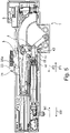
- the figures 5 , 6 show the ejector unit 1 in a discharged basic state of the energy accumulator 3, in which the spiral springs 10, 11 continue to be tensioned, but to a lesser extent, and have a length L1.
- the spiral springs 10, 11 In the clamped state of the force accumulator 3, the spiral springs 10, 11 have a length L2 which is greater than L1.
- a holding element 32 with the stop element 26 is present on the movement element 18 .
- the force accumulator 3 or the movement element 18 is operatively connected to the ejector 5, preferably only when the drawer 53 is closing - and moveable.
- a linear guide 20 is formed on the base plate 2, which z. B. on one side of the ejector 5 is matched.
- An opening process of the drawer 53 brought about by the ejector unit 1 takes place exclusively via a direct operative connection of the energy accumulator 3 via the movement element 18 moving in direction P2 to the ejector 5 .
- a stop element 26 is formed on the movement element 18, which is advantageously designed to be elastic and thus prevents or at least dampens a noise that is bothersome to a user when the movement element 18 hits the ejector 5 during the opening process of the drawer 53 ( figure 3 , 4 , 5 ).
- a front gap adjustment arrangement 8, which is formed on the ejector 5, comprises a housing 45 and an adjusting screw 22 with a contact section 21.
- the adjusting screw 22 has an external thread which cooperates with an internal thread on the housing 45.
- the adjusting screw 22 is in particular designed to be self-locking relative to the housing 45 .
- the contact section 21 of the adjusting screw 22 is in the clamped or loaded state of the force accumulator 3 on a driver 23, which forms a stop for the contact section 21 in corresponding operating states.
- Drivers 23, indicated only by dashed lines, can be present, for example, on a fixed rail of the guide means 52 or can be attached to the furniture body 51 if the ejector unit 1 is arranged on the drawer 53.
- the ejector unit 1 is arranged on the furniture body 51 or on a part of the guide means 52 of the furniture 50 which is fixed in position, then the driver 23 can be present on the drawer 53 and can therefore be movable relative to the furniture body 51 .
- the tensioned or loaded energy accumulator 3 pulls the movement element 18 in the direction P2, which presses or pushes the ejector 5 in the direction P2 relative to the base plate 2 via the stop element 26.
- a latch component 24 pivotably mounted on the ejector 5 of the ejector unit 1 is moved from a pivoted-in position completely countersunk in relation to an outer edge of the base plate 2 figure 4 brought into a swing-out position with a lug partially projecting over the outer edge of the base plate 2 ( figure 5 ), which is realized via a loop-shaped, closed guide track 25 in the base plate 2 and a guide pin 24a engaging therein on the pawl component 24.
- FIGS Figures 3 to 8 To show the pawl component 24, its outline, which is covered by other components, in particular by the ejector 5, is shown in FIGS Figures 3 to 8 indicated by dashed lines.
- the energy accumulator 3 In the basic state shown, the energy accumulator 3 is in an end position of the unloading state, with the energy accumulator 3 not being able to move the ejector 5 any further in the direction of P2.
- the ejector 5 is then moved in the direction P2 relative to the base plate 2 due to the kinetic energy of the drawer 53, which is caused by the previous ejection movement, and/or by a manual further movement of the drawer 53 in the opening direction M1 by a user.
- This is possible because the pawl component 24 pivoted out above the ejector 5 abuts the driver 23, whereby the ejector 5 reaches its end position, which is displaced as far as possible in the direction P2 on the base plate 2, in the further course of the drawer movement.
- the pawl component 24 is fully pivoted again upon reaching the end position on the ejector 5, which is due to the interaction of the guideway 25 with the engaging therein Guide pin 24a on the pawl component 24 is specified.
- the ejector unit 1 separates from the driver 23 and the contact between the driver 23 and the contact section 21 of the adjusting screw 22 is eliminated ( figure 6 ).
- the ejector 5 is pushed by spring elements 33 on the base plate 2, for example by a few millimeters in direction P1.
- the spring elements 33 have a comparatively small force.
- Bearing pin 31 is arranged at a first end of clamping lever 30 and can move freely along a linear guideway 27, for example, and/or a linear guide 63 formed on ejector 5, in particular during an opening process of drawer 53, until the pawl component 24 holds the bearing journal 31 and/or the tensioning lever 30 in direct, play-free contact with the ejector 5.
- the waiting position of the ejector 5, which figure 6 shown is also a starting position of the ejector 5 for a loading process of the energy store 3 via the coupling device 4.
- the coupling device 4 comprises a guide lever 34 and a connecting element 35.
- the clamping lever 30 is articulated at a second end via a bearing pin 36 on the guide lever 34.
- the connecting element 35 is at a second end via a bearing pin 36 spaced from the bearing pin 37 also on the guide lever 34 and articulated at its first end via a further bearing pin 38 on the moving element 18 .
- the guide lever 34 can be moved, in particular pivoted, on the base plate 2 via a bearing pin 39 .
- the bearing journal 39 is preferably accommodated both on the base plate 2 and on the cover component 9 .
- the guide lever 34 of the coupling device 4 comprises a lever attachment 40 at a second end.
- a locking element 41 and a stop element 42 are formed on the lever attachment 40 .
- the end position of the discharge state of the force accumulator 3 ( figure 5 ) is specified by a stop of the stop element 42 of the guide lever 34 on a wall section 47 on a web-like wall 48 of the base plate 2 .
- the wall section 47 is formed, for example, from an annular section of a damping element. If the stop element 42 of the guide lever 34 is in contact with the wall section 47 after the energy accumulator 3 has been discharged, a tensile force in direction P2 is transmitted from the moving element 18 via the connecting element 35 to the guide lever 34 due to the remaining pretension of the spiral springs 10, 11.
- stop element 42 and/or the wall section 47 can be designed to be elastic or dampening, with the result that impact noise is reduced or prevented.
- the guide lever 34 can transmit a force with a translation from the clamping lever 30 to the connecting element 35 when the energy store 3 is being clamped.
- the transmission ratio is formed on the one hand by the ratio of the distance between the bearing pins 39 and 36 and the distance between the bearing pins 39 and 37 on the guide lever 34, and on the other hand by the combined circular and linear movement of the clamping lever 30 and/or the connecting element 35 to one another during the loading process of the power store 4.
- the elements of the coupling device 4 can move as follows:
- the bearing pin 31 and thus the first end of the clamping lever 30 can only move parallel to a direction of movement of the ejector 5 , in particular parallel to a direction of movement of the movable furniture part 53 , due to its mounting in the guideway 27 .
- the bearing pin 38 and thus the first end of the connecting element 35 can only move parallel to a direction of movement of the movement element 18 or of the ejector 5, in particular parallel to the direction of movement of the movable furniture part 53 .
- the bearing pin 36 and thus the second end of the clamping lever 30 can only move in a circular path around a center of rotation of the bearing pin 39 of the guide lever 34 due to its mounting at the second end of the guide lever 34 .
- the bearing pin 37 of the connecting element 35 and thus the second end of the connecting element 35 can only move in a circular path around a center of rotation of the bearing pin 39 of the guide lever 34 due to its bearing in a central region of the guide lever 34 .
- the coupling device 4 can transmit a force for tensioning the energy store 3 from the ejector 5 via the tensioning lever 30 and the guide lever 34 to the connecting element 35 and thus to the energy store 3 in a translated manner; in particular, the coupling device 4 reduces the force exerted by the ejector 5 on the energy storage device 3. This means that when loading the energy storage device 3, a user has to apply less force to the ejector 5 than he would have to apply if he wanted to load the energy storage device 3 without a gear reduction or directly end 17 of the energy storage device 3 in would pull toward P1.
- the tensioning of the energy accumulator 3 takes place with a movement of the drawer 53 during the closing or on a section of the closing movement of the drawer 53 figure 6 .
- the ejector unit 1 moves towards the driver 23 in the direction M2. With the striking of the contact portion 21 of the screw 22 of the ejector 5 on Driver 23 begins the loading process of the energy accumulator 3. For example, due to the inertia of the drawer 53 relative to the base plate 2, the ejector 5 is moved in the direction P1 by hitting the driver 23.
- the movement element 18 of the energy store 3 is also displaced in the direction P1 relative to the base plate 2 and the second end 17 of the spiral springs 10, 11 is displaced in the direction P1 and thus the spiral springs 10 , 11 elongated.
- the ejector 5 At the end of the clamping process of the energy store 3, the ejector 5 is in a loading end position, this is in figure 7 shown. In the clamped state of the energy store 3, the ejector unit 1 is in a locked state.
- the locking element 41 of the coupling device 4 and the locking member 7, which is designed as a flap, determine a locking state, with an unloading movement of the coupling device 4 being blocked by the locking member 7.
- the tensioning of the energy accumulator 3 is fully completed before, for example, an automatic retraction mechanism for force-assisted retraction of the drawer 53 into the fully closed closed position on the furniture body 51 becomes effective.
- the automatic feed is not part of the ejector unit 1 and is integrated, for example, in the guide means 52 or the partial or full extensions.
- the ejector 5 is decoupled from the coupling device 4 and can be moved in the direction P1, in particular by an automatic retraction mechanism, until the drawer 53 is completely closed on the furniture body 51 and the ejector 5 on the trigger 6 is in the basic position according to FIG figure 3 pending.
- the ejector unit 1 In order to eject the drawer 53 with the ejector unit 1 from the fully pushed in or closed position on the furniture carcass 51, a user must exert pressure on the drawer from the outside in the direction M2.
- the ejector unit 1 has a so-called touch-latch functionality, which has a locked state that can be unlocked by moving the inserted drawer 53, which is closed on the furniture body 51, in the closing direction M2.
- This closing movement or the inward pressing of the drawer 53 in direction M2 takes place until a stop position is reached corresponding to a front gap which, when the drawer 53 is closed, is created in particular by a distance between an inside of the drawer front 55 and a front end face or the side walls 56 of the furniture carcass 51 is specified.
- the front gap is usually a few millimeters, for example about 1 to 10 millimeters.
- the unlocking of the ejector unit 1 is coordinated such that a closing movement of the drawer 53 in direction M2 of a few millimeters or at most by the amount of the front gap is sufficient to unlock and thus force-assisted ejection of the drawer 53 safely to pretend
- the ejector unit 1 with the drawer 53 is moved in the direction M2. Since the adjusting screw 22 is present on the driver 23, the ejector 5 is moved relative to the base plate 2 in the direction P1, whereby a contact section 44 on the ejector 5 presses against the trigger 6 and pushes it accordingly in the direction P1.
- the trigger 6 is present on the base plate 2 so that it can be displaced linearly to a limited extent in the direction P1 and P2, usually by a few millimeters or less than the dimension of the front gap.
- the trigger 6 is preferably coupled directly to the locking element 7, which is configured as a flap 43, in such a way that the linear triggering movement of the trigger 6 in direction P1 causes the flap 43 to rotate about a pivot axis D.
- the rotary movement releases the flap 43 from a locking position into which the flap 43 is urged by a spring element designed as a leaf spring 49 .
- the flap 43 In the locked state of the ejector unit 1, the flap 43, which is in the locking position, blocks the guide lever 34 or the lever attachment 40 in such a way that the energy store 3 remains in its charged state.
- the locking element 41 which is pretensioned by a torsion spring 60 , preferably pivots out on the lever attachment 40 .
- the locking element 41 projecting on the lever attachment 40 moves with the pivoting operation of the guide lever 34 below the flap 43 past the latter and continues the rotational movement of the flap 43 about the pivot axis D initiated by the trigger 6 without interruption.
- a rotation angle of the flap 43 from the locking position is advantageously increased.
- the locking element 41 is pivoted out again behind the flap 43 by the spring force of the torsion spring 60 . After the tensioning process, the guide lever 34 is pressed with the protruding locking element 41 against the flap 43 held in a locking manner by the leaf spring 49, as a result of which the energy store 3 is in the locked state.
- the rotational movement of the flap 43 of the ejector unit 1 or of the device 58 is transmitted via a synchronous rod 61, which is arranged in a rotationally fixed manner on the flap 43, to a second device 62, which advantageously has the same effect and is arranged on the drawer 53.
- the synchronizing rod 61 connects the locking member 7 to a second locking member present on the second device 62 .
- the two locking members are thus directly and/or synchronously movement-coupled. This represents a contrary synchronization principle to a connection between triggering elements of two ejector devices on a piece of furniture.
- figure 10 shows this in a perspective view from below Cover component 9 from figure 9 , which can be connected to the base plate 2 by plugging.
- the cover component 9 is designed as a fastening sheet metal 64 with a surface sheet metal section 70 and defined predefined edge shapes.
- the fastening plate 64 serves as a partial housing or to cover the ejector unit 1 on a main side of the ejector unit 1. With the help of the fastening plate 64, the ejector unit 1 is attached to the guide means 52 and/or the drawer 53. Depending on the attachment point of the ejector unit 1 on the piece of furniture 50 and in particular depending on the existing guide means 52, one of the appropriately designed fastening plates 64, 65 or 66 is used.
- Each of the fastening plates 64, 65 and 66 has connecting means which comprise prepared sections for attaching or attaching to the base plate 2, which differ from fastening plate to fastening plate or are different in each case.
- the sections are preferably designed in the edge areas of the respective fastening plate 64, 65 or 66.
- several prepared sections such as six spring tabs 67 are configured on the base plate 2 for connection to a cover component 9 or for interaction with associated matching connection means on the cover component 9 .
- the spring shackles 67 which are bent over like a hook here, can spring in somewhat elastically when the cover component 9 is pushed onto the base plate 2 .
- each spring tab 67 is on an associated window-like one Recess 68 is snapped into the cover component 9, the base plate 2 and the cover component 9 being able to be latched together at several points, or in this case six points, in accordance with the number of spring tabs 67.
- the mounting plates 64, 65 and 66 each have the recesses 68 at the corresponding points. Thus, each of the fastening plates 64, 65 and 66 can be connected to the base plate 2 in the same way.
- the attachment of the ejector unit 1, which is assembled as explained above from the base plate 2 and one of the fastening plates 64, 65 and 66, to a piece of furniture and/or the guide means 52 can be set up using plug-in, screw, snap-in, adhesive and/or other types of connection .
- the fastening plates 64, 65 and 66 have screw holes 69 in common for screwing means, not shown, to pass through for screwing, for example on the underside of the drawer bottom 54.
- the screw holes 69 are present on a first longitudinal side of the fastening plates 64, 65 and 66 on a lug 71, which protrudes laterally via two right-angled bends on the surface sheet metal section 70 offset parallel to the surface sheet metal section 70.
- a further tab 72 with a screw hole 73 is formed on the fastening plate 66 at the level of the surface plate section 70 .
- the connecting means on the cover component 9 include a web 74 here at the fastening plates 65 and 66.
- the web 74 is over the substantial length of the mounting plates 65 and 66 with two spaced laterally projecting tongues 75 designed.
- the web 74 is present on the longitudinal side of the fastening plates 65 and 66 opposite the lug 71 and offset parallel to the surface plate section 70 by bending.
- the tongues 75 can, for example, clamp in correspondingly fitting recesses on the guide means, for example a carcass rail and/or the side wall of the drawer 53.
- Two spaced-apart protruding tongues 76 are also formed on the fastening plate 66 on the associated longitudinal edge of the surface plate section 70 .
- Screw holes 77 are also provided in web 74 .
- the connecting means On the fastening plate 64, which has no web 74, the connecting means have comparatively narrow hook-like tabs 78 and 79.
- the mounting plate 65 is designed to be inserted countersunk into a recessed cut-out on the underside of the drawer bottom 54 . Therefore, the web 74 is offset further according to the depth of the milled cut-out to the surface sheet metal section 70 . As a result, the tongues 75 are formed at the level of the underside of the drawer bottom for engagement in associated areas.
- the ejector unit 1 can then, for example, be completely lowered on the drawer bottom 54.
- connection of the ejector unit 1 by means of the tongues 75, 76 and the tabs 78, 79 is preferably carried out without tools.
Landscapes
- Engineering & Computer Science (AREA)
- Mechanical Engineering (AREA)
- Drawers Of Furniture (AREA)
- Closing And Opening Devices For Wings, And Checks For Wings (AREA)
Description
- Bei Möbelteilen wie zum Beispiel Schubladen, Möbeltüren oder Möbelklappen, die an einem Möbelkorpus eines Möbels über Führungsmittel bewegbar aufgenommen sind, kommen Vorrichtungen zur Bewegungsbeeinflussung des Möbelteils zum Einsatz.
- Derartige Vorrichtungen sind z.B. durch eine Einheit gebildet, die an dem Möbelteil, dem Möbelkorpus oder den Führungsmitteln an geeigneter Stelle anbringbar ist.
- Die Führungsmittel umfassen insbesondere eine Schiebeführung wie einen Voll- oder Teilauszug oder eine Schwenkführung wie ein Möbelscharnier.
- Bei modernen und bedienerfreundlichen Möbeln sind beispielsweise Vorrichtungen für die Bewegung des Möbelteils bekannt, die zur Bereitstellung einer Zusatzfunktion wahlweise vorgesehen werden können, insbesondere um einem Nutzer das Öffnen des Möbelteils zu erleichtern. Die Zusatzfunktion ist insbesondere auf die Art und Größe des Möbelteils abstimmbar. Die Vorrichtung zur Bewegungsbeeinflussung des Möbelteils betrifft z. B. Systeme zur Bereitstellung einer kraftunterstützten Öffnungsfunktion für das Möbelteil. Die Art der Anbindung der Vorrichtung muss hierbei jeweils berücksichtigt werden.
- Die
DE 10 2010 036 903 A1 betrifft eine Ausstoßvorrichtung und Auszugsystem. DieAT 508 139 A4 DE 10 2010 031 940 A1 und dieWO 2007/087656 A1 sind ebenfalls zum Stand der Technik zu zählen. Aufgabe und Vorteile der Erfindung - Aufgabe der vorliegenden Erfindung ist es, eine Zusatzfunktion für eine Möbelteilbewegung bzw. ein entsprechendes Möbel mittels einer Schiebeführung, wie einen Voll- oder Teilauszug oder einer Schwenkführung, vorteilhaft bzw. flexibel anordenbar bereitzustellen. Diese Aufgabe wird durch den unabhängigen Anspruch gelöst.
- Die abhängigen Ansprüche thematisieren vorteilhafte Varianten der Erfindung.
- Die Erfindung geht aus von einer Vorrichtung zum Bewegung eines bewegbaren Möbelteils in eine Öffnungsrichtung des Möbelteils in Bezug zu einem Möbelkorpus eines Möbels, wobei das bewegbare Möbelteil über Führungsmittel in die Öffnungsrichtung und in eine der Öffnungsrichtung entgegengesetzte Schließrichtung bringbar ist, wobei die Vorrichtung ein Basisbauteil umfasst, an dem ein Kraftspeicher vorhanden ist, so dass mit der montierten Vorrichtung das bewegbare Möbelteil unter der Wirkung des Kraftspeichers in die Öffnungsrichtung des bewegbaren Möbelteils bringbar ist.
- Weiter ist ein zum Basisteil passend ausgebildetes separates Abdeckbauteil der Vorrichtung vorhanden, welches das Basisbauteil abdeckt, wobei Verbindungsmittel am Abdeckbauteil derart ausgebildet sind, dass eine Anbindung der Vorrichtung an einem Gegenabschnitt am Möbel und/oder den Führungsmitteln mit den am Abdeckbauteil vorhandenen Verbindungsmitteln einrichtbar ist. Damit lässt sich eine vorteilhafte, platzsparende und montagefreundliche
- Anbindung der Vorrichtung realisieren. Insbesondere ist das Abdeckbauteil als separates Element mit dem Basisbauteil verbindbar. Das Abdeckbauteil ist lösbar oder unlösbar mit dem Basisbauteil verbunden, insbesondere unlösbar am Basisbauteil angesteckt.
- Ausgehend von einem universell verwendbaren Basisbauteil können daran unterschiedliche Varianten eines Abdeckbauteils für die Anbindung an unterschiedlichen Gegenabschnitten wie z. B. jeweils unterschiedliche Führungsmittel bereitgestellt werden. Mit dem z. B. jeweils zu den verwendeten Führungsmitteln passenden Abdeckbauteil ist daher genau eine Ausbildungsform des Basisbauteils ausreichend, um die Vorrichtung an verschiedenen Varianten von Führungsmitteln anbinden zu können. Bei der Fertigstellung der Vorrichtung muss ausgehend von dem Basisbauteil dann lediglich die jeweilige Variante des Abdeckbauteils ausgewählt und mit dem Basisbauteil verbunden werden.
- Jede Variante des Abdeckbauteils passt zu dem Basisbauteil, so dass der Zusammenbau des Basisbauteils und des dazu ausgewählten Abdeckbauteils vorteilhaft gleichartig erfolgt. Die am jeweiligen Abdeckbauteil individuellen Verbindungsabschnitte unterscheiden sich bei den einzelnen Varianten der Abdeckbauteile. Die Unterschiede sind vorzugsweise allein in den Verbindungsmitteln am Abdeckbauteil vorhanden.
- Am Basisbauteil sind die grundlegenden Funktionen der Vorrichtung realisiert. Zudem deckt das Abdeckbauteil das Basisbauteil zumindest einseitig ab, womit ein Schutz gegen Verschmutzung und/oder Beschädigung der Vorrichtung mit dem Abdeckbauteil realisiert ist.
- Mit dem Abdeckbauteil erfolgt z. B. eine einseitig flächige und zumindest teilweise randseitige Abdeckung insbesondere eines Innenbereichs der Vorrichtung. Die andere flächige Seite der Vorrichtung ist mit einer Wand des Basisbauteils bzw. einer flächigen Seite des Basisbauteils nach außen abgeschlossen.
- Über eine vergleichsweise schmale Höhe der Vorrichtung können Abschnitte des Abdeckbauteils und/oder Abschnitte des Basisbauteils die Außenseite der Vorrichtung bilden auch ggf. überlappend. Diese Abschnitte sind insbesondere rechtwinklig zu einer Hauptflächenseite des Basisbauteils bzw. des Abdeckbauteils gebildet.
- Das Abdeckbauteil ist insbesondere aus einem flachen Blechbauteil durch Ausnehmungen und Umbiegungen gebildet. Alternativ ist das Abdeckbauteil aus einem Kunststoffmaterial.
- Die Vorrichtung ist vorzugsweise als Auswerfereinheit ausgebildet mit einem bei einer Schließbewegung des Möbelteils ladbaren Kraftspeicher. Der geladene bzw. gespannte Kraftspeicher wird mit einem Auslösevorgang aus einer verriegelten Position gelöst, so dass unter der Wirkung der vom Kraftspeicher bereitgestellten Kraft das Möbelteil aus der geschlossenen Anordnung am Möbelkorpus etwas in Öffnungsrichtung herausbewegt wird. An der Vorrichtung bzw. dem Basisbauteil sind vorzugsweise eine Auslöseeinheit mit Touch-Latch-Funktion, eine Auswerfanordnung, eine Verriegelung des gespannten Kraftspeichers und ein Lademechanismus für den Kraftspeicher vorhanden.
- Weiter ist es erfindungsgemäß, dass das Abdeckbauteil einen flächigen Abschnitt aufweist, der sich über eine wesentliche Erstreckung des Abdeckbauteils erstreckt. Der flächige Abschnitt dehnt sich auf einer Fläche aus, welche insbesondere eben ausgestaltet ist. Der flächige Abschnitt bildet insbesondere eine Außenseite der Vorrichtung, welche gegenüberliegend zu einer Außenseite ist, die vom Basisbauteil gebildet ist. Das Abdeckbauteil ist insbesondere einstückig aus einem Material gebildet, insbesondere aus einem Blech gebildet.
- Das Abdeckbauteil ist vergleichsweise dünn, mit vorzugsweise gleichbleibender Wandstärke, beispielsweise von ein bis zwei Millimetern. Am Abdeckbauteil, z. B. innerhalb einer Umrandung und/oder am Randverlauf, sind an vorgegebenen Stellen Ausschnitte, Öffnungen, Schlitze, Stege und/oder Umbiegungen vorhanden.
- Auch ist es von Vorteil, dass das Abdeckbauteil eine Anlageseite aufweist, welche für eine flächige Anlage an einer Anbringfläche des Möbels ausgebildet ist, wenn die Vorrichtung am Möbel montiert ist. Die Anbringfläche des Möbels ist insbesondere flach und eben. Die Anlageseite ist vorzugsweise dem Flächenabschnitt des Abdeckbauteils zugehörig. Die aus dem Basisbauteil und dem Abdeckbauteil zusammengesetzte Vorrichtung kann am Möbel bzw. einer flächigen Gegenseite am Möbel bzw. des Möbelteils vorteilhaft angeordnet werden. Die Vorrichtung kann zum Beispiel mit der Anlageseite an einer ebenen, flachen Unterseite eines Schubladenbodens anliegend angebracht werden. Gemäß einer vorteilhaften Erfindungsvariante ist das Abdeckbauteil ausgestaltet, eine Hauptseite des Basisbauteils zumindest annähernd komplett abzudecken. Damit wird eine offene Seite bzw. das Innere des Basisbauteils nach außen abgeschlossen bzw. geschützt.
- Überdies ist es erfindungsgemäß, dass das Abdeckbauteil einen Randabschnitt aufweist, welcher sich über eine Umbiegung an einen flächigen Abschnitt des Abdeckbauteils anschließt. Insbesondere ist die Umbiegung am Abdeckbauteil rechtwinklig zum benachbarten Flächenabschnitt vorhanden. Vorzugsweise sind mehrere unterschiedlich gestaltete Randabschnitte, die sich am Flächenabschnitt anschließen, möglich. Auch zweifach oder mehrfach umgebogene Randabschnitte, insbesondere jeweils rechtwinklig umgebogene Randabschnitte, sind denkbar. Sämtliche Umbiegungen stehen an der Anlageseite vorzugsweise in die gleiche Richtung ab, so dass die Anlageseite des Abdeckbauteils ohne Erhöhungen bzw. Überstände gebildet ist.
- Das Basisbauteil bzw. dessen Randabschnitt ist auf den Randabschnitt des Abdeckbauteils derart abgestimmt, dass im zusammengesetzten Zustand der Vorrichtung die Randabschnitte sich so ergänzen, dass die Vorrichtung einen vorgegeben Randverlauf aufweist, insbesondere überwiegend oder komplett innerhalb des Randverlaufs des Basisbauteils aufgenommen bzw. nach außen abgeschlossen ist.
- Der Randabschnitt des Abdeckbauteils und/oder des Basisbauteils weist einen Randverlauf auf, der auf unterschiedliche Weise ausbildbar ist, z. B. ohne oder mit Umbiegung, geradlinig oder konturiert, konvex oder konkav gebogen und dergleichen. Erfindungsgemäß ist eine Schmalseite des Basisbauteils von einem umgebogenen Randabschnitt des Abdeckbauteils abgedeckt sind. So können schmale Seiten des von dem Abdeckbauteil abgedeckten Basisbauteils, zum Beispiel über eine Höhenabmessung des Basisbauteils gegen Schmutz bzw. Feuchtigkeit geschützt werden.
- Erfindungsgemäß weist das Abdeckbauteil einen Randabschnitt mit einer zu benachbarten Randabschnitten nach außen vorstehenden Kontur auf. Vorzugsweise umfassen die Verbindungsmittel den Randabschnitt mit der vorstehenden Kontur. Der vorstehende Randabschnitt dient zur Verbindung der Vorrichtung an Gegenabschnitten insbesondere von Führungsmitteln. Die betreffenden Randabschnitte sind abgestimmt ausgestaltet auf passend vorhandene Gegenabschnitte. Die Form bzw. Kontur des vorstehenden Randabschnitts ist z.B. laschen, streifen und/oder zungenartig. Der Randabschnitt mit der nach außen vorstehenden Kontur weist vorzugsweise winklige zueinander ausgerichtete Außenseiten auf. Im Verbindungszustand sind die Randabschnitte mit der nach außen vorstehenden Kontur
verklemmt, verrastet und/oder eingeclipst an dem dazugehörigen Gegenabschnitt an den Führungsmitteln und/oder dem Möbel. Vorzugsweise weisen die Verbindungsmittel Krallen- oder Hakenmittel auf zum Verkrallung bzw. Einhaken in einem nachgiebigen Material wie einem Holzmaterial des Möbels oder des Möbelkorpus. - Eine vorteilhafte Modifikation der Erfindung ist dadurch gekennzeichnet, dass die Verbindungsmittel am Abdeckbauteil derart ausgebildet sind, dass eine Anbindung der Vorrichtung an einem Gegenabschnitt am Möbel und/oder den Führungsmitteln werkzeuglos einrichtbar ist. Dies ist für die Montage der Vorrichtung vorteilhaft.
- Eine vorteilhafte Ausbildung der Erfindung ist dadurch gebildet, dass das Abdeckbauteil und das Basisbauteil derart aufeinander abgestimmt sind, dass im verbundenen Zustand des Abdeckbauteils und des Basisbauteils ein Abschnitt des Basisbauteils auf einer Schmalseite der Vorrichtung nach außen heraussteht. Insbesondere sind das Basisbauteil und das Abdeckbauteil mit einer korrelierenden Ausnehmung an einem gemeinsamen Randabschnitt ausgebildet. Vorzugsweise kann im Bereich der gebildeten Lücke aus der Schmalseite der Vorrichtung ein Bedienabschnitt einer Einstellanordnung der Vorrichtung herausstehen. Damit ist der Bedienabschnitt von außen von einer Person erreichbar, um manuell auf die Vorrichtung einzuwirken. Beispielsweise kann auf diese Weise eine Vorspannung des Kraftspeichers fest eingestellt werden, was abhängig von der zu bewegenden Masse des Möbelteils erfolgt.
- Zudem ist es von Vorteil, dass die Verbindungsmittel für eine lösbare Verbindung mit den Führungsmitteln des bewegbaren Möbelteils ausgebildet sind. Hier kommt insbesondere eine Verbindung mit einer Festschiene bzw. einer Korpusschiene eines Vollauszugs, z.B. eine Steckverbindung mit der Korpusschiene in Frage. Die Verbindungsmittel sind vorzugsweise so gestaltet, dass eine hohe Abstützwirkung der Vorrichtung an den Führungsmitteln möglich ist.
- Darüber hinaus ist es auch von Vorteil, dass das Abdeckbauteil für eine Anbringung der Vorrichtung an einer Unterseite einer Schublade ausgebildet ist. Vorzugsweise erfolgt zusätzlich zur Anbringung an der Schubladenunterseite die Anbringung der Vorrichtung an einer Schubladenseitenwand, zum Beispiel an einem Dekor einer Hohlkammerzarge der Schublade.
- Auch ist es von Vorteil, dass das Abdeckbauteil für eine Anbindung der Vorrichtung im Bereich eines vertieft ausgebildeten Bereichs an dem Möbel ausgebildet ist. Dies ermöglicht eine besonders platzsparende Anbringung an einem Möbelteil oder dem Möbelkorpus. Das Abdeckbauteil liegt im montierten Zustand vorzugsweise mit einer Außenseite auf dem Boden der vertieften Ausnehmung auf. Vorzugsweise reicht am Rand der Ausnehmung ein entsprechender Teil mit einem Absatz des Abdeckbauteils aus der Vertiefung heraus zur Anbringung der Vorrichtung an den Führungsmitteln, wie einer Festschiene der Führungsmittel, und/oder an Teilen des Möbelteils, beispielsweise an einer Seitenwand der Schublade.
- In der Regel ist eine Wandstärke des Möbelteils größer als eine Höhe der Vorrichtung, so dass eine Reststärke der Wand verbleibt und einen Boden der Vertiefung bildet. Der vertieft ausgebildete Bereich ist vorzugsweise an die Höhe der Vorrichtung angepasst, so dass die Vorrichtung insbesondere komplett bzw. bündig versenkt im vertieften Bereich einbringbar bzw. versenkbar ist, zum Beispiel an einer Unterseite eines Schubladenbodens. Die Vorrichtung kann alternativ mit einem geringen Überstand zur Möbelteilwandung in der Vertiefung untergebracht sein. Die Vertiefung ist beispielsweise streifenförmig und nut- oder kanalartig bzw. insbesondere auf die Größe und/oder Form der Vorrichtung abgestimmt.
- Bei einer vertieften Ausnehmung in einer Unterseite eines Schubladenbodens ist die Vertiefung vorzugsweise zu einem rückwärtigen Rand des Schubladenbodens offen über die Breite der Ausnehmung, jedoch zu einem seitlichen Längsrand des Schubladenbodens geschlossen.
- Die Erfindung erstreckt sich außerdem auf ein Möbel mit einem Möbelkorpus und einem bewegbaren Möbelteil, das über Führungsmittel in eine Öffnungsrichtung des Möbelteils und in eine der Öffnungsrichtung entgegengesetzte Schließrichtung relativ zu dem Möbelkorpus bringbar ist, wobei eine Vorrichtung nach einem der oben erläuterten Ausbildungen vorgesehen ist. Damit lassen sich die erläuterten Vorteile an dem Möbel realisieren. Insbesondere ist das Möbel mit einer Führung bzw. mit Führungsmitteln gemäß eines Vollauszuges oder Teilauszuges ausgebildet, wobei im Vollauszug oder Teilauszug eine Einzugsautomatik zum Einziehen des Möbelteils in eine vollständig geschlossene Position kraftunterstützt möglich ist. Auch ist vorteilhaft eine Synchronisation der sogenannten Touch-Latch-Funktionalität bei zwei seitlichen Führungseinheiten vorgesehen. Das Möbelteil ist z.B. eine Schublade, welche über zwei seitlich vorhandene Vollauszüge verschieblich an den gegenüberliegenden Korpuswänden des Möbelkorpus aufgenommen ist.
- Wenn eine Vertiefung in einem Schubladenboden unterseitig zur Einsetzung der Vorrichtung vorhanden ist, ist vorzugsweise der Teil der Vertiefung, welcher nicht von der Vorrichtung belegt ist, durch ein entsprechendes Abdeckelement auf der Höhe der Unterseite des Schubladenbodens abgedeckt. Alternativ kann eine Verlängerung am Abdeckbauteil den Rest der Vertiefung abdecken.
- Weitere Merkmale und Vorteile der Erfindung sind anhand von in den Figuren schematisiert dargestellten Ausführungsbeispielen näher erläutert.
- Im Einzelnen zeigt:
- Figur 1
- ein erfindungsgemäßes Möbel perspektivisch von schräg oben mit einer Schublade im vollständig geöffneten Zustand an einem Möbelkorpus,
- Figur 2
- eine erfindungsgemäße Vorrichtung ohne ein Abdeckbauteil in Explosionsdarstellung,
- Figuren 3 bis 8
- die Vorrichtung gemäß
Figur 2 im zusammengesetzten Zustand in einer Aufsicht einer ersten Hauptseite in unterschiedlichen Betriebszuständen, - Figur 9
- die Vorrichtung gemäß
Figur 5 mit einem Abdeckbauteil perspektivisch schräg von unten mit Blick auf eine zweite Hauptseite der Vorrichtung, - Figur 10
- das Abdeckbauteil gemäß
Figur 9 in Unteransicht und - Figur 11 und 12
- eine jeweils perspektivische Unteransicht von alternativen Abdeckbauteilen.
- Ein erfindungsgemäßes Möbel 50 mit einem kastenförmigen Möbelkorpus 51 und einer über Führungsmittel 52 beweglich geführten Schublade 53 ist in
Figur 1 dargestellt. Die Schublade 53 umfasst einen Schubladenboden 54, eine Schubladenfront 55, zwei gegenüberliegende Seitenwände 56 und eine Schubladenrückwand 57. Für die Führung der Schublade 53 sind zwei gleichwirkende Führungsmittel 52 jeweils zwischen jeder Seitenwand 56 der Schublade 53 und einer dazugehörigen Korpusseitenwand 59 vorhanden. An einer Unterseite des Schubladenbodens 54 ist eine erfindungsgemäße Vorrichtung 58 (gestrichelt dargestellt) zum Bewegen bzw. Auswerfen des als Schublade 53 ausgebildeten Möbelteils in Öffnungsrichtung M1 angeordnet. -
Figur 2 zeigt die Explosionsdarstellung der Vorrichtung 58, welche als Auswerfereinheit 1 für die Schublade 53 ausgebildet ist. - Die Auswerfereinheit 1 dient zum kraftunterstützten Auswerfen der Schublade 53 über eine erste Teilstrecke der Öffnungsbewegung der Schublade 53 aus einer geschlossenen Stellung relativ zum Möbelkorpus 51 in die Öffnungsrichtung M1 der Schublade 53.
- Die Schublade 53 ist über die Führungsmittel 52, beispielsweise zwei gleichartige Teil- oder Vollauszüge, am Möbelkorpus 51 in Richtung M1 und M2 verschiebbar gelagert. Die Auswerfereinheit 1 kann alternativ am Möbelkorpus 51 oder an den Führungsmitteln 52 des Möbels 50 angeordnet sein.
- Die Auswerfereinheit 1 umfasst unter anderem eine Grundplatte 2, einen Kraftspeicher 3, eine Kopplungseinrichtung 4, einen Auswerfer 5, ein als Auslöser 6 ausgebildetes Auslöseelement und ein Verriegelungsorgan 7.
- Ein Gehäuse der Auswerfereinheit 1 umfasst die Grundplatte 2 und ein Abdeckbauteil 9, welches aus
Figur 9 ersichtlich ist. Die Auswerfereinheit 1 kann über das Gehäuse bzw. über das Abdeckbauteil 9 und/oder die Grundplatte 2 an der Unterseite des Schubladenbodens 54 und/oder an den Führungsmitteln 52 angeordnet sein. - An der Grundplatte 2 sind Halteabschnitte, Führungskonturen, Anschlagsorgane und/oder Aufnahmeabschnitte zur Anbindung der einzelnen Komponenten der Auswerfereinheit 1 ausgebildet. Die Grundplatte 2 ist im Wesentlichen als rechteckiges, längliches bzw. streifenförmiges Bauteil mit einer vergleichsweise geringen Höhe h von zum Beispiel zirka 5 bis 15 Millimeter ausgestaltet. Die Grundplatte 2 weist des Weiteren eine Breite b von zirka 4 bis 10 Zentimeter und eine Länge g auf.
- Der Kraftspeicher 3 umfasst gemäß des gezeigten Ausführungsbeispiels zwei parallel angeordnete gleichartige Spiralfedern 10, 11, die ein Federpaket ausbilden. An einem ersten Ende 12 des Kraftspeichers 3 sind die Spiralfedern 10, 11 an einem einstellbaren Festlager 13 angeordnet. Das Festlager 13 umfasst ein bewegbares Lagerteil 14, an welchem die Spiralfedern 10, 11 lösbar aber fest aufgenommen sind und ein Stellteil 15 mit einem Bedienabschnitt 16, über welchen ein Nutzer von außen eine Position des Endes 12 des Kraftspeichers 3 veränderlich positionsfest einstellen kann. Hierdurch kann vorteilhaft eine Kraftwirkung des Kraftspeichers 3 auf die Schublade 53 beim Öffnungsvorgang der Schublade 53 voreingestellt werden.
- An einem zweiten Ende 17 des Kraftspeichers 3 sind die dazugehörigen Enden der Spiralfedern 10, 11 an einem schlittenartigen Bewegungselement 18 befestigt. Das schlittenartige Bewegungselement 18 ist über eine dazugehörige Führungskontur 19 an der Grundplatte 2 beweglich in eine Bewegungsrichtung P1 und eine entgegengesetzte Bewegungsrichtung P2 linear geführt.
- Die Bewegungsrichtungen P1 und P2 des Bewegungselements 18 (s.
Figuren 2 ,3 ) verlaufen parallel zu der Öffnungsrichtung M1 der Schublade 53 und einer dazu entgegengesetzten Schließrichtung M2. - Ist die Auswerfereinheit 1 positionsfest am Möbelkorpus 51 und/oder an einem stationären Teil der Führungsmittel 52 angeordnet, entspricht die Öffnungsrichtung der Schublade 53 der Richtung P1 und die Schließrichtung der Schublade 53 der Richtung P2.
- Im Weiteren wird von einem Montagezustand der Auswerfereinheit 1 am Schubladenboden 54 ausgegangen.
- Die
Figuren 3 ,7 ,8 zeigen die Auswerfereinheit 1 in einem Spannzustand des Kraftspeichers 3, in welchem die Spiralfedern 10, 11 gelängt bzw. auf Zug beansprucht gespannt sind, hierbei ist das Bewegungselement 18 gegenüber einer in Richtung P2 zurückgezogenen Stellung an der Grundplatte 2 in Richtung P1 versetzt und in einer Spannposition festgehalten.
DieFiguren 5 ,6 zeigen die Auswerfereinheit 1 in einem entladenen Grundzustand des Kraftspeichers 3, in welchem die Spiralfedern 10, 11 weiterhin auf Zug, jedoch mit einem geringeren Betrag, vorgespannt sind und eine Länge L1 aufweisen. - Im Spannzustand des Kraftspeichers 3 weisen die Spiralfedern 10, 11 eine Länge L2 auf, welche größer als L1 ist.
- Am Bewegungselement 18 ist ein Halteorgan 32 mit dem Anschlagselement 26 vorhanden.
- Über die Kopplungseinrichtung 4 steht der Kraftspeicher 3 bzw. das Bewegungselement 18 vorzugsweise ausschließlich beim Schließvorgang der Schublade 53 in Wirkverbindung mit dem Auswerfer 5. Der Auswerfer 5 ist insbesondere ausschließlich linear bewegbar bzw. parallel zur Bewegungsrichtung des Bewegungselements 18 in die Richtungen P1 und P2 hin- und her bewegbar. Hierfür ist eine Linearführung 20 an der Grundplatte 2 ausgebildet, welche auf Führungsabschnitte z. B. auf einer Seite des Auswerfers 5 abgestimmt ist.
- Ein von der Auswerfereinheit 1 bewirkter Öffnungsvorgang der Schublade 53 findet ausschließlich über eine direkte Wirkverbindung des Kraftspeichers 3 über das sich in Richtung P2 bewegende Bewegungselement 18 auf den Auswerfer 5 statt. Hierfür ist am Bewegungselement 18 ein Anschlagselement 26 ausgebildet, welches vorteilhaft elastisch ausgestaltet ist und damit ein für einen Nutzer störendes Geräusch beim Auftreffen des Bewegungselements 18 auf den Auswerfer 5 im Öffnungsvorgang der Schublade 53 verhindert oder zumindest dämpft (
Figur 3 ,4 ,5 ). - Eine Frontspalt-Einstellanordnung 8, welche am Auswerfer 5 ausgebildet ist, umfasst ein Gehäuse 45 und eine Stellschraube 22 mit einem Kontaktabschnitt 21. Die Stellschraube 22 weist ein Außengewinde auf, welches mit einem Innengewinde am Gehäuse 45 zusammenwirkt. Durch manuelles Drehen eines Bedienabschnitts 46 der Stellschraube 22 durch einen Nutzer ist abhängig von der Drehrichtung eine Position des Kontaktabschnitts 21 der Stellschraube 22 in Richtung P1 oder P2 verstellbar. Die Stellschraube 22 ist insbesondere selbsthemmend relativ zum Gehäuse 45 ausgebildet. Durch die Positionsvorgabe der Stellschraube 22 ist ein Maß eines Frontspalts zwischen der Schubladenfront 55 der am Möbelkorpus 51 geschlossenen Schublade 53 und Stirnseiten des Möbelkorpus 51 vorgebbar.
- Der Kontaktabschnitt 21 der Stellschraube 22 steht im gespannten bzw. geladenen Zustand des Kraftspeichers 3 an einem Mitnehmer 23 an, welcher in entsprechenden Betriebszuständen einen Anschlag für den Kontaktabschnitt 21 bildet. Der in den
Figuren 3 bis 8 lediglich gestrichelt angedeutete Mitnehmer 23 kann zum Beispiel an einer Festschiene der Führungsmittel 52 vorhanden sein oder am Möbelkorpus 51 angebracht sein, wenn die Auswerfereinheit 1 an der Schublade 53 angeordnet ist. - Ist die Auswerfereinheit 1 hingegen am Möbelkorpus 51 oder an einem positionsfesten Teil der Führungsmittel 52 des Möbels 50 angeordnet, so kann der Mitnehmer 23 an der Schublade 53 und damit beweglich zum Möbelkorpus 51 vorhanden sein.
- Wird ausgehend von der Grundstellung der Auswerfereinheit 1 gemäß
Figur 3 eine Arretierung an der Auswerfereinheit 1 aufgehoben, wasFigur 4 zeigt und weiter unten noch näher erklärt ist, zieht der gespannte bzw. geladene Kraftspeicher 3 das Bewegungselement 18 in Richtung P2, das über das Anschlagselement 26 den Auswerfer 5 in Richtung P2 relativ zur Grundplatte 2 drückt bzw. schiebt. - Sobald sich der Auswerfer 5 an der Grundplatte 2 in Richtung P2 bewegt, wird ein schwenkbar am Auswerfer 5 gelagertes Klinkenbauteil 24 der Auswerfereinheit 1 aus einer zu einem Außenrand der Grundplatte 2 vollständig versenkten Einschwenkstellung gemäß
Figur 4 in eine mit einer Nase teilweise über den Außenrand der Grundplatte 2 vorstehende Ausschwenkstellung gebracht (Figur 5 ), was über eine schleifenförmig geschlossenen Führungsbahn 25 in der Grundplatte 2 und einen darin eingreifenden Führungszapfen 24a am Klinkenbauteil 24 realisiert ist. - Zur Darstellung des Klinkenbauteils 24 ist dessen durch andere Bauteile, insbesondere durch den Auswerfer 5 verdeckter Umriss in den
Figuren 3 bis 8 gestrichelt angedeutet. - In dem in
Figur 5 dargestellten Grundzustand befindet sich der Kraftspeicher 3 in einer Endstellung des Entladezustands, wobei der Kraftspeicher 3 den Auswerfers 5 nicht weiter in Richtung P2 bewegen kann. - Der Auswerfer 5 wird anschließend aufgrund der Bewegungsenergie der Schublade 53, was bedingt durch die vorausgegangene Auswerfbewegung ist, und/oder durch ein manuelles Weiterbewegen der Schublade 53 in Öffnungsrichtung M1 durch einen Nutzer, in Richtung P2 relativ zur Grundplatte 2 verschoben. Dies ist deshalb möglich, weil das am Auswerfer 5 vorstehend herausgeschwenkte Klinkenbauteil 24 am Mitnehmer 23 anstößt, womit im weiteren Schubladen-Bewegungsverlauf der Auswerfer 5 seine maximal weit in Richtung P2 an der Grundplatte 2 verschobene Endstellung erreicht. Das Klinkenbauteil 24 wird mit Erreichen der Endstellung am Auswerfer 5 wieder vollkommen eingeschwenkt, was durch das Zusammenspiel der Führungsbahn 25 mit dem darin eingreifenden Führungszapfen 24a am Klinkenbauteil 24 vorgegeben ist.
- Wird die Schublade 53 nach einem Entladevorgang des Kraftspeichers 3 weiter in Öffnungsrichtung M1 bewegt, trennt sich die Auswerfereinheit 1 vom Mitnehmer 23 und der Kontakt zwischen dem Mitnehmer 23 und dem Kontaktabschnitt 21 der Stellschraube 22 wird aufgehoben (
Figur 6 ). - Aus der oben beschriebenen Endstellung, die der Auswerfer nur kurzzeitig einnimmt, wird der Auswerfer 5 durch Federelemente 33 an der Grundplatte 2 zum Beispiel um wenige Millimeter in Richtung P1 gedrängt. Die Federelemente 33 besitzen gegenüber den Spiralfedern 10, 11 des Kraftspeichers 3 eine vergleichsweise geringe Kraft. Mit der Bewegung des Auswerfers 5 in Richtung P1 durch die Kraft der Federelemente 33 wird ein Anlageabschnitt 29 des Klinkenbauteils 24 in einer Warteposition des Auswerfers 5 in direkten, spielfreien Kontakt mit einem Lagerzapfen 31 eines Spannhebels 30 der Kopplungseinrichtung 4 gebracht (
Figur 6 ). Der Lagerzapfen 31 ist an einem ersten Ende des Spannhebels 30 angeordnet und kann sich entlang einer zum Beispiel linearen Führungsbahn 27 und/oder einer Linearführung 63, welche am Auswerfer 5 ausgebildet ist, so lange frei bewegen, insbesondere innerhalb eines Öffnungsvorgangs der Schublade 53, bis das Klinkenbauteil 24 den Lagerzapfen 31 und/oder den Spannhebel 30 in direkten, spielfreien Kontakt mit dem Auswerfer 5 hält. - Die Warteposition des Auswerfers 5, welche in
Figur 6 gezeigt ist, ist auch gleichzeitig eine Startposition des Auswerfers 5 für einen Ladevorgang des Kraftspeichers 3 über die Kopplungseinrichtung 4. - Die Kopplungseinrichtung 4 umfasst neben dem Spannhebel 30, einen Führungshebel 34 und ein Verbindungselement 35. Der Spannhebel 30 ist an einem zweiten Ende über einen Lagerzapfen 36 am Führungshebel 34 angelenkt. Das Verbindungselement 35 ist an einem zweiten Ende über einen zum Lagerzapfen 36 beabstandeten Lagerzapfen 37 ebenfalls am Führungshebel 34 und an seinem ersten Ende über einen weiteren Lagerzapfen 38 am Bewegungselement 18 angelenkt. Der Führungshebel 34 ist an einem ersten Ende über einen Lagerzapfen 39 bewegbar, insbesondere schwenkbar an der Grundplatte 2 angeordnet. Der Lagerzapfen 39 ist vorzugsweise sowohl an der Grundplatte 2 als auch am Abdeckbauteil 9 aufgenommen.
- Eine Längsachse A1 des Spannhebels 30, welche durch die Lagerzapfen 31, 36 des Spannhebels 30 verläuft, weist zu einer ersten Längsachse A2 des Führungshebels 34, welche durch die Lagerzapfen 36, 39 verläuft, einen Winkel α auf.
- Eine Längsachse A3 des Verbindungselements 35, welche durch die Lagerzapfen 37, 38 des Verbindungselements 35 verläuft, weist zu einer zweiten Längsachse A4 des Führungshebels 34, welche durch die Lagerzapfen 37, 39 verläuft, einen Winkel β auf.
- Der Führungshebel 34 der Kopplungseinrichtung 4 umfasst an einem zweiten Ende einen Hebelaufsatz 40. Am Hebelaufsatz 40 sind ein Verriegelungselement 41 und ein Anschlagselement 42 ausgebildet.
- Die Endstellung des Entladezustands des Kraftspeichers 3 (
Figur 5 ) wird durch einen Anschlag des Anschlagselements 42 des Führungshebels 34 an einem Wandabschnitt 47 an einer stegartigen Wand 48 der Grundplatte 2 vorgegeben. Der Wandabschnitt 47 wird beispielsweise aus einem ringförmigen Abschnitt eines Dämpfungselements gebildet. Steht das Anschlagselement 42 des Führungshebels 34 nach einem Entladevorgang des Kraftspeichers 3 am Wandabschnitt 47 an, wird aufgrund einer verbleibenden Vorspannung der Spiralfedern 10, 11 eine Zugkraft in Richtung P2 vom Bewegungselement 18 über das Verbindungselement 35 auf den Führungshebel 34 übertragen. Aufgrund der steifen Ausführung der Kopplungseinrichtung 4 bzw. dem Anschlagen des Anschlagselements 42 am Wandabschnitt 47 wird das Bewegungselement 18 an einer weiteren Bewegung in Richtung P2 gehindert, wobei der Kraftspeicher 3 mit dem Bewegungselement 18 spielfrei in der Endstellung des Entladezustands gehalten ist. - Insbesondere das Anschlagselement 42 und/oder der Wandabschnitt 47 können elastisch bzw. dämpfend ausgestaltet sein, womit Anschlagsgeräusch verringert oder verhindert werden.
- Der Führungshebel 34 kann beim Spannen des Kraftspeichers 3 aufgrund seiner Ausgestaltung eine Kraft mit einer Übersetzung vom Spannhebel 30 auf das Verbindungselement 35 übertragen.
- Das Übersetzungsverhältnis wird zum einen durch das Verhältnis des Abstands der Lagerzapfen 39 und 36 zum Abstand der Lagerzapfen 39 und 37 am Führungshebel 34 gebildet, zum anderen durch die kombinierte kreisförmige und lineare Bewegung des Spannhebels 30 und/oder des Verbindungselement 35 zueinander während des Ladevorgangs des Kraftspeichers 4.
- Die Elemente der Kopplungseinrichtung 4 können sich aufgrund ihrer Anordnung an der Auswerfereinheit 1 wie folgt bewegen:
Der Lagerzapfen 31 und somit das erste Ende des Spannhebels 30 kann sich aufgrund seiner Lagerung in der Führungsbahn 27 ausschließlich parallel zu einer Bewegungsrichtung des Auswerfers 5 insbesondere parallel zu einer Bewegungsrichtung des bewegbaren Möbelteils 53 bewegen. - Der Lagerzapfen 38 und somit das ersten Ende des Verbindungselements 35 kann sich aufgrund seiner Lagerung am schlittenartigen Bewegungselement 18 und damit vorteilhaft in der Führungskontur 19 ausschließlich parallel zu einer Bewegungsrichtung des Bewegungselements 18 bzw. des Auswerfers 5, insbesondere parallel zur Bewegungsrichtung des bewegbaren Möbelteils 53 bewegen.
- Der Lagerzapfen 36 und somit das zweite Ende des Spannhebels 30 kann sich aufgrund seiner Lagerung am zweiten Ende des Führungshebels 34 ausschließlich in einer Kreisbahn um ein Drehzentrum des Lagerzapfens 39 des Führungshebels 34 bewegen.
- Der Lagerzapfen 37 des Verbindungselements 35 und somit das zweite Ende des Verbindungselements 35 kann sich aufgrund seiner Lagerung in einem mittleren Bereich des Führungshebels 34 ausschließlich in einer Kreisbahn um ein Drehzentrum des Lagerzapfens 39 des Führungshebels 34 bewegen.
- Die Kopplungseinrichtung 4 kann aufgrund der oben genannten Ausgestaltung eine Kraft zum Spannen des Kraftspeichers 3 vom Auswerfer 5 über den Spannhebel 30 und den Führungshebel 34 auf das Verbindungselement 35 und damit den Kraftspeicher 3 übersetzt übertragen, insbesondere untersetzt die Kopplungseinrichtung 4 die vom Auswerfer 5 ausgeübte Kraft auf den Kraftspeicher 3. Dies bedeutet, dass beim Laden des Kraftspeichers 3 ein Nutzer am Auswerfer 5 eine geringere Kraft aufzubringen hat, als er aufbringen müsste, wenn er den Kraftspeicher 3 ohne eine Untersetzung laden wollte bzw. direkt das Ende 17 des Kraftspeichers 3 in Richtung P1 ziehen würde.
- Der Beginn und das Ende des Ladevorgangs des Kraftspeichers 3 bzw. der Spiralfedern 10 und 11 sind in den
Figuren 6 und7 veranschaulicht. - Das Spannen des Kraftspeichers 3 erfolgt mit einer Bewegung der Schublade 53 beim Schließen bzw. auf einer Teilstrecke der Schließbewegung der Schublade 53. Die Startstellung der Auswerfereinheit 1, in welcher diese zum Spannen des Kraftspeichers 3 vorbereitet ist und auf einen Schließvorgang der Schublade wartet, zeigt
Figur 6 . - Wird die Schublade 53, beispielsweise durch einen Nutzer von außen geschlossen, bewegt sich die Auswerfereinheit 1 in Richtung M2 auf den Mitnehmer 23 zu. Mit dem Anschlagen des Kontaktabschnitts 21 der Stellschraube 22 des Auswerfers 5 am Mitnehmer 23 beginnt der Ladevorgang des Kraftspeichers 3. Beispielsweise aufgrund der Masseträgheit der Schublade 53 relativ zur Grundplatte 2 wird der Auswerfer 5 durch Anschlagen am Mitnehmer 23 in Richtung P1 bewegt.
- Durch die Kopplung des Auswerfers 5 über die Kopplungseinrichtung 4 mit dem Kraftspeicher 3 wird dabei das Bewegungselement 18 des Kraftspeichers 3 ebenfalls in Richtung P1 relativ zur Grundplatte 2 verschoben und das zweite Ende 17 der Spiralfedern 10, 11 in Richtung P1 verschoben und damit die Spiralfedern 10, 11 in die Länge gezogen.
- Am Ende des Spannvorgangs des Kraftspeichers 3 befindet sich der Auswerfer 5 in einer Lade-Endstellung, dies ist in
Figur 7 gezeigt. Im Spannzustand des Kraftspeichers 3 befindet sich die Auswerfereinheit 1 in einem verriegelten Zustand. - Im verriegelten Zustand bestimmen das Verriegelungselement 41 der Kopplungseinrichtung 4 und das Verriegelungsorgan 7, welches als Klappe ausgestaltet ist, einen Verriegelungszustand, wobei eine Entladebewegung der Kopplungseinrichtung 4 vom Verriegelungsorgan 7 blockiert ist.
- Das Spannen des Kraftspeichers 3 ist vollständig abgeschlossen, bevor beispielsweise eine Einzugsautomatik zum kraftunterstützten Einziehen der Schublade 53 in die vollständig geschlossene Schließstellung am Möbelkorpus 51 wirksam wird. Die Einzugsautomatik ist nicht Teil der Auswerfereinheit 1 und beispielsweise in den Führungsmitteln 52 bzw. den Teil- oder Vollauszügen integriert.
- Nach dem Spannen des Kraftspeichers 3 wird durch die weitere Schließbewegung der Schublade 53 der Auswerfer 5 aufgrund der Anlage am Mitnehmer 23 in Richtung P1 relativ zur Grundplatte 2 bewegt. Hierbei wird die Wirkverbindung zwischen dem Klinkenbauteil 24 des Auswerfers 5 und dem Lagerzapfen 31 des Spannhebels 30 aufgehoben. Dies erfolgt durch ein Zusammenwirken der Führungsbahn 25 mit dem Führungszapfen 24a am Klinkenbauteil 24, wobei das Klinkenbauteil 24 durch die Führung des Führungszapfens 24a in der Führungsbahn 25 vom Lagerzapfen 31 weg geschwenkt wird (
Figur 8 ). In diesem Zustand ist der Auswerfer 5 von der Kopplungseinrichtung 4 entkoppelt und soweit in Richtung P1 verfahrbar, insbesondere durch eine Einzugsautomatik, bis die Schublade 53 vollständig am Möbelkorpus 51 geschlossen ist und der Auswerfer 5 am Auslöser 6 in der Grundstellung gemäßFigur 3 ansteht. - In der Grundstellung der Auswerfereinheit 1 gemäß
Figur 3 ist es einem Nutzer möglich die Schublade 53 ohne eine Auswerferfunktion bzw. ohne vorhergehendes Aufheben des Verriegelungszustands manuell in Öffnungsrichtung M1 zu ziehen. Hierbei bleibt der Kraftspeicher 3 der Auswerfereinheit 1 unbetätigt bzw. geladen. - Um die Schublade 53 mit der Auswerfereinheit 1 aus der am Möbelkorpus 51 vollständig eingeschobenen bzw. geschlossenen Stellung auszustoßen, muss ein Nutzer von außen drückend in Richtung M2 auf die Schublade einwirken. Hierfür weist die Auswerfereinheit 1 eine sogenannte Touch-Latch-Funktionalität auf, welche einen verriegelten Zustand kennt, der entriegelbar ist, indem die am Möbelkorpus 51 geschlossene eingeschobene Schublade 53 in Schließrichtung M2 bewegt wird. Diese Schließbewegung bzw. das Einwärtsdrücken der Schublade 53 in Richtung M2 erfolgt bis zum Erreichen einer Anschlagstellung entsprechend eines Frontspalts, der im geschlossenen Zustand der Schublade 53 insbesondere durch einen Abstand zwischen einer Innenseite der Schubladenfront 55 und einer vorderen Stirnseite bzw. den Seitenwänden 56 des Möbelkorpus 51 vorgegeben ist. Der Frontspalt beträgt in der Regel wenige Millimeter zum Beispiel ca. 1 bis 10 Millimeter.
- Demgemäß ist die Entriegelung der Auswerfereinheit 1 derart abgestimmt, dass eine Schließbewegung der Schublade 53 in Richtung M2 von wenigen Millimetern bzw. maximal um den Betrag des Frontspalts ausreicht, die Entriegelung und damit das kraftunterstützte Auswerfen der Schublade 53 sicher vorzugeben.
- Ausgehend von der Grundstellung gemäß
Figur 3 wird die Auswerfereinheit 1 mit der Schublade 53 in Richtung M2 bewegt. Da die Stellschraube 22 am Mitnehmer 23 ansteht, wird der Auswerfer 5 relativ zur Grundplatte 2 in Richtung P1 bewegt, womit ein Kontaktabschnitt 44 am Auswerfer 5 gegen den Auslöser 6 drückt und diesen entsprechend in Richtung P1 schiebt. Der Auslöser 6 ist begrenzt linear in Richtung P1 und P2 verschiebbar an der Grundplatte 2 vorhanden, in der Regel um wenige Millimeter bzw. weniger als das Maß des Frontspalts. - Der Auslöser 6 ist vorzugsweise direkt mit dem Verriegelungsorgan 7, welches als Klappe 43 ausgestaltet ist, derart gekoppelt, dass die lineare Auslösebewegung des Auslösers 6 in Richtung P1 die Klappe 43 in einer Drehbewegung um eine Schwenkachse D versetzt. Durch die Drehbewegung wird die Klappe 43 aus einer Arretierstellung gelöst, in welche die Klappe 43 durch ein als Blattfeder 49 ausgebildetes Federorgan gedrängt wird. Im verriegelten Zustand der Auswerfereinheit 1 blockiert die Klappe 43, die sich in der Arretierstellung befindet, den Führungshebel 34 bzw. den Hebelaufsatz 40 derart, dass der Kraftspeicher 3 in seinem geladenen Zustand verbleibt.
- Mit der Drehbewegung der Klappe 43 wird die Blockade des Führungshebels 34 aufgehoben. Vorzugsweise schwenkt dabei das mit einer Schenkelfeder 60 vorgespannte Verriegelungselement 41 am Hebelaufsatz 40 aus.
- Das am Hebelaufsatz 40 vorstehende Verriegelungselement 41 bewegt sich mit dem Schwenkvorgang des Führungshebels 34 unterhalb der Klappe 43 an dieser vorbei und führt die vom Auslöser 6 initiierte Drehbewegung der Klappe 43 um die Schwenkachse D ohne Unterbrechung weiter. Dadurch wird ein Drehwinkel der Klappe 43 aus der verriegelnden Stellung vorteilhaft vergrößert. Durch die Bewegung des Hebelaufsatzes 40 unter der Klappe 43 vorbei und weitergeführt durch das ausschwenkende Verriegelungselement 41, ist die Auswerfereinheit 1 sicher entriegelt. Hierzu ist vorteilhaft eine vergleichsweise sehr geringe lineare Auslösebewegung des Auslösers 6 in Richtung P1 nötig. Durch die Blattfeder 49 wird die Kappe 43 anschließend wieder in ihre Arretierstellung zurückgedrängt.
- Beim Spannen des Kraftspeichers 3 kommt das, ausgeschwenkt am Hebelaufsatz 40, vorhandene Verriegelungselement 41 wiederum in Anlage mit einer Vorderkante der Klappe 43. Dabei weicht das Verriegelungselement 41 entgegen der Federkraft der Schenkelfeder 60 zurück, so dass es so weit an einem Rand des Hebelaufsatzes 40 versenkt ist, dass der Führungshebel 34 mit dem Hebelaufsatz 40 an der Klappe 43 vorbeischwenken kann.
- Hinter der Klappe 43 wird das Verriegelungselement 41 durch die Federkraft der Schenkelfeder 60 wieder herausgeschwenkt. Nach dem Spannvorgang wird der Führungshebel 34 mit dem vorstehenden Verriegelungselement 41 gegen die von der Blattfeder 49 verriegelnd gehaltene Klappe 43 gedrückt, womit der Kraftspeicher 3 im verriegelten Zustand ist.
- Die Drehbewegung der Klappe 43 der Auswerfereinheit 1 bzw. der Vorrichtung 58 wird über eine Synchronstange 61, welche an der Klappe 43 drehfest angeordnet ist, auf eine zweite vorteilhaft gleichwirkende Vorrichtung 62, welche an der Schublade 53 angeordnet ist, übertragen.
- Vorteilhaft verbindet die Synchronstange 61 das Verriegelungsorgan 7 mit einem an der zweiten Vorrichtung 62 vorhandenem zweitem Verriegelungsorgan. Die beiden Verriegelungsorgane sind damit direkt und/oder synchron bewegungsgekoppelt. Dies stellt ein konträres Synchronisierungsprinzip zu einer Verbindung zwischen Auslöseelementen von zwei Auswerfereinrichtungen an einem Möbelteil dar.
-
Figur 10 zeigt perspektivisch in Unteransicht das Abdeckbauteil 9 ausFigur 9 , das mit der Grundplatte 2 durch Aufstecken verbindbar ist. Das Abdeckbauteil 9 ist als Befestigungsblech 64 mit einem Flächen-Blechabschnitt 70 und definiert vorgegeben ausgebildeten Randformgebungen ausgestaltet. - Weitere für die identische Grundplatte 2 der Auswerfereinheit 1 passende andere Abdeckbauteile 9, die zum Befestigungsblech 64 alternativ als Befestigungsblech 65 und Befestigungsblech 66 gestaltet sind, zeigen die
Figuren 11 und 12 . - Das Befestigungsblech 64 dient als Teilgehäuse bzw. zur Abdeckung der Auswerfereinheit 1 auf einer Hauptseite der Auswerfereinheit 1. Mit Hilfe des Befestigungsblechs 64 wird die Auswerfereinheit 1 an den Führungsmitteln 52 und/oder der Schublade 53. Abhängig von der Anbringstelle der Auswerfereinheit 1 am Möbel 50 und insbesondere je nach vorhandenen Führungsmitteln 52 wird eines der jeweils passend abgestimmt ausgebildeten Befestigungsbleche 64, 65 oder 66 verwendet.
- Jedes der Befestigungsbleche 64, 65 und 66 weist Verbindungsmittel auf, welche vorbereitet ausgestaltete Abschnitte zum An- bzw. Aufstecken an der Grundplatte 2 umfassen, die sich von Befestigungsblech zu Befestigungsblech unterscheiden bzw. jeweils unterschiedlich sind. Die Abschnitte sind vorzugsweise in Randbereichen des jeweiligen Befestigungsblechs 64, 65 oder 66 ausgestaltet. Entsprechend sind an der Grundplatte 2 mehrere vorbereitete Abschnitte wie zum Beispiel sechs Federlaschen 67 zur Verbindung mit einem Abdeckbauteil 9 bzw. für das Zusammenwirken mit dazugehörigen passenden Verbindungsmitteln an dem Abdeckbauteil 9 ausgestaltet. Die hier beispielsweise hakenförmig umgebogenen Federlaschen 67 können etwas elastisch einfedern, wenn das Abdeckbauteil 9 an der Grundplatte 2 aufgesteckt wird. Bei der fertig zusammengebauten Auswerfereinheit 1 ist jede Federlasche 67 an einer dazugehörigen fensterartigen Ausnehmung 68 an dem Abdeckbauteil 9 eingeschnappt, wobei die Grundplatte 2 und das Abdeckbauteil 9 entsprechend der Anzahl der Federlaschen 67 an mehreren bzw. hier sechs Stellen miteinander verrastbar sind.
- Die Befestigungsbleche 64, 65 und 66 weisen jeweils an den übereinstimmenden Stellen die Ausnehmungen 68 auf. Somit ist jedes der Befestigungsbleche 64, 65 und 66 gleichartig mit der Grundplatte 2 verbindbar.
- Die Anbringung der wie oben erläutert aus der Grundplatte 2 und einem der Befestigungsbleche 64, 65 und 66 zusammengesteckten Auswerfereinheit 1 an einem Möbelteil und/oder den Führungsmitteln 52 ist über Steck-, Schraub-, Rast-, Kleb- und/oder andere Verbindungsarten einrichtbar.
- Den Befestigungsblechen 64, 65 und 66 gemeinsam sind Schraublöcher 69 zum Durchgreifen von nicht dargestellten Schraubmitteln zum Anschrauben zum Beispiel unterseitig an dem Schubladenboden 54.
- Die Schraublöcher 69 sind auf einer ersten Längsseite der Befestigungsbleche 64, 65 und 66 an einer Lasche 71 vorhanden, die über zwei rechtwinklige Umbiegungen an dem Flächen-Blechabschnitt 70 parallel versetzt zum Flächen-Blechabschnitt 70 seitlich absteht.
- An dem Befestigungsblech 66 ist auf der Ebene des Flächen-Blechabschnitts 70 eine weitere Lasche 72 mit einem Schraubloch 73 ausgebildet.
- Für die weitere Anbindung der Auswerfereinheit 1, die unterseitig an dem Schubladenboden 54 angeordnet ist, an den Führungsmitteln 52 oder einer Seitenzarge der nächstgelegenen Seitenwand 65 umfassen die Verbindungsmittel an dem Abdeckbauteil 9 hier bei den Befestigungsblechen 65 und 66 einen Steg 74. Der Steg 74 ist über die wesentliche Länge der Befestigungsbleche 65 und 66 mit zwei beabstandeten seitlich vorstehenden Zungen 75 ausgestaltet. Der Steg 74 ist auf der zur Lasche 71 gegenüberliegenden Längsseite der Befestigungsbleche 65 und 66 durch Umbiegungen parallel versetzt zum Flächen-Blechabschnitt 70 vorhanden. Die Zungen 75 können zum Beispiel klemmend in entsprechend passende Ausnehmungen an den Führungsmitteln zum Beispiel einer Korpusschiene und/oder der Seitenwand der Schublade 53 eingreifen.
- Am Befestigungsblech 66 sind am dazugehörigen Längsrand des Flächen-Blechabschnitts 70 außerdem zwei beabstandete vorstehende Zungen 76 ausgebildet.
- Des Weiteren sind Schraublöcher 77 im Steg 74 vorgesehen.
- Am Befestigungsblech 64, das keinen Steg 74 aufweist, weisen die Verbindungsmittel vergleichsweise schmale hakenartige Laschen 78 und 79 auf.
- Das Befestigungsblech 65 ist ausgebildet, in eine vertiefte Ausfräsung unterseitig am Schubladenboden 54 versenkt eingesetzt zu werden. Daher ist der Steg 74 entsprechend der Tiefe der Ausfräsung zum Flächen-Blechabschnitt 70 weiter abgesetzt. Dadurch sind die Zungen 75 auf der Ebene der Schubladenbodenunterseite zum Eingriff in dazugehörige Bereiche ausgebildet.
- Bis auf den Steg 74 ist die Auswerfereinheit 1 dann zum Beispiel komplett versenkbar an dem Schubladenboden 54.
- Die Anbindung der Auswerfereinheit 1 mittels der Zungen 75, 76 und der Laschen 78, 79 erfolgt vorzugsweise werkzeuglos.
Bezugszeichenliste: 1 Auswerfereinheit 36-39 Lagerzapfen 2 Grundplatte 40 Hebelaufsatz 3 Kraftspeicher 41 Verriegelungselement 4 Kopplungseinrichtung 42 Anschlagselement 5 Auswerfer 43 Klappe 6 Auslöser 44 Kontaktabschnitt 7 Verriegelungsorgan 45 Gehäuse 8 Frontspalt-Einstellanordnung 46 Bedienabschnitt 9 Abdeckbauteil 47 Wandabschnitt 10 Spiralfeder 48 Wand 11 Spiralfeder 49 Blattfeder 12 Ende 50 Möbel 13 Festlager 51 Möbelkorpus 14 Lagerteil 52 Führungsmittel 15 Stellteil 53 Schublade 16 Bedienabschnitt 54 Schubladenboden 17 Ende 55 Schubladenfront 18 Bewegungselement 56 Seitenwand 19 Führungskontur 57 Schubladenrückwand 20 Linearführung 58 Vorrichtung 21 Kontaktabschnitt 59 Korpusseitenwand 22 Stellschraube 60 Schenkelfeder 23 Mitnehmer 61 Synchronstange 24 Klinkenbauteil 62 Vorrichtung 24a Führungszapfen 63 Linearführung 25 Führungsbahn 64-66 Befestigungsblech 26 Anschlagselement 67 Federlasche 27 Führungsbahn 68 Ausnehmung 28 69 Schraubloch 29 Anlageabschnitt 70 Flächen-Blechabschnitt 30 Spannhebel 71, 72 Lasche 31 Lagerzapfen 73 Schraubloch 32 Halteorgan 74 Steg 33 Federelement 75, 76 Zunge 34 Führungshebel 77 Schraubloch 35 Verbindungselement 78, 79 Lasche
Claims (10)
- Vorrichtung (1) zum Bewegen eines bewegbaren Möbelteils (53) in eine Öffnungsrichtung des Möbelteils (53) in Bezug zu einem Möbelkorpus (51) eines Möbels (50), wobei das bewegbare Möbelteil (53) über Führungsmittel (52) in die Öffnungsrichtung und in eine der Öffnungsrichtung entgegengesetzte Schließrichtung bringbar ist, wobei die Vorrichtung (1) ein Basisbauteil (2) umfasst, an dem ein Kraftspeicher (3) vorhanden ist, so dass mit der montierten Vorrichtung (1) das bewegbare Möbelteil (53) unter der Wirkung des Kraftspeichers (3) in die Öffnungsrichtung des bewegbaren Möbelteils (53) bringbar ist, wobei ein zum Basisbauteil (2) passend ausgebildetes separates Abdeckbauteil (9) der Vorrichtung (1) vorhanden ist, welches das Basisbauteil (2) abdeckt, wobei Verbindungsmittel am Abdeckbauteil (9) derart ausgebildet sind, dass eine Anbindung der Vorrichtung (1) an einem Gegenabschnitt am Möbel (50) und/oder den Führungsmitteln (52) mit den am Abdeckbauteil (9) vorhandenen Verbindungsmitteln einrichtbar ist, wobei das Abdeckbauteil (9) einen flächigen Abschnitt (70) aufweist, der sich über eine wesentliche Erstreckung des Abdeckbauteils (9) erstreckt, dass das Abdeckbauteil (9) einen Randabschnitt mit einer zu benachbarten Randabschnitten nach außen vorstehenden Kontur aufweist, wobei der vorstehende Randabschnitt zur Verbindung der Vorrichtung an dem Gegenabschnitt dient und wobei der Randabschnitt sich über eine Umbiegung an den flächigen Abschnitt (70) des Abdeckbauteils (9) anschließt, dadurch gekennzeichnet, dass der Randabschnitt mit der nach außen vorstehenden Kontur über zwei rechtwinklige Umbiegungen und somit parallel versetzt zum flächigen Abschnitt (70) an den flächigen Abschnitt (70) anschließt und wobei der umgebogene Randabschnitt des Abdeckbauteils eine Schmalseite des Basisbauteils abdeckt.
- Vorrichtung nach Anspruch 1, dadurch gekennzeichnet, dass das Abdeckbauteil (9) eine Anlageseite aufweist, welche für eine flächige Anlage an einer Anbringfläche des Möbels (50) ausgebildet ist, wenn die Vorrichtung (1) am Möbel (50) montiert ist.
- Vorrichtung nach einem der vorhergehenden Ansprüche, dadurch gekennzeichnet, dass das Abdeckbauteil (9) ausgestaltet ist, eine Hauptseite des Basisbauteils (2) zumindest annähernd komplett abzudecken.
- Vorrichtung nach einem der vorhergehenden Ansprüche, dadurch gekennzeichnet, dass Schmalseiten des Basisbauteils (2) von einem umgebogenen Randabschnitt des Abdeckbauteils (9) abgedeckt sind.
- Vorrichtung nach einem der vorhergehenden Ansprüche, dadurch gekennzeichnet, dass die Verbindungsmittel am Abdeckbauteil (9) derart ausgebildet sind, dass eine Anbindung der Vorrichtung (1) an einem Gegenabschnitt am Möbel (50) und/oder den Führungsmitteln (52) werkzeuglos einrichtbar ist.
- Vorrichtung nach einem der vorhergehenden Ansprüche, dadurch gekennzeichnet, dass das Abdeckbauteil (9) und das Basisbauteil (2) derart aufeinander abgestimmt sind, dass im verbundenen Zustand des Abdeckbauteils (9) und des Basisbauteils (2) ein Abschnitt (16, 8, 24) des Basisbauteils (2) auf einer Schmalseite der Vorrichtung (1) nach außen heraussteht.
- Vorrichtung nach einem der vorhergehenden Ansprüche, dadurch gekennzeichnet, dass die Verbindungsmittel für eine lösbare Verbindung mit den Führungsmitteln (52) des bewegbaren Möbelteils (53) ausgebildet sind.
- Vorrichtung nach einem der vorhergehenden Ansprüche, dadurch gekennzeichnet, dass das Abdeckbauteil (9) für eine Anbringung der Vorrichtung (1) an einer Unterseite einer Schublade (53) ausgebildet ist.
- Vorrichtung nach einem der vorhergehenden Ansprüche, dadurch gekennzeichnet, dass das Abdeckbauteil (9) für eine Anbindung der Vorrichtung (1) im Bereich eines vertieft ausgebildeten Bereichs an dem Möbel (50) ausgebildet ist.
- Möbel (50) mit einem Möbelkorpus (51) und einem bewegbaren Möbelteil (53), das über Führungsmittel (52) in eine Öffnungsrichtung des Möbelteils (53) und in eine der Öffnungsrichtung entgegengesetzte Schließrichtung relativ zu dem Möbelkorpus (51) bringbar ist, wobei eine Vorrichtung (1) nach einem der vorhergehenden Ansprüche vorgesehen ist.
Applications Claiming Priority (1)
| Application Number | Priority Date | Filing Date | Title |
|---|---|---|---|
| DE202015104438.0U DE202015104438U1 (de) | 2015-08-21 | 2015-08-21 | Vorrichtung zum Bewegen eines bewegbaren Möbelteils und Möbel |
Publications (2)
| Publication Number | Publication Date |
|---|---|
| EP3132713A1 EP3132713A1 (de) | 2017-02-22 |
| EP3132713B1 true EP3132713B1 (de) | 2022-07-06 |
Family
ID=56551271
Family Applications (1)
| Application Number | Title | Priority Date | Filing Date |
|---|---|---|---|
| EP16181470.2A Active EP3132713B1 (de) | 2015-08-21 | 2016-07-27 | Vorrichtung zum bewegen eines bewegbaren möbelteils und möbel |
Country Status (4)
| Country | Link |
|---|---|
| US (1) | US9945166B2 (de) |
| EP (1) | EP3132713B1 (de) |
| DE (1) | DE202015104438U1 (de) |
| ES (1) | ES2927974T3 (de) |
Families Citing this family (9)
| Publication number | Priority date | Publication date | Assignee | Title |
|---|---|---|---|---|
| DE202015104439U1 (de) * | 2015-08-21 | 2016-11-22 | Grass Gmbh | Vorrichtung zum Bewegen eines bewegbaren Möbelteils und Möbel |
| DE202015104435U1 (de) * | 2015-08-21 | 2016-11-22 | Grass Gmbh | Vorrichtung zum Bewegen eines bewegbaren Möbelteils in eine Öffnungsrichtung in Bezug zu einem Möbelkorpus eines Möbels |
| DE202015104434U1 (de) * | 2015-08-21 | 2016-11-22 | Grass Gmbh | Vorrichtung zum Bewegen eines bewegbaren Möbelteils sowie Möbel mit einer Vorrichtung zum Bewegen eines bewegbaren Möbelteils |
| DE202015106773U1 (de) * | 2015-12-14 | 2017-03-15 | Grass Gmbh | Auswerferanordnung für ein bewegbares Möbelteil |
| DE102017123613A1 (de) * | 2017-10-11 | 2019-04-11 | Paul Hettich Gmbh & Co. Kg | Einzugsvorrichtung und Verfahren zum Öffnen und Schließen eines bewegbaren Möbelteils |
| DE102017128747B4 (de) * | 2017-12-04 | 2022-09-01 | Grass Gmbh | Bewegungsmechanismus für ein Führungssystem |
| AT523798A1 (de) * | 2020-05-07 | 2021-11-15 | Blum Gmbh Julius | Möbelantrieb |
| AT523828B1 (de) * | 2020-07-16 | 2021-12-15 | Blum Gmbh Julius | Möbelbeschlag zur Lagerung eines Möbelteils |
| AT524381B1 (de) * | 2020-10-22 | 2022-07-15 | Blum Gmbh Julius | Möbelantrieb zum Bewegen eines relativ zu einem Möbelkorpus bewegbar gelagerten Möbelteiles |
Citations (2)
| Publication number | Priority date | Publication date | Assignee | Title |
|---|---|---|---|---|
| WO2007087656A1 (de) * | 2006-01-31 | 2007-08-09 | Julius Blum Gmbh | Antriebsmechanismus für ein an einem möbel bewegbar gelagertes möbelteil |
| DE102010031940A1 (de) * | 2009-09-04 | 2011-03-10 | Julius Blum Gmbh | Ausziehführung für Schubladen |
Family Cites Families (10)
| Publication number | Priority date | Publication date | Assignee | Title |
|---|---|---|---|---|
| DE10157754A1 (de) * | 2001-11-27 | 2003-06-26 | Grass Gmbh Hoechst | Vorrichtung zum Öffnen und Schließen eines beweglichen Möbelteils |
| DE202005004336U1 (de) * | 2005-03-17 | 2005-06-23 | Hettich-Heinze Gmbh & Co. Kg | Selbsteinzugsvorrichtung für bewegliche Möbelteile |
| AT508139B1 (de) * | 2009-09-04 | 2010-11-15 | Blum Gmbh Julius | Möbelantrieb mit touch-latch-vorrichtung |
| DE102010036903B4 (de) * | 2010-02-26 | 2020-09-10 | Paul Hettich Gmbh & Co. Kg | Ausstoßvorrichtung und Auszugssystem |
| DE102010061160B4 (de) * | 2010-12-10 | 2023-10-26 | Hettich-Heinze Gmbh & Co. Kg | Schließ- und Dämpfungsvorrichtung für bewegbare Möbelteile |
| AT511964B1 (de) * | 2011-12-27 | 2013-04-15 | Blum Gmbh Julius | Antriebsvorrichtung für ein bewegbares möbelteil |
| AT512165B1 (de) | 2011-12-27 | 2013-06-15 | Blum Gmbh Julius | Antriebsvorrichtung für ein bewegbares möbelteil |
| AT514065B1 (de) * | 2013-04-12 | 2014-10-15 | Blum Gmbh Julius | Antriebsvorrichtung für ein bewegbares Möbelteil |
| AT514141B1 (de) * | 2013-04-12 | 2015-08-15 | Blum Gmbh Julius | Antriebsvorrichtung für ein bewegbares Möbelteil |
| AT515040B1 (de) * | 2013-10-25 | 2017-12-15 | Blum Gmbh Julius | Antriebsvorrichtung für ein bewegbares Möbelteil |
-
2015
- 2015-08-21 DE DE202015104438.0U patent/DE202015104438U1/de not_active Expired - Lifetime
-
2016
- 2016-07-27 ES ES16181470T patent/ES2927974T3/es active Active
- 2016-07-27 EP EP16181470.2A patent/EP3132713B1/de active Active
- 2016-08-16 US US15/238,006 patent/US9945166B2/en active Active
Patent Citations (2)
| Publication number | Priority date | Publication date | Assignee | Title |
|---|---|---|---|---|
| WO2007087656A1 (de) * | 2006-01-31 | 2007-08-09 | Julius Blum Gmbh | Antriebsmechanismus für ein an einem möbel bewegbar gelagertes möbelteil |
| DE102010031940A1 (de) * | 2009-09-04 | 2011-03-10 | Julius Blum Gmbh | Ausziehführung für Schubladen |
Also Published As
| Publication number | Publication date |
|---|---|
| US9945166B2 (en) | 2018-04-17 |
| DE202015104438U1 (de) | 2016-11-22 |
| EP3132713A1 (de) | 2017-02-22 |
| ES2927974T3 (es) | 2022-11-14 |
| US20170049232A1 (en) | 2017-02-23 |
Similar Documents
| Publication | Publication Date | Title |
|---|---|---|
| EP3132713B1 (de) | Vorrichtung zum bewegen eines bewegbaren möbelteils und möbel | |
| EP3133230B1 (de) | Vorrichtung für die bewegung eines möbelteils und möbel | |
| EP3132717B1 (de) | Vorrichtung zum bewegen eines bewegbaren möbelteils und möbel | |
| EP3141153B1 (de) | Vorrichtung zum bewegen eines bewegbaren möbelteils in eine öffnungsrichtung in bezug zu einem möbelkorpus eines möbels | |
| EP1690473B1 (de) | Touch-Latch System für Möbel mit zueinander relativ bewegbaren Möbelteilen, insbesondere Möbelschubladen, Möbeltüre oder Möbelklappe | |
| AT508515B1 (de) | Auszugsführung | |
| EP3132716B1 (de) | Vorrichtung zum bewegen eines bewegbaren möbelteils und möbel | |
| EP3132718B1 (de) | Vorrichtung zum bewegen eines bewegbaren möbelteils und möbel | |
| EP2656749B1 (de) | Ausstoßvorrichtung und Schubeinrichtung | |
| EP2770876A1 (de) | Synchronisierte verriegelung für ein bewegbares möbelteil | |
| EP3132715B1 (de) | Vorrichtung zum bewegen eines bewegbaren möbelteils in eine öffnungsrichtung mit bezug zu einem möbelkorpus eines möbels | |
| DE202005002433U1 (de) | Touch-Latch System für Möbel mit zueinander relativ bewegbaren Möbelteilen, insbesondere Möbelschubladen, Möbeltüren oder Möbelklappe | |
| EP3132712B1 (de) | Vorrichtung zum bewegen eines bewegbaren möbelteils in eine öffnungsrichtung in bezug zu einem möbelkorpus eines möbels | |
| EP3133232A1 (de) | Vorrichtung zum bewegen eines bewegbaren möbelteils sowie möbel mit einer vorrichtung zum bewegen eines bewegbaren möbelteils | |
| EP3684223B1 (de) | Kupplungsvorrichtung für schubkasten mit nachverrastung | |
| EP3132714B1 (de) | Vorrichtung zum bewegen eines bewegbaren möbelteils in eine öffnungsrichtung in bezug zu einem möbelkorpus eines möbels | |
| DE202010007430U1 (de) | Vorrichtung mit einer Anbringeinrichtung und Schublade | |
| EP3147440B1 (de) | Einzugvorrichtung für schiebetüren | |
| WO2012159915A1 (de) | Schiebeanordnung | |
| EP3769645B1 (de) | Vorrichtung zum bewegen eines bewegbaren möbelteils in eine öffnungsrichtung in bezug zu einem möbelkorpus eines möbels | |
| DE202017103117U1 (de) | Vorrichtung zur Bewegungsbeeinflussung eines Möbelteils und Möbel | |
| EP3406163A1 (de) | Vorrichtung zum bewegen eines bewegbaren möbelteils | |
| EP4133973A1 (de) | Vorrichtung und möbel mit einem möbelteil | |
| DE202008008753U1 (de) | Vorrichtung zum Bewegen eines bewegbaren Möbelteils relativ zu einem feststehenden Möbelteil |
Legal Events
| Date | Code | Title | Description |
|---|---|---|---|
| PUAI | Public reference made under article 153(3) epc to a published international application that has entered the european phase |
Free format text: ORIGINAL CODE: 0009012 |
|
| STAA | Information on the status of an ep patent application or granted ep patent |
Free format text: STATUS: THE APPLICATION HAS BEEN PUBLISHED |
|
| AK | Designated contracting states |
Kind code of ref document: A1 Designated state(s): AL AT BE BG CH CY CZ DE DK EE ES FI FR GB GR HR HU IE IS IT LI LT LU LV MC MK MT NL NO PL PT RO RS SE SI SK SM TR |
|
| AX | Request for extension of the european patent |
Extension state: BA ME |
|
| STAA | Information on the status of an ep patent application or granted ep patent |
Free format text: STATUS: REQUEST FOR EXAMINATION WAS MADE |
|
| 17P | Request for examination filed |
Effective date: 20170809 |
|
| RBV | Designated contracting states (corrected) |
Designated state(s): AL AT BE BG CH CY CZ DE DK EE ES FI FR GB GR HR HU IE IS IT LI LT LU LV MC MK MT NL NO PL PT RO RS SE SI SK SM TR |
|
| STAA | Information on the status of an ep patent application or granted ep patent |
Free format text: STATUS: EXAMINATION IS IN PROGRESS |
|
| 17Q | First examination report despatched |
Effective date: 20190220 |
|
| STAA | Information on the status of an ep patent application or granted ep patent |
Free format text: STATUS: EXAMINATION IS IN PROGRESS |
|
| STAA | Information on the status of an ep patent application or granted ep patent |
Free format text: STATUS: EXAMINATION IS IN PROGRESS |
|
| GRAP | Despatch of communication of intention to grant a patent |
Free format text: ORIGINAL CODE: EPIDOSNIGR1 |
|
| STAA | Information on the status of an ep patent application or granted ep patent |
Free format text: STATUS: GRANT OF PATENT IS INTENDED |
|
| INTG | Intention to grant announced |
Effective date: 20220210 |
|
| GRAS | Grant fee paid |
Free format text: ORIGINAL CODE: EPIDOSNIGR3 |
|
| GRAA | (expected) grant |
Free format text: ORIGINAL CODE: 0009210 |
|
| STAA | Information on the status of an ep patent application or granted ep patent |
Free format text: STATUS: THE PATENT HAS BEEN GRANTED |
|
| AK | Designated contracting states |
Kind code of ref document: B1 Designated state(s): AL AT BE BG CH CY CZ DE DK EE ES FI FR GB GR HR HU IE IS IT LI LT LU LV MC MK MT NL NO PL PT RO RS SE SI SK SM TR |
|
| REG | Reference to a national code |
Ref country code: AT Ref legal event code: REF Ref document number: 1502226 Country of ref document: AT Kind code of ref document: T Effective date: 20220715 Ref country code: CH Ref legal event code: EP |
|
| REG | Reference to a national code |
Ref country code: DE Ref legal event code: R096 Ref document number: 502016015038 Country of ref document: DE |
|
| REG | Reference to a national code |
Ref country code: IE Ref legal event code: FG4D Free format text: LANGUAGE OF EP DOCUMENT: GERMAN |
|
| REG | Reference to a national code |
Ref country code: LT Ref legal event code: MG9D |
|
| REG | Reference to a national code |
Ref country code: NL Ref legal event code: MP Effective date: 20220706 |
|
| REG | Reference to a national code |
Ref country code: ES Ref legal event code: FG2A Ref document number: 2927974 Country of ref document: ES Kind code of ref document: T3 Effective date: 20221114 |
|
| PG25 | Lapsed in a contracting state [announced via postgrant information from national office to epo] |
Ref country code: SE Free format text: LAPSE BECAUSE OF FAILURE TO SUBMIT A TRANSLATION OF THE DESCRIPTION OR TO PAY THE FEE WITHIN THE PRESCRIBED TIME-LIMIT Effective date: 20220706 Ref country code: RS Free format text: LAPSE BECAUSE OF FAILURE TO SUBMIT A TRANSLATION OF THE DESCRIPTION OR TO PAY THE FEE WITHIN THE PRESCRIBED TIME-LIMIT Effective date: 20220706 Ref country code: PT Free format text: LAPSE BECAUSE OF FAILURE TO SUBMIT A TRANSLATION OF THE DESCRIPTION OR TO PAY THE FEE WITHIN THE PRESCRIBED TIME-LIMIT Effective date: 20221107 Ref country code: NO Free format text: LAPSE BECAUSE OF FAILURE TO SUBMIT A TRANSLATION OF THE DESCRIPTION OR TO PAY THE FEE WITHIN THE PRESCRIBED TIME-LIMIT Effective date: 20221006 Ref country code: NL Free format text: LAPSE BECAUSE OF FAILURE TO SUBMIT A TRANSLATION OF THE DESCRIPTION OR TO PAY THE FEE WITHIN THE PRESCRIBED TIME-LIMIT Effective date: 20220706 Ref country code: LV Free format text: LAPSE BECAUSE OF FAILURE TO SUBMIT A TRANSLATION OF THE DESCRIPTION OR TO PAY THE FEE WITHIN THE PRESCRIBED TIME-LIMIT Effective date: 20220706 Ref country code: LT Free format text: LAPSE BECAUSE OF FAILURE TO SUBMIT A TRANSLATION OF THE DESCRIPTION OR TO PAY THE FEE WITHIN THE PRESCRIBED TIME-LIMIT Effective date: 20220706 Ref country code: FI Free format text: LAPSE BECAUSE OF FAILURE TO SUBMIT A TRANSLATION OF THE DESCRIPTION OR TO PAY THE FEE WITHIN THE PRESCRIBED TIME-LIMIT Effective date: 20220706 |
|
| PG25 | Lapsed in a contracting state [announced via postgrant information from national office to epo] |
Ref country code: PL Free format text: LAPSE BECAUSE OF FAILURE TO SUBMIT A TRANSLATION OF THE DESCRIPTION OR TO PAY THE FEE WITHIN THE PRESCRIBED TIME-LIMIT Effective date: 20220706 Ref country code: IS Free format text: LAPSE BECAUSE OF FAILURE TO SUBMIT A TRANSLATION OF THE DESCRIPTION OR TO PAY THE FEE WITHIN THE PRESCRIBED TIME-LIMIT Effective date: 20221106 Ref country code: HR Free format text: LAPSE BECAUSE OF FAILURE TO SUBMIT A TRANSLATION OF THE DESCRIPTION OR TO PAY THE FEE WITHIN THE PRESCRIBED TIME-LIMIT Effective date: 20220706 Ref country code: GR Free format text: LAPSE BECAUSE OF FAILURE TO SUBMIT A TRANSLATION OF THE DESCRIPTION OR TO PAY THE FEE WITHIN THE PRESCRIBED TIME-LIMIT Effective date: 20221007 |
|
| REG | Reference to a national code |
Ref country code: CH Ref legal event code: PL |
|
| REG | Reference to a national code |
Ref country code: BE Ref legal event code: MM Effective date: 20220731 |
|
| REG | Reference to a national code |
Ref country code: DE Ref legal event code: R097 Ref document number: 502016015038 Country of ref document: DE |
|
| PG25 | Lapsed in a contracting state [announced via postgrant information from national office to epo] |
Ref country code: SM Free format text: LAPSE BECAUSE OF FAILURE TO SUBMIT A TRANSLATION OF THE DESCRIPTION OR TO PAY THE FEE WITHIN THE PRESCRIBED TIME-LIMIT Effective date: 20220706 Ref country code: RO Free format text: LAPSE BECAUSE OF FAILURE TO SUBMIT A TRANSLATION OF THE DESCRIPTION OR TO PAY THE FEE WITHIN THE PRESCRIBED TIME-LIMIT Effective date: 20220706 Ref country code: MC Free format text: LAPSE BECAUSE OF FAILURE TO SUBMIT A TRANSLATION OF THE DESCRIPTION OR TO PAY THE FEE WITHIN THE PRESCRIBED TIME-LIMIT Effective date: 20220706 Ref country code: LU Free format text: LAPSE BECAUSE OF NON-PAYMENT OF DUE FEES Effective date: 20220727 Ref country code: LI Free format text: LAPSE BECAUSE OF NON-PAYMENT OF DUE FEES Effective date: 20220731 Ref country code: DK Free format text: LAPSE BECAUSE OF FAILURE TO SUBMIT A TRANSLATION OF THE DESCRIPTION OR TO PAY THE FEE WITHIN THE PRESCRIBED TIME-LIMIT Effective date: 20220706 Ref country code: CZ Free format text: LAPSE BECAUSE OF FAILURE TO SUBMIT A TRANSLATION OF THE DESCRIPTION OR TO PAY THE FEE WITHIN THE PRESCRIBED TIME-LIMIT Effective date: 20220706 Ref country code: CH Free format text: LAPSE BECAUSE OF NON-PAYMENT OF DUE FEES Effective date: 20220731 |
|
| PLBE | No opposition filed within time limit |
Free format text: ORIGINAL CODE: 0009261 |
|
| STAA | Information on the status of an ep patent application or granted ep patent |
Free format text: STATUS: NO OPPOSITION FILED WITHIN TIME LIMIT |
|
| PG25 | Lapsed in a contracting state [announced via postgrant information from national office to epo] |
Ref country code: SK Free format text: LAPSE BECAUSE OF FAILURE TO SUBMIT A TRANSLATION OF THE DESCRIPTION OR TO PAY THE FEE WITHIN THE PRESCRIBED TIME-LIMIT Effective date: 20220706 Ref country code: EE Free format text: LAPSE BECAUSE OF FAILURE TO SUBMIT A TRANSLATION OF THE DESCRIPTION OR TO PAY THE FEE WITHIN THE PRESCRIBED TIME-LIMIT Effective date: 20220706 Ref country code: BE Free format text: LAPSE BECAUSE OF NON-PAYMENT OF DUE FEES Effective date: 20220731 |
|
| 26N | No opposition filed |
Effective date: 20230411 |
|
| GBPC | Gb: european patent ceased through non-payment of renewal fee |
Effective date: 20221006 |
|
| PG25 | Lapsed in a contracting state [announced via postgrant information from national office to epo] |
Ref country code: AL Free format text: LAPSE BECAUSE OF FAILURE TO SUBMIT A TRANSLATION OF THE DESCRIPTION OR TO PAY THE FEE WITHIN THE PRESCRIBED TIME-LIMIT Effective date: 20220706 |
|
| PG25 | Lapsed in a contracting state [announced via postgrant information from national office to epo] |
Ref country code: IE Free format text: LAPSE BECAUSE OF NON-PAYMENT OF DUE FEES Effective date: 20220727 Ref country code: FR Free format text: LAPSE BECAUSE OF NON-PAYMENT OF DUE FEES Effective date: 20220906 |
|
| PGFP | Annual fee paid to national office [announced via postgrant information from national office to epo] |
Ref country code: IT Payment date: 20230609 Year of fee payment: 8 |
|
| PG25 | Lapsed in a contracting state [announced via postgrant information from national office to epo] |
Ref country code: SI Free format text: LAPSE BECAUSE OF FAILURE TO SUBMIT A TRANSLATION OF THE DESCRIPTION OR TO PAY THE FEE WITHIN THE PRESCRIBED TIME-LIMIT Effective date: 20220706 |
|
| PG25 | Lapsed in a contracting state [announced via postgrant information from national office to epo] |
Ref country code: GB Free format text: LAPSE BECAUSE OF NON-PAYMENT OF DUE FEES Effective date: 20221006 |
|
| PGFP | Annual fee paid to national office [announced via postgrant information from national office to epo] |
Ref country code: ES Payment date: 20230803 Year of fee payment: 8 Ref country code: AT Payment date: 20230616 Year of fee payment: 8 |
|
| PGFP | Annual fee paid to national office [announced via postgrant information from national office to epo] |
Ref country code: DE Payment date: 20230613 Year of fee payment: 8 |
|
| PG25 | Lapsed in a contracting state [announced via postgrant information from national office to epo] |
Ref country code: HU Free format text: LAPSE BECAUSE OF FAILURE TO SUBMIT A TRANSLATION OF THE DESCRIPTION OR TO PAY THE FEE WITHIN THE PRESCRIBED TIME-LIMIT; INVALID AB INITIO Effective date: 20160727 |
|
| PG25 | Lapsed in a contracting state [announced via postgrant information from national office to epo] |
Ref country code: MK Free format text: LAPSE BECAUSE OF FAILURE TO SUBMIT A TRANSLATION OF THE DESCRIPTION OR TO PAY THE FEE WITHIN THE PRESCRIBED TIME-LIMIT Effective date: 20220706 Ref country code: CY Free format text: LAPSE BECAUSE OF FAILURE TO SUBMIT A TRANSLATION OF THE DESCRIPTION OR TO PAY THE FEE WITHIN THE PRESCRIBED TIME-LIMIT Effective date: 20220706 |
|
| PG25 | Lapsed in a contracting state [announced via postgrant information from national office to epo] |
Ref country code: BG Free format text: LAPSE BECAUSE OF FAILURE TO SUBMIT A TRANSLATION OF THE DESCRIPTION OR TO PAY THE FEE WITHIN THE PRESCRIBED TIME-LIMIT Effective date: 20220706 |
|
| PGFP | Annual fee paid to national office [announced via postgrant information from national office to epo] |
Ref country code: TR Payment date: 20240604 Year of fee payment: 9 |