EP1892428B1 - Vis d'enroulement de noyau, agencement et procédé d'installation et/ou d'échange sécurisé de vis d'enroulement de noyau - Google Patents
Vis d'enroulement de noyau, agencement et procédé d'installation et/ou d'échange sécurisé de vis d'enroulement de noyau Download PDFInfo
- Publication number
- EP1892428B1 EP1892428B1 EP07016525A EP07016525A EP1892428B1 EP 1892428 B1 EP1892428 B1 EP 1892428B1 EP 07016525 A EP07016525 A EP 07016525A EP 07016525 A EP07016525 A EP 07016525A EP 1892428 B1 EP1892428 B1 EP 1892428B1
- Authority
- EP
- European Patent Office
- Prior art keywords
- screw
- core perimeter
- screw head
- locking plate
- arrangement according
- Prior art date
- Legal status (The legal status is an assumption and is not a legal conclusion. Google has not performed a legal analysis and makes no representation as to the accuracy of the status listed.)
- Active
Links
Images


Classifications
-
- F—MECHANICAL ENGINEERING; LIGHTING; HEATING; WEAPONS; BLASTING
- F16—ENGINEERING ELEMENTS AND UNITS; GENERAL MEASURES FOR PRODUCING AND MAINTAINING EFFECTIVE FUNCTIONING OF MACHINES OR INSTALLATIONS; THERMAL INSULATION IN GENERAL
- F16B—DEVICES FOR FASTENING OR SECURING CONSTRUCTIONAL ELEMENTS OR MACHINE PARTS TOGETHER, e.g. NAILS, BOLTS, CIRCLIPS, CLAMPS, CLIPS OR WEDGES; JOINTS OR JOINTING
- F16B39/00—Locking of screws, bolts or nuts
- F16B39/02—Locking of screws, bolts or nuts in which the locking takes place after screwing down
- F16B39/10—Locking of screws, bolts or nuts in which the locking takes place after screwing down by a plate, spring, wire or ring immovable with regard to the bolt or object and mainly perpendicular to the axis of the bolt
- F16B39/103—Locking of screws, bolts or nuts in which the locking takes place after screwing down by a plate, spring, wire or ring immovable with regard to the bolt or object and mainly perpendicular to the axis of the bolt with a locking cup washer, ring or sleeve surrounding the nut or bolt head and being partially deformed on the nut or bolt head, or on the object itself
- F16B39/105—Locking of screws, bolts or nuts in which the locking takes place after screwing down by a plate, spring, wire or ring immovable with regard to the bolt or object and mainly perpendicular to the axis of the bolt with a locking cup washer, ring or sleeve surrounding the nut or bolt head and being partially deformed on the nut or bolt head, or on the object itself locking the bold head or nut into a hole or cavity, e.g. with the cup washer, ring or sleeve deformed into a dimple in the cavity
-
- F—MECHANICAL ENGINEERING; LIGHTING; HEATING; WEAPONS; BLASTING
- F16—ENGINEERING ELEMENTS AND UNITS; GENERAL MEASURES FOR PRODUCING AND MAINTAINING EFFECTIVE FUNCTIONING OF MACHINES OR INSTALLATIONS; THERMAL INSULATION IN GENERAL
- F16B—DEVICES FOR FASTENING OR SECURING CONSTRUCTIONAL ELEMENTS OR MACHINE PARTS TOGETHER, e.g. NAILS, BOLTS, CIRCLIPS, CLAMPS, CLIPS OR WEDGES; JOINTS OR JOINTING
- F16B35/00—Screw-bolts; Stay-bolts; Screw-threaded studs; Screws; Set screws
- F16B35/04—Screw-bolts; Stay-bolts; Screw-threaded studs; Screws; Set screws with specially-shaped head or shaft in order to fix the bolt on or in an object
- F16B35/06—Specially-shaped heads
-
- Y—GENERAL TAGGING OF NEW TECHNOLOGICAL DEVELOPMENTS; GENERAL TAGGING OF CROSS-SECTIONAL TECHNOLOGIES SPANNING OVER SEVERAL SECTIONS OF THE IPC; TECHNICAL SUBJECTS COVERED BY FORMER USPC CROSS-REFERENCE ART COLLECTIONS [XRACs] AND DIGESTS
- Y02—TECHNOLOGIES OR APPLICATIONS FOR MITIGATION OR ADAPTATION AGAINST CLIMATE CHANGE
- Y02E—REDUCTION OF GREENHOUSE GAS [GHG] EMISSIONS, RELATED TO ENERGY GENERATION, TRANSMISSION OR DISTRIBUTION
- Y02E30/00—Energy generation of nuclear origin
- Y02E30/30—Nuclear fission reactors
Definitions
- the invention relates to an arrangement with Kernum chargedsschraube and locking plate for secure installation and / or replacement of Kernum chargedsschrauben for mounting Kernum interruptedsblechen and a method for installing and / or replacement of Kernum directedsschrauben in a reactor pressure vessel, according to the preambles of the independent claims.
- Common reactor pressure vessels with internals include, for example, the actual reactor or core container, a loading and unloading system for introducing and removing or replacing the control rods and a support structure in which the reactor core rests and which distributes the coolant flow to the individual fuel elements.
- This usually provides a Kernum charged, an upper support plate, a lower support plate, a lower grid plate, and a flow distributor and an inner frame cylinder before.
- further internals may be provided, such as nozzles for the control drive, an overflow device, guide tubes for êtkerninstrumenttechnik, a control guide tube and an upper grid plate.
- the Kernum charged is thereby formed of several Kernum chargedsblechen, which with Kernum executedsschrauben to the forming ribs of the reactor pressure vessel or the Core scaffold be attached.
- a corresponding screw connection comprises the respective core surround screw, usually a screw with thread M12, a locking plate and a spacer.
- the Kernum forcedsschraube is secured against rotation and / or loosening in the locking plate by welding and sanded largely smooth to avoid supernatants with the locking plate.
- the core containment plates of the reactor are mounted dry before commissioning of the reactor, ensure a rectified and uniform flow of the coolant over the entire cross section of the active core and protected the actual reactor pressure vessel from the effects of neutron radiation. After flooding the reactor pressure vessel and commissioning of the reactor repair or replacement of the aforementioned internals is possible only under difficult conditions, with a repair concept during operation of the reactor is not present.
- the invention is based on the object of providing a simplified repair concept for core enclosures and, in particular, a simplified possibility for exchanging or renewing core-surrounding screws.
- the arrangement for the secure installation of Kernum chargedsschrauben for assembly of Kernum chargedsblechen comprises at least one Kernum drawnsschraube and at least one locking plate, the Kernum forcedsschraube a screw shaft with external thread and a screw head with profile, preferably an external hexagon comprises, which screw head has an at least partially encircling Anformung and in the locking plate at least one countersink for receiving the screw head, a first recess, in particular a hole or a hole, for the penetration of the core surrounding screw and for mechanical securing the Kernum chargedsschraube against rotation at least one recess for engagement of the benkopfanformung are provided after mechanical deformation.
- the Kernum forcedsschraube is installed torque controlled over the example hexagon of the screw head and secured by mechanical deformation of the Anformung against twisting or loosening in the at least one recess of the locking plate.
- the Anformung can be formed, for example, like a ring or as a screw head collar.
- a distance from the engagement of a corresponding tool such as the nut of a torque wrench or a ring wrench, provided for torque-controlled installation of Kernum forcedsschraube.
- the Anformung of the screw head is mechanically deformable and has an advantageous embodiment of the Kernum chargedsschraube a material thickness of about 0.5 mm.
- the Anformung in particular designed as a screw head collar Anformung, in one piece or as a plurality of individual segments.
- the Anformung of the screw head surrounds the screw head circumferentially at least partially, for example in the form of one or more ring or collar segments, which may also be arranged circumferentially spaced.
- the formed as a screw head collar Anformung concludes in an advantageous development of the upper edge of the screw head.
- the projection formed as a screw head collar has a lower collar height than the external hexagon of the screw head.
- transition region between the shaft and the head of the core surrounding screw is curved in an advantageous development, in particular formed with a parabolfömigen course.
- the locking plate of the arrangement in its inner countersink in the bottom of a hole or a hole for the penetration of the core surrounding screw in the complementary internal thread of a rib for fixing the respective Kernum declinedsbleches.
- the first recess of the countersink for passing through the core surround screw is preferably arranged centrally or centrally in the bottom of the countersink.
- the locking plate which engages at least one further recess into which the Anformung the screw head after mechanical deformation to secure the Kernum chargedsschraube against rotation, provided in the upper edge and / or wall portion of the countersink. Also is an embodiment possible in which the at least one recess is arranged in the bottom region of the inner countersink.
- the locking plate in particular the upper edge region and / or the bottom portion of the countersink, four mutually offset by 90 ° recesses for engagement of the Anformung the screw head, in particular designed as a screw head collar Anformung, and thus for mechanical securing of the Kernum chargedsschraube.
- the countersink is configured in such a way that it completely accommodates the screw head with the shaping of the core surrounding screw and that the screw head is preferably flush with the upper side of the securing plate.
- the locking plate has an oval, insbesondre elliptical basic shape and rests in the installed state of Kernum chargedsschraube in a correspondingly shaped recess of Kernum forcedsbleches, whereby the locking plate secured against rotation relative to the Kernum forcedsblech and its installation is facilitated.
- the molding of the screw head in particular the Anformung formed as a screw head collar engages after installation of the Kernum chargedsschraube and mechanical deformation of the Anformung in at least one, in particular four offset by 90 °, recesses of the inner countersink of the lock washer.
- a first preparatory method step at least two holes are drilled through the core surround plate and / or a spacer located behind it and / or into the mold rib carrying the sheet metal and / or a locking pin is inserted into at least two of the drilled holes.
- the locking pins are inserted in such a way that they fix the spacer and / or and the core surround plate in its intended installation position and against each other, even after unscrewing the Kernum chargedsschraube and / or peeling off the locking plate.
- the locking pins are dimensioned with respect to their length such that they do not protrude beyond the Kernum chargedsblech or not survive, but in particular flush with this.
- the locking pins defined by depth stop pressed and / or secured by a press fit.
- a reworking of the seat of the locking plate is carried out in a further intermediate step.
- At least one guide pin is installed in a further intermediate step after unscrewing the Kernum chargedsschraube and / or peeling off the locking plate to facilitate installation of the lock plate with countersink with recess for engagement of the fferenkopfanformung, in particular screwed into the threaded bore of the molding rib.
- the guide pin thereby advantageously engages through an optional spacer and the core surround sheet.
- the guide pin is unscrewed before inserting the lock plate with countersink with recess for engaging the SSenkopfanformung again and serves only as a guide for editing or post-processing of the seat.
- the mechanical deformation of the fferenkopfanformung carried out by means of a corresponding pressing or punching tool which presses the fferenkopfanformung partially in the space provided recesses of the locking plate, whereby the Kernum forcedsschraube is mechanically secured against rotation.
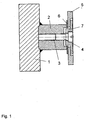
- FIG. 1 is a side sectional view of a conventionally mounted on a mold rib core enclosure plate, in particular at first assembly, indicated by Kernum chargedsschraube and locking plate. Accordingly, on the wall of a reactor pressure vessel core scaffold 1 - for simplification only partially shown here - Form ribs 2, each with a threaded bore 3 for receiving a Kernum chargedsschraube 4 for fixing a corresponding Kernum chargedsbleches 5 are provided.
- the locking plate 7 has an internal countersink with hole, in particular bore, for the penetration of the core surround screw 4 and engages in the installed state in a recess of Kernum chargedsbleches 5, whereby this is fixed after installation of the Kernum conductedsschraube 4 in its original position and orientation.
- the Kernum forcedsschraube 4 is thereby torque controlled screwed into the threaded hole 3 of the respective rib 2, wherein it passes through the locking plate 7, the Kernum chargedsblech 5 and the spacer 6 and this attached to the rib 2.
- the screw After screwing the Kernum chargedsschraube 4, the screw is usually secured by welding with the locking plate 7 against rotation and / or loosening.
- the surfaces of screw 4 and locking plate 7 are then flush ground to remove by the welding process supernatants and / or seams and to create a smooth, flat top or inner surface.
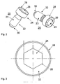
- an exemplary trained core surround screw 20 is shown in a spatial representation from two different viewing directions.
- the aforementioned screw 20 in this case comprises a screw shaft 22 with external thread 23 and a screw head 24 with screw head profile, preferably external hexagon 26, which has an at least partially encircling, collar-like Anformung 28, hereinafter also referred to as a screw head collar has.
- the Anformung example also annular and / or be formed as a disc.
- the taper 30 can also be formed pyramidal or with any other geometric base.
- a running free area 32 for engagement of a corresponding tool such as the nut of a torque wrench or a ring wrench, for torque-controlled installation of the core wrap screw 20 is provided.
- the free area 32 is formed like a groove.
- the screw head collar 28 is, in particular with regard to its material thickness, designed such that it is mechanically deformed relatively easily by the action of force and / or has a wall thickness or material thickness of about 0.5 mm.
- the aforementioned SSenkopfanformung in particular designed as a screw head collar 28 Anformung can be formed integrally or from individual segments. Furthermore, it can surround the screw head 24 with a profile, in particular the external hexagon 26 of the core surrounding screw 20, completely or, for example, if formed from individual segments, only partially, in particular in sections, circumferentially.
- FIG. 4 a side sectional view of an exemplary formed Kernum forcedsschraube 20 with screw head collar 28 is shown.
- free shaft end 30 is tapered designed as a truncated cone to facilitate later attachment and / or screwing the Kernum chargedsschraube 20.
- tapered free shaft end 30 for example, pyramidal with square, triangular or polygonal, in particular hexagonal or octagonal base surface, possible.
- the shank 22 proportionately has an external thread 23, in particular an M12 thread, through which the screw 20 can be screwed and fixed in a complementary threaded bore of a shaped rib.
- a torque wrench with appropriate nut can be used.
- a screw head collar 28 is formed, which surrounds the head profile 26 circumferentially. Between screw head collar 28 and head profile 26, in particular an external hexagon, a distance is formed, so that a groove-shaped circumferentially encircling open area 32 is created, which allows the engagement of a corresponding tool for torque-controlled screwing the screw 20.
- the screw head collar 28 can also be formed from a plurality of individual segments, wherein the segments can surround the screw head 24 circumferentially only partially.
- the individual segments may be arranged circumferentially spaced from each other.
- the screw head collar 28 is designed such that it is flush with the head profile 26, that is, the collar height corresponds to the profile and / or head height.
- the screw head collar 28 may also have a smaller height than the screw head 24 or its profile 26, so that the screw head 24 protrudes or the profile 26 projects beyond the collar 28.
- the trained as a collar sterenkopfanformung 28 has a material thickness of in particular 0.5 mm.
- the transition region 36 between the shaft 22 and the head 24 of the screw is rotationally symmetrical and has, as in Fig. 4 shown, a curved, in particular a nearly parabolic course on.
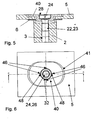
- FIG. 5 is a side sectional view of a to a rib 2, by means of an arrangement for the secure installation and / or replacement of Kernum chargedsschrauben with at least one Kernum chargedsschraube 20 with synchronenkopfanformung 28 and a locking plate 40 mounted Kernum chargedsbleches 5 shown.
- a spacer 6 is provided between the form of rib 2 and core surround plate 5.
- the inserted Kernum chargedsschraube 20 according to FIG. 2 or FIG. 4 comprises a shaft 22 with external thread 23 and a screw head 24 with at least one, the screw head 24 at least partially circumferentially surrounding Anformung 28, which is formed like a collar in the example shown here.
- the locking plate 40 has, as well as in Fig. 7 indicated, an oval approximately elliptical basic shape, which rests in the installed state almost positively and accurately fit in a corresponding recess 41 of the Kernum chargedsbleches 5, whereby it is mechanically secured against rotation.
- the locking plate 40 and in particular its inner countersink 42 has four mutually offset by 90 ° recess 46 for engagement 48 of the collar-like designed sterenkopfanformung 28 for mechanical securing of the Kernum chargedsschraube 20th
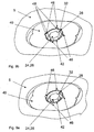
- Fig. 6 is a plan view of the according to Fig. 5 mounted Kernum chargedsblech 5, wherein the locking plate 40 rests in the complementary recess 41 of the respective Kernum chargedsbleches 5. Furthermore, in the region of the inner countersink 42 of the securing plate 40, the screw head 24 or its external hexagonal profile 26 of the built-in core surrounding screw 20 with screw head collar 28 and the groove profile 32 formed between profile 26 and collar 28 are indicated, wherein the collar 28 has four deformations 48 which are in the four recesses 46 of the locking plate 40 engage.
- the ringenkopfanformung may also be formed like a ring or disc, wherein the associated locking plate, the at least one recess for engaging the ringenkopfanformung 28 is then preferably arranged in the bottom region of the trough-like inner recess 42 of the locking plate 40.
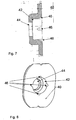
- Fig. 7 is a side sectional view of a lock plate 40 with trough-like ausgestalteter inner countersink 42 for receiving the screw head 24 and hole or bore 44 for the penetration of the core surround screw 20 by the locking plate 40 and the Kernum chargedsblech 5 indicated in the complementary threaded bore of a shaped rib 2.
- the locking plate 40 and in particular its inner countersink 42 has four mutually offset by 90 ° recesses 46 for engaging the collar-like designed SSenkopfanformung 28 for mechanical securing of the Kernum shockedsschraube 20th
- any number of recesses 46 for engagement of the screw head collar 28 after deformation can be realized, for example, 1,2,3,6,8 etc.
- Fig. 8 is a perspective perspective view of a locking plate 40 according to the FIGS. 6 and 7 shown.
- the locking plate 40 has in a circular, trough-shaped inner countersink 42, in the bottom of a first recess 44, in particular a hole or hole, is provided for the penetration of the core screw 2 in the complementary threaded bore 3 of the molding ribs for fastening the respective Kernum chargedsbleches 5.
- the recess 44 in particular a bore, the inner countersink 42 for the passage of the core surround screw 20 is preferably arranged centrally or centrally in the bottom of the countersink.
- the locking plate 40 in particular in the upper edge region of the trough-shaped inner countersink 42, four bevels formed as chamfers further recesses 46 are provided, in which the Anformung 28 of the screw head 24 engages against mechanical deformation to secure the Kernum chargedsschraube 20 against rotation.
- the recesses 46 are offset by 90 ° to each other, but can also be arranged offset from each other at any other angle.
- the countersink 42 is designed in such a way that it completely accommodates the screw head 24 with molding 28 of the core surround screw 20 and that the screw head 24 terminates flush with the upper side of the lock plate 40, as well as in FIGS FIGS. 9a and 9b specified.
- FIG. 9a and Figure 9b is in each case a spatial representations of resting in Kernum chargedsblech 20 locking plate 40 according to Fig. 6 shown, wherein here the locking plate 40 rests in the complementary recess 41 of the respective Kernum chargedsbleches 5. Furthermore, in the region of the internal countersinking 42 of the securing plate 40, the screw head 24 or its external hexagonal profile 26 of the built-in core surrounding screw 20 with screw head collar 28 as well as the free-space 32 formed between profile 26 and collar 28 are indicated Fig. 9b the collar 28 has four deformations 48 which engage in the four recesses 46 of the locking plate 40.
- FIG. 2 shows a side sectional view of a core surround plate 5 mounted on a shaped rib 2, by means of an arrangement for the secure installation and / or replacement of core surround screws 4, 20 with at least one core surround screw 20 with screw head molding 28 and a lock plate 40, by way of example after replacement of a core surround screw 4 ,
- Fig. 5 Known arrangement is also a sectional view of a Kernum chargedsschraube 20 according to the invention with clearly recognizable ringenkopfanformung 28 and free area 32 between the screw head 24 and Anformung 28 indicated.
- FIG. 10 at least two recesses, in particular holes 50 indicated, which extend through the inserted spacer 6 and the respective Kernum chargedsblech 5 into the respective form of rib 2, wherein in at least two of the recesses, in particular bores 50, depending on a locking pin 52 is inserted.
- the purpose of the locking pins 52 is to hold the respective core enclosing plate 5 and the installed spacer 6 in position after unscrewing the core surrounding screw 4, 20.
- Bore depth and locking pin length are matched to one another such that each inserted locking pin 52 terminates with the respective Kernum chargedsblech 5 or ends before this.
- the pin 52 is in particular shorter than the bore 50 is formed.
- FIG. 10 Due to the matching features, the further explanation of the FIG. 10 is based on the descriptions of FIG. 5 such as FIG. 4 directed.
- the post-processing of the seat of the locking plate can be carried out as needed.
Landscapes
- Engineering & Computer Science (AREA)
- General Engineering & Computer Science (AREA)
- Mechanical Engineering (AREA)
- Connection Of Plates (AREA)
Claims (28)
- Ensemble de montage sûr et/ou de remplacement de vis (4, 20) d'enceinte de coeur en vue du montage de tôles (5) d'enceinte de coeur, l'ensemble présentant au moins une vis (20) d'enceinte de coeur ainsi qu'au moins une plaque de blocage (40),
caractérisé en ce que
la vis (20) d'enceinte de coeur présente une tête de vis dotée d'au moins une moulure (28) qui entoure au moins une partie de la périphérie de la tête de vis (24) et en ce qu'au moins une dépression intérieure (42) destinée à reprendre la tête (24) de la vis qui présente une première découpe (44) destinée à être traversée par la vis (20) d'enceinte de coeur ainsi qu'au moins une autre découpe (46) destinée à être engagée par la moulure (28) de la tête de vis pour empêcher mécaniquement la vis (20) d'enceinte de coeur de tourner sont prévues dans la plaque de blocage (40). - Ensemble selon la revendication 1, caractérisé en ce que la tête (24) de la vis présente un profil (24).
- Ensemble selon l'une des revendications 1 ou 2, caractérisé en ce que la moulure (28) de la vis (20) d'enceinte de coeur a la forme d'un anneau ou d'un collet de tête de vis.
- Ensemble selon la revendication 3, caractérisé en ce qu'une partie libre (32), en particulier en forme de rainure, est formée pour permettre l'engagement d'un outil qui permet de monter la vis (20) d'enceinte de coeur en contrôlant le couple de rotation, est prévue sur la vis (20) d'enceinte de coeur entre la moulure (28) configurée comme collet de tête de vis et la tête (24) de la vis.
- Ensemble selon l'une des revendications 1 à 4 qui précèdent, caractérisé en ce que la moulure (28) de la vis (20) d'enceinte de coeur est mécaniquement déformable et/ou présente une épaisseur de matière de 0,5 mm.
- Ensemble selon l'une des revendications 1 à 5 qui précèdent, caractérisé en ce que la moulure (28) de la vis (20) d'enceinte de coeur, en particulier la moulure configurée comme collet de tête de vis, est formée d'un seul tenant ou en plusieurs segments distincts.
- Ensemble selon la revendication 6, caractérisé en ce que les segments sont disposés à distance les uns des autres à la périphérie de la vis (20) d'enceinte de coeur.
- Ensemble selon l'une des revendications 3 à 7 qui précèdent, caractérisé en ce que la moulure (28) de la vis (20) d'enceinte de coeur configurée comme collet de tête de vis se raccorde à chant avec le bord supérieur ou le côté supérieur de la tête (24) de la vis ou présente une hauteur de collet plus petite que la tête (24) de la vis et en particulier de la tête (24) de la vis configurée comme vis à six pans extérieurs.
- Ensemble selon l'une des revendications 1 à 8 qui précèdent, caractérisé en ce que la partie de transition (36) entre la tige (22) et la tête (24) de la vis (20) d'enceinte de coeur présente une courbure en particulier de forme parabolique.
- Ensemble selon l'une des revendications 1 à 9 qui précèdent, caractérisé en ce que la tige (22) de la vis (20) d'enceinte de coeur présente une extrémité (30) libre qui se rétrécit, en particulier coniquement.
- Ensemble selon les revendications 1 à 10, caractérisé en ce que la vis (20) d'enceinte de coeur est montée en contrôlant le couple de rotation et en ce que la moulure (28) de la tête (24) de la vis peut être déformée mécaniquement de telle sorte que la moulure (28) s'engage dans la ou les autres découpes (46) de la plaque de blocage (40), la vis (20) étant ainsi protégée mécaniquement d'une rotation et/ou d'un desserrage.
- Ensemble selon l'une des revendications 1 à 11, caractérisé en ce que la plaque de blocage (40) présente dans sa dépression intérieure (42) une première découpe (44), en particulier un trou (44), disposée de préférence au centre ou au milieu, et/ou un alésage qui permettent à la vis (20) d'enceinte de coeur de s'engager dans un filet intérieur (3) complémentaire d'une nervure moulée (2) destinée à fixer la tôle (5) d'enceinte de coeur.
- Ensemble selon l'une des revendications 1 à 12, caractérisé en ce que la ou les autres découpes (46) sont disposées dans la bordure et/ou la paroi supérieure de la dépression intérieure (42) de la plaque de blocage (40).
- Ensemble selon l'une des revendications 1 à 12, caractérisé en ce que la ou les autres découpes (46) sont disposées au niveau du fond de la dépression intérieure (42) de la plaque de blocage (40).
- Ensemble selon l'une des revendications 1 à 14, caractérisé en ce que la plaque de blocage (40) présente quatre autres découpes décalées mutuellement de 90° pour permettre l'engagement de la moulure (28) de la tête de la vis, en particulier de la moulure configurée comme collet de la tête de la vis, et pour bloquer mécaniquement la vis (20) d'enceinte de coeur.
- Ensemble selon l'une des revendications 1 à 15, caractérisé en ce que la dépression intérieure (42) est configurée de manière à reprendre complètement la tête (24) dotée d'une moulure (28) de la vis (20) d'enceinte de coeur et/ou en ce qu'en position montée, la tête de la vis se raccorde à chant avec le côté supérieur de la plaque de blocage (40).
- Ensemble selon l'une des revendications 1 à 16, caractérisé en ce que la plaque de blocage (40) présente une forme de base ovale et en particulier elliptique et/ou, lorsque la vis (20) d'enceinte de coeur est montée, repose dans une découpe (41) de forme appropriée de la tôle (5) d'enceinte de coeur, de sorte que la plaque de blocage (40) est empêchée de tourner par rapport à la tôle (5) d'enceinte de coeur lorsque la vis (20) d'enceinte de coeur est serrée.
- Ensemble selon l'une des revendications 1 à 17, caractérisé en ce que la dépression intérieure (42) a une forme circulaire dont le diamètre intérieur et la profondeur sont adaptés à ceux de la tête (24) de la vis dotée d'une moulure (28).
- Ensemble selon l'une des revendications 1 à 18 qui précèdent, caractérisé en ce que la dépression intérieure (42) de la plaque de blocage (40) présente quatre découpes (46) décalées de 90° et qui engagent la moulure de la tête de la vis.
- Ensemble selon l'une des revendications 12 à 19 qui précèdent, caractérisé en ce qu'il présente au moins deux découpes et/ou alésages (50) qui s'étendent et/ou s'engagent dans la plaque de blocage (40) et/ou dans au moins un disque d'écartement (6) et/ou dans la tôle (5) d'enceinte de coeur jusque dans une nervure moulée (2).
- Ensemble selon la revendication 20, caractérisé en ce qu'une tige de blocage (52) est insérée dans au moins deux des découpes (50).
- Ensemble selon la revendication 21, caractérisé en ce que la profondeur de la découpe (44) ou de l'alésage et la longueur des tiges de blocage sont accordées mutuellement de telle sorte que lorsque la tige de blocage (52) est insérée, elle se raccorde à chant avec la tôle (5) d'enceinte de coeur mais au moins n'en déborde pas.
- Procédé de montage et/ou de remplacement de vis d'enceinte de coeur servant à fixer de manière sûre des tôles d'enceinte de coeur au moyen d'un ensemble selon l'une des revendications 1 à 22, dans lequel, successivement :- la tête (24) d'une vis (4) d'enceinte de coeur existante et à remplacer est libérée,- un profil approprié, en particulier à quatre pans, est formé pour dévisser la vis (4) existante,- la vis (4) existante est dévissée et la plaque de blocage (7) existante est enlevée,- une nouvelle plaque de blocage (40) présentant une dépression intérieure (42) et au moins une découpe (46) de blocage mécanique de la vis (20) d'enceinte de coeur est placée,- une vis (20) d'enceinte de coeur dotée d'une moulure (28) est vissée sur la tête de la vis et- la moulure (28) est déformée mécaniquement par l'application d'une force de manière à s'engager au moins partiellement dans la ou les découpes (46) de la dépression intérieure (42) de la plaque de blocage (40), de telle sorte que la nouvelle vis (20) d'enceinte de coeur soit empêchée mécaniquement de tourner et/ou de se dévisser.
- Procédé selon la revendication 23, caractérisé en ce qu'avant de placer la plaque de blocage (40), la surface d'assise de la plaque de blocage (40) reçoit un usinage de finition.
- Procédé selon l'une des revendications 23 à 24, caractérisé en ce qu'avant la finition de la surface d'assise de la plaque de blocage (40), un mandrin de guidage est installé avant d'être de nouveau enlevé après la finition de la surface d'assise.
- Procédé selon l'une des revendications 23 à 25, caractérisé en ce qu'avant le desserrage de la vis (20), au moins deux découpes et/ou alésages (50) sont ménagés à travers la plaque de blocage (40) et/ou au moins à travers un disque d'écartement (6) et/ou la tôle (5) d'enceinte de coeur jusque dans une nervure moulée (2).
- Procédé selon la revendication 26, caractérisé en ce qu'une tige de blocage (52) est insérée dans au moins deux des découpes (50) alésées.
- Procédé selon la revendication 27, caractérisé en ce que la profondeur de l'alésage et la longueur de la tige de blocage sont accordées mutuellement de telle sorte que la tige de blocage (52) insérée se raccorde à chant avec la tôle (5) d'enceinte de coeur mais au moins n'en déborde pas.
Applications Claiming Priority (1)
| Application Number | Priority Date | Filing Date | Title |
|---|---|---|---|
| DE102006040272A DE102006040272A1 (de) | 2006-08-28 | 2006-08-28 | Kernumfassungsschraube, Anordnung und Verfahren zum gesicherten Einbau und/oder Austausch von Kernumfassungsschrauben |
Publications (2)
| Publication Number | Publication Date |
|---|---|
| EP1892428A1 EP1892428A1 (fr) | 2008-02-27 |
| EP1892428B1 true EP1892428B1 (fr) | 2012-02-08 |
Family
ID=38688120
Family Applications (1)
| Application Number | Title | Priority Date | Filing Date |
|---|---|---|---|
| EP07016525A Active EP1892428B1 (fr) | 2006-08-28 | 2007-08-23 | Vis d'enroulement de noyau, agencement et procédé d'installation et/ou d'échange sécurisé de vis d'enroulement de noyau |
Country Status (5)
| Country | Link |
|---|---|
| EP (1) | EP1892428B1 (fr) |
| AT (1) | ATE544956T1 (fr) |
| DE (1) | DE102006040272A1 (fr) |
| RU (1) | RU2460906C2 (fr) |
| UA (1) | UA97230C2 (fr) |
Families Citing this family (3)
| Publication number | Priority date | Publication date | Assignee | Title |
|---|---|---|---|---|
| GB2485949A (en) * | 2009-09-25 | 2012-05-30 | Mclaren Performance Technologies Inc | Staked nut and flange for gear support |
| CN109901349A (zh) * | 2017-12-11 | 2019-06-18 | 深圳光峰科技股份有限公司 | 镜头调整固定结构及投影设备 |
| CN113048131A (zh) * | 2019-12-27 | 2021-06-29 | 上海申标标准件有限公司 | 一种多用途螺栓 |
Family Cites Families (18)
| Publication number | Priority date | Publication date | Assignee | Title |
|---|---|---|---|---|
| FR493783A (fr) * | 1918-12-12 | 1919-08-21 | Antoine Durand | Frein d'écrou |
| DE2042312A1 (de) * | 1970-05-22 | 1971-12-02 | Bbc Brown Boveri & Cie | Sicherung für Innen-Sechskantschrauben |
| DE2151932A1 (de) * | 1971-10-19 | 1973-04-26 | Zahnradfabrik Friedrichshafen | Schraubensicherung |
| DE7603185U1 (de) * | 1976-02-05 | 1976-06-03 | Dynamit Nobel Ag, 5210 Troisdorf | Befestigungsscheibe zum fixieren von lose verlegten dichtungsbahnen |
| DE2747994A1 (de) * | 1977-10-26 | 1979-05-03 | Kraftwerk Union Ag | Verdrehsicherung fuer zylinderkopfschrauben mit innenmehrkant und werkzeug zum plastischen verformen fuer eine solche verdrehsicherung |
| DE2903706A1 (de) * | 1979-01-31 | 1980-08-14 | Kraftwerk Union Ag | Verdrehsicherung fuer in ein bauteil eingeschraubte kopfschrauben |
| SU812998A1 (ru) * | 1979-04-09 | 1981-03-15 | Запорожский Проектно-Конструкторскийи Технологический Институт | Стопорное устройство |
| DE3626338A1 (de) * | 1986-08-02 | 1988-02-11 | Bbc Reaktor Gmbh | Sicherung fuer eine in einem werkstueck versenkte zylinderkopfschraube |
| DE8620893U1 (de) * | 1986-08-02 | 1986-11-27 | Abb Reaktor Gmbh, 68167 Mannheim | Sicherung für eine in einem Werkstück versenkte Zylinderkopfschraube |
| YU153787A (en) * | 1986-10-31 | 1990-04-30 | Siemens Ag | Mechanical connective element, protected against releasing |
| DE8710905U1 (de) * | 1987-08-10 | 1988-01-28 | Siemens AG, 1000 Berlin und 8000 München | Sicherbare Behälterschraube |
| DE9004238U1 (de) * | 1990-04-11 | 1991-08-08 | Waldemar Link GmbH & Co, 22339 Hamburg | Schraubkopf mit Sicherungseinrichtung |
| DE9013075U1 (de) * | 1990-09-14 | 1990-11-15 | ABB Reaktor GmbH, 6800 Mannheim | Sicherung für eine in einer Senkbohrung eines Bauteiles angeordneten Kopfschraube |
| DE9013077U1 (de) * | 1990-09-14 | 1990-11-15 | ABB Reaktor GmbH, 6800 Mannheim | Sicherung für eine in einer Senkbohrung eines Bauteiles angeordneten Kopfschraube |
| DE4038507C1 (en) * | 1990-12-03 | 1992-06-17 | Abb Reaktor Gmbh, 6800 Mannheim, De | Device for remotely seating and tightening screw - includes ultrasound test head for measuring longitudinal expansion of screw shaft, used in nuclear reactor installation |
| DE19540743A1 (de) * | 1995-11-02 | 1997-05-07 | Asea Brown Boveri | Schraubensicherung |
| US6164886A (en) * | 1999-06-01 | 2000-12-26 | Westinghouse Electric Company Llc | Bolt with integral locking member |
| US6669419B1 (en) * | 2002-01-25 | 2003-12-30 | Radio Systems Corporation | Probe locking washer |
-
2006
- 2006-08-28 DE DE102006040272A patent/DE102006040272A1/de not_active Withdrawn
-
2007
- 2007-08-23 EP EP07016525A patent/EP1892428B1/fr active Active
- 2007-08-23 AT AT07016525T patent/ATE544956T1/de active
- 2007-08-27 UA UAA200709679A patent/UA97230C2/ru unknown
- 2007-08-27 RU RU2007132229/12A patent/RU2460906C2/ru active
Also Published As
| Publication number | Publication date |
|---|---|
| UA97230C2 (ru) | 2012-01-25 |
| EP1892428A1 (fr) | 2008-02-27 |
| ATE544956T1 (de) | 2012-02-15 |
| RU2460906C2 (ru) | 2012-09-10 |
| RU2007132229A (ru) | 2009-03-10 |
| DE102006040272A1 (de) | 2008-03-06 |
Similar Documents
| Publication | Publication Date | Title |
|---|---|---|
| EP2788617B1 (fr) | Pale de rotor et dispositif d'assemblage | |
| DE69630901T2 (de) | Verfahren zum einpressen eines verbindungselementes, bolzen, nietmatrize und komponentenanordnung | |
| DE4033763C2 (de) | Vorrichtung zum Sichern einer in einer Öffnung in einer Verkleidung aufgenommenen Mutter | |
| EP1165283B1 (fr) | Systeme de support fonctionnel | |
| DE102011054861A1 (de) | Befestigungselement mit Toleranzausgleichsfunktion | |
| DE102011052610A1 (de) | Windturbinenankerelement | |
| DE102007018025A1 (de) | Windenergieanlagenturm | |
| EP2154367B1 (fr) | Procédé de montage d'un moyeu d'hélice sur un arbre de rotor d'une éolienne et éolienne | |
| EP2140968B2 (fr) | Dispositif destinés à la compression d'éléments de fixation | |
| CH631789A5 (de) | Verdrehsicherung fuer zylinderkopfschrauben mit innenmehrkant und werkzeug zum plastischen verformen fuer eine solche verdrehsicherung. | |
| EP1892428B1 (fr) | Vis d'enroulement de noyau, agencement et procédé d'installation et/ou d'échange sécurisé de vis d'enroulement de noyau | |
| EP1003243A2 (fr) | Procédé de fabrication d'une connexion électrique à une partie en tôle et ensemble de montage | |
| DE202020103617U1 (de) | Verdrehsicherung | |
| EP2627915A1 (fr) | Dispositif d'ancrage destiné à fixer une pièce sur un élément de support | |
| EP3974602B1 (fr) | Dispositif d'accouplement permettant d'accoupler des segments d'une tour d'une éolienne et procédé de montage pour cela | |
| DE102017103768A1 (de) | Befestigungsvorrichtung und Befestigungsbaugruppe | |
| EP3816369B1 (fr) | Dispositif d'ancrage, ancrage pourvu de dispositif d'ancrage et procédé de fabrication d'ancrage | |
| EP3439784B1 (fr) | Système d'assemblage servant à l'assemblage d'éléments de carter d'un broyeur | |
| EP3988803B1 (fr) | Unité fonctionnelle pourvue d'élément de connexion et d'élément de fixation | |
| DE102014016713B4 (de) | Elektrisches Anschlussteil und Verfahren zum Herstellen eines solchen Anschlussteils | |
| EP2141369A1 (fr) | Elément de fixation | |
| DE102019110635A1 (de) | Zusammenbauteil bestehend aus einem Bauteil und einem Element mit einem Kopfteil und einem auf einer Seite des Kopfteils angeordneten Kragen sowie Herstellungsverfahren | |
| DE102019109904A1 (de) | Turmsegment und Verfahren zum Aufbau eines Turms | |
| EP3564545A1 (fr) | Composant d'assemblage comprenant un composant et d'un élément doté d'une partie de tête et d'un col disposé sur un côté de la partie de tête ainsi que son procédé de fabrication | |
| DE102011001919A1 (de) | Ankeranordnung, Verfahren zu deren Montage und Verfahren zur Herstellung eines Fundaments mit einer Ankeranordnung |
Legal Events
| Date | Code | Title | Description |
|---|---|---|---|
| PUAI | Public reference made under article 153(3) epc to a published international application that has entered the european phase |
Free format text: ORIGINAL CODE: 0009012 |
|
| AK | Designated contracting states |
Kind code of ref document: A1 Designated state(s): AT BE BG CH CY CZ DE DK EE ES FI FR GB GR HU IE IS IT LI LT LU LV MC MT NL PL PT RO SE SI SK TR |
|
| AX | Request for extension of the european patent |
Extension state: AL BA HR MK YU |
|
| 17P | Request for examination filed |
Effective date: 20080222 |
|
| 17Q | First examination report despatched |
Effective date: 20080407 |
|
| R17C | First examination report despatched (corrected) |
Effective date: 20080905 |
|
| AKX | Designation fees paid |
Designated state(s): AT BE BG CH CY CZ DE DK EE ES FI FR GB GR HU IE IS IT LI LT LU LV MC MT NL PL PT RO SE SI SK TR |
|
| GRAP | Despatch of communication of intention to grant a patent |
Free format text: ORIGINAL CODE: EPIDOSNIGR1 |
|
| GRAS | Grant fee paid |
Free format text: ORIGINAL CODE: EPIDOSNIGR3 |
|
| GRAA | (expected) grant |
Free format text: ORIGINAL CODE: 0009210 |
|
| AK | Designated contracting states |
Kind code of ref document: B1 Designated state(s): AT BE BG CH CY CZ DE DK EE ES FI FR GB GR HU IE IS IT LI LT LU LV MC MT NL PL PT RO SE SI SK TR |
|
| REG | Reference to a national code |
Ref country code: GB Ref legal event code: FG4D Free format text: NOT ENGLISH |
|
| REG | Reference to a national code |
Ref country code: CH Ref legal event code: EP Ref country code: AT Ref legal event code: REF Ref document number: 544956 Country of ref document: AT Kind code of ref document: T Effective date: 20120215 |
|
| REG | Reference to a national code |
Ref country code: DE Ref legal event code: R096 Ref document number: 502007009234 Country of ref document: DE Effective date: 20120405 |
|
| REG | Reference to a national code |
Ref country code: NL Ref legal event code: VDEP Effective date: 20120208 |
|
| LTIE | Lt: invalidation of european patent or patent extension |
Effective date: 20120208 |
|
| PG25 | Lapsed in a contracting state [announced via postgrant information from national office to epo] |
Ref country code: IS Free format text: LAPSE BECAUSE OF FAILURE TO SUBMIT A TRANSLATION OF THE DESCRIPTION OR TO PAY THE FEE WITHIN THE PRESCRIBED TIME-LIMIT Effective date: 20120608 Ref country code: LT Free format text: LAPSE BECAUSE OF FAILURE TO SUBMIT A TRANSLATION OF THE DESCRIPTION OR TO PAY THE FEE WITHIN THE PRESCRIBED TIME-LIMIT Effective date: 20120208 Ref country code: NL Free format text: LAPSE BECAUSE OF FAILURE TO SUBMIT A TRANSLATION OF THE DESCRIPTION OR TO PAY THE FEE WITHIN THE PRESCRIBED TIME-LIMIT Effective date: 20120208 |
|
| REG | Reference to a national code |
Ref country code: SK Ref legal event code: T3 Ref document number: E 11782 Country of ref document: SK |
|
| REG | Reference to a national code |
Ref country code: IE Ref legal event code: FD4D |
|
| PG25 | Lapsed in a contracting state [announced via postgrant information from national office to epo] |
Ref country code: PT Free format text: LAPSE BECAUSE OF FAILURE TO SUBMIT A TRANSLATION OF THE DESCRIPTION OR TO PAY THE FEE WITHIN THE PRESCRIBED TIME-LIMIT Effective date: 20120608 Ref country code: PL Free format text: LAPSE BECAUSE OF FAILURE TO SUBMIT A TRANSLATION OF THE DESCRIPTION OR TO PAY THE FEE WITHIN THE PRESCRIBED TIME-LIMIT Effective date: 20120208 Ref country code: GR Free format text: LAPSE BECAUSE OF FAILURE TO SUBMIT A TRANSLATION OF THE DESCRIPTION OR TO PAY THE FEE WITHIN THE PRESCRIBED TIME-LIMIT Effective date: 20120509 Ref country code: LV Free format text: LAPSE BECAUSE OF FAILURE TO SUBMIT A TRANSLATION OF THE DESCRIPTION OR TO PAY THE FEE WITHIN THE PRESCRIBED TIME-LIMIT Effective date: 20120208 |
|
| PG25 | Lapsed in a contracting state [announced via postgrant information from national office to epo] |
Ref country code: CY Free format text: LAPSE BECAUSE OF FAILURE TO SUBMIT A TRANSLATION OF THE DESCRIPTION OR TO PAY THE FEE WITHIN THE PRESCRIBED TIME-LIMIT Effective date: 20120208 |
|
| PG25 | Lapsed in a contracting state [announced via postgrant information from national office to epo] |
Ref country code: CZ Free format text: LAPSE BECAUSE OF FAILURE TO SUBMIT A TRANSLATION OF THE DESCRIPTION OR TO PAY THE FEE WITHIN THE PRESCRIBED TIME-LIMIT Effective date: 20120208 Ref country code: IE Free format text: LAPSE BECAUSE OF FAILURE TO SUBMIT A TRANSLATION OF THE DESCRIPTION OR TO PAY THE FEE WITHIN THE PRESCRIBED TIME-LIMIT Effective date: 20120208 Ref country code: DK Free format text: LAPSE BECAUSE OF FAILURE TO SUBMIT A TRANSLATION OF THE DESCRIPTION OR TO PAY THE FEE WITHIN THE PRESCRIBED TIME-LIMIT Effective date: 20120208 Ref country code: SE Free format text: LAPSE BECAUSE OF FAILURE TO SUBMIT A TRANSLATION OF THE DESCRIPTION OR TO PAY THE FEE WITHIN THE PRESCRIBED TIME-LIMIT Effective date: 20120208 Ref country code: RO Free format text: LAPSE BECAUSE OF FAILURE TO SUBMIT A TRANSLATION OF THE DESCRIPTION OR TO PAY THE FEE WITHIN THE PRESCRIBED TIME-LIMIT Effective date: 20120208 Ref country code: EE Free format text: LAPSE BECAUSE OF FAILURE TO SUBMIT A TRANSLATION OF THE DESCRIPTION OR TO PAY THE FEE WITHIN THE PRESCRIBED TIME-LIMIT Effective date: 20120208 Ref country code: SI Free format text: LAPSE BECAUSE OF FAILURE TO SUBMIT A TRANSLATION OF THE DESCRIPTION OR TO PAY THE FEE WITHIN THE PRESCRIBED TIME-LIMIT Effective date: 20120208 |
|
| PG25 | Lapsed in a contracting state [announced via postgrant information from national office to epo] |
Ref country code: IT Free format text: LAPSE BECAUSE OF FAILURE TO SUBMIT A TRANSLATION OF THE DESCRIPTION OR TO PAY THE FEE WITHIN THE PRESCRIBED TIME-LIMIT Effective date: 20120208 |
|
| PLBE | No opposition filed within time limit |
Free format text: ORIGINAL CODE: 0009261 |
|
| STAA | Information on the status of an ep patent application or granted ep patent |
Free format text: STATUS: NO OPPOSITION FILED WITHIN TIME LIMIT |
|
| 26N | No opposition filed |
Effective date: 20121109 |
|
| BERE | Be: lapsed |
Owner name: WESTINGHOUSE ELECTRIC GERMANY G.M.B.H. Effective date: 20120831 |
|
| REG | Reference to a national code |
Ref country code: DE Ref legal event code: R097 Ref document number: 502007009234 Country of ref document: DE Effective date: 20121109 |
|
| REG | Reference to a national code |
Ref country code: CH Ref legal event code: PL |
|
| PG25 | Lapsed in a contracting state [announced via postgrant information from national office to epo] |
Ref country code: MC Free format text: LAPSE BECAUSE OF NON-PAYMENT OF DUE FEES Effective date: 20120831 |
|
| GBPC | Gb: european patent ceased through non-payment of renewal fee |
Effective date: 20120823 |
|
| PG25 | Lapsed in a contracting state [announced via postgrant information from national office to epo] |
Ref country code: CH Free format text: LAPSE BECAUSE OF NON-PAYMENT OF DUE FEES Effective date: 20120831 Ref country code: ES Free format text: LAPSE BECAUSE OF FAILURE TO SUBMIT A TRANSLATION OF THE DESCRIPTION OR TO PAY THE FEE WITHIN THE PRESCRIBED TIME-LIMIT Effective date: 20120519 Ref country code: LI Free format text: LAPSE BECAUSE OF NON-PAYMENT OF DUE FEES Effective date: 20120831 |
|
| REG | Reference to a national code |
Ref country code: FR Ref legal event code: ST Effective date: 20130430 |
|
| PG25 | Lapsed in a contracting state [announced via postgrant information from national office to epo] |
Ref country code: BE Free format text: LAPSE BECAUSE OF NON-PAYMENT OF DUE FEES Effective date: 20120831 |
|
| REG | Reference to a national code |
Ref country code: HU Ref legal event code: AG4A Ref document number: E015747 Country of ref document: HU |
|
| PG25 | Lapsed in a contracting state [announced via postgrant information from national office to epo] |
Ref country code: GB Free format text: LAPSE BECAUSE OF NON-PAYMENT OF DUE FEES Effective date: 20120823 Ref country code: BG Free format text: LAPSE BECAUSE OF FAILURE TO SUBMIT A TRANSLATION OF THE DESCRIPTION OR TO PAY THE FEE WITHIN THE PRESCRIBED TIME-LIMIT Effective date: 20120508 |
|
| PG25 | Lapsed in a contracting state [announced via postgrant information from national office to epo] |
Ref country code: FR Free format text: LAPSE BECAUSE OF NON-PAYMENT OF DUE FEES Effective date: 20120831 |
|
| REG | Reference to a national code |
Ref country code: AT Ref legal event code: MM01 Ref document number: 544956 Country of ref document: AT Kind code of ref document: T Effective date: 20120831 |
|
| PG25 | Lapsed in a contracting state [announced via postgrant information from national office to epo] |
Ref country code: AT Free format text: LAPSE BECAUSE OF NON-PAYMENT OF DUE FEES Effective date: 20120831 |
|
| PG25 | Lapsed in a contracting state [announced via postgrant information from national office to epo] |
Ref country code: MT Free format text: LAPSE BECAUSE OF FAILURE TO SUBMIT A TRANSLATION OF THE DESCRIPTION OR TO PAY THE FEE WITHIN THE PRESCRIBED TIME-LIMIT Effective date: 20120208 |
|
| PG25 | Lapsed in a contracting state [announced via postgrant information from national office to epo] |
Ref country code: TR Free format text: LAPSE BECAUSE OF FAILURE TO SUBMIT A TRANSLATION OF THE DESCRIPTION OR TO PAY THE FEE WITHIN THE PRESCRIBED TIME-LIMIT Effective date: 20120208 |
|
| PG25 | Lapsed in a contracting state [announced via postgrant information from national office to epo] |
Ref country code: LU Free format text: LAPSE BECAUSE OF NON-PAYMENT OF DUE FEES Effective date: 20120823 |
|
| PGFP | Annual fee paid to national office [announced via postgrant information from national office to epo] |
Ref country code: HU Payment date: 20251028 Year of fee payment: 19 |
|
| PGFP | Annual fee paid to national office [announced via postgrant information from national office to epo] |
Ref country code: DE Payment date: 20251010 Year of fee payment: 19 |
|
| PGFP | Annual fee paid to national office [announced via postgrant information from national office to epo] |
Ref country code: FI Payment date: 20251010 Year of fee payment: 19 |
|
| PGFP | Annual fee paid to national office [announced via postgrant information from national office to epo] |
Ref country code: SK Payment date: 20251023 Year of fee payment: 19 |