EP1892423B1 - Dispositif d'entraînement linéaire doté de moyens de guidage pour charges lourdes - Google Patents
Dispositif d'entraînement linéaire doté de moyens de guidage pour charges lourdes Download PDFInfo
- Publication number
- EP1892423B1 EP1892423B1 EP20070015056 EP07015056A EP1892423B1 EP 1892423 B1 EP1892423 B1 EP 1892423B1 EP 20070015056 EP20070015056 EP 20070015056 EP 07015056 A EP07015056 A EP 07015056A EP 1892423 B1 EP1892423 B1 EP 1892423B1
- Authority
- EP
- European Patent Office
- Prior art keywords
- linear drive
- longitudinal
- drive device
- connecting body
- linear
- Prior art date
- Legal status (The legal status is an assumption and is not a legal conclusion. Google has not performed a legal analysis and makes no representation as to the accuracy of the status listed.)
- Expired - Fee Related
Links
Images
Classifications
-
- F—MECHANICAL ENGINEERING; LIGHTING; HEATING; WEAPONS; BLASTING
- F15—FLUID-PRESSURE ACTUATORS; HYDRAULICS OR PNEUMATICS IN GENERAL
- F15B—SYSTEMS ACTING BY MEANS OF FLUIDS IN GENERAL; FLUID-PRESSURE ACTUATORS, e.g. SERVOMOTORS; DETAILS OF FLUID-PRESSURE SYSTEMS, NOT OTHERWISE PROVIDED FOR
- F15B15/00—Fluid-actuated devices for displacing a member from one position to another; Gearing associated therewith
- F15B15/08—Characterised by the construction of the motor unit
- F15B15/14—Characterised by the construction of the motor unit of the straight-cylinder type
- F15B15/1423—Component parts; Constructional details
- F15B15/1471—Guiding means other than in the end cap
-
- F—MECHANICAL ENGINEERING; LIGHTING; HEATING; WEAPONS; BLASTING
- F15—FLUID-PRESSURE ACTUATORS; HYDRAULICS OR PNEUMATICS IN GENERAL
- F15B—SYSTEMS ACTING BY MEANS OF FLUIDS IN GENERAL; FLUID-PRESSURE ACTUATORS, e.g. SERVOMOTORS; DETAILS OF FLUID-PRESSURE SYSTEMS, NOT OTHERWISE PROVIDED FOR
- F15B15/00—Fluid-actuated devices for displacing a member from one position to another; Gearing associated therewith
- F15B15/08—Characterised by the construction of the motor unit
- F15B15/082—Characterised by the construction of the motor unit the motor being of the slotted cylinder type
-
- F—MECHANICAL ENGINEERING; LIGHTING; HEATING; WEAPONS; BLASTING
- F15—FLUID-PRESSURE ACTUATORS; HYDRAULICS OR PNEUMATICS IN GENERAL
- F15B—SYSTEMS ACTING BY MEANS OF FLUIDS IN GENERAL; FLUID-PRESSURE ACTUATORS, e.g. SERVOMOTORS; DETAILS OF FLUID-PRESSURE SYSTEMS, NOT OTHERWISE PROVIDED FOR
- F15B15/00—Fluid-actuated devices for displacing a member from one position to another; Gearing associated therewith
- F15B15/08—Characterised by the construction of the motor unit
- F15B15/14—Characterised by the construction of the motor unit of the straight-cylinder type
- F15B15/1404—Characterised by the construction of the motor unit of the straight-cylinder type in clusters, e.g. multiple cylinders in one block
Definitions
- the invention relates to a linear drive device with heavy-load guiding means, with a guide structure having two longitudinally spaced along parallel alignment with longitudinal members, which are combined by a cross between them existing bridging connection means to form a rigid assembly and each carrying a longitudinal guide rail, with a the two guide rails linearly displaceably mounted lifting carriage and with at least one along the stroke of the lifting rod extending rodless linear drive, the output member is drivingly coupled to the lifting.
- Linear drive devices of this type are used in particular when relatively heavy components are to be displaced linearly and / or positioned, wherein they can also be used to construct multi-axis systems.
- a linear drive device of the type mentioned is known, which has two guide rails each carrying a longitudinal rails, which are an integral part of a U-shaped profile element. On the guide rails is a the space between the two longitudinal beams bridging Hubschlitten slidably mounted.
- the two longitudinal beams of the guide structure are designed as separate components, of which at least one of the at least one rodless linear drive is formed, wherein the connecting means is arranged in the space defined between the two longitudinal beams.
- the independent realization of the two longitudinal beams allows, together with the associated connection device, the realization of management structures of large size, so depending on the application with long length and / or large width and / or high altitude.
- the management structure is not to be manufactured here as a single component, but it is a production in smaller individual components possible, which are then assembled to the management structure.
- the at least one rodless linear drive is executed in unit with at least one of the longitudinal beams, no installation space is required for the installation of the linear drive to the longitudinal beams, which allows compact dimensions of the linear drive device, especially in the width direction, regardless of the currently selected size.
- the space between the two longitudinal beams can be used for space-saving accommodation of the connecting device.
- Another advantage is that through the integration of linear drive and longitudinal beam an automatic parallel alignment of guide means and drive means takes place, which simplifies the assembly of the linear drive device and still combines high precision with low susceptibility to wear during operation.
- both longitudinal beams are preferably designed in the form of rodless linear actuators, the output members at the same time drivingly on the lifting can act to perform synchronous operation an exact displacement of the lifting with high driving force can.
- the at least one rodless linear drive could be designed as an electric drive.
- a fluid-actuated linear drive is used, in particular a type which is designed for operation with compressed air. If both longitudinal beams formed by linear drives, a hybrid design is possible, wherein it is a linear drive to a fluidic linear drive and the other linear drive is an electric linear drive.
- a slot cylinder which has a tubular housing part, which is penetrated by a longitudinal slot which is penetrated by a driver element, via which the drive connection between the output member and lifting is made.
- An identically designed housing part can also be used in a longitudinal beam not designed as a linear drive, it being possible in this case to dispense with the output member in order to save costs.
- the use of identical parts for the guide rail-bearing component proves to be a further advantage.
- the preparation of a specifically designed, serving only for guiding purposes component can therefore be dispensed with.
- the guide rails are expediently arranged in the same direction and in this case by a longitudinal plane extending away from the main longitudinal plane extending between the two longitudinal members.
- the drive-like coupling between a respective output member and the lifting takes place expediently in the region of the opposite of the guide rail of the other longitudinal spar longitudinal side of the respective associated guide rail.
- the lifting carriage is particularly easy to implement if it has two separate, each mounted on one of the guide rails sliding carriage, which are interconnected via a rigid support plate. On the support plate fastening means may be provided for attaching the load to be transported.
- the connecting device preferably contains at least one connecting body, which is accommodated in the intermediate space between the two linear drives and thereby bridges this intermediate space.
- this at least one connecting body is an independent component, so that trouble-free production is possible independently of the longitudinal bars.
- the connecting body is ultimately attached to the two longitudinal beams, that together with these forms a rigid assembly, in particular a releasable attachment is present, so if necessary, a disassembly is possible, for example, if a linear drive must be replaced due to a defect.
- the fixing of the at least one connecting body is expediently exclusively by clamping on each longitudinal spar. An immediate screw connection is therefore unnecessary. This also simplifies fine adjustments of the individual components relative to each other during assembly of the linear drive device.
- a particularly compact arrangement results when the at least one connecting body is accommodated in its entirety within the intermediate space between the two longitudinal beams. It then protrudes disturbingly at neither of the two open sides of the gap. In particular, it can terminate flush with one of the two open sides of the intermediate space with the adjacent outer surfaces of the longitudinal members lying there.
- the connecting device contains only a single connecting body of the type described above, which expediently extends from one to the other end region of the two longitudinal struts, so that the latter does not protrude axially or only slightly beyond the connecting body. This results in a particularly rigid connection, which is predestined for the highest demands.
- connection means includes a plurality of mutually independent connection body, which are placed in the space with axial distance from each other and each cause a rigid connection between the two longitudinal beams. In this way, an extremely stable connection between the two longitudinal beams is still ensured, at the same time results in a not inconsiderable weight saving.
- At least one of the connecting bodies may be penetrated in its longitudinal direction by at least one cavity opening out to its two end faces.
- This cavity can serve alone to save weight, but it can also fulfill an additional function, for example, to guide a Fluids or for receiving electrical and / or fluidic conduit means.
- the at least one connecting body may be equipped with means that allow attachment of additional components present in addition to the longitudinal bars, for example holders for electrical and / or fluidic lines, for sensors, for position detecting means, for controls, such as valves or The like, and / or for an electronic control device used for the operation of the linear drive device.
- Each connecting body expediently associated with two clamping devices, via which the clamping attachment to the adjacent longitudinal spar is possible. It is advantageous if the connecting body carries the clamping devices, so that they do not need to be handled separately.
- each longitudinal bars each carry at least one clamping strip, which has an undercut cross-sectional profile, on the outer surfaces facing each other, with which the clamping devices can cooperate.
- each clamping device can have two retaining claws which can be adjusted relative to one another and which can engage in clamping manner on the clamping strip.
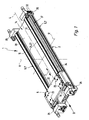
- linear guide device essentially comprises a guide structure 2 and in this regard, under execution of a working movement 3 along a major axis 4 linearly displaceable lifting 5.
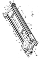
- the working movement 3 is in the case of the embodiment of FIGS. 1 and 2 caused jointly by two rodless linear actuators 6, in the case of the embodiment of Figures 3 and 4 of only a single rodless linear drive 6.
- Each linear drive 6 is part of the guide structure. 2
- the guide structure 2 comprises two parallel longitudinally spaced adjacent longitudinal beams 7, which are aligned parallel to the main axis 4. They have the same length among each other.
- the two longitudinal beams 7 extend in an in Figures 2 and 4 indicated main plane 8, which is spanned by the main axis 4 and a perpendicular transverse axis 12 of the guide structure 2.
- the two longitudinal beams 7 define between them, due to their mutual spacing, a gap 13.
- a connecting device 14 which connects the two longitudinal beams 7 while bridging the gap 13 firmly together, so that there is a rigid, self-supporting assembly.
- the connecting device 14 By accommodating the connecting device 14 in the intermediate space 13, it is achieved, inter alia, that the connecting device 14 does not act or only insignificantly on the height of the guide structure 2, which is measured in the direction of a vertical axis 11 perpendicular to the main plane 8.
- Each longitudinal beam 7 carries a parallel to the main axis 4 extending guide rail 15.
- This has expediently an undercut cross-sectional profile.
- it is profiled dovetail-shaped, as in FIG. 2 exemplarily expressed.
- the guide rails 15 are located in the same direction away from the main plane 8 longitudinal sides of the longitudinal beams 7, which are referred to as the better distinction as guide pages 16 below.
- the two guide rails 15 extend in both embodiments in a common, parallel to the main plane 8 guide plane 17th
- the guide rails 15 are fixedly mounted on each associated longitudinal beam 7, which may be with respect to the longitudinal members 7 separate or one-piece components.
- the lifting carriage 5 engages over the guide structure 2 in the region of the two guide rails 15.
- it preferably contains two carriages 18, which are mounted so as to be linearly displaceable on one of the guide rails 15 in the direction of the main axis 4, and at the end sections of the intermediate space 13 bridging support plate 22 are fastened, wherein the support plate 22 with any attachment means 23, for example, threaded holes or through holes, equipped, over which on the support plate 22 a from the lifting carriage 5 to be transported load can be fixed.
- the carriages 18 may be mounted on the guide rails 15 by sliding guide means and / or by rolling guide means.
- the support plate 22 and the carriage 18 form a one-piece unit.
- the lifting carriage 5 Since the lifting carriage 5 is supported at the same time on two spaced guide rails 15 transversely to the working movement 3, it is suitable for the transport of even heavy loads. Of course, can be transported and / or positioned with the linear drive device 1, if necessary, also loads with low weight.
- the two longitudinal beams 7 are independent, separate components, which are held only by the connecting device 14 in the desired assignment. They can therefore be manufactured individually and independently, which favors in particular the realization of large dimensions.
- the at least one rodless linear drive 6 is not in addition to the longitudinal members 7 component, but is executed in a unit with a longitudinal spar 7.
- one or both longitudinal beams 7 are formed directly by a rodless linear drive 6.
- the volume of construction occupied by the components of the linear drive device 1 can be kept low.
- the intermediate space 13 is not required for receiving a linear drive and is available for receiving a high rigidity connecting device 14.
- each longitudinal beam 7 of the associated guide rail 15 carrying longitudinal portion is suitably formed by a tubular body 24, whose length corresponds in particular to the length of the lifting carriage 5 fürfahrbaren stroke.
- End caps 25, 26 attached to the two end faces of a respective tubular body 24 form the frontal end of each longitudinal spar 7.
- the tubular body 24 acts as a tubular housing part 27, the interior of which forms a receiving space 28 for a driven member 29 of the relevant linear drive 6.
- the rodless linear actuators 6 are designed in fluid-actuated design, in which they are operated in particular with compressed air.
- the output member 29 is formed as a longitudinally of the receiving space 28 displaceable piston, which axially subdivides the receiving space 28 in two Beauftschungshuntn said so via control channels 32 in a coordinated manner can be acted upon with a pressure medium, that the output member 29 is driven to the working movement 3.
- each driven member 29 with the lifting carriage 5 via a driver member 33 which passes through a wall of the housing part 27 radially passing through longitudinal slot 34 which extends over the length of the housing part 27.
- a not further illustrated sealing tape is provided which sealingly abuts from the inside on the flanks of the longitudinal slot 34, wherein it can be lifted in the region of the output member 29 of the longitudinal slot to the inside to allow the passage of the driver member 33.
- This structure corresponds to that of a so-called slot cylinder known as such, so that further detailed explanations can be dispensed with.
- each driver member 33 engages, on the one hand, the output member 29 and, on the other hand, the lifting carriage 5, the latter in particular by driving coupling with the associated carriage 18.
- the lifting carriage 5 makes the movement of the drivingly coupled output members 29 synchronously.
- a mechanical coupling between the output member 29 and lifting 5 could also be a non-contact magnetic coupling.
- a longitudinal slot 34 in the housing part 27 could be dispensed with.
- At least one rodless linear drive 6 could also be designed as an electric linear drive.
- the output member 29 may be penetrated by a threaded hole with which it is on a is electrically driven to a rotational movement driven threaded spindle whose rotational motion is converted into a linear movement of the output member 29, which in turn is transferable via a driver member 33 or by magnetic coupling to the lifting carriage 5.
- the tubular body 24 is, in particular, a profiled extruded part which, for example, made of aluminum material, can be manufactured very inexpensively.
- the respective longitudinal slot 34 is arranged so that the driver member 33 passing him engages past the associated guide rail 15 at the longitudinal side facing away from the intermediate space 13.
- the longitudinal slot 34 is arranged so that its slot plane 35 with respect to the main plane 8 has an oblique course.
- the two slot planes 35 may in particular be arranged to form a V-shaped configuration, as shown in FIG FIG. 2 at 36 is illustrated.
- the longitudinal slots 34 in the housing part 27 or tubular body 24 are formed in the transition region between the guide side 16 and the outer side 37 facing away from the intermediate space 13.
- said outside 37 remains substantially unoccupied and can be used for any fastening measures, for example, for fastening the guide structure 2 to an external support structure or for attaching additional parts.
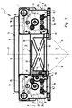
- the connecting devices 14 of both exemplary embodiments have in common that they each have at least one connecting body 38 arranged in the intermediate space 13 and bridging this intermediate space 13, which is fastened to both longitudinal bars 7 in such a way that a rigid assembly is defined by these components.
- the two embodiments differ in the number of connecting bodies 38 used.
- a single connector body 38 is present, which has a strip-shaped longitudinal shape and has a sufficiently large length to ensure the required connection stiffness. It expediently extends in the axial direction of the main axis 4 between the two end regions the longitudinal bars 7, wherein its length corresponds to the length of the tubular body 24 by way of example. Consequently, it can be surmounted by the front side of the end caps 25, 26 possibly attached to the tubular body 24.
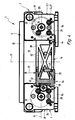
- the plurality of connecting bodies 38 are expediently designed identically to one another. Their number is based primarily on the desired length of the guide structure 2. There is here a modular structure, which makes it possible to use the connecting body 38 in terms of number and position variable. Compared with the design of the FIGS. 1 and 2 It is advantageous here that the connecting bodies 38 do not have to be cut to a specific length, but instead resort to a standardized, shorter overall length and then only the number of connecting bodies 38 varies.
- each connecting body 38 is penetrated in its longitudinal direction by at least one cavity 42 which opens out to its two end faces.
- a braced cross-sectional structure can be achieved, which has a high rigidity with low weight.
- the apparent from the drawing cross-sectional profiling has proven to be particularly useful.
- At least one cavity 42 may also be used to pass at least one fluidic and / or electrical conduit needed for operation of the linear guide device 1.
- at least one cavity 42 can also be used directly to the fluid guide.
- the connecting device 14 is designed to allow in a detachable manner a purely clamping attachment of the connecting body 38 at the respectively associated longitudinal beam 7.
- each longitudinal spar 7 may have a clamping strip 43 provided with an undercut cross-sectional profile on the outer surface facing the other longitudinal spar 7 and therefore the intermediate space 13.
- the terminal strip 43 extends continuously over the entire length of the tubular body 24, with which it may be integrally formed. As an example, it is profiled dovetail-shaped.
- the connecting body 38 is clamped via a respective clamping device 44 to the terminal block 43.
- a clamping device 44 is located in the region of the two outer sides of each connecting body 38 facing a longitudinal spar 7. It is advantageous if the clamping devices 44 are carried by the associated connecting body 38 so that they automatically engage in the installation of the connecting body 38 be placed in the desired location, which greatly simplifies handling.
- each clamping device 44 includes two in the direction of the vertical axis 11 spaced-apart retaining claws 45, 46 which are adjustable relative to each other in the axial direction of the vertical axis 11. They take a clamping position 43 on opposite longitudinal sides engages behind a clamping position and can be clamped by changing their relative position with the terminal block 43.
- the connecting body 38 in this case is supported over a large area on the associated longitudinal spar 7, in particular on the flat outer surface 47 of the clamping strip 43 facing it.
- each clamping device 44 expediently contains a manually actuatable actuator 48, possibly using a tool.
- This actuator is designed in particular as an adjusting screw mounted in the connecting body 38.
- each clamping device 44 includes a fixed and preferably integrally arranged on the connecting body 38 fixed retaining claw 45 which faces in the direction of the vertical axis 11 a relative to the connecting body 38 movable retaining claw 46 which cooperates with the actuator 48.
- the connecting body 38 can thus be hooked with its two fixed retaining claws 45 in the terminal block 43, to then actuate the movable holding claw 46 by actuation of the actuator 48 and to fix.
- the clamping movement of the movable holding claw 46 a linear movement, in the axial direction of the vertical axis 11.
- the clamping movement of the movable holding claw 46 is a pivotal movement.
- the actuator 48 acts on a transmission lever 52, which causes the pivotal movement of the movable holding claw 46.
- Each clamping device 44 may have only one pair of mutually associated retaining claws 45, 46, or via a plurality of in the direction of the main axis 4 successively arranged pairs of retaining claws.
- the connecting body 38 can be moved along the associated longitudinal spar 7 and positioned at the desired location.
- the at least one connecting body 38 can be arranged in its entirety within the intermediate space 13. In particular, it is placed in such a way that it terminates flush with the outer surfaces of the longitudinal members 7 opposite the guide sides 16. For lifting 5 toward a certain distance 53 is suitably maintained in the axial direction of the vertical axis 11, however.
- mounting plates 54 which can be used as interface elements and / or as an adapter for mounting the guide structure 2 on a support structure, such as a machine frame.
- a clamping portion may be formed by the groove flank of an undercut longitudinal groove, which is introduced into the outer circumference of the tubular body 24.
Landscapes
- Engineering & Computer Science (AREA)
- Physics & Mathematics (AREA)
- Fluid Mechanics (AREA)
- Mechanical Engineering (AREA)
- General Engineering & Computer Science (AREA)
- Actuator (AREA)
Claims (26)
- Dispositif d'entraînement linéaire doté de moyens de guidage pour charges lourdes, avec une structure de guidage (2) qui présente deux longerons (7) disposés parallèlement à distance l'un de l'autre, qui sont réunis en un sous-ensemble rigide par un dispositif de jonction (14) couvrant la distance transversale présente entre eux et qui portent chacun un rail de guidage (15) d'extension longitudinale, avec un chariot mobile (5) monté mobile linéairement sur les deux rails de guidage (15) et avec au moins un entraînement linéaire (6) sans tige de piston s'étendant le long de la course de déplacement du chariot mobile (5), dont l'organe de sortie (29) est couplé en entraînement avec le chariot mobile (5), caractérisé en ce que les deux longerons (7) de la structure de guidage (2) sont conformés en composants autonomes dont au moins l'un est formé par l'entraînement linéaire (6) sans tige de piston au nombre d'au moins un, le dispositif de jonction (14) étant placé dans l'intervalle (13) défini entre les deux longerons (7).
- Dispositif d'entraînement linéaire selon la revendication 1, caractérisé en ce que les deux longerons (7) sont formés chacun par un entraînement linéaire (6) sans tige de piston, les organes de sortie (29) des deux entraînements linéaires (6) étant couplés en entraînement au chariot mobile (5).
- Dispositif d'entraînement linéaire selon la revendication 1 ou 2, caractérisé en ce que l'entraînement linéaire (6) sans tige de piston au nombre d'au moins un est du type actionné par la force d'un fluide, en particulier au moyen d'air comprimé.
- Dispositif d'entraînement linéaire selon l'une des revendications 1 à 3, caractérisé en ce que l'entraînement linéaire (6) sans tige de piston au nombre d'au moins un est ce qu'on appelle un vérin à fente.
- Dispositif d'entraînement linéaire selon l'une des revendications 1 à 4, caractérisé en ce que la section de chaque longeron (7) portant le rail de guidage (15) est conformée en pièce profilée extrudée.
- Dispositif d'entraînement linéaire selon l'une des revendications 1 à 5, caractérisé en ce que chaque longeron (7) présente un corps tubulaire (24) portant le rail de guidage (15) associé.
- Dispositif d'entraînement linéaire selon la revendication 6, caractérisé en ce que le corps tubulaire (24) du longeron (7) conformé en entraînement linéaire (6) forme une partie boîtier (27) dans laquelle l'organe de sortie (29) de l'entraînement linéaire (6) est reçu de manière mobile linéairement.
- Dispositif d'entraînement linéaire selon la revendication 7, caractérisé en ce que la partie de boîtier (27) présente une fente longitudinale (34) à travers laquelle dépasse un organe d'entraînement (33) servant au couplage de l'organe de sortie (29) avec le chariot mobile (5).
- Dispositif d'entraînement linéaire selon la revendication 8, caractérisé en ce que, dans le cas de la configuration des deux longerons (7) en entraînements linéaires (6), les fentes longitudinales (34) des parties boîtier (27) sont disposées de telle manière que leurs plans de fente (35) s'étendent selon une configuration en V.
- Dispositif d'entraînement linéaire selon l'une des revendications 1 à 9, caractérisé en ce que les deux longerons (7) s'étendent dans un plan principal (8) commun traversant l'intervalle (13), les deux rails de guidage (15) étant placés sur des côtés longitudinaux des longerons (7) tournés dans la même direction et tournant le dos au plan principal (8).
- Dispositif d'entraînement linéaire selon la revendication 10, caractérisé en ce que le couplage d'entraînement entre l'organe de sortie (29) de l'entraînement linéaire (6) au nombre d'au moins un et le chariot mobile (5) est effectué sur le côté longitudinal extérieur du rail de guidage associé (15) qui est opposé à l'intervalle (13).
- Dispositif d'entraînement linéaire selon l'une des revendications 1 à 11, caractérisé en ce que le chariot mobile (5) possède deux corps mobiles (18) reliés rigidement l'un à l'autre par une plaque porteuse (22), qui sont montés coulissants chacun sur l'un des rails de guidage (15).
- Dispositif d'entraînement linéaire selon l'une des revendications 1 à 12, caractérisé en ce que le dispositif de jonction (14) présente au moins un corps de jonction (38) placé dans l'intervalle (13) entre les deux entraînements linéaires (6) et couvrant ainsi cet intervalle (13), corps qui est un composant séparé des deux longerons (7) et qui est fixé de telle manière sur les deux longerons (7) qu'il forme avec eux un sous-ensemble rigide.
- Dispositif d'entraînement linéaire selon la revendication 13, caractérisé en ce que le corps de jonction (38) au nombre d'au moins un est fixé de manière amovible aux deux longerons (7).
- Dispositif d'entraînement linéaire selon la revendication 13 ou 14, caractérisé en ce que le corps de jonction (38) est fixé exclusivement par coincement sur chaque longeron (7).
- Dispositif d'entraînement linéaire selon l'une des revendications 13 à 15, caractérisé en ce que le corps de jonction (38) au nombre d'au moins un est placé dans sa totalité à l'intérieur de l'intervalle (13) situé entre les deux longerons (7).
- Dispositif d'entraînement linéaire selon la revendication 16, caractérisé en ce que, du côté des longerons (7) opposé au chariot mobile (5), le corps de jonction (38) au nombre d'au moins un fait suite aux surfaces extérieures de ceux-ci sensiblement en affleurement, tandis qu'en direction du chariot mobile (5), une distance existe entre le corps de jonction (38) au nombre d'au moins un et les surfaces extérieures (16) des longerons (7) tournées vers le chariot mobile (5).
- Dispositif d'entraînement linéaire selon l'une des revendications 13 à 17, caractérisé en ce que le dispositif de jonction (14) dispose d'un unique corps de jonction (38) s'étendant, de manière avantageuse, d'une partie d'extrémité à l'autre des longerons (7).
- Dispositif d'entraînement linéaire selon l'une des revendications 13 à 17, caractérisé en ce que le dispositif de jonction (14) dispose de plusieurs corps de jonction (38) placés à distance les uns des autres le long des longerons (7) et fixés indépendamment les uns des autres sur les longerons (7).
- Dispositif d'entraînement linéaire selon la revendication 19, caractérisé par deux corps de jonction (38) extérieurs associés aux parties d'extrémité des longerons (7) et un autre corps de jonction (38) placé entre les précédents, en particulier au milieu.
- Dispositif d'entraînement linéaire selon l'une des revendications 13 à 20, caractérisé en ce que le corps de jonction (38) au nombre d'au moins un est traversé dans sa direction longitudinale par au moins une cavité (42) débouchant dans ses deux surfaces frontales.
- Dispositif d'entraînement linéaire selon l'une des revendications 13 à 21, caractérisé en ce qu'aux deux côtés longitudinaux du corps de jonction (38) au nombre d'au moins un tournés chacun vers un longeron (7) est associé un dispositif de blocage (44) par l'intermédiaire duquel le corps de jonction (38) est fixé par coincement sur le longeron (7) associé.
- Dispositif d'entraînement linéaire selon la revendication 22, caractérisé en ce que les dispositifs de blocage (44) sont portés par au moins un corps de jonction (38).
- Dispositif d'entraînement linéaire selon la revendication 22 ou 23, caractérisé en ce que chaque longeron (7) présente sur sa surface extérieure tournée vers l'autre longeron (7) au moins une barre de blocage (43) présentant un profil transversal à contre-dépouille, barre qui peut être saisie de manière bloquante par le dispositif de blocage (44) associé.
- Dispositif d'entraînement linéaire selon l'une des revendications 22 à 24, caractérisé en ce que chaque dispositif de blocage (44) présente deux griffes de maintien (45, 46) réglables l'une par rapport à l'autre, qui se mettent en prise de blocage sur une section de blocage du longeron (7) associé formée en particulier par une barre de blocage (43) présentant un profil transversal à contre-dépouille.
- Dispositif d'entraînement linéaire selon la revendication 25, caractérisé en ce que chaque dispositif de blocage (44) présente une griffe de maintien (45) stationnaire placée fixement et en particulier d'un seul tenant sur le corps de jonction (38), ainsi qu'une griffe de maintien (46) mobile par rapport à la précédente au moyen d'un organe de réglage (48) formé en particulier par une vis de réglage.
Applications Claiming Priority (1)
| Application Number | Priority Date | Filing Date | Title |
|---|---|---|---|
| DE200620013135 DE202006013135U1 (de) | 2006-08-26 | 2006-08-26 | Linearantriebseinrichtung mit Schwerlastführungsmitteln |
Publications (2)
| Publication Number | Publication Date |
|---|---|
| EP1892423A1 EP1892423A1 (fr) | 2008-02-27 |
| EP1892423B1 true EP1892423B1 (fr) | 2009-07-22 |
Family
ID=37402446
Family Applications (1)
| Application Number | Title | Priority Date | Filing Date |
|---|---|---|---|
| EP20070015056 Expired - Fee Related EP1892423B1 (fr) | 2006-08-26 | 2007-08-01 | Dispositif d'entraînement linéaire doté de moyens de guidage pour charges lourdes |
Country Status (3)
| Country | Link |
|---|---|
| EP (1) | EP1892423B1 (fr) |
| CN (1) | CN101131169A (fr) |
| DE (2) | DE202006013135U1 (fr) |
Families Citing this family (8)
| Publication number | Priority date | Publication date | Assignee | Title |
|---|---|---|---|---|
| EP2063132A1 (fr) | 2007-11-24 | 2009-05-27 | Festo AG & Co. KG | Dispositif d'entraînement linéaire |
| CN101737373B (zh) * | 2008-11-07 | 2012-07-04 | 沈阳芯源微电子设备有限公司 | 气缸和导轨的保护缓冲结构 |
| WO2011006517A1 (fr) | 2009-07-16 | 2011-01-20 | Festo Ag & Co. Kg | Machine de travail comportant au moins une unité d'entraînement |
| DE102010022625A1 (de) * | 2010-06-04 | 2011-12-08 | Festo Ag & Co. Kg | Handhabungssystem zur Handhabung von Gegenständen |
| CN104081068B (zh) * | 2012-02-04 | 2017-03-15 | 费斯托股份有限两合公司 | 线性引导装置 |
| US20160265563A1 (en) * | 2013-12-24 | 2016-09-15 | Festo Ag & Co. Kg | Linear Drive and Method for its Manufacture |
| CN104047916B (zh) * | 2014-06-04 | 2016-05-18 | 洛阳利维科技有限公司 | 一种同步动作的双油缸移动大负荷工作台的方法及装置 |
| CN104047913A (zh) * | 2014-06-04 | 2014-09-17 | 洛阳利维科技有限公司 | 一种相对式同心双活塞杆油缸移动大负荷工作台的装置 |
Family Cites Families (5)
| Publication number | Priority date | Publication date | Assignee | Title |
|---|---|---|---|---|
| SE468446B (sv) * | 1991-10-28 | 1993-01-18 | Leif Gullblom | Kopplingsanordning vid sammanstaellning av en kolvcylinder eller kolvstaangsloes cylinder med ett motsvarande arrangemang i form av en cylinder eller en gejdskena |
| JP3818752B2 (ja) * | 1997-09-24 | 2006-09-06 | Smc株式会社 | ロッドレスシリンダ |
| JP4228356B2 (ja) * | 1998-04-08 | 2009-02-25 | Smc株式会社 | ガイド機構 |
| ATE231221T1 (de) * | 2000-08-23 | 2003-02-15 | Festo Ag & Co | Kolbenstangenloser linearantrieb sowie zugehöriges gehäuse |
| WO2004067972A1 (fr) * | 2003-01-28 | 2004-08-12 | Koganei Corporation | Corps sous forme d'ensemble reuni, connecteur et unite verin hydraulique |
-
2006
- 2006-08-26 DE DE200620013135 patent/DE202006013135U1/de not_active Expired - Lifetime
-
2007
- 2007-08-01 DE DE200750001101 patent/DE502007001101D1/de active Active
- 2007-08-01 EP EP20070015056 patent/EP1892423B1/fr not_active Expired - Fee Related
- 2007-08-27 CN CNA2007101424909A patent/CN101131169A/zh active Pending
Also Published As
| Publication number | Publication date |
|---|---|
| CN101131169A (zh) | 2008-02-27 |
| DE502007001101D1 (de) | 2009-09-03 |
| EP1892423A1 (fr) | 2008-02-27 |
| DE202006013135U1 (de) | 2006-11-02 |
Similar Documents
| Publication | Publication Date | Title |
|---|---|---|
| EP1892423B1 (fr) | Dispositif d'entraînement linéaire doté de moyens de guidage pour charges lourdes | |
| EP3275628B1 (fr) | Bloc de poudre pour un dispositif de fabrication additive d'objets tridimensionnels | |
| WO2009039865A1 (fr) | Dispositif d'entraînement électrique linéaire direct avec un stator présentant deux rails de guidage pour le guidage linéaire d'un coulisseau entraîné | |
| EP2887513B1 (fr) | Système de moteur linéaire et machine-outil dotée d'un système de moteur linéaire | |
| DE3411823C3 (fr) | ||
| DE10162159B4 (de) | Linearstellglied mit Stoßdämpfungsmechanismus | |
| DE4408844A1 (de) | Anlage zur Bearbeitung und/oder Montage von Bauteilen | |
| EP2221491A1 (fr) | Dispositif de déplacement linéaire doté d'un passage de retour sans débit | |
| EP0918174B1 (fr) | Actionneur linéaire à entraínement motorisé | |
| DE3436946A1 (de) | Linearantrieb | |
| DE102005037322B4 (de) | Aufbau eines mit einem Motor ausstattbaren Linearroboters | |
| EP1075944A1 (fr) | Machine d'impression | |
| EP1034378A1 (fr) | Mecanisme d'entrainement lineaire | |
| EP1050685B1 (fr) | Glisseur hydraulique linéaire | |
| DE102009009011A1 (de) | Linearbewegungsvorrichtung mit teilweise abgestütztem Wälzflächenteil | |
| DE4230781C2 (de) | Druckmittelbetriebenes Linearmodul für Handling-Systeme | |
| EP2448712B1 (fr) | Machine de travail comportant au moins une unité d'entraînement | |
| DE10118534B4 (de) | Klemmsystem | |
| DE102014017976B3 (de) | Führungssystem | |
| DE102019120069A1 (de) | Anschlagmodul | |
| EP2063132A1 (fr) | Dispositif d'entraînement linéaire | |
| DE19611322C2 (de) | Antriebs- und Führungssystem | |
| DE102005049654B4 (de) | Anreihbare Ventil-Zylinder-Einheit mit einstückig hergestelltem Druckmittelverteiler sowie Ventil-Zylinder-Einheiten-Anordnung | |
| EP3024646A1 (fr) | Module de force et système de pressage modulaire | |
| DE19937806A1 (de) | Druckwerk |
Legal Events
| Date | Code | Title | Description |
|---|---|---|---|
| PUAI | Public reference made under article 153(3) epc to a published international application that has entered the european phase |
Free format text: ORIGINAL CODE: 0009012 |
|
| AK | Designated contracting states |
Kind code of ref document: A1 Designated state(s): AT BE BG CH CY CZ DE DK EE ES FI FR GB GR HU IE IS IT LI LT LU LV MC MT NL PL PT RO SE SI SK TR |
|
| AX | Request for extension of the european patent |
Extension state: AL BA HR MK YU |
|
| 17P | Request for examination filed |
Effective date: 20080229 |
|
| RAP1 | Party data changed (applicant data changed or rights of an application transferred) |
Owner name: FESTO AG & CO. KG |
|
| AKX | Designation fees paid |
Designated state(s): DE FR GB IT |
|
| GRAP | Despatch of communication of intention to grant a patent |
Free format text: ORIGINAL CODE: EPIDOSNIGR1 |
|
| GRAS | Grant fee paid |
Free format text: ORIGINAL CODE: EPIDOSNIGR3 |
|
| GRAA | (expected) grant |
Free format text: ORIGINAL CODE: 0009210 |
|
| AK | Designated contracting states |
Kind code of ref document: B1 Designated state(s): DE FR GB IT |
|
| REG | Reference to a national code |
Ref country code: GB Ref legal event code: FG4D Free format text: NOT ENGLISH |
|
| REF | Corresponds to: |
Ref document number: 502007001101 Country of ref document: DE Date of ref document: 20090903 Kind code of ref document: P |
|
| PGFP | Annual fee paid to national office [announced via postgrant information from national office to epo] |
Ref country code: FR Payment date: 20090819 Year of fee payment: 3 |
|
| PLBE | No opposition filed within time limit |
Free format text: ORIGINAL CODE: 0009261 |
|
| STAA | Information on the status of an ep patent application or granted ep patent |
Free format text: STATUS: NO OPPOSITION FILED WITHIN TIME LIMIT |
|
| 26N | No opposition filed |
Effective date: 20100423 |
|
| REG | Reference to a national code |
Ref country code: FR Ref legal event code: ST Effective date: 20110502 |
|
| PG25 | Lapsed in a contracting state [announced via postgrant information from national office to epo] |
Ref country code: FR Free format text: LAPSE BECAUSE OF NON-PAYMENT OF DUE FEES Effective date: 20100831 |
|
| PGFP | Annual fee paid to national office [announced via postgrant information from national office to epo] |
Ref country code: GB Payment date: 20110725 Year of fee payment: 5 |
|
| PGFP | Annual fee paid to national office [announced via postgrant information from national office to epo] |
Ref country code: IT Payment date: 20120803 Year of fee payment: 6 |
|
| GBPC | Gb: european patent ceased through non-payment of renewal fee |
Effective date: 20120801 |
|
| PG25 | Lapsed in a contracting state [announced via postgrant information from national office to epo] |
Ref country code: GB Free format text: LAPSE BECAUSE OF NON-PAYMENT OF DUE FEES Effective date: 20120801 |
|
| PGFP | Annual fee paid to national office [announced via postgrant information from national office to epo] |
Ref country code: DE Payment date: 20130628 Year of fee payment: 7 |
|
| PG25 | Lapsed in a contracting state [announced via postgrant information from national office to epo] |
Ref country code: IT Free format text: LAPSE BECAUSE OF NON-PAYMENT OF DUE FEES Effective date: 20130801 |
|
| REG | Reference to a national code |
Ref country code: DE Ref legal event code: R119 Ref document number: 502007001101 Country of ref document: DE |
|
| REG | Reference to a national code |
Ref country code: DE Ref legal event code: R119 Ref document number: 502007001101 Country of ref document: DE Effective date: 20150303 |
|
| PG25 | Lapsed in a contracting state [announced via postgrant information from national office to epo] |
Ref country code: DE Free format text: LAPSE BECAUSE OF NON-PAYMENT OF DUE FEES Effective date: 20150303 |