EP1892423B1 - Linear drive device with guide devices for heavy loads - Google Patents
Linear drive device with guide devices for heavy loads Download PDFInfo
- Publication number
- EP1892423B1 EP1892423B1 EP20070015056 EP07015056A EP1892423B1 EP 1892423 B1 EP1892423 B1 EP 1892423B1 EP 20070015056 EP20070015056 EP 20070015056 EP 07015056 A EP07015056 A EP 07015056A EP 1892423 B1 EP1892423 B1 EP 1892423B1
- Authority
- EP
- European Patent Office
- Prior art keywords
- linear drive
- longitudinal
- drive device
- connecting body
- linear
- Prior art date
- Legal status (The legal status is an assumption and is not a legal conclusion. Google has not performed a legal analysis and makes no representation as to the accuracy of the status listed.)
- Expired - Fee Related
Links
Images
Classifications
-
- F—MECHANICAL ENGINEERING; LIGHTING; HEATING; WEAPONS; BLASTING
- F15—FLUID-PRESSURE ACTUATORS; HYDRAULICS OR PNEUMATICS IN GENERAL
- F15B—SYSTEMS ACTING BY MEANS OF FLUIDS IN GENERAL; FLUID-PRESSURE ACTUATORS, e.g. SERVOMOTORS; DETAILS OF FLUID-PRESSURE SYSTEMS, NOT OTHERWISE PROVIDED FOR
- F15B15/00—Fluid-actuated devices for displacing a member from one position to another; Gearing associated therewith
- F15B15/08—Characterised by the construction of the motor unit
- F15B15/14—Characterised by the construction of the motor unit of the straight-cylinder type
- F15B15/1423—Component parts; Constructional details
- F15B15/1471—Guiding means other than in the end cap
-
- F—MECHANICAL ENGINEERING; LIGHTING; HEATING; WEAPONS; BLASTING
- F15—FLUID-PRESSURE ACTUATORS; HYDRAULICS OR PNEUMATICS IN GENERAL
- F15B—SYSTEMS ACTING BY MEANS OF FLUIDS IN GENERAL; FLUID-PRESSURE ACTUATORS, e.g. SERVOMOTORS; DETAILS OF FLUID-PRESSURE SYSTEMS, NOT OTHERWISE PROVIDED FOR
- F15B15/00—Fluid-actuated devices for displacing a member from one position to another; Gearing associated therewith
- F15B15/08—Characterised by the construction of the motor unit
- F15B15/082—Characterised by the construction of the motor unit the motor being of the slotted cylinder type
-
- F—MECHANICAL ENGINEERING; LIGHTING; HEATING; WEAPONS; BLASTING
- F15—FLUID-PRESSURE ACTUATORS; HYDRAULICS OR PNEUMATICS IN GENERAL
- F15B—SYSTEMS ACTING BY MEANS OF FLUIDS IN GENERAL; FLUID-PRESSURE ACTUATORS, e.g. SERVOMOTORS; DETAILS OF FLUID-PRESSURE SYSTEMS, NOT OTHERWISE PROVIDED FOR
- F15B15/00—Fluid-actuated devices for displacing a member from one position to another; Gearing associated therewith
- F15B15/08—Characterised by the construction of the motor unit
- F15B15/14—Characterised by the construction of the motor unit of the straight-cylinder type
- F15B15/1404—Characterised by the construction of the motor unit of the straight-cylinder type in clusters, e.g. multiple cylinders in one block
Definitions
- the invention relates to a linear drive device with heavy-load guiding means, with a guide structure having two longitudinally spaced along parallel alignment with longitudinal members, which are combined by a cross between them existing bridging connection means to form a rigid assembly and each carrying a longitudinal guide rail, with a the two guide rails linearly displaceably mounted lifting carriage and with at least one along the stroke of the lifting rod extending rodless linear drive, the output member is drivingly coupled to the lifting.
- Linear drive devices of this type are used in particular when relatively heavy components are to be displaced linearly and / or positioned, wherein they can also be used to construct multi-axis systems.
- a linear drive device of the type mentioned is known, which has two guide rails each carrying a longitudinal rails, which are an integral part of a U-shaped profile element. On the guide rails is a the space between the two longitudinal beams bridging Hubschlitten slidably mounted.
- the two longitudinal beams of the guide structure are designed as separate components, of which at least one of the at least one rodless linear drive is formed, wherein the connecting means is arranged in the space defined between the two longitudinal beams.
- the independent realization of the two longitudinal beams allows, together with the associated connection device, the realization of management structures of large size, so depending on the application with long length and / or large width and / or high altitude.
- the management structure is not to be manufactured here as a single component, but it is a production in smaller individual components possible, which are then assembled to the management structure.
- the at least one rodless linear drive is executed in unit with at least one of the longitudinal beams, no installation space is required for the installation of the linear drive to the longitudinal beams, which allows compact dimensions of the linear drive device, especially in the width direction, regardless of the currently selected size.
- the space between the two longitudinal beams can be used for space-saving accommodation of the connecting device.
- Another advantage is that through the integration of linear drive and longitudinal beam an automatic parallel alignment of guide means and drive means takes place, which simplifies the assembly of the linear drive device and still combines high precision with low susceptibility to wear during operation.
- both longitudinal beams are preferably designed in the form of rodless linear actuators, the output members at the same time drivingly on the lifting can act to perform synchronous operation an exact displacement of the lifting with high driving force can.
- the at least one rodless linear drive could be designed as an electric drive.
- a fluid-actuated linear drive is used, in particular a type which is designed for operation with compressed air. If both longitudinal beams formed by linear drives, a hybrid design is possible, wherein it is a linear drive to a fluidic linear drive and the other linear drive is an electric linear drive.
- a slot cylinder which has a tubular housing part, which is penetrated by a longitudinal slot which is penetrated by a driver element, via which the drive connection between the output member and lifting is made.
- An identically designed housing part can also be used in a longitudinal beam not designed as a linear drive, it being possible in this case to dispense with the output member in order to save costs.
- the use of identical parts for the guide rail-bearing component proves to be a further advantage.
- the preparation of a specifically designed, serving only for guiding purposes component can therefore be dispensed with.
- the guide rails are expediently arranged in the same direction and in this case by a longitudinal plane extending away from the main longitudinal plane extending between the two longitudinal members.
- the drive-like coupling between a respective output member and the lifting takes place expediently in the region of the opposite of the guide rail of the other longitudinal spar longitudinal side of the respective associated guide rail.
- the lifting carriage is particularly easy to implement if it has two separate, each mounted on one of the guide rails sliding carriage, which are interconnected via a rigid support plate. On the support plate fastening means may be provided for attaching the load to be transported.
- the connecting device preferably contains at least one connecting body, which is accommodated in the intermediate space between the two linear drives and thereby bridges this intermediate space.
- this at least one connecting body is an independent component, so that trouble-free production is possible independently of the longitudinal bars.
- the connecting body is ultimately attached to the two longitudinal beams, that together with these forms a rigid assembly, in particular a releasable attachment is present, so if necessary, a disassembly is possible, for example, if a linear drive must be replaced due to a defect.
- the fixing of the at least one connecting body is expediently exclusively by clamping on each longitudinal spar. An immediate screw connection is therefore unnecessary. This also simplifies fine adjustments of the individual components relative to each other during assembly of the linear drive device.
- a particularly compact arrangement results when the at least one connecting body is accommodated in its entirety within the intermediate space between the two longitudinal beams. It then protrudes disturbingly at neither of the two open sides of the gap. In particular, it can terminate flush with one of the two open sides of the intermediate space with the adjacent outer surfaces of the longitudinal members lying there.
- the connecting device contains only a single connecting body of the type described above, which expediently extends from one to the other end region of the two longitudinal struts, so that the latter does not protrude axially or only slightly beyond the connecting body. This results in a particularly rigid connection, which is predestined for the highest demands.
- connection means includes a plurality of mutually independent connection body, which are placed in the space with axial distance from each other and each cause a rigid connection between the two longitudinal beams. In this way, an extremely stable connection between the two longitudinal beams is still ensured, at the same time results in a not inconsiderable weight saving.
- At least one of the connecting bodies may be penetrated in its longitudinal direction by at least one cavity opening out to its two end faces.
- This cavity can serve alone to save weight, but it can also fulfill an additional function, for example, to guide a Fluids or for receiving electrical and / or fluidic conduit means.
- the at least one connecting body may be equipped with means that allow attachment of additional components present in addition to the longitudinal bars, for example holders for electrical and / or fluidic lines, for sensors, for position detecting means, for controls, such as valves or The like, and / or for an electronic control device used for the operation of the linear drive device.
- Each connecting body expediently associated with two clamping devices, via which the clamping attachment to the adjacent longitudinal spar is possible. It is advantageous if the connecting body carries the clamping devices, so that they do not need to be handled separately.
- each longitudinal bars each carry at least one clamping strip, which has an undercut cross-sectional profile, on the outer surfaces facing each other, with which the clamping devices can cooperate.
- each clamping device can have two retaining claws which can be adjusted relative to one another and which can engage in clamping manner on the clamping strip.
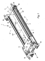
- linear guide device essentially comprises a guide structure 2 and in this regard, under execution of a working movement 3 along a major axis 4 linearly displaceable lifting 5.
- the working movement 3 is in the case of the embodiment of FIGS. 1 and 2 caused jointly by two rodless linear actuators 6, in the case of the embodiment of Figures 3 and 4 of only a single rodless linear drive 6.
- Each linear drive 6 is part of the guide structure. 2
- the guide structure 2 comprises two parallel longitudinally spaced adjacent longitudinal beams 7, which are aligned parallel to the main axis 4. They have the same length among each other.
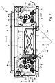
- the two longitudinal beams 7 extend in an in Figures 2 and 4 indicated main plane 8, which is spanned by the main axis 4 and a perpendicular transverse axis 12 of the guide structure 2.
- the two longitudinal beams 7 define between them, due to their mutual spacing, a gap 13.
- a connecting device 14 which connects the two longitudinal beams 7 while bridging the gap 13 firmly together, so that there is a rigid, self-supporting assembly.
- the connecting device 14 By accommodating the connecting device 14 in the intermediate space 13, it is achieved, inter alia, that the connecting device 14 does not act or only insignificantly on the height of the guide structure 2, which is measured in the direction of a vertical axis 11 perpendicular to the main plane 8.
- Each longitudinal beam 7 carries a parallel to the main axis 4 extending guide rail 15.
- This has expediently an undercut cross-sectional profile.
- it is profiled dovetail-shaped, as in FIG. 2 exemplarily expressed.
- the guide rails 15 are located in the same direction away from the main plane 8 longitudinal sides of the longitudinal beams 7, which are referred to as the better distinction as guide pages 16 below.
- the two guide rails 15 extend in both embodiments in a common, parallel to the main plane 8 guide plane 17th
- the guide rails 15 are fixedly mounted on each associated longitudinal beam 7, which may be with respect to the longitudinal members 7 separate or one-piece components.
- the lifting carriage 5 engages over the guide structure 2 in the region of the two guide rails 15.
- it preferably contains two carriages 18, which are mounted so as to be linearly displaceable on one of the guide rails 15 in the direction of the main axis 4, and at the end sections of the intermediate space 13 bridging support plate 22 are fastened, wherein the support plate 22 with any attachment means 23, for example, threaded holes or through holes, equipped, over which on the support plate 22 a from the lifting carriage 5 to be transported load can be fixed.
- the carriages 18 may be mounted on the guide rails 15 by sliding guide means and / or by rolling guide means.
- the support plate 22 and the carriage 18 form a one-piece unit.
- the lifting carriage 5 Since the lifting carriage 5 is supported at the same time on two spaced guide rails 15 transversely to the working movement 3, it is suitable for the transport of even heavy loads. Of course, can be transported and / or positioned with the linear drive device 1, if necessary, also loads with low weight.
- the two longitudinal beams 7 are independent, separate components, which are held only by the connecting device 14 in the desired assignment. They can therefore be manufactured individually and independently, which favors in particular the realization of large dimensions.
- the at least one rodless linear drive 6 is not in addition to the longitudinal members 7 component, but is executed in a unit with a longitudinal spar 7.
- one or both longitudinal beams 7 are formed directly by a rodless linear drive 6.
- the volume of construction occupied by the components of the linear drive device 1 can be kept low.
- the intermediate space 13 is not required for receiving a linear drive and is available for receiving a high rigidity connecting device 14.
- each longitudinal beam 7 of the associated guide rail 15 carrying longitudinal portion is suitably formed by a tubular body 24, whose length corresponds in particular to the length of the lifting carriage 5 fürfahrbaren stroke.
- End caps 25, 26 attached to the two end faces of a respective tubular body 24 form the frontal end of each longitudinal spar 7.
- the tubular body 24 acts as a tubular housing part 27, the interior of which forms a receiving space 28 for a driven member 29 of the relevant linear drive 6.
- the rodless linear actuators 6 are designed in fluid-actuated design, in which they are operated in particular with compressed air.
- the output member 29 is formed as a longitudinally of the receiving space 28 displaceable piston, which axially subdivides the receiving space 28 in two Beauftschungshuntn said so via control channels 32 in a coordinated manner can be acted upon with a pressure medium, that the output member 29 is driven to the working movement 3.
- each driven member 29 with the lifting carriage 5 via a driver member 33 which passes through a wall of the housing part 27 radially passing through longitudinal slot 34 which extends over the length of the housing part 27.
- a not further illustrated sealing tape is provided which sealingly abuts from the inside on the flanks of the longitudinal slot 34, wherein it can be lifted in the region of the output member 29 of the longitudinal slot to the inside to allow the passage of the driver member 33.
- This structure corresponds to that of a so-called slot cylinder known as such, so that further detailed explanations can be dispensed with.
- each driver member 33 engages, on the one hand, the output member 29 and, on the other hand, the lifting carriage 5, the latter in particular by driving coupling with the associated carriage 18.
- the lifting carriage 5 makes the movement of the drivingly coupled output members 29 synchronously.
- a mechanical coupling between the output member 29 and lifting 5 could also be a non-contact magnetic coupling.
- a longitudinal slot 34 in the housing part 27 could be dispensed with.
- At least one rodless linear drive 6 could also be designed as an electric linear drive.
- the output member 29 may be penetrated by a threaded hole with which it is on a is electrically driven to a rotational movement driven threaded spindle whose rotational motion is converted into a linear movement of the output member 29, which in turn is transferable via a driver member 33 or by magnetic coupling to the lifting carriage 5.
- the tubular body 24 is, in particular, a profiled extruded part which, for example, made of aluminum material, can be manufactured very inexpensively.
- the respective longitudinal slot 34 is arranged so that the driver member 33 passing him engages past the associated guide rail 15 at the longitudinal side facing away from the intermediate space 13.
- the longitudinal slot 34 is arranged so that its slot plane 35 with respect to the main plane 8 has an oblique course.
- the two slot planes 35 may in particular be arranged to form a V-shaped configuration, as shown in FIG FIG. 2 at 36 is illustrated.
- the longitudinal slots 34 in the housing part 27 or tubular body 24 are formed in the transition region between the guide side 16 and the outer side 37 facing away from the intermediate space 13.
- said outside 37 remains substantially unoccupied and can be used for any fastening measures, for example, for fastening the guide structure 2 to an external support structure or for attaching additional parts.
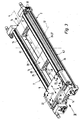
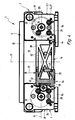
- the connecting devices 14 of both exemplary embodiments have in common that they each have at least one connecting body 38 arranged in the intermediate space 13 and bridging this intermediate space 13, which is fastened to both longitudinal bars 7 in such a way that a rigid assembly is defined by these components.
- the two embodiments differ in the number of connecting bodies 38 used.
- a single connector body 38 is present, which has a strip-shaped longitudinal shape and has a sufficiently large length to ensure the required connection stiffness. It expediently extends in the axial direction of the main axis 4 between the two end regions the longitudinal bars 7, wherein its length corresponds to the length of the tubular body 24 by way of example. Consequently, it can be surmounted by the front side of the end caps 25, 26 possibly attached to the tubular body 24.
- the plurality of connecting bodies 38 are expediently designed identically to one another. Their number is based primarily on the desired length of the guide structure 2. There is here a modular structure, which makes it possible to use the connecting body 38 in terms of number and position variable. Compared with the design of the FIGS. 1 and 2 It is advantageous here that the connecting bodies 38 do not have to be cut to a specific length, but instead resort to a standardized, shorter overall length and then only the number of connecting bodies 38 varies.
- each connecting body 38 is penetrated in its longitudinal direction by at least one cavity 42 which opens out to its two end faces.
- a braced cross-sectional structure can be achieved, which has a high rigidity with low weight.
- the apparent from the drawing cross-sectional profiling has proven to be particularly useful.
- At least one cavity 42 may also be used to pass at least one fluidic and / or electrical conduit needed for operation of the linear guide device 1.
- at least one cavity 42 can also be used directly to the fluid guide.
- the connecting device 14 is designed to allow in a detachable manner a purely clamping attachment of the connecting body 38 at the respectively associated longitudinal beam 7.
- each longitudinal spar 7 may have a clamping strip 43 provided with an undercut cross-sectional profile on the outer surface facing the other longitudinal spar 7 and therefore the intermediate space 13.
- the terminal strip 43 extends continuously over the entire length of the tubular body 24, with which it may be integrally formed. As an example, it is profiled dovetail-shaped.
- the connecting body 38 is clamped via a respective clamping device 44 to the terminal block 43.
- a clamping device 44 is located in the region of the two outer sides of each connecting body 38 facing a longitudinal spar 7. It is advantageous if the clamping devices 44 are carried by the associated connecting body 38 so that they automatically engage in the installation of the connecting body 38 be placed in the desired location, which greatly simplifies handling.
- each clamping device 44 includes two in the direction of the vertical axis 11 spaced-apart retaining claws 45, 46 which are adjustable relative to each other in the axial direction of the vertical axis 11. They take a clamping position 43 on opposite longitudinal sides engages behind a clamping position and can be clamped by changing their relative position with the terminal block 43.
- the connecting body 38 in this case is supported over a large area on the associated longitudinal spar 7, in particular on the flat outer surface 47 of the clamping strip 43 facing it.
- each clamping device 44 expediently contains a manually actuatable actuator 48, possibly using a tool.
- This actuator is designed in particular as an adjusting screw mounted in the connecting body 38.
- each clamping device 44 includes a fixed and preferably integrally arranged on the connecting body 38 fixed retaining claw 45 which faces in the direction of the vertical axis 11 a relative to the connecting body 38 movable retaining claw 46 which cooperates with the actuator 48.
- the connecting body 38 can thus be hooked with its two fixed retaining claws 45 in the terminal block 43, to then actuate the movable holding claw 46 by actuation of the actuator 48 and to fix.
- the clamping movement of the movable holding claw 46 a linear movement, in the axial direction of the vertical axis 11.
- the clamping movement of the movable holding claw 46 is a pivotal movement.
- the actuator 48 acts on a transmission lever 52, which causes the pivotal movement of the movable holding claw 46.
- Each clamping device 44 may have only one pair of mutually associated retaining claws 45, 46, or via a plurality of in the direction of the main axis 4 successively arranged pairs of retaining claws.
- the connecting body 38 can be moved along the associated longitudinal spar 7 and positioned at the desired location.
- the at least one connecting body 38 can be arranged in its entirety within the intermediate space 13. In particular, it is placed in such a way that it terminates flush with the outer surfaces of the longitudinal members 7 opposite the guide sides 16. For lifting 5 toward a certain distance 53 is suitably maintained in the axial direction of the vertical axis 11, however.
- mounting plates 54 which can be used as interface elements and / or as an adapter for mounting the guide structure 2 on a support structure, such as a machine frame.
- a clamping portion may be formed by the groove flank of an undercut longitudinal groove, which is introduced into the outer circumference of the tubular body 24.
Description
Die Erfindung betrifft eine Linearantriebseinrichtung mit Schwerlastführungsmitteln, mit einer Führungsstruktur, die zwei unter Parallelausrichtung mit Abstand nebeneinander angeordnete Längsholme aufweist, die durch eine den zwischen ihnen vorhandenen Querabstand überbrückende Verbindungseinrichtung zu einer starren Baugruppe zusammengefasst sind und die jeweils eine längsverlaufende Führungsschiene tragen, mit einem an den beiden Führungsschienen linear verschiebbar gelagerten Hubschlitten und mit mindestens einem sich längs der Hubstrecke des Hubschlittens erstreckenden kolbenstangenlosen Linearantrieb, dessen Abtriebsglied mit dem Hubschlitten antriebsmäßig gekoppelt ist.The invention relates to a linear drive device with heavy-load guiding means, with a guide structure having two longitudinally spaced along parallel alignment with longitudinal members, which are combined by a cross between them existing bridging connection means to form a rigid assembly and each carrying a longitudinal guide rail, with a the two guide rails linearly displaceably mounted lifting carriage and with at least one along the stroke of the lifting rod extending rodless linear drive, the output member is drivingly coupled to the lifting.
Linearantriebseinrichtungen dieser Art werden insbesondere dann eingesetzt, wenn relativ schwere Komponenten linear zu verlagern und/oder zu positionieren sind, wobei sie auch zum Aufbau von Mehrachssystemen eingesetzt werden können. Aus dem Katalog "
Es ist die Aufgabe der vorliegenden Erfindung, eine für Schwerlastanwendungen geeignete Linearantriebseinrichtung zu schaffen, die auch bei großen Baugrößen mit kompaktem Bauvolumen realisierbar ist und dabei mit geringem Aufwand eine hohe Fertigungspräzision ermöglicht.It is the object of the present invention to provide a suitable for heavy-duty applications linear drive device that can be realized even with large sizes with a compact size and thereby allows low cost high manufacturing precision.
Zu Lösung dieser Aufgabe ist vorgesehen, dass die beiden Längsholme der Führungsstruktur als eigenständige Komponenten ausgeführt sind, von denen mindestens eine von dem mindestens einen kolbenstangenlosen Linearantrieb gebildet ist, wobei die Verbindungseinrichtung in dem zwischen den beiden Längsholmen definierten Zwischenraum angeordnet ist.To solve this problem it is provided that the two longitudinal beams of the guide structure are designed as separate components, of which at least one of the at least one rodless linear drive is formed, wherein the connecting means is arranged in the space defined between the two longitudinal beams.
Die voneinander unabhängige Realisierung der beiden Längsholme ermöglicht, gemeinsam mit der zugeordneten Verbindungseinrichtung, die Realisierung von Führungsstrukturen großer Baugröße, also vom Anwendungsfall abhängend mit großer Länge und/oder großer Breite und/oder großer Höhe. Die Führungsstruktur ist hier nicht als einheitliches Bauteil zu fertigen, sondern es ist eine Fertigung in kleineren Einzelkomponenten möglich, die erst anschließend zu der Führungsstruktur zusammengesetzt werden. Indem der mindestens eine kolbenstangenlose Linearantrieb in Baueinheit mit mindestens einem der Längsholme ausgeführt ist, wird für die Installation des Linearantriebes kein zu den Längsholmen zusätzlicher Einbauraum benötigt, was ungeachtet der momentan gewählten Baugröße kompakte Abmessungen der Linearantriebseinrichtung, vor allem in der Breitenrichtung, ermöglicht. Der Zwischenraum zwischen den beiden Längsholmen kann zur platzsparenden Unterbringung der Verbindungseinrichtung genutzt werden.The independent realization of the two longitudinal beams allows, together with the associated connection device, the realization of management structures of large size, so depending on the application with long length and / or large width and / or high altitude. The management structure is not to be manufactured here as a single component, but it is a production in smaller individual components possible, which are then assembled to the management structure. By the at least one rodless linear drive is executed in unit with at least one of the longitudinal beams, no installation space is required for the installation of the linear drive to the longitudinal beams, which allows compact dimensions of the linear drive device, especially in the width direction, regardless of the currently selected size. The space between the two longitudinal beams can be used for space-saving accommodation of the connecting device.
Ein weiterer Vorteil besteht darin, dass durch die Integration von Linearantrieb und Längsholm eine automatische Parallelausrichtung von Führungsmitteln und Antriebsmitteln stattfindet, was den Zusammenbau der Linearantriebseinrichtung vereinfacht und dennoch im Betrieb eine hohe Präzision mit geringer Verschleißanfälligkeit verbindet.Another advantage is that through the integration of linear drive and longitudinal beam an automatic parallel alignment of guide means and drive means takes place, which simplifies the assembly of the linear drive device and still combines high precision with low susceptibility to wear during operation.
Insbesondere wenn nur verhältnismäßig geringe Lasten zu transportieren sind und/oder bei einem Betrieb mit horizontal ausgerichteter Hubstrecke des Hubschlittens genügt es, wenn nur einer der beiden Längsholme von einem kolbenstangenlosen Linearantrieb gebildet ist. Der andere Längsholm übernimmt dann ausschließlich Führungsaufgaben. Vor allem bei schwereren Lasten, insbesondere in Verbindung mit vertikal orientierter Hubstrecke, sind bevorzugt beide Längsholme in Gestalt von kolbenstangenlosen Linearantrieben ausgeführt, deren Abtriebsglieder gleichzeitig antriebsmäßig auf den Hubschlitten einwirken können, um bei Synchronbetrieb eine exakte Verlagerung des Hubschlittens mit hoher Antriebskraft durchführen zu können.In particular, if only relatively small loads are to be transported and / or in an operation with horizontally aligned stroke length of the lifting carriage, it is sufficient if only one of the two longitudinal beams is formed by a rodless linear drive. The other longitudinal spar then takes over exclusively management duties. Especially in heavier loads, especially in conjunction with vertically oriented stroke distance, both longitudinal beams are preferably designed in the form of rodless linear actuators, the output members at the same time drivingly on the lifting can act to perform synchronous operation an exact displacement of the lifting with high driving force can.
Vorteilhafte Weiterbildungen der Erfindung gehen aus den Unteransprüchen hervor.Advantageous developments of the invention will become apparent from the dependent claims.
Der mindestens eine kolbenstangenlose Linearantrieb könnte als elektrischer Antrieb konzipiert sein. Vorzugsweise kommt jedoch ein fluidbetätigter Linearantrieb zum Einsatz, insbesondere ein Typ, der für einen Betrieb mit Druckluft ausgelegt ist. Sind beide Längsholme von Linearantrieben gebildet, ist auch eine Hybridausgestaltung möglich, wobei es sich bei dem einen Linearantrieb um einen fluidischen Linearantrieb und bei dem anderen Linearantrieb um einen elektrischen Linearantrieb handelt.The at least one rodless linear drive could be designed as an electric drive. Preferably, however, a fluid-actuated linear drive is used, in particular a type which is designed for operation with compressed air. If both longitudinal beams formed by linear drives, a hybrid design is possible, wherein it is a linear drive to a fluidic linear drive and the other linear drive is an electric linear drive.
Ungeachtet vom Typ des Linearantriebes liegt zweckmäßigerweise eine Ausgestaltung als Schlitzzylinder vor, der über ein rohrförmiges Gehäuseteil verfügt, welches von einem Längsschlitz durchsetzt ist, der von einem Mitnehmerglied durchgriffen ist, über das die Antriebsverbindung zwischen Abtriebsglied und Hubschlitten vorgenommen ist.Regardless of the type of linear drive is expediently an embodiment as a slot cylinder, which has a tubular housing part, which is penetrated by a longitudinal slot which is penetrated by a driver element, via which the drive connection between the output member and lifting is made.
Ein identisch gestaltetes Gehäuseteil kann auch bei einem nicht als Linearantrieb konzipierten Längsholm Verwendung finden, wobei man in diesem Fall zur Einsparung von Kosten auf das Abtriebsglied verzichten kann. Die Verwendung von Gleichteilen für das die Führungsschiene tragende Bauteil erweist sich hierbei als weiterer Vorteil. Auf die Herstellung eines spezifisch gestalteten, lediglich den Führungszwecken dienenden Bauteils kann mithin verzichtet werden.An identically designed housing part can also be used in a longitudinal beam not designed as a linear drive, it being possible in this case to dispense with the output member in order to save costs. The use of identical parts for the guide rail-bearing component proves to be a further advantage. The preparation of a specifically designed, serving only for guiding purposes component can therefore be dispensed with.
Die Führungsschienen sind zweckmäßigerweise an in die gleiche Richtung und hierbei von einer zwischen den beiden Längsholmen verlaufenden Hauptebene weg weisenden Längsseiten der Längsholme angeordnet. Die antriebsmäßige Kopplung zwischen einem jeweiligen Abtriebsglied und dem Hubschlitten findet hierbei zweckmäßigerweise im Bereich der von der Führungsschiene des anderen Längsholmes entgegengesetzten Längsseite der jeweils zugeordneten Führungsschiene statt.The guide rails are expediently arranged in the same direction and in this case by a longitudinal plane extending away from the main longitudinal plane extending between the two longitudinal members. The drive-like coupling between a respective output member and the lifting takes place expediently in the region of the opposite of the guide rail of the other longitudinal spar longitudinal side of the respective associated guide rail.
Der Hubschlitten lässt sich besonders einfach realisieren, wenn er über zwei gesonderte, jeweils an einer der Führungsschienen verschiebbar gelagerte Laufwagen verfügt, die über eine starre Tragplatte miteinander verbunden sind. An der Tragplatte können Befestigungsmittel zum Anbringen der zu transportierenden Last vorgesehen sein.The lifting carriage is particularly easy to implement if it has two separate, each mounted on one of the guide rails sliding carriage, which are interconnected via a rigid support plate. On the support plate fastening means may be provided for attaching the load to be transported.
Vorzugsweise enthält die Verbindungseinrichtung mindestens einen Verbindungskörper, der in dem Zwischenraum zwischen den beiden Linearantrieben aufgenommen ist und dabei diesen Zwischenraum überbrückt. Bei diesem mindestens einen Verbindungskörper handelt es sich wie bei den beiden Längsholmen um eine eigenständige Komponente, sodass eine problemlose Fertigung unabhängig von den Längsholmen möglich ist. Der Verbindungskörper ist letztlich so an den beiden Längsholmen befestigt, dass er gemeinsam mit diesen eine starre Baugruppe bildet, wobei insbesondere eine lösbare Befestigung vorliegt, sodass bei Bedarf eine Zerlegung möglich ist, beispielsweise wenn ein Linearantrieb aufgrund eines Defektes ausgetauscht werden muss.The connecting device preferably contains at least one connecting body, which is accommodated in the intermediate space between the two linear drives and thereby bridges this intermediate space. As with the two longitudinal bars, this at least one connecting body is an independent component, so that trouble-free production is possible independently of the longitudinal bars. The connecting body is ultimately attached to the two longitudinal beams, that together with these forms a rigid assembly, in particular a releasable attachment is present, so if necessary, a disassembly is possible, for example, if a linear drive must be replaced due to a defect.
Die Fixierung des mindestens einen Verbindungskörpers erfolgt an jedem Längsholm zweckmäßigerweise ausschließlich klemmend. Eine unmittelbare Schraubverbindung erübrigt sich daher. Dies vereinfacht auch Feinjustierungen der einzelnen Komponenten relativ zueinander beim Zusammenbau der Linearantriebseinrichtung. Eine besonders kompakte Anordnung ergibt sich, wenn der mindestens eine Verbindungskörper in seiner Gesamtheit innerhalb des Zwischenraumes zwischen den beiden Längsholmen aufgenommen ist. Er ragt dann an keiner der beiden offenen Seiten des Zwischenraumes störend hinaus. Insbesondere kann er an einer der beiden offenen Seiten des Zwischenraumes bündig mit den dort liegenden benachbarten Außenflächen der Längsholme abschließen.The fixing of the at least one connecting body is expediently exclusively by clamping on each longitudinal spar. An immediate screw connection is therefore unnecessary. This also simplifies fine adjustments of the individual components relative to each other during assembly of the linear drive device. A particularly compact arrangement results when the at least one connecting body is accommodated in its entirety within the intermediate space between the two longitudinal beams. It then protrudes disturbingly at neither of the two open sides of the gap. In particular, it can terminate flush with one of the two open sides of the intermediate space with the adjacent outer surfaces of the longitudinal members lying there.
Bei einer möglichen Ausführungsform enthält die Verbindungseinrichtung lediglich einen einzige Verbindungskörper der vorstehend erläuterten Art, der sich hierbei zweckmäßigerweise vom einen bis zum anderen Endbereich der beiden Längsholme erstreckt, sodass Letztere nicht oder nur geringfügig axial über den Verbindungskörper hinausragen. Hieraus resultiert eine besonders steife Verbindung, die für höchste Ansprüche prädestiniert ist.In one possible embodiment, the connecting device contains only a single connecting body of the type described above, which expediently extends from one to the other end region of the two longitudinal struts, so that the latter does not protrude axially or only slightly beyond the connecting body. This results in a particularly rigid connection, which is predestined for the highest demands.
Bei einer alternativen Bauform enthält die Verbindungseinrichtung mehrere voneinander unabhängige Verbindungskörper, die in dem Zwischenraum mit axialem Abstand zueinander platziert sind und jeweils eine starre Verbindung zwischen den beiden Längsholmen bewirken. Auf diese Weise ist weiterhin eine äußerst stabile Verbindung zwischen den beiden Längsholmen gewährleistet, wobei sich gleichzeitig eine nicht unbeträchtliche Gewichtseinsparung ergibt.In an alternative design, the connection means includes a plurality of mutually independent connection body, which are placed in the space with axial distance from each other and each cause a rigid connection between the two longitudinal beams. In this way, an extremely stable connection between the two longitudinal beams is still ensured, at the same time results in a not inconsiderable weight saving.
Mindestens einer der Verbindungskörper kann in seiner Längsrichtung von mindestens einem zu seinen beiden Stirnflächen ausmündenden Hohlraum durchsetzt sein. Dieser Hohlraum kann allein zur Gewichtseinsparung dienen, doch kann er auch eine Zusatzfunktion erfüllen, beispielsweise zur Führung eines Fluides oder zur Aufnahme von elektrischen und/oder fluidischen Leitungsmitteln.At least one of the connecting bodies may be penetrated in its longitudinal direction by at least one cavity opening out to its two end faces. This cavity can serve alone to save weight, but it can also fulfill an additional function, for example, to guide a Fluids or for receiving electrical and / or fluidic conduit means.
Auch unabhängig von mindestens einem Hohlraum kann der mindestens eine Verbindungskörper mit Mitteln ausgestattet sein, die eine Anbringung von zusätzlich zu den Längsholmen vorhandenen Zusatzbauteilen ermöglichen, beispielsweise Halterungen für elektrische und/oder fluidische Leitungen, für Sensoren, für Positionserfassungsmittel, für Steuerelemente, wie Ventile oder dergleichen, und/oder für eine für den Betrieb der Linearantriebseinrichtung verwendete elektronische Steuereinrichtung.Also independent of at least one cavity, the at least one connecting body may be equipped with means that allow attachment of additional components present in addition to the longitudinal bars, for example holders for electrical and / or fluidic lines, for sensors, for position detecting means, for controls, such as valves or The like, and / or for an electronic control device used for the operation of the linear drive device.
Jedem Verbindungskörper sind zweckmäßigerweise zwei Klemmvorrichtungen zugeordnet, über die die Klemmbefestigung am benachbarten Längsholm möglich ist. Es ist von Vorteil, wenn der Verbindungskörper die Klemmvorrichtungen trägt, sodass diese nicht gesondert gehandhabt werden müssen.Each connecting body expediently associated with two clamping devices, via which the clamping attachment to the adjacent longitudinal spar is possible. It is advantageous if the connecting body carries the clamping devices, so that they do not need to be handled separately.
Zweckmäßigerweise tragen die Längsholme an den einander zugewandten Außenflächen je mindestens eine über ein hinterschnittenes Querschnittsprofil verfügende Klemmleiste, mit der die Klemmvorrichtungen zusammenwirken können. Jede Klemmvorrichtung kann insbesondere zwei relativ zueinander verstellbare Halteklauen aufweisen, die an der Klemmleiste klemmend angreifen können.Expediently, the longitudinal bars each carry at least one clamping strip, which has an undercut cross-sectional profile, on the outer surfaces facing each other, with which the clamping devices can cooperate. In particular, each clamping device can have two retaining claws which can be adjusted relative to one another and which can engage in clamping manner on the clamping strip.
Nachfolgend wird die Erfindung anhand der beiliegenden Zeichnung näher erläutert. In dieser zeigen:
Figur 1- eine bevorzugte erste Bauform der erfindungsgemäßen Linearantriebseinrichtung, die mit einem einzigen Verbindungskörper ausgestattet ist, in einer perspektivischen Darstellung,
Figur 2- die Anordnung aus
Figur 1 - Figur 3
- eine weitere Ausführungsform der Linearantriebseinrichtung, die mit mehreren, beabstandet zueinander aufeinanderfolgend angeordneten Verbindungskörpern ausgestattet ist, wiederum in einer perspektivischen Ansicht, und
- Figur 4
- die Anordnung aus
Figur 3 in einer teilweise aufgebrochenen Stirnansicht mit Blickrichtung gemäß Pfeil IV.
- FIG. 1
- A preferred first design of the linear drive device according to the invention, which is equipped with a single connector body, in a perspective view,
- FIG. 2
- the arrangement
FIG. 1 in an end view looking in the direction of arrow II, partially broken, - FIG. 3
- a further embodiment of the linear drive device, which is equipped with a plurality of mutually spaced successively arranged connecting bodies, again in a perspective view, and
- FIG. 4
- the arrangement
FIG. 3 in a partially broken front view with viewing direction according to arrow IV.
Die gesamthaft mit Bezugsziffer 1 bezeichnete Linearführungseinrichtung enthält im Wesentlichen eine Führungsstruktur 2 und einen diesbezüglich unter Ausführung einer Arbeitsbewegung 3 längs einer Hauptachse 4 linear verschiebbaren Hubschlitten 5. Die Arbeitsbewegung 3 wird im Falle des Ausführungsbeispiels der
Die Führungsstruktur 2 enthält zwei mit paralleler Ausrichtung mit Abstand längsseits nebeneinander angeordnete Längsholme 7, die parallel zu der Hauptachse 4 ausgerichtet sind. Sie haben untereinander die gleiche Länge.The
Die beiden Längsholme 7 erstrecken sich in einer in
Die beiden Längsholme 7 definieren zwischen sich, aufgrund ihrer gegenseitigen Beabstandung, einen Zwischenraum 13. In diesem befindet sich eine Verbindungseinrichtung 14, die die beiden Längsholme 7 unter Überbrückung des Zwischenraumes 13 fest miteinander verbindet, sodass sich eine starre, selbsttragende Baugruppe ergibt.The two
Durch die Unterbringung der Verbindungseinrichtung 14 in dem Zwischenraum 13 wird unter anderem erreicht, dass sich die Verbindungseinrichtung 14 nicht oder nur unwesentlich auf die Bauhöhe der Führungsstruktur 2 auswirkt, die in Richtung einer zu der Hauptebene 8 rechtwinkeligen Hochachse 11 gemessen wird.By accommodating the connecting
Jeder Längsholm 7 trägt eine parallel zu der Hauptachse 4 verlaufende Führungsschiene 15. Diese hat zweckmäßigerweise ein hinterschnittenes Querschnittsprofil. Bevorzugt ist sie schwalbenschwanzförmig profiliert, wie dies in
Die Führungsschienen 15 befinden sich an in die gleiche Richtung von der Hauptebene 8 wegweisenden Längsseiten der Längsholme 7, die im Folgenden der besseren Unterscheidung wegen als Führungsseiten 16 bezeichnet seien. Die beiden Führungsschienen 15 verlaufen bei beiden Ausführungsbeispielen in einer gemeinsamen, zu der Hauptebene 8 parallelen Führungsebene 17.The guide rails 15 are located in the same direction away from the main plane 8 longitudinal sides of the
Die Führungsschienen 15 sind fest am jeweils zugeordneten Längsholm 7 angebracht, wobei es sich um bezüglich der Längsholme 7 separate oder auch einstückige Komponenten handeln kann.The guide rails 15 are fixedly mounted on each associated
Der Hubschlitten 5 übergreift die Führungsstruktur 2 im Bereich der beiden Führungsschienen 15. Dabei überbrückt er den Zwischenraum 13. Bevorzugt enthält er zwei an jeweils einer der Führungsschienen 15 in Richtung der Hauptachse 4 linear verschiebbar gelagerte Laufwagen 18, die an den Endabschnitten einer den Zwischenraum 13 überbrückenden Tragplatte 22 befestigt sind, wobei die Tragplatte 22 mit beliebigen Befestigungsmitteln 23, beispielsweise Gewindebohrungen oder Durchgangsbohrungen, ausgestattet ist, über die an der Tragplatte 22 eine vom Hubschlitten 5 zu transportierende Last fixierbar ist.The lifting
Die Laufwagen 18 können durch Gleitführungsmittel und/oder durch Wälzführungsmittel an den Führungsschienen 15 gelagert sein.The
Bei einer nicht dargestellten Ausführungsform bilden die Tragplatte 22 und die Laufwagen 18 eine einstückige Baueinheit.In one embodiment, not shown, the
Da der Hubschlitten 5 gleichzeitig an zwei zueinander beabstandeten Führungsschienen 15 quer zu der Arbeitsbewegung 3 abgestützt ist, eignet er sich für den Transport auch schwerer Lasten. Selbstverständlich können mit der Linearantriebseinrichtung 1 bei Bedarf auch Lasten mit geringem Gewicht transportiert und/oder positioniert werden.Since the lifting
Die beiden Längsholme 7 sind eigenständige, separate Komponenten, die nur durch die Verbindungseinrichtung 14 in der gewünschten Zuordnung gehalten sind. Sie können daher einzeln und unabhängig voneinander gefertigt werden, was insbesondere auch die Realisierung großer Abmessungen begünstigt.The two
Ein weiteres charakteristisches Merkmal der Linearantriebseinrichtung 1 besteht darin, dass der mindestens eine kolbenstangenlose Linearantrieb 6 keine zusätzlich zu den Längsholmen 7 vorhandene Komponente ist, sondern in Baueinheit mit einem Längsholm 7 ausgeführt ist. Mit anderen Worten werden ein oder beide Längsholme 7 unmittelbar von einem kolbenstangenlosen Linearantrieb 6 gebildet. Somit kann das von den Komponenten der Linearantriebseinrichtung 1 eingenommene Bauvolumen gering gehalten werden. Insbesondere wird der Zwischenraum 13 nicht zur Aufnahme eines Linearantriebes benötigt und steht zur Aufnahme einer eine hohe Steifigkeit aufweisenden Verbindungseinrichtung 14 zur Verfügung.Another characteristic feature of the
Bei jedem Längsholm 7 ist der die zugeordnete Führungsschiene 15 tragende Längenabschnitt zweckmäßigerweise von einem Rohrkörper 24 gebildet, dessen Länge insbesondere der Länge der vom Hubschlitten 5 durchfahrbaren Hubstrecke entspricht. An die beiden Stirnseiten eines jeweiligen Rohrkörpers 24 angesetzte Abschlussdeckel 25, 26 bilden den stirnseitigen Abschluss jedes Längsholmes 7.In each
In den Fällen, in denen der Längsholm 7 von einem kolbenstangenlosen Linearantrieb 6 gebildet ist, fungiert der Rohrkörper 24 als rohrförmiges Gehäuseteil 27, dessen Innenraum einen Aufnahmeraum 28 für ein Abtriebsglied 29 des betreffenden Linearantriebes 6 bildet.In the cases in which the
Bevorzugt sind die kolbenstangenlosen Linearantriebe 6 in durch Fluidkraft betätigbarer Bauart konzipiert, wobei sie insbesondere mit Druckluft betrieben werden. Hier ist dann das Abtriebsglied 29 als längs des Aufnahmeraumes 28 verschiebbarer Kolben ausgebildet, der den Aufnahmeraum 28 unter Abdichtung axial in zwei Beaufschlagungskammern unterteilt, die über Steuerkanäle 32 in aufeinander abgestimmter Weise so mit einem Druckmedium beaufschlagbar sind, dass das Abtriebsglied 29 zu der Arbeitsbewegung 3 angetrieben wird.Preferably, the rodless linear actuators 6 are designed in fluid-actuated design, in which they are operated in particular with compressed air. Here, then the
Die antriebsmäßige Kopplung jedes Abtriebsgliedes 29 mit dem Hubschlitten 5 erfolgt über ein Mitnehmerglied 33, das einen die Wandung des Gehäuseteils 27 radial durchsetzenden Längsschlitz 34 durchgreift, der sich über die Länge des Gehäuseteils 27 erstreckt. Zur Abdichtung der beiden diesseits und jenseits des kolbenartigen Abtriebsgliedes 29 angeordneten Beaufschlagungskammern ist ein nicht weiter abgebildetes Dichtband vorgesehen, das von innen her an den Flanken des Längsschlitzes 34 dichtend anliegt, wobei es im Bereich des Abtriebsgliedes 29 von dem Längsschlitz nach innen abhebbar ist, um den Durchgriff des Mitnehmergliedes 33 zu gestatten. Dieser Aufbau entspricht demjenigen eines sogenannten, als solches bekannten Schlitzzylinders, sodass auf weitere detaillierte Erläuterungen verzichtet werden kann.The driving coupling of each driven
Jedenfalls greift jedes Mitnehmerglied 33 einerseits am Abtriebsglied 29 und andererseits an dem Hubschlitten 5 an, Letzteres insbesondere durch antriebsmäßige Kopplung mit dem zugeordneten Laufwagen 18. Der Hubschlitten 5 macht die Bewegung des oder der antriebsmäßig angekoppelten Abtriebsglieder 29 synchron mit.In any case, each
Anstelle einer mechanischen Kopplung zwischen Abtriebsglied 29 und Hubschlitten 5 könnte auch eine berührungslose magnetische Kopplung vorliegen. In diesem Fall könnte auf einen Längsschlitz 34 in dem Gehäuseteil 27 verzichtet werden.Instead of a mechanical coupling between the
In nicht weiter abgebildeter Weise könnte mindestens ein kolbenstangenloser Linearantrieb 6 auch als elektrischer Linearantrieb ausgebildet sein. Hierbei kann das Abtriebsglied 29 von einer Gewindebohrung durchsetzt sein, mit der es auf einer elektrisch zu einer Rotationsbewegung antreibbaren Gewindespindel sitzt, deren Rotationsbewegung in eine Linearbewegung des Abtriebsgliedes 29 umgewandelt wird, welche wiederum über ein Mitnehmerglied 33 oder auch durch magnetische Kopplung auf den Hubschlitten 5 übertragbar ist.In a manner not shown further, at least one rodless linear drive 6 could also be designed as an electric linear drive. Here, the
Es besteht auch die Möglichkeit, innerhalb ein und derselben Linearantriebseinrichtung 1 einen mit Fluidkraft und einen elektrisch betriebenen Linearantrieb 6 zu kombinieren.There is also the possibility to combine within one and the same
Bei dem Rohrkörper 24 handelt es sich insbesondere um ein profiliertes Strangpressteil, das, beispielsweise aus Aluminiummaterial, sehr kostengünstig gefertigt werden kann.The
Ist nur ein Linearantrieb 6 vorhanden - vgl.
Als zweckmäßig hat es sich erwiesen, die antriebsmäßige Kopplung zwischen dem jeweiligen Abtriebsglied 29 und dem zugeordneten Laufwagen 18 auf derjenigen Längsseite der Führungsschiene 15 des zugeordneten Linearantriebes 6 vorzunehmen, die der Führungsschiene 15 des anderen Längsholmes entgegengesetzt ist. Sind wie im Falle der
Um dies zu realisieren, ist der jeweilige Längsschlitz 34 so angeordnet, dass das ihn passierende Mitnehmerglied 33 an der dem Zwischenraum 13 abgewandten Längsseite an der zugeordneten Führungsschiene 15 vorbeigreift. In diesem Zusammenhang ist es zweckmäßig, wenn der Längsschlitz 34 so angeordnet ist, dass seine Schlitzebene 35 bezüglich der Hauptebene 8 einen schrägen Verlauf hat. Die beiden Schlitzebenen 35 können insbesondere unter Bildung einer V-förmigen Konfiguration angeordnet sein, wie dies in
Es ist von besonderem Vorteil, wenn die Längsschlitze 34 im Gehäuseteil 27 oder Rohrkörper 24 in dem Übergangsbereich zwischen der Führungsseite 16 und der von dem Zwischenraum 13 abgewandten Außenseite 37 ausgebildet sind. Dadurch bleibt besagte Außenseite 37 im Wesentlichen unbelegt und kann für beliebige Befestigungsmaßnahmen genutzt werden, beispielsweise zur Befestigung der Führungsstruktur 2 an einer externen Tragstruktur oder auch zum Anbringen von Zusatzteilen.It is of particular advantage if the
Den Verbindungseinrichtungen 14 beider Ausführungsbeispiele ist gemeinsam, dass sie jeweils mindestens einen in dem Zwischenraum 13 angeordneten und dabei diesen Zwischenraum 13 überbrückenden Verbindungskörper 38 aufweisen, der jeweils an beiden Längsholmen 7 so befestigt ist, dass durch diese Komponenten eine starre Baugruppe definiert wird. Die beiden Ausführungsbeispiele unterscheiden sich jedoch in der Anzahl der verwendeten Verbindungskörper 38.The connecting
Bei dem Ausführungsbeispiel der
Bei dem Ausführungsbeispiel der
Die mehreren Verbindungskörper 38 sind untereinander zweckmä-ßigerweise identisch gestaltet. Ihre Anzahl orientiert sich vor allem an der gewünschten Baulänge der Führungsstruktur 2. Es liegt hier ein modularer Aufbau vor, der es ermöglicht, die Verbindungskörper 38 hinsichtlich Anzahl und Position variabel einzusetzen. Verglichen mit der Bauform der
Als besonders zweckmäßig hat es sich erwiesen, den beiden Endbereichen des Längsholmpaares je einen äußeren Verbindungskörper 38 zuzuordnen und zusätzlich einen einzigen weiteren Verbindungskörper 38 vorzusehen, der, insbesondere mittig, zwischen den äußeren Verbindungskörpern 38 platziert wird.It has proven particularly expedient to assign an outer connecting
Es ist von Vorteil, wenn jeder Verbindungskörper 38 in seiner Längsrichtung von mindestens einem, zu seinen beiden Stirnflächen ausmündenden Hohlraum 42 durchsetzt ist. Durch entsprechende Querschnittsgestaltung der Hohlräume 42 kann eine verstrebte Querschnittsstruktur erzielt werden, die bei geringem Gewicht über eine hohe Steifigkeit verfügt. Insofern hat sich die aus der Zeichnung ersichtliche Querschnittsprofilierung als besonders zweckmäßig erwiesen.It is advantageous if each connecting
Mindestens ein Hohlraum 42 kann auch verwendet werden, um mindestens eine fluidische und/oder elektrische Leitung hindurchzuführen, die für den Betrieb der Linearführungseinrichtung 1 benötigt wird. Insbesondere wenn ein praktisch über die gesamte Länge der Führungsstruktur 2 einstückig durchgehender Verbindungskörper 38 vorhanden ist, kann mindestens ein Hohlraum 42 auch unmittelbar zur Fluidführung verwendet werden.At least one
Zweckmäßigerweise ist die Verbindungseinrichtung 14 ausgebildet, um auf lösbare Weise eine rein klemmende Befestigung des Verbindungskörpers 38 am jeweils zugeordneten Längsholm 7 zu ermöglichen.Conveniently, the connecting
In diesem Zusammenhang kann jeder Längsholm 7 an der dem anderen Längsholm 7 und mithin dem Zwischenraum 13 zugewandten Außenfläche eine mit einem hinterschnittenen Querschnittsprofil ausgestattete Klemmleiste 43 aufweisen. Die Klemmleiste 43 erstreckt sich ununterbrochen über die gesamte Länge des Rohrkörpers 24, mit dem sie einstückig ausgebildet sein kann. Exemplarisch ist sie schwalbenschwanzförmig profiliert. Der Verbindungskörper 38 ist über je eine Klemmvorrichtung 44 an die Klemmleiste 43 angeklemmt. Je eine solche Klemmvorrichtung 44 befindet sich im Bereich der beiden je einem Längsholm 7 zugewandten Außenseiten jedes Verbindungskörpers 38. Von Vorteil ist hierbei, wenn die Klemmvorrichtungen 44 vom zugeordneten Verbindungskörper 38 getragen sind, sodass sie bei der Installation des Verbindungskörpers 38 automatisch an der gewünschten Stelle platziert werden, was die Handhabung stark vereinfacht.In this connection, each
Zweckmäßigerweise enthält jede Klemmvorrichtung 44 zwei in Richtung der Hochachse 11 zueinander beabstandete Halteklauen 45, 46, die in der Achsrichtung der Hochachse 11 relativ zueinander verstellbar sind. Sie nehmen eine die Klemmleiste 43 an entgegengesetzten Längsseiten hintergreifende Klemmposition ein und können durch Verändern ihrer Relativposition mit der Klemmleiste 43 verspannt werden. Gleichzeitig stützt sich der Verbindungskörper 38 hierbei großflächig am zugeordneten Längsholm 7 ab, insbesondere an der ihm zugewandten ebenen Außenfläche 47 der Klemmleiste 43.Conveniently, each clamping
Um die Relativlage der beiden Halteklauen 45, 46 bequem und mit ausreichend hoher Stellkraft justieren zu können, enthält jede Klemmvorrichtung 44 zweckmäßigerweise ein manuell, gegebenenfalls unter Verwendung eines Werkzeugs, betätigbares Stellglied 48. Dieses ist insbesondere als im Verbindungskörper 38 gelagerte Stellschraube ausgebildet.In order to be able to adjust the relative position of the two retaining
Vorzugsweise enthält jede Klemmvorrichtung 44 eine fest und vorzugsweise einstückig an dem Verbindungskörper 38 angeordnete feststehende Halteklaue 45, der in Richtung der Hochachse 11 eine relativ zum Verbindungskörper 38 bewegliche Halteklaue 46 gegenüberliegt, die mit dem Stellglied 48 zusammenwirkt. Beim Zusammenbau der Führungsstruktur 2 kann somit der Verbindungskörper 38 mit seinen beiden feststehenden Halteklauen 45 in die Klemmleiste 43 eingehängt werden, um anschließend durch Betätigung des Stellgliedes 48 die bewegliche Halteklaue 46 zu betätigen und zu fixieren.Preferably, each clamping
Bei dem Ausführungsbeispiel der
Jede Klemmvorrichtung 44 kann über nur ein Paar einander zugeordneter Halteklauen 45, 46 verfügen, oder auch über mehrere in Richtung der Hauptachse 4 aufeinanderfolgend angeordnete Halteklauenpaare.Each clamping
Solange die Klemmvorichtung 44 noch nicht festgezogen ist, kann der Verbindungskörper 38 längs des zugeordneten Längsholmes 7 verschoben und an der gewünschten Stelle positioniert werden.As long as the
Aus
An den dem Hubschlitten 5 entgegengesetzten, in
Es sei noch nachzutragen, dass die Längsholme 7 anstelle einer Klemmleiste 43 auch mindestens einen anderen, für den Angriff der Halteklauen 45, 46 geeigneten Klemmabschnitt aufweisen könne. Beispielsweise kann ein Klemmabschnitt von der Nutflanke einer hinterschnittenen Längsnut gebildet sein, die in den Außenumfang des Rohrkörpers 24 eingebracht ist.It should be added that the
Claims (26)
- Linear drive device with heavy-load guidance means, with a guide structure (2) having two longitudinal stays (7) arranged parallel to and with clearance from one another and combined by means of a connecting device (14) bridging the lateral distance between them to form a rigid assembly, and each having a longitudinal guide rail (15) with a stroke carriage (5) capable of linear sliding movement mounted on the two guide rails (15), and with at least one rodless linear drive (6) extending along the movement path of the stroke carriage (5), the output member (29) of which is coupled to the stroke carriage (5) for drive purposes, characterised in that the two longitudinal stays (7) of the guide structure (2) are designed as independent components, at least one of which is formed by the one or more rodless linear drives (6), wherein the connecting device (14) is located in the space (13) between the two longitudinal stays (7).
- Linear drive device according to claim 1, characterised in that each of the two longitudinal stays (7) is formed by a rodless linear drive (6), wherein the output members (29) of both linear drives (6) are coupled to the stroke carriage (5) for drive purposes.
- Linear drive device according to claim 1 or 2, characterised in that the rodless linear drive or drives (6) is/are of the type operable by fluid power, in particular by means of compressed air.
- Linear drive device according to any of claims 1 to 3, characterised in that the rodless linear drive or drives (6) is/are a so-called slotted cylinder.
- Linear drive device according to any of claims 1 to 4, characterised in that the section of each longitudinal stay (7) carrying the guide rail (15) is in the form of a profiled extruded part.
- Linear drive device according to any of claims 1 to 5, characterised in that each longitudinal stay (7) has a tubular body (24) carrying the assigned guide rail (15).
- Linear drive device according to claim 6, characterised in that the tubular body (24) of the longitudinal stay (7) in the form of a linear drive (6) forms a housing section (27) in which the output member (29) of the linear drive (6) is accommodated with the facility for linear movement.
- Linear drive device according to claim 7, characterised in that the housing section (27) has a longitudinal slot (34) through which extends a driving member (33) serving to couple the output member (29) to the stroke carriage (5).
- Linear drive device according to claim 8 characterised in that, in the case where both longitudinal stays (7) are in the form of linear drives (6), the longitudinal slots (34) of the housing sections (27) are so arranged that their slot planes (35) run in a V-shaped formation.
- Linear drive device according to any of claims 1 to 9, characterised in that the two longitudinal stays (7) run in a common main plane (8) passing through the space (13), wherein the two guide rails (15) are arranged on longitudinal sides of the longitudinal stays (7) pointing in the same direction and away from the main plane (8).
- Linear drive device according to claim 10, characterised in that the coupling for drive purposes between the output member (29) of the linear drive or drives (6) and the stroke carriage (5) is effected on the outer long side of the assigned guide rail (15) which faces away from the space (13).
- Linear drive device according to any of claims 1 to 11, characterised in that the stroke carriage (5) has two trolleys (18) joined rigidly together by a support plate (22), and each mounted slidably on one of the guide rails (15).
- Linear drive device according to any of claims 1 to 12, characterised in that the connecting device (14) has at least one connecting body (38), located in and at the same time bridging the space (13) between the two linear drives (6), which is a separate component from the two longitudinal stays (7) and is so fixed to the two longitudinal stays (7) that, together with them, it forms a rigid assembly.
- Linear drive device according to claim 13, characterised in that the connecting body or bodies (38) is or are fastened releasably to both longitudinal stays (7).
- Linear drive device according to claim 13 or 14, characterised in that the connecting body (38) is fastened solely by clamping to each longitudinal stay (7).
- Linear drive device according to any of claims 13 to 15, characterised in that the connecting body or bodies (38) is or are arranged in its or their totality within the space (13) between the two longitudinal stays (7).
- Linear drive device according to claim 16, characterised in that the connecting body or bodies (38) terminate(s) on the side of the longitudinal stays (7) opposite the stroke carriage (5) and substantially flush with their outer surfaces, while towards the stroke carriage (5) there is a clearance between the connecting body or bodies (38) and the outer surfaces (16) of the longitudinal stays (7) facing the stroke carriage (5).
- Linear drive device according to any of claims 13 to 17, characterised in that the connecting device (14) has a single connecting body (38) which expediently extends from one end section to the other end section of the longitudinal stays (7).
- Linear drive device according to any of claims 13 to 17, characterised in that the connecting device (14) has several connecting bodies (38), spaced apart along the length of the longitudinal stays (7) and fixed to the longitudinal stays (7) independently of one another.
- Linear drive device according to claim 19, characterised by two outer connecting bodies (38) assigned to the two end sections of the longitudinal stays (7) and one further connecting body (38) arranged in between, in particular centrally.
- Linear drive device according to any of claims 13 to 20, characterised in that at least one hollow space (42) passes axially through the connecting body or bodies (38), opening out at its or their two end faces.
- Linear drive device according to any of claims 13 to 21, characterised in that the two side walls of the connecting body or bodies (38) facing each longitudinal stay (7) are assigned a clamping fixture (44), via which the connecting body (38) is clamped to the assigned longitudinal stay (7).
- Linear drive device according to claim 22, characterised in that the clamping fixtures (44) are carried by the connecting body or bodies (38),
- Linear drive device according to claim 22 or 23, characterised in that each longitudinal stay (7) has on the outer surface facing the other longitudinal stay (7) at least one clamping rail (43) with an undercut cross-sectional profile, which may be encompassed in clamping by the assigned clamping fixture (44).
- Linear drive device according to any of claims 22 to 24, characterised in that each clamping fixture (44) has two holding claws (45, 46), adjustable relative to one another, which act for clamping purposes on a clamping section of the assigned longitudinal stay (7) formed by a clamping rail (43) with an undercut cross-sectional profile.
- Linear drive device according to claim 25, characterised in that each clamping fixture (44) has a stationary holding claw (45) fixed to and in particular integral with the connecting body (38), and a holding claw (46) which is movable relative to the former, in particular by means of a control element (48) formed by a setting screw.
Applications Claiming Priority (1)
| Application Number | Priority Date | Filing Date | Title |
|---|---|---|---|
| DE200620013135 DE202006013135U1 (en) | 2006-08-26 | 2006-08-26 | Linear drive for moving heavy loads has guide with spaced shafts having bridge to form rigid assembly and with guide rails for carriage |
Publications (2)
| Publication Number | Publication Date |
|---|---|
| EP1892423A1 EP1892423A1 (en) | 2008-02-27 |
| EP1892423B1 true EP1892423B1 (en) | 2009-07-22 |
Family
ID=37402446
Family Applications (1)
| Application Number | Title | Priority Date | Filing Date |
|---|---|---|---|
| EP20070015056 Expired - Fee Related EP1892423B1 (en) | 2006-08-26 | 2007-08-01 | Linear drive device with guide devices for heavy loads |
Country Status (3)
| Country | Link |
|---|---|
| EP (1) | EP1892423B1 (en) |
| CN (1) | CN101131169A (en) |
| DE (2) | DE202006013135U1 (en) |
Families Citing this family (8)
| Publication number | Priority date | Publication date | Assignee | Title |
|---|---|---|---|---|
| EP2063132A1 (en) | 2007-11-24 | 2009-05-27 | Festo AG & Co. KG | Linear drive device |
| CN101737373B (en) * | 2008-11-07 | 2012-07-04 | 沈阳芯源微电子设备有限公司 | Protective buffer structure of air cylinder and guide rails |
| CN102470497B (en) | 2009-07-16 | 2015-06-17 | 费斯托股份有限两合公司 | Working device having at least one drive unit |
| DE102010022625A1 (en) * | 2010-06-04 | 2011-12-08 | Festo Ag & Co. Kg | Handling system for handling objects |
| CN104081068B (en) * | 2012-02-04 | 2017-03-15 | 费斯托股份有限两合公司 | Linear guide apparatus |
| EP2938894A1 (en) * | 2013-12-24 | 2015-11-04 | Festo AG & Co. KG | Linear drive and method for manufacturing same |
| CN104047913A (en) * | 2014-06-04 | 2014-09-17 | 洛阳利维科技有限公司 | Device used for moving large-load workbench by relative type concentric double-piston rod oil cylinders |
| CN104047916B (en) * | 2014-06-04 | 2016-05-18 | 洛阳利维科技有限公司 | A kind of method and device of the large load operation platform of two oil cylinder movements of synchronization action |
Family Cites Families (5)
| Publication number | Priority date | Publication date | Assignee | Title |
|---|---|---|---|---|
| SE9103141L (en) * | 1991-10-28 | 1993-01-18 | Leif Gullblom | CLUTCH DEVICE FOR COMPOSITION OF A Piston Cylinder OR Piston Engaged Cylinder With A Similar Arrangement In The Form Of A Cylinder Or A Guide Rail |
| JP3818752B2 (en) * | 1997-09-24 | 2006-09-06 | Smc株式会社 | Rodless cylinder |
| JP4228356B2 (en) * | 1998-04-08 | 2009-02-25 | Smc株式会社 | Guide mechanism |
| DE50001104D1 (en) * | 2000-08-23 | 2003-02-20 | Festo Ag & Co | Rodless linear drive and associated housing |
| US7444922B2 (en) * | 2003-01-28 | 2008-11-04 | Koganei Corporation | Fastening assembly, fastener, and fluid pressure cylinder unit |
-
2006
- 2006-08-26 DE DE200620013135 patent/DE202006013135U1/en not_active Expired - Lifetime
-
2007
- 2007-08-01 DE DE200750001101 patent/DE502007001101D1/en active Active
- 2007-08-01 EP EP20070015056 patent/EP1892423B1/en not_active Expired - Fee Related
- 2007-08-27 CN CNA2007101424909A patent/CN101131169A/en active Pending
Also Published As
| Publication number | Publication date |
|---|---|
| DE502007001101D1 (en) | 2009-09-03 |
| EP1892423A1 (en) | 2008-02-27 |
| CN101131169A (en) | 2008-02-27 |
| DE202006013135U1 (en) | 2006-11-02 |
Similar Documents
| Publication | Publication Date | Title |
|---|---|---|
| EP1892423B1 (en) | Linear drive device with guide devices for heavy loads | |
| EP3275628B1 (en) | Powder module for an apparatus for additive manufacturing of three-dimensional objects | |
| WO2009039865A1 (en) | Electrical direct linear drive device having two guide rails for the linear guidance of a stator having a driven sled | |
| EP2887513B1 (en) | Linear motor assembly and machine tool with a linear motor assembly | |
| DE3411823C3 (en) | ||
| DE10162159B4 (en) | Linear actuator with shock absorbing mechanism | |
| DE4408844A1 (en) | System for processing and / or assembling components | |
| EP2221491A1 (en) | Linear movement device with interruption-free return opening | |
| EP0918174B1 (en) | Linear actuator with motor drive | |
| DE3436946A1 (en) | LINEAR ACTUATOR | |
| DE102005037322B4 (en) | Construction of a linear robot that can be equipped with a motor | |
| EP1075944A1 (en) | Printing machine | |
| EP1034378A1 (en) | Linear drive | |
| EP1050685B1 (en) | Hydraulic linear slider | |
| DE4230781C2 (en) | Fluid-powered linear module for handling systems | |
| EP2448712B1 (en) | Working device having at least one drive unit | |
| DE102009009011A1 (en) | Linear motion device with partially supported Wälzflächenteil | |
| DE10118534B4 (en) | clamping system | |
| DE102014017976B3 (en) | guidance system | |
| DE102019120069A1 (en) | Stop module | |
| EP2063132A1 (en) | Linear drive device | |
| DE19611322C2 (en) | Drive and guidance system | |
| DE102005049654B4 (en) | Stackable valve-cylinder unit with integrally manufactured pressure medium distributor and valve-cylinder-unit arrangement | |
| EP3024646A1 (en) | Force module and modular press system | |
| DE19937806A1 (en) | Printing unit for rotary printing machine has cylinder adjustment spindles driven by servomotors fixed to carrying wall |
Legal Events
| Date | Code | Title | Description |
|---|---|---|---|
| PUAI | Public reference made under article 153(3) epc to a published international application that has entered the european phase |
Free format text: ORIGINAL CODE: 0009012 |
|
| AK | Designated contracting states |
Kind code of ref document: A1 Designated state(s): AT BE BG CH CY CZ DE DK EE ES FI FR GB GR HU IE IS IT LI LT LU LV MC MT NL PL PT RO SE SI SK TR |
|
| AX | Request for extension of the european patent |
Extension state: AL BA HR MK YU |
|
| 17P | Request for examination filed |
Effective date: 20080229 |
|
| RAP1 | Party data changed (applicant data changed or rights of an application transferred) |
Owner name: FESTO AG & CO. KG |
|
| AKX | Designation fees paid |
Designated state(s): DE FR GB IT |
|
| GRAP | Despatch of communication of intention to grant a patent |
Free format text: ORIGINAL CODE: EPIDOSNIGR1 |
|
| GRAS | Grant fee paid |
Free format text: ORIGINAL CODE: EPIDOSNIGR3 |
|
| GRAA | (expected) grant |
Free format text: ORIGINAL CODE: 0009210 |
|
| AK | Designated contracting states |
Kind code of ref document: B1 Designated state(s): DE FR GB IT |
|
| REG | Reference to a national code |
Ref country code: GB Ref legal event code: FG4D Free format text: NOT ENGLISH |
|
| REF | Corresponds to: |
Ref document number: 502007001101 Country of ref document: DE Date of ref document: 20090903 Kind code of ref document: P |
|
| PGFP | Annual fee paid to national office [announced via postgrant information from national office to epo] |
Ref country code: FR Payment date: 20090819 Year of fee payment: 3 |
|
| PLBE | No opposition filed within time limit |
Free format text: ORIGINAL CODE: 0009261 |
|
| STAA | Information on the status of an ep patent application or granted ep patent |
Free format text: STATUS: NO OPPOSITION FILED WITHIN TIME LIMIT |
|
| 26N | No opposition filed |
Effective date: 20100423 |
|
| REG | Reference to a national code |
Ref country code: FR Ref legal event code: ST Effective date: 20110502 |
|
| PG25 | Lapsed in a contracting state [announced via postgrant information from national office to epo] |
Ref country code: FR Free format text: LAPSE BECAUSE OF NON-PAYMENT OF DUE FEES Effective date: 20100831 |
|
| PGFP | Annual fee paid to national office [announced via postgrant information from national office to epo] |
Ref country code: GB Payment date: 20110725 Year of fee payment: 5 |
|
| PGFP | Annual fee paid to national office [announced via postgrant information from national office to epo] |
Ref country code: IT Payment date: 20120803 Year of fee payment: 6 |
|
| GBPC | Gb: european patent ceased through non-payment of renewal fee |
Effective date: 20120801 |
|
| PG25 | Lapsed in a contracting state [announced via postgrant information from national office to epo] |
Ref country code: GB Free format text: LAPSE BECAUSE OF NON-PAYMENT OF DUE FEES Effective date: 20120801 |
|
| PGFP | Annual fee paid to national office [announced via postgrant information from national office to epo] |
Ref country code: DE Payment date: 20130628 Year of fee payment: 7 |
|
| PG25 | Lapsed in a contracting state [announced via postgrant information from national office to epo] |
Ref country code: IT Free format text: LAPSE BECAUSE OF NON-PAYMENT OF DUE FEES Effective date: 20130801 |
|
| REG | Reference to a national code |
Ref country code: DE Ref legal event code: R119 Ref document number: 502007001101 Country of ref document: DE |
|
| REG | Reference to a national code |
Ref country code: DE Ref legal event code: R119 Ref document number: 502007001101 Country of ref document: DE Effective date: 20150303 |
|
| PG25 | Lapsed in a contracting state [announced via postgrant information from national office to epo] |
Ref country code: DE Free format text: LAPSE BECAUSE OF NON-PAYMENT OF DUE FEES Effective date: 20150303 |