EP2063132A1 - Dispositif d'entraînement linéaire - Google Patents
Dispositif d'entraînement linéaire Download PDFInfo
- Publication number
- EP2063132A1 EP2063132A1 EP07022805A EP07022805A EP2063132A1 EP 2063132 A1 EP2063132 A1 EP 2063132A1 EP 07022805 A EP07022805 A EP 07022805A EP 07022805 A EP07022805 A EP 07022805A EP 2063132 A1 EP2063132 A1 EP 2063132A1
- Authority
- EP
- European Patent Office
- Prior art keywords
- linear drive
- drive device
- profile parts
- guide
- housing
- Prior art date
- Legal status (The legal status is an assumption and is not a legal conclusion. Google has not performed a legal analysis and makes no representation as to the accuracy of the status listed.)
- Withdrawn
Links
Images


Classifications
-
- F—MECHANICAL ENGINEERING; LIGHTING; HEATING; WEAPONS; BLASTING
- F15—FLUID-PRESSURE ACTUATORS; HYDRAULICS OR PNEUMATICS IN GENERAL
- F15B—SYSTEMS ACTING BY MEANS OF FLUIDS IN GENERAL; FLUID-PRESSURE ACTUATORS, e.g. SERVOMOTORS; DETAILS OF FLUID-PRESSURE SYSTEMS, NOT OTHERWISE PROVIDED FOR
- F15B15/00—Fluid-actuated devices for displacing a member from one position to another; Gearing associated therewith
- F15B15/08—Characterised by the construction of the motor unit
- F15B15/082—Characterised by the construction of the motor unit the motor being of the slotted cylinder type
-
- F—MECHANICAL ENGINEERING; LIGHTING; HEATING; WEAPONS; BLASTING
- F15—FLUID-PRESSURE ACTUATORS; HYDRAULICS OR PNEUMATICS IN GENERAL
- F15B—SYSTEMS ACTING BY MEANS OF FLUIDS IN GENERAL; FLUID-PRESSURE ACTUATORS, e.g. SERVOMOTORS; DETAILS OF FLUID-PRESSURE SYSTEMS, NOT OTHERWISE PROVIDED FOR
- F15B15/00—Fluid-actuated devices for displacing a member from one position to another; Gearing associated therewith
- F15B15/08—Characterised by the construction of the motor unit
- F15B15/084—Characterised by the construction of the motor unit the motor being of the rodless piston type, e.g. with cable, belt or chain
-
- F—MECHANICAL ENGINEERING; LIGHTING; HEATING; WEAPONS; BLASTING
- F15—FLUID-PRESSURE ACTUATORS; HYDRAULICS OR PNEUMATICS IN GENERAL
- F15B—SYSTEMS ACTING BY MEANS OF FLUIDS IN GENERAL; FLUID-PRESSURE ACTUATORS, e.g. SERVOMOTORS; DETAILS OF FLUID-PRESSURE SYSTEMS, NOT OTHERWISE PROVIDED FOR
- F15B15/00—Fluid-actuated devices for displacing a member from one position to another; Gearing associated therewith
- F15B15/08—Characterised by the construction of the motor unit
- F15B15/14—Characterised by the construction of the motor unit of the straight-cylinder type
- F15B15/1404—Characterised by the construction of the motor unit of the straight-cylinder type in clusters, e.g. multiple cylinders in one block
-
- F—MECHANICAL ENGINEERING; LIGHTING; HEATING; WEAPONS; BLASTING
- F15—FLUID-PRESSURE ACTUATORS; HYDRAULICS OR PNEUMATICS IN GENERAL
- F15B—SYSTEMS ACTING BY MEANS OF FLUIDS IN GENERAL; FLUID-PRESSURE ACTUATORS, e.g. SERVOMOTORS; DETAILS OF FLUID-PRESSURE SYSTEMS, NOT OTHERWISE PROVIDED FOR
- F15B21/00—Common features of fluid actuator systems; Fluid-pressure actuator systems or details thereof, not covered by any other group of this subclass
- F15B21/003—Systems with different interchangeable components, e.g. using preassembled kits
Definitions
- the invention relates to a linear drive device, having a longitudinal extension having a base structure and a linearly displaceably mounted carriage, wherein the base structure has two in parallel alignment with transverse spacing alongside juxtaposed, incorporated as an independent components guide profile parts which are rigidly connected to each other by means of a separate intermediate structure arranged between them are and each carrying at least one longitudinal guide rail for slidably supporting the cross-gap bridging carriage, wherein the carriage is in driving connection with linear drive means, which are at least partially accommodated in a housing profile part of the base structure.
- a linear drive device of this type known from DE 20 2006 013 135 U1 contains two guide profile parts which are parallel to one another and are rigidly connected to one another by an intermediate structure arranged between them.
- the intermediate structure provides a transverse spacing of the guide profile parts, wherein the latter are each equipped with a guide rail and wherein on the two guide rails a cross-bridging bridging carriage is arranged.
- the guide profile parts and the intermediate structure are each incorporated as independent components in the basic structure and fastened together by clamping devices.
- At least one of the guide profile parts has a dual function in that it also acts as a housing profile part, which receives linear drive means, which are in drive connection with the carriage.
- a disadvantage of this arrangement is that a symmetrical introduction of the driving forces in the carriage can only be realized if both guide profile parts are designed as housing profile parts equipped with linear drive means. Limit the linear drive means on one of the guide profile parts, there is an asymmetric force introduction, which can cause problems when high acceleration forces or when transporting heavy masses occur.
- a linear drive device is also in the introductory part of DE 20 2006 013 135 U1 discussed.
- the base structure here contains an integral U-shaped profile element, whose legs each carry a guide rail.
- the carriage mounted on the guide rails is driven by a separate linear drive, which is fastened between the two legs on the transverse web of the U-shaped profile element.
- the pressing plants used in the extrusion production of profile parts easily reach the limits of their processing capacity.
- the at least one housing profile part is incorporated as an additional component in addition to the two guide profile parts independent component in the base structure and forms a parallel between the two guide profile parts extending supporting component of the intermediate structure, such that the guide profile parts without direct Connection with the interposition of the at least one housing profile part are fastened together.
- linear drive device is used to realize the basic structure as in the case of DE 202006013135 U1 to independent guide profile parts, which are fastened together by an intermediate structure.
- at least one equipped with the linear drive means housing profile part is designed as a component of the intermediate structure and therefore sits between the two guide profile parts. This facilitates the initiation of the thrust force on the carriage in the region lying between the two guide rails and, with a corresponding arrangement, in particular also promotes a symmetrical introduction of force.
- the two guide profile parts not like the legs of the U-shaped profile element of DE 19840876 B4 are integrally connected to each other, but installed as separate components, wherein the at least one housing profile part acts as a supporting link between the guide profile parts.
- the two guide profile parts can therefore be made prior to assembly of the base structure as individual components with smaller cross-sectional dimensions, as in the integral U-shaped profile element of DE 19840876 B4 the case is. In other words, it is possible to realize linear drive devices even large transverse dimensions by adding a plurality of smaller profile parts in cross-section.
- the intermediate structure can have only a single housing profile part for linear drive means. This can then be attached directly to one or both flanking guide profile parts. If a larger transverse distance between the guide profile parts is desired, at least one extension profile part can be incorporated between the housing profile part and one or both guide profile parts if required. The more the guide profile parts are spaced from each other, the greater the transverse distance of the guide rails arranged thereon, so that the carriage is able to absorb higher tilting moments.
- the intermediate structure can have a plurality of housing profile parts for linear drive means arranged alongside one another in parallel alignment. Particularly advantageous is an equipment of the intermediate structure with two such housing profile parts in order to realize a total of two linear drives within the linear drive device.
- the plurality of housing profile parts can be attached to each other directly or with the interposition of at least one distribution profile part.
- the guide profile parts respectively adjacent to the guide profile parts can be fastened either directly or with the interposition of at least one widening profile part on the relevant guide profile part.
- a plurality of housing profile parts having different cross-sectional configurations may be present, which are equipped with mutually different types of linear drive means.
- at least two linear drives from the group of toothed belt linear drive, fluid-actuated linear drive and linear motor can be combined within a linear drive device.
- the linear drive device is to be equipped with only a single linear drive, a variable production can be achieved when assembling the basic structure by appropriate selection of one of these drive types.
- the individual profile parts can be attached to each other in different ways. Particularly advantageous is a type of fastening is considered in which hook structures are formed on the profile parts, which engage with each other, to generate a positive fit. Adjacent areas of the adjacent profile parts can then be glued or welded, for example, or deformed the hook structures by rolling or other reshaping measures to obtain a firm connection. It seems particularly expedient mutual clamping of interlocking hook structures by applying a hardening mounting foam in jointly defined by several profile parts cavities, the foam provides the required clamping force due to its occurring during curing increase in volume.
- the linear drive device according to the invention can be realized very simply on the basis of a modular system.
- the modular system contains the guide profile parts, several different types of provided for equipment with linear drive means housing profile parts and, if necessary, even widening profile parts. From these profile parts then linear drive devices can be specifically assembled, which differ from each other in their drive concepts and / or in their widths. With only a small number of standard components can be provided in this way very cost-effective, a comprehensive product range.
- the linear drive device designated in its entirety by reference numeral 1 has in all embodiments a base body 2 with a longitudinal extension, preferably plate-shaped base structure 3 and two frontally attached to the base structure 3 first and second end covers 4, 5.
- the longitudinal axis of the base structure 3 is with Reference numeral 6, which with The base structure 3 also has a vertical axis 8 perpendicular to the main extension plane 7 and a transverse axis 12 perpendicular to the longitudinal axis 6 and the vertical axis 8 and lying in the main extension plane 7.
- a carriage 13 On the base structure 3, a carriage 13 is mounted in a linearly displaceably guided manner. It can be driven to a direction indicated by a double arrow linear movement 14 relative to the base structure 3 and in the axial direction of the longitudinal axis 6.
- Fastening means 15 arranged thereon, for example mounting holes, make it possible to attach a load to be moved, for example a component of a machine or a handling device.
- the linear movement 14 can be caused by at least one linear drive 16 integrated in the base structure 3.
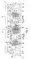
- the embodiments of the FIGS. 1 to 4 are equipped with only one linear drive 16, the embodiment of the FIG. 5 contains two linear drives 16.
- the linear drive 16 Depending on the design of the linear drive 16, electrical energy or fluid power is used as the driving force.
- the linear drive 16 according to FIGS. 1 and 2 is electrically operated. It can be seen a flanged to the first end cap 4 electric drive motor 17th
- the base structure 3 is composed of a plurality of side by side and joined together to form a rigid unit profile parts of different types together. These profile parts are produced individually and then put together to form the base structure and firmly connected by suitable fastening measures. It will be in the Usually act to a permanent attachment, although in principle a detachable attachment would be conceivable. In any case, the base structure 3 is composed of originally separate profile parts, which are joined together only later, during assembly of the base structure 3, to form a rigid composite.
- the profile parts contained in the basic structure 3 of the various embodiments of the linear drive device 1 are named differently. These are two guide profile parts 18 and at least one housing profile part 19 and, optionally, at least one widening profile part 20. All these profile parts 18, 19, 20 have a linear extension and are aligned parallel to the longitudinal axis 6. Conveniently, they all have the same length.
- the various profile parts 18, 19, 20 are produced in particular by extrusion. This makes it possible to realize a constant cross-sectional shape that is continuous over the entire length. In addition, axially continuous cavities 23 can be easily formed therein to save material and to keep the weight low. It is also possible, as shown in the guide profile parts 18, on the outer surface of one or more longitudinal mounting grooves 24 form, which are useful to releasably secure the linear drive device 1 to a support structure or other linear drive device.
- an intermediate structure 25, designated overall by reference numeral 25, is arranged which unites the at least one housing profile part 19 and, if present, the at least one widening profile part 20 and which acts as a link between the two guide profile parts 18, to connect these rigidly together.
- each guide profile part 18 carries at least one and preferably exactly one in the axial direction of the longitudinal axis 6, preferably over the entire length of the guide profile part 18, extending guide rail 26, with the carriage 13 is in each case in guide engagement.
- the guide rails 26 are firmly fixed to the guide profile parts 18, for example by being held in a retaining groove 27 formed on the outer circumference of the guide profile part 18.
- the guide rails 26 are separate components with respect to the guide profile parts 18, but they could also be formed in one piece with the associated guide profile part 18.
- the two guide rails 26 are expediently arranged on the same side of the base structure 3. In the exemplary embodiment, they are located at one of the two large main surfaces 28 of the base structure 3 which are parallel to the main expansion plane 7 and on which the carriage 13 is also arranged.
- the preferably substantially plate-shaped carriage 13 bridges the transverse spacing or intermediate space between the two guide profile parts 18, wherein in the axial direction of the transverse axis 12 at least partially Overlap with two guide profile parts 18 results.
- the carriage 13 engages in particular over the two guide rails 26, with which it is slidably engaged for carrying out the linear movement 14.
- the carriage 13 can be equipped with suitable sliding guide means or rolling guide means 29.
- the guide profile parts 18 and the at least one housing profile part 19 are arranged together in the main expansion plane 7. It is provided in particular that the at least one housing profile part 19 is accommodated exclusively in the intermediate region between the two guide profile parts 18 and does not protrude beyond these in the axial direction of the vertical axis 8.
- the housing profile part 19 has one or more axially continuous hollow chambers 32, in which at least components of linear drive means 33 are housed, which belong to a linear drive 16 or form this.
- the linear drive means 33 contain at least one coupling device 34, via which they are in mechanical or, if necessary, contactless magnetic contact with the carriage 13 in drive connection.
- a mechanical coupling is provided, wherein the coupling device 34 protrudes through a slot in the wall of the housing profile part 19 in order to engage the underside of the carriage 13 facing the base structure 3.
- the linear drive means 33 arranged in the single housing profile part 19 are designed as toothed belt drive means 33a. They contain a toothed belt, which rotates about in the two end caps 4, 5 rotatably mounted, not shown in the drawing gears, of which which is arranged in the first end cover 4 coupled to the drive motor 17. With appropriate control of the drive motor 17 of the toothed belt runs around in one or the other direction and takes in this case the running along the guide rails 26 carriage 13 in one or the other direction.
- the linear drive means 33 are in turn formed as a toothed belt drive means 33a, while they are formed in the right-hand housing profile part 19 of fluid-activatable drive means 33b.
- the latter means that they have a sealingly guided under sealing in the preferably cylindrical hollow chamber 32 pistons, which is acted upon axially from both sides via at least one of the cover cover 4.5 formed fluid channels with a drive fluid to move it linearly.
- the coupling device 34 acting on it passes through a longitudinal slot in the wall of the housing profile part 19 and engages the carriage 13.
- the thus defined linear drive 16 is thus of the type of a so-called slot cylinder, while in the other case, the design of a toothed belt linear drive is present.
- the linear drive means 33 for the realization of other types of linear drives 16 may also be designed differently.
- the piston of the fluid-activatable drive means 33b could also be drivingly coupled to the carriage 13 without contact via a magnetic device.
- an electrically operated linear drive 16 shows the FIG. 3
- an alternative with spindle drive means 33c in which in the cavity 32 an electrically rotatable threaded spindle is arranged, on which a connected to the coupling device 34 nut sits axially displaced upon rotation of the threaded spindle.
- linear drive means 33 By using appropriately adapted housing profile parts 19 and linear drive means 33, other types of linear drives can be realized, which in FIG. 3 indicated by a question mark.
- the linear drive means 33 could be designed as a linear drive motor drive means, the components of a commonly referred to as a linear motor electrodynamic linear direct drive are executed.
- housing profile part 19 directly forms the housing of the associated linear drive 16.
- a linear drive including its housing is accommodated in the housing profile part 19, so that the housing profile part 19 acts quasi as an outer housing.
- housing profile part 19 with a longitudinally continuous hollow chamber 32 into which a function-ready, fluid-actuated or electrically actuated linear drive is then inserted.
- the variant shown in the exemplary embodiments is preferred in which the housing profile part 19 directly accommodates the movable components of the linear drive means 33 without an additional housing being interposed.
- the at least one housing profile part 19 as in addition to the two guide profile parts 18 existing, independent component in the Basic structure 3 is incorporated. It forms a supporting component of the intermediate structure 25 extending parallel to the latter between the two guide profile parts 18.
- the two outer guide profile parts 18 are fastened to one another without direct connection with the interposition of at least one housing profile part 19 by means of the intermediate structure 25.
- the two guide profile parts 18 advantageously have an identical cross-sectional shape and are only arranged in mirror image. They can therefore be manufactured with the same tool, so that tolerance deviations play no role.
- FIG. 3 illustrated by a matrix, the possibilities of a very variable production of differently equipped linear drive devices 1 based on a modular system 35.
- the modular system 35 contains in any number, the two guide profile parts 18 and any number for realizing different types of linear drives 16 suitable different housing profile parts 19. From this can then be the one in the right half of the picture FIG. 3 exemplarily illustrated linear drive devices 1 are generated, which differ from each other by cross-sectionally shaped housing profile parts 19.
- the guide rails 26 and the carriage 13 are indicated only in the above-illustrated linear drive device 1.
- the intermediate structure 25 is composed of only a single housing profile part 19 together.
- This single housing profile part 19 is fastened to its two longitudinal sides oriented in the direction of the transverse axis 12 directly on the guide profile part 18 located there.
- the base structure 3 is therefore composed of a profile sub-chain consisting of two guide profile parts 18 and a housing profile part 19 arranged therebetween.
- the intermediate structure 25 additionally comprises several widening profile parts 20 between the housing profile part 19 and each guide profile part 18 are two independent, transversely to the main expansion plane. 7 and thus incorporated in the direction of the vertical axis 8 at a distance opposite widening profile parts 20, which in particular have an identical cross-sectional configuration. They are exemplarily plate-shaped, wherein they are attached with its one longitudinal edge portion on the housing profile part 19 and with its opposite longitudinal edge portion of the associated guide profile part 18.
- the linear drive device 1 can be optimally designed with respect to the compensatable torque loads.
- the widening profile parts 20 arranged on both sides of the housing profile part 19 may have a different width in the direction of the transverse axis 12. As a result, a different distance between the housing profile part 19 and the two guide profile parts 18 can be realized for special applications.
- At least one widening profile part 20 between only one of the guide profile parts 18 and the housing profile part 19 and to provide a direct fastening between the housing profile part 19 and the other guide profile part 18.
- the intermediate structure 25 can also have a plurality of housing profile parts 19 arranged side by side in parallel alignment alongside one another.
- Both housing profile parts 19 are fastened directly to the guide profile part 18 opposite here in the region of their longitudinal side facing away from the respective other housing profile part 19.
- the attachment between the itself two housing profile parts 19 is indirectly via in turn a pair comparable to FIG. 4 incorporated widening profile parts 20.
- the illustrated modular system 35 mentions that this modular system 35 can naturally also have a suitable number of widening profile parts 20. These widening profile parts 20 may have partially different cross-sectional shapes and in particular width dimensions to increase the variability. By combining with the other components, linear drive devices 1 can be realized in this way, which differ in their width and also in the placement or number of housing profile parts 19 from each other.
- FIG. 5 shows not only identically formed housing profile parts 19 can be integrated into one and the same intermediate structure 25, but also differently shaped. These can then be equipped with different types of linear drive means 33 to obtain different types of linear drives 16. This makes it possible to realize hybrid linear drive devices, which combine different drive concepts in order to obtain more variable drive possibilities for the carriage 13.
- the measures taken for the mutual attachment of immediately adjacent profile parts 18, 19, 20 measures include in all embodiments of the profile parts 18, 19, 20 formed hook structures 36 which extend in the longitudinal direction of the respective profile part 18, 19, 20 preferably over its entire length and the engage with each other such that the interlocked profile parts 18, 19, 20 are supported both in the axial direction of the transverse axis 12 and in the axial direction of the vertical axis 8 to each other and thereby a positional fixation takes place.
- the hook structures 36 are expediently designed as extensions which are L-shaped in cross section, with a first L-leg 37 protruding from a core component 39, 19, 20 in the axial direction of the transverse axis 12 and a second L protruding therefrom in the axial direction of the vertical axis 8 -Skeleton 38.
- the mutual second L-leg 38 engage behind the specification of the relative position in the direction of the transverse axis 12, and it supports each second L-leg 38 with its end face on the side surface of the first L-leg 37 of the other hook structure 36 in order to fix the relative position in the direction of the vertical axis 8.
- each guide profile part 18 and each housing profile part 19 has two hook structures 36 arranged at a spacing from one another in the direction of the vertical axis 8 for fixing to the respective adjacent profile part, so that each of these profile parts 18, 19 by means of two hook structures 36 is fixable.
- the plate-shaped in the embodiment, flat shape having widening profile parts 20 contain only a single hook structure 36 due to their low height for fixing to each adjacent profile part.
- the profile parts 18, 19, 20 can be inserted into one another in the axial direction of the longitudinal axis 6. With a corresponding configuration of the hook structures 36 pivoting from one longitudinal side is also possible.
- the profile parts 18, 19, 20 are designed so that they define in the interconnected state in the joint areas one or more longitudinally extending channel-like cavities 42, which are foamed with a mounting foam 43, which is usually made of polyurethane-based.
- the hardening during curing mounting foam 43 exerts on the cavity 42 limiting profile parts 18, 19, 20 a compressive force, which ensures that the hook structures 36 are firmly clamped together.
- the mounting foam 43 adheres to the cavity 42 bounding surfaces of the profile parts 18, 19, 20 and thereby also ensures a cohesive connection. Overall, a very rigid and inherently rigid base structure 3 is thereby obtained.
- Adjacent profile parts 18, 19, 20 can be welded together, for example, as in FIG. 2 dash-dot is indicated by a weld 44. Also an adhesive bond by applying an adhesive 45, as also in FIG. 2 indicated, would be conceivable. Furthermore, one would also be in FIG. 2 indicated screw 46 possible, which could also be realized a detachable connection.
- the different types of fastening can also be combined. Furthermore, it is possible to dispense with the interlocking hook structures 36 if an exact alignment of the profile parts 18, 19, 20 to be joined together is ensured during assembly of the base structure 3 by other measures.
- the components of the base structure 3 during assembly are expediently placed on a flat surface. If the guide profile parts 18 originate from the same tool, it is possible to dispense with machining after finishing without any disadvantages in terms of accuracy.
- the various profile parts 18, 19, 20 are expediently made of aluminum material.
- the entire device can also be used without linear drive means 33 as a drive-free slide device, the slide 13 being precisely supported and guided by the base structure 3.
- base structure 3 does not consist of a single profile part, but is divided into a plurality in cross-section smaller profile parts, also basic structures 3 can be very precisely finished with a very large overall cross-section.
- the production is relatively inexpensive, because in the case of extrusion molding can be used on pressing plants of smaller sizes.
Landscapes
- Engineering & Computer Science (AREA)
- Physics & Mathematics (AREA)
- Fluid Mechanics (AREA)
- Mechanical Engineering (AREA)
- General Engineering & Computer Science (AREA)
- Chemical & Material Sciences (AREA)
- Analytical Chemistry (AREA)
- Bearings For Parts Moving Linearly (AREA)
Priority Applications (1)
| Application Number | Priority Date | Filing Date | Title |
|---|---|---|---|
| EP07022805A EP2063132A1 (fr) | 2007-11-24 | 2007-11-24 | Dispositif d'entraînement linéaire |
Applications Claiming Priority (1)
| Application Number | Priority Date | Filing Date | Title |
|---|---|---|---|
| EP07022805A EP2063132A1 (fr) | 2007-11-24 | 2007-11-24 | Dispositif d'entraînement linéaire |
Publications (1)
| Publication Number | Publication Date |
|---|---|
| EP2063132A1 true EP2063132A1 (fr) | 2009-05-27 |
Family
ID=39323880
Family Applications (1)
| Application Number | Title | Priority Date | Filing Date |
|---|---|---|---|
| EP07022805A Withdrawn EP2063132A1 (fr) | 2007-11-24 | 2007-11-24 | Dispositif d'entraînement linéaire |
Country Status (1)
| Country | Link |
|---|---|
| EP (1) | EP2063132A1 (fr) |
Cited By (2)
| Publication number | Priority date | Publication date | Assignee | Title |
|---|---|---|---|---|
| US20160265563A1 (en) * | 2013-12-24 | 2016-09-15 | Festo Ag & Co. Kg | Linear Drive and Method for its Manufacture |
| EP3572528A1 (fr) * | 2010-09-24 | 2019-11-27 | The Board of Trustees of the Leland Stanford Junior University | Capture directe, amplification et séquençage d'adn cible à l'aide d'amorces immobilisées |
Citations (4)
| Publication number | Priority date | Publication date | Assignee | Title |
|---|---|---|---|---|
| EP0294350A1 (fr) * | 1987-06-03 | 1988-12-07 | Linjär Transportteknik I Stockholm Ab | Moteur linéaire |
| EP1589235A1 (fr) * | 2003-01-28 | 2005-10-26 | Koganei Corporation | Corps sous forme d'ensemble reuni, connecteur et unite verin hydraulique |
| DE202006013135U1 (de) | 2006-08-26 | 2006-11-02 | Festo Ag & Co. | Linearantriebseinrichtung mit Schwerlastführungsmitteln |
| DE19840876B4 (de) | 1997-09-24 | 2007-08-02 | Smc K.K. | Stangenloser Zylinder |
-
2007
- 2007-11-24 EP EP07022805A patent/EP2063132A1/fr not_active Withdrawn
Patent Citations (4)
| Publication number | Priority date | Publication date | Assignee | Title |
|---|---|---|---|---|
| EP0294350A1 (fr) * | 1987-06-03 | 1988-12-07 | Linjär Transportteknik I Stockholm Ab | Moteur linéaire |
| DE19840876B4 (de) | 1997-09-24 | 2007-08-02 | Smc K.K. | Stangenloser Zylinder |
| EP1589235A1 (fr) * | 2003-01-28 | 2005-10-26 | Koganei Corporation | Corps sous forme d'ensemble reuni, connecteur et unite verin hydraulique |
| DE202006013135U1 (de) | 2006-08-26 | 2006-11-02 | Festo Ag & Co. | Linearantriebseinrichtung mit Schwerlastführungsmitteln |
Cited By (2)
| Publication number | Priority date | Publication date | Assignee | Title |
|---|---|---|---|---|
| EP3572528A1 (fr) * | 2010-09-24 | 2019-11-27 | The Board of Trustees of the Leland Stanford Junior University | Capture directe, amplification et séquençage d'adn cible à l'aide d'amorces immobilisées |
| US20160265563A1 (en) * | 2013-12-24 | 2016-09-15 | Festo Ag & Co. Kg | Linear Drive and Method for its Manufacture |
Similar Documents
| Publication | Publication Date | Title |
|---|---|---|
| DE3627169C2 (de) | Lineare Wälzkörperführung | |
| EP0367196B1 (fr) | Unité de guidage et d'entraînement linéaire | |
| DE10229385B4 (de) | Einrichtung zur Befestigung eines Rückhaltesystems eines Verkehrs- oder Transportmittels | |
| DE19532759B4 (de) | Linearführungseinheit | |
| DE10115943A1 (de) | Antriebsvorrichtung | |
| DE112007001185B4 (de) | Einstellbarer Linearschlitten und Verfahren zum Aufbau | |
| WO2009039895A1 (fr) | Transmission par clavettes avec logement d'élément de translation | |
| DE3227902C2 (de) | Linearkugellagereinheit | |
| EP2887513B1 (fr) | Système de moteur linéaire et machine-outil dotée d'un système de moteur linéaire | |
| DE2910373C2 (de) | Antriebsvorrichtung zum spielfreien Umwandeln einer Drehbewegung in eine Linearbewegung | |
| EP2717826B1 (fr) | Support pour patients | |
| EP1892423B1 (fr) | Dispositif d'entraînement linéaire doté de moyens de guidage pour charges lourdes | |
| DE3431462C2 (fr) | ||
| DE3502868A1 (de) | Maschinentisch in modulbauweise fuer fertigungseinrichtungen | |
| AT505426B1 (de) | Verfahren zur herstellung eines trägers und träger | |
| EP0921899A1 (fr) | Chassis de guidage | |
| EP0918174B1 (fr) | Actionneur linéaire à entraínement motorisé | |
| EP2329944B1 (fr) | Presse destinée à produire une force de pression pour le traitement d'une pièce | |
| EP2063132A1 (fr) | Dispositif d'entraînement linéaire | |
| EP1612436B1 (fr) | Guide linéaire avec rail profilé | |
| DE102010052804A1 (de) | Linearführungseinrichtung | |
| DE102007002152B4 (de) | Linearantrieb | |
| DE2729938C3 (de) | Doppelbandpresse zum Herstellen von Preßplatten | |
| DE19934754B4 (de) | Führungsschienenbaugruppe, insbesondere für eine Linearführungseinrichtung | |
| DE4124157C2 (de) | Modulplatte, Träger o. dgl. Element zur Verwendung bei Maschinenaufbauten |
Legal Events
| Date | Code | Title | Description |
|---|---|---|---|
| PUAI | Public reference made under article 153(3) epc to a published international application that has entered the european phase |
Free format text: ORIGINAL CODE: 0009012 |
|
| AK | Designated contracting states |
Kind code of ref document: A1 Designated state(s): AT BE BG CH CY CZ DE DK EE ES FI FR GB GR HU IE IS IT LI LT LU LV MC MT NL PL PT RO SE SI SK TR |
|
| AX | Request for extension of the european patent |
Extension state: AL BA HR MK RS |
|
| AKX | Designation fees paid | ||
| STAA | Information on the status of an ep patent application or granted ep patent |
Free format text: STATUS: THE APPLICATION IS DEEMED TO BE WITHDRAWN |
|
| 18D | Application deemed to be withdrawn |
Effective date: 20091128 |
|
| REG | Reference to a national code |
Ref country code: DE Ref legal event code: 8566 |