EP1888439B1 - Vorrichtung und verfahren zum verbinden der enden zweier flachliegender schlauchbahnen - Google Patents
Vorrichtung und verfahren zum verbinden der enden zweier flachliegender schlauchbahnen Download PDFInfo
- Publication number
- EP1888439B1 EP1888439B1 EP06753387A EP06753387A EP1888439B1 EP 1888439 B1 EP1888439 B1 EP 1888439B1 EP 06753387 A EP06753387 A EP 06753387A EP 06753387 A EP06753387 A EP 06753387A EP 1888439 B1 EP1888439 B1 EP 1888439B1
- Authority
- EP
- European Patent Office
- Prior art keywords
- tube
- web
- webs
- wall
- tubular
- Prior art date
- Legal status (The legal status is an assumption and is not a legal conclusion. Google has not performed a legal analysis and makes no representation as to the accuracy of the status listed.)
- Expired - Lifetime
Links
Images


Classifications
-
- B—PERFORMING OPERATIONS; TRANSPORTING
- B29—WORKING OF PLASTICS; WORKING OF SUBSTANCES IN A PLASTIC STATE IN GENERAL
- B29C—SHAPING OR JOINING OF PLASTICS; SHAPING OF MATERIAL IN A PLASTIC STATE, NOT OTHERWISE PROVIDED FOR; AFTER-TREATMENT OF THE SHAPED PRODUCTS, e.g. REPAIRING
- B29C65/00—Joining or sealing of preformed parts, e.g. welding of plastics materials; Apparatus therefor
- B29C65/02—Joining or sealing of preformed parts, e.g. welding of plastics materials; Apparatus therefor by heating, with or without pressure
- B29C65/18—Joining or sealing of preformed parts, e.g. welding of plastics materials; Apparatus therefor by heating, with or without pressure using heated tools
-
- B—PERFORMING OPERATIONS; TRANSPORTING
- B29—WORKING OF PLASTICS; WORKING OF SUBSTANCES IN A PLASTIC STATE IN GENERAL
- B29C—SHAPING OR JOINING OF PLASTICS; SHAPING OF MATERIAL IN A PLASTIC STATE, NOT OTHERWISE PROVIDED FOR; AFTER-TREATMENT OF THE SHAPED PRODUCTS, e.g. REPAIRING
- B29C65/00—Joining or sealing of preformed parts, e.g. welding of plastics materials; Apparatus therefor
- B29C65/78—Means for handling the parts to be joined, e.g. for making containers or hollow articles, e.g. means for handling sheets, plates, web-like materials, tubular articles, hollow articles or elements to be joined therewith; Means for discharging the joined articles from the joining apparatus
- B29C65/7841—Holding or clamping means for handling purposes
-
- B—PERFORMING OPERATIONS; TRANSPORTING
- B29—WORKING OF PLASTICS; WORKING OF SUBSTANCES IN A PLASTIC STATE IN GENERAL
- B29C—SHAPING OR JOINING OF PLASTICS; SHAPING OF MATERIAL IN A PLASTIC STATE, NOT OTHERWISE PROVIDED FOR; AFTER-TREATMENT OF THE SHAPED PRODUCTS, e.g. REPAIRING
- B29C66/00—General aspects of processes or apparatus for joining preformed parts
- B29C66/004—Preventing sticking together, e.g. of some areas of the parts to be joined
-
- B—PERFORMING OPERATIONS; TRANSPORTING
- B29—WORKING OF PLASTICS; WORKING OF SUBSTANCES IN A PLASTIC STATE IN GENERAL
- B29C—SHAPING OR JOINING OF PLASTICS; SHAPING OF MATERIAL IN A PLASTIC STATE, NOT OTHERWISE PROVIDED FOR; AFTER-TREATMENT OF THE SHAPED PRODUCTS, e.g. REPAIRING
- B29C66/00—General aspects of processes or apparatus for joining preformed parts
- B29C66/01—General aspects dealing with the joint area or with the area to be joined
- B29C66/02—Preparation of the material, in the area to be joined, prior to joining or welding
- B29C66/022—Mechanical pre-treatments, e.g. reshaping
- B29C66/0224—Mechanical pre-treatments, e.g. reshaping with removal of material
- B29C66/02241—Cutting, e.g. by using waterjets, or sawing
-
- B—PERFORMING OPERATIONS; TRANSPORTING
- B29—WORKING OF PLASTICS; WORKING OF SUBSTANCES IN A PLASTIC STATE IN GENERAL
- B29C—SHAPING OR JOINING OF PLASTICS; SHAPING OF MATERIAL IN A PLASTIC STATE, NOT OTHERWISE PROVIDED FOR; AFTER-TREATMENT OF THE SHAPED PRODUCTS, e.g. REPAIRING
- B29C66/00—General aspects of processes or apparatus for joining preformed parts
- B29C66/01—General aspects dealing with the joint area or with the area to be joined
- B29C66/05—Particular design of joint configurations
- B29C66/10—Particular design of joint configurations particular design of the joint cross-sections
- B29C66/11—Joint cross-sections comprising a single joint-segment, i.e. one of the parts to be joined comprising a single joint-segment in the joint cross-section
- B29C66/112—Single lapped joints
- B29C66/1122—Single lap to lap joints, i.e. overlap joints
-
- B—PERFORMING OPERATIONS; TRANSPORTING
- B29—WORKING OF PLASTICS; WORKING OF SUBSTANCES IN A PLASTIC STATE IN GENERAL
- B29C—SHAPING OR JOINING OF PLASTICS; SHAPING OF MATERIAL IN A PLASTIC STATE, NOT OTHERWISE PROVIDED FOR; AFTER-TREATMENT OF THE SHAPED PRODUCTS, e.g. REPAIRING
- B29C66/00—General aspects of processes or apparatus for joining preformed parts
- B29C66/01—General aspects dealing with the joint area or with the area to be joined
- B29C66/348—Avoiding melting or weakening of the zone directly next to the joint area, e.g. by cooling
-
- B—PERFORMING OPERATIONS; TRANSPORTING
- B29—WORKING OF PLASTICS; WORKING OF SUBSTANCES IN A PLASTIC STATE IN GENERAL
- B29C—SHAPING OR JOINING OF PLASTICS; SHAPING OF MATERIAL IN A PLASTIC STATE, NOT OTHERWISE PROVIDED FOR; AFTER-TREATMENT OF THE SHAPED PRODUCTS, e.g. REPAIRING
- B29C66/00—General aspects of processes or apparatus for joining preformed parts
- B29C66/50—General aspects of joining tubular articles; General aspects of joining long products, i.e. bars or profiled elements; General aspects of joining single elements to tubular articles, hollow articles or bars; General aspects of joining several hollow-preforms to form hollow or tubular articles
- B29C66/51—Joining tubular articles, profiled elements or bars; Joining single elements to tubular articles, hollow articles or bars; Joining several hollow-preforms to form hollow or tubular articles
- B29C66/52—Joining tubular articles, bars or profiled elements
- B29C66/522—Joining tubular articles
- B29C66/5221—Joining tubular articles for forming coaxial connections, i.e. the tubular articles to be joined forming a zero angle relative to each other
-
- B—PERFORMING OPERATIONS; TRANSPORTING
- B29—WORKING OF PLASTICS; WORKING OF SUBSTANCES IN A PLASTIC STATE IN GENERAL
- B29C—SHAPING OR JOINING OF PLASTICS; SHAPING OF MATERIAL IN A PLASTIC STATE, NOT OTHERWISE PROVIDED FOR; AFTER-TREATMENT OF THE SHAPED PRODUCTS, e.g. REPAIRING
- B29C66/00—General aspects of processes or apparatus for joining preformed parts
- B29C66/80—General aspects of machine operations or constructions and parts thereof
- B29C66/82—Pressure application arrangements, e.g. transmission or actuating mechanisms for joining tools or clamps
- B29C66/822—Transmission mechanisms
- B29C66/8221—Scissor or lever mechanisms, i.e. involving a pivot point
-
- B—PERFORMING OPERATIONS; TRANSPORTING
- B29—WORKING OF PLASTICS; WORKING OF SUBSTANCES IN A PLASTIC STATE IN GENERAL
- B29C—SHAPING OR JOINING OF PLASTICS; SHAPING OF MATERIAL IN A PLASTIC STATE, NOT OTHERWISE PROVIDED FOR; AFTER-TREATMENT OF THE SHAPED PRODUCTS, e.g. REPAIRING
- B29C66/00—General aspects of processes or apparatus for joining preformed parts
- B29C66/80—General aspects of machine operations or constructions and parts thereof
- B29C66/83—General aspects of machine operations or constructions and parts thereof characterised by the movement of the joining or pressing tools
- B29C66/832—Reciprocating joining or pressing tools
- B29C66/8324—Joining or pressing tools pivoting around one axis
- B29C66/83241—Joining or pressing tools pivoting around one axis cooperating pivoting tools
-
- B—PERFORMING OPERATIONS; TRANSPORTING
- B29—WORKING OF PLASTICS; WORKING OF SUBSTANCES IN A PLASTIC STATE IN GENERAL
- B29C—SHAPING OR JOINING OF PLASTICS; SHAPING OF MATERIAL IN A PLASTIC STATE, NOT OTHERWISE PROVIDED FOR; AFTER-TREATMENT OF THE SHAPED PRODUCTS, e.g. REPAIRING
- B29C66/00—General aspects of processes or apparatus for joining preformed parts
- B29C66/80—General aspects of machine operations or constructions and parts thereof
- B29C66/84—Specific machine types or machines suitable for specific applications
- B29C66/853—Machines for changing web rolls or filaments, e.g. for joining a replacement web to an expiring web
-
- B—PERFORMING OPERATIONS; TRANSPORTING
- B65—CONVEYING; PACKING; STORING; HANDLING THIN OR FILAMENTARY MATERIAL
- B65H—HANDLING THIN OR FILAMENTARY MATERIAL, e.g. SHEETS, WEBS, CABLES
- B65H19/00—Changing the web roll
- B65H19/10—Changing the web roll in unwinding mechanisms or in connection with unwinding operations
- B65H19/14—Accumulating surplus web for advancing to machine while changing the web roll
-
- B—PERFORMING OPERATIONS; TRANSPORTING
- B65—CONVEYING; PACKING; STORING; HANDLING THIN OR FILAMENTARY MATERIAL
- B65H—HANDLING THIN OR FILAMENTARY MATERIAL, e.g. SHEETS, WEBS, CABLES
- B65H19/00—Changing the web roll
- B65H19/10—Changing the web roll in unwinding mechanisms or in connection with unwinding operations
- B65H19/18—Attaching, e.g. pasting, the replacement web to the expiring web
- B65H19/1842—Attaching, e.g. pasting, the replacement web to the expiring web standing splicing, i.e. the expiring web being stationary during splicing contact
- B65H19/1852—Attaching, e.g. pasting, the replacement web to the expiring web standing splicing, i.e. the expiring web being stationary during splicing contact taking place at a distance from the replacement roll
-
- B—PERFORMING OPERATIONS; TRANSPORTING
- B29—WORKING OF PLASTICS; WORKING OF SUBSTANCES IN A PLASTIC STATE IN GENERAL
- B29C—SHAPING OR JOINING OF PLASTICS; SHAPING OF MATERIAL IN A PLASTIC STATE, NOT OTHERWISE PROVIDED FOR; AFTER-TREATMENT OF THE SHAPED PRODUCTS, e.g. REPAIRING
- B29C2793/00—Shaping techniques involving a cutting or machining operation
- B29C2793/0081—Shaping techniques involving a cutting or machining operation before shaping
-
- B—PERFORMING OPERATIONS; TRANSPORTING
- B29—WORKING OF PLASTICS; WORKING OF SUBSTANCES IN A PLASTIC STATE IN GENERAL
- B29C—SHAPING OR JOINING OF PLASTICS; SHAPING OF MATERIAL IN A PLASTIC STATE, NOT OTHERWISE PROVIDED FOR; AFTER-TREATMENT OF THE SHAPED PRODUCTS, e.g. REPAIRING
- B29C65/00—Joining or sealing of preformed parts, e.g. welding of plastics materials; Apparatus therefor
- B29C65/78—Means for handling the parts to be joined, e.g. for making containers or hollow articles, e.g. means for handling sheets, plates, web-like materials, tubular articles, hollow articles or elements to be joined therewith; Means for discharging the joined articles from the joining apparatus
- B29C65/7841—Holding or clamping means for handling purposes
- B29C65/7847—Holding or clamping means for handling purposes using vacuum to hold at least one of the parts to be joined
-
- B—PERFORMING OPERATIONS; TRANSPORTING
- B29—WORKING OF PLASTICS; WORKING OF SUBSTANCES IN A PLASTIC STATE IN GENERAL
- B29L—INDEXING SCHEME ASSOCIATED WITH SUBCLASS B29C, RELATING TO PARTICULAR ARTICLES
- B29L2023/00—Tubular articles
- B29L2023/001—Tubular films, sleeves
-
- B—PERFORMING OPERATIONS; TRANSPORTING
- B65—CONVEYING; PACKING; STORING; HANDLING THIN OR FILAMENTARY MATERIAL
- B65H—HANDLING THIN OR FILAMENTARY MATERIAL, e.g. SHEETS, WEBS, CABLES
- B65H2301/00—Handling processes for sheets or webs
- B65H2301/40—Type of handling process
- B65H2301/46—Splicing
- B65H2301/4606—Preparing leading edge for splicing
-
- B—PERFORMING OPERATIONS; TRANSPORTING
- B65—CONVEYING; PACKING; STORING; HANDLING THIN OR FILAMENTARY MATERIAL
- B65H—HANDLING THIN OR FILAMENTARY MATERIAL, e.g. SHEETS, WEBS, CABLES
- B65H2301/00—Handling processes for sheets or webs
- B65H2301/40—Type of handling process
- B65H2301/46—Splicing
- B65H2301/462—Form of splice
- B65H2301/4621—Overlapping article or web portions
-
- B—PERFORMING OPERATIONS; TRANSPORTING
- B65—CONVEYING; PACKING; STORING; HANDLING THIN OR FILAMENTARY MATERIAL
- B65H—HANDLING THIN OR FILAMENTARY MATERIAL, e.g. SHEETS, WEBS, CABLES
- B65H2511/00—Dimensions; Position; Numbers; Identification; Occurrences
- B65H2511/20—Location in space
- B65H2511/22—Distance
-
- B—PERFORMING OPERATIONS; TRANSPORTING
- B65—CONVEYING; PACKING; STORING; HANDLING THIN OR FILAMENTARY MATERIAL
- B65H—HANDLING THIN OR FILAMENTARY MATERIAL, e.g. SHEETS, WEBS, CABLES
- B65H2701/00—Handled material; Storage means
- B65H2701/30—Handled filamentary material
- B65H2701/33—Hollow or hose-like material
- B65H2701/332—Flattened hoses
Definitions
- the invention relates to a device and a method for connecting the ends of two flat-lying tubular webs.
- Apparatus for processing of hose material usually deduct this from winding on which the material to be processed is wound in the form of tubular webs.
- Such devices for processing the tube webs are usually continuously, but occasionally also cyclically fed.
- the beginning of a new tube web into the processing device after processing all tubing that provides the winding, usually the end of the first tube web with the beginning of the new tube web, which also serves as a wrap Is made available.
- the operation of the apparatus for processing tubing must not be interrupted or only for a negligible time for the purpose of changing the roll.
- Such a device is known from DE 102 40 644 A1 known.
- connection of tubular webs can be done by any type of connection, for example by gluing. If the tubes are made of plastic, welding is usually the preferred method of connection.
- FFS Form, Fill and Seal
- Such a device is for example in the patent DE 199 36 660 C1 the applicant described.
- a special type of tubular webs are those with gussets. Such gusseted tubes are preferably used in said FFS machines. When connecting the ends of two tubular webs, however, it is important that after joining the two tubular webs, the gussets are continuous. This is not guaranteed if, for example, both tube webs are connected lying on each other. Again, in other applications, it is important that the interior of the hose, even in the region of the joint, is continuous. Thus, in order to be able to easily use the connection point of the ends of two tubular webs in devices for processing such tubular webs, these tubular webs must be connected in a special way.
- the EP 1 304 214 A1 to provide one end with the inner edges of the gusseted cuts and then insert the other end into the split area in such a way that the two walls with one layer of each gusset of the end portion of a tubular film enclose the other end between them , In the gussets of the enclosed other end portion separating layers are inserted or inserted and the ends then connected by a transverse weld. In this way it is also possible to ensure continuous gussets over the joints.
- the patent application EP 1 201 585 A1 shows a method for joining the ends of two tubular webs without gussets.
- the tube webs connected according to the method shown there are also continuous in the region of the connection point, so that the operation of the tube web-processing machine does not have to be interrupted for a reel change in order to thread a new tubular web into the machine.
- the in the EP 1 201 585 A1 shown device for implementation of the method comprises a bearing unit with a plurality of coils or rollers, which are arranged side by side. The ends of the wound on these coils tubular webs are cut in the region of their side edges, so that the upper and the lower walls of these tubular webs are separated from each other.
- a belt which extends in a direction transverse to the longitudinal axes of the tubular webs and is movable in this direction.
- This belt is not endless circulating, but interrupted in the area in which the tubular web that is being processed, is deducted from the corresponding winding.
- the two ends of the belt are connected by a subframe, which is designed so that only the hose path that is currently being processed is located in the interruption area of the belt. If now the beginning of a new tubular web to the end of the straight withdrawn tube web are connected, the transport of the tubular web is first interrupted for processing machine and the withdrawn tubular web cut parallel to the belt, so that the end of the tubular web the broken region of the belt bridged.
- the belt is driven until the end of the tube web has been inserted between the upper and lower wall of the end of the tube web of another coil, that the longitudinal axes of the old and the new tube web are aligned. Due to this transverse displacement of the end of the old tubular web and because of the interruption of the belt, the end of the new tubular web comes directly into contact with the end of the old tubular web. In this case, the upper wall of the end of the new tubular web on the upper wall of the end of the old tubular web comes to rest and the lower wall of the end of the new tubular web on the lower wall of the end of the old tubular web.
- tubular webs which are made of plastic, welded together by welding jaws, which are brought from above and from below to the superimposed areas of the ends of the two tubular webs.
- an internal tool is provided Divider provided. In this way, the inner continuity of the hose is maintained across the joint.
- the belt which, prior to joining the ends of the old and new tubular webs, makes a movement which is transverse to the longitudinal axes of the tubular webs.
- the belt may partially pull along the upper and lower walls, so that subsequently the walls may not rest smoothly on the outer walls of the end of the old tubular web. This can lead to a poor connection of the two ends and thus to a crack of the connection point or to further disturbances in the machine processing the tubular web.
- the devices mentioned can lead to unreliability in the connection process and poor quality connections.
- the object of the present invention is therefore to propose a device for connecting the ends of two flat tubular webs, with which the connection process is more reliable feasible and which leads to qualitatively improved connections of tubular webs.
- the upper and the lower wall of the end of the one tubular web are movable by means for guiding at least partially in the direction of the longitudinal axis of the tubular webs.
- the upper and the lower wall of the end of a tubular web are at least partially movable in the direction of the longitudinal axis of the tubular webs by the means for guiding, these walls can create smooth and flat against the walls of the other tube, so that the walls of the a tube web and the walls of the other tubular path plane-parallel to each other.
- the device is preferred designed so that the walls of the new tube web are placed on the outer walls of the terminating tubular web.
- the end of the ending tubular web can also be divided or separated into an upper and a lower wall, so that these walls can be placed on the outer walls of the following tubular web.
- the movement of the walls can be effected by guide means, which are movable in the longitudinal direction of the tubular webs.
- holding means such as grippers or suction elements can be provided which are rotatable about an axis, which then preferably transverse to the longitudinal axes of the tube webs.
- This axis is preferably located at the end of the cuts, which define an upper and a lower wall of the end of the one tubular web, so that the upper and lower walls are joined by a folding movement, which naturally also includes a movement proportion in the longitudinal direction of the tubular webs the walls of the other tubular web can be stored.
- the ends of the tubular webs are durable by means of holding means in fixed positions.
- These holding means can be configured as jaws, but also as a sucker. Further holding means are conceivable. This avoids the retreat of the other tubular web on which the walls are laid. During this time, the production process in the machine processing a tubular web is preferably stopped. However, it can also be provided a web memory, which avoids the interruption of production.
- the means for guiding comprise deflection means, which are displaceable parallel to the longitudinal axis of the tubular webs.
- deflection means which are displaceable parallel to the longitudinal axis of the tubular webs.
- Particularly cost-effective deflection means are created when these are designed as sheets or plates which limit a gap. The upper or lower wall is guided during the movement of these sheets or plates, in each case along an edge delimiting the gap, so that the walls are folded over onto the end of the other tube web.
- the sheets or plates can be designed as a component, for example a sheet-metal plate, into which a slit-forming elongated hole is made through which the tubular web runs.
- the deflection means can be designed as rollers or rollers. Depending on a roller or roller then rolls on the upper or lower wall of the end of a tubular web, so that they create the outer walls of the other tubular web without the latter being moved accidentally.
- These deflecting means may also be referred to as pressing means and remain in contact with the walls until the bonding process has ended, that is, for example, until the adhesive used has set for the preparation of the compound or until the use of plastic webs a weld or a sealed joint has been carried out. In this way it is prevented that the ends of the tube webs in a not yet loadable connection again separate from each other.
- tubular webs with side folds are preferably processed.
- the end of a tubular web is preferably cut along the inner edges of the gussets. This has the consequence that when the device after the EP 1 201 585 A1 to join the ends of the tube webs with gussets, could possibly unfold the layers of the previous gussets, thereby disturbing or even preventing the bonding process.
- the device according to the invention is therefore particularly suitable for the connection of the ends of gusseted tubes.
- Gusseted hoses which are processed in the FFS machines described above, often consist of plastic.
- the ends of plastic hoses are usually connected by a weld.
- separating means for example separating plates, are provided, which can be inserted into the side folds.
- a can also Inner tool can be provided, which also prevents the welding of the outer walls.
- the weld preferably extends transversely to the longitudinal axis of the film tubes, wherein the weld or adhesive seam may be interrupted to permit leakage of the air which may be trapped in contacting the upper and lower walls of one tubular web with the outer walls of the other web enable.
- Other joint seams, such as adhesive seams may be interrupted to allow the air outlet.
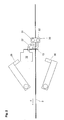
- FIGS. 1 and 2 show a device 1 according to the invention, wherein only some of the necessary components for the preparation of the connection are shown.
- Shown is a winding 2, deducted from which a tubular web 3 and in the transport direction z, which runs along the longitudinal axis 4 of the tubular web 3, a tube web-processing machine is supplied.
- the tube web 3 is guided, inter alia, between two rollers 31 and 32, which are rotatably mounted in two side plates, of which the front plate 33 seen in the direction of the viewer is shown.
- the winding 2 is based on a not shown Cart or carriage, which is displaceable transversely to the longitudinal axis 4 of the tubular web 3 in the machine frame, also not shown. On the carriage or carriage continues to support the winding 5, on which a tubular web 6 is wound.
- gussets 7 are exemplified by further lines.
- the tube web 6 is in the waiting position for the connection operation of the two ends, as in the Fig. 4 is shown.
- the leading end 26 of the tubular web 6 is cut in the region of the side edges, so that this end 26 consists of an upper wall 14 and a lower wall 15.
- the upper wall 14 and the lower wall 15 partially wrap around the rollers 16 and 17, respectively, which serve as deflecting means and which are rotatably mounted in side plates.
- the walls 14 and 15 are additionally held by jaw pairs 20, 21 and 22, 23 so that they extend substantially in a plane which is orthogonal to the longitudinal axis of the tubular web 6.
- the tubular web 6 is additionally locked by a pair of jaws 24, 25.
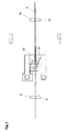
- the carriage or carriage is displaced so that the longitudinal axes of the tubular webs 3 and 6 aligned with each other.
- This situation will be in Fig. 5 shown.
- the arranged on the blade carrier 12 hook 27 and arranged on the plates 18, 19 hook 28 reach a position in which the hooks 27, 28 can engage with each other.
- the knife carrier 12 which is slidably mounted in the machine frame, in the direction of the longitudinal axis 4 of the tube web 3, for example, by the action of a pneumatic cylinder, displaced and takes the plates 18, 19 and thus the rollers 16 and 17 with.
- a metal plate can be provided with a slot, wherein the boundary edges of the slot take over the function of the rollers.
- the jaws 20, 21 and 22, 23 hold the walls 14, 15, although initially in the in the Fig. 4 However, the jaws act on the walls only with such a force that a pulling out of the walls of the jaw columns is possible.
- the displacement of the knife carrier 12 takes place until in the Fig. 6 shown operating position is reached, in which the rollers 16, 17 are still in contact with the walls 14, 15.
- dividers can be inserted during the following welding process in the gussets 7, so that their individual layers are not welded.
- the baffles remain permanently within the gussets, so that they represent additional guiding and stabilizing means when the tube web is pulled off the winding.
- welding bar 29, 30, which are mounted on pivotable arms in the machine frame, lowered onto the overlap region of the ends of the tube webs and then welded the layers of the overlap region with each other.
- welding bar 29, 30, which are mounted on pivotable arms in the machine frame, lowered onto the overlap region of the ends of the tube webs and then welded the layers of the overlap region with each other.
- the welding bars 29, 30 are pivoted back, and the knife carrier 12 is moved back together with the rollers 16, 17 back to their initial positions.
- the side plates 18, 19 can be acted upon by a spring force.
- the jaw pairs 8, 9 and 24, 25 are removed from the tubular webs, so that the machine processing the tubular webs is now supplied with the tubular web 6.
- the winding 2 can now be replaced by a new, full winding, the beginning of the wound on him tubular web in one of the in the Fig. 4 shown waiting position can be brought.
- FIG. 8 shows an alternative embodiment of a device according to the invention.
- the upper wall 14 and lower wall 15 are deflected in this case not by rollers, but at the edges of the metal strips 34 and 35, which define a gap 36 through which 36 the tubular web 6 is guided.
- the metal strips are interconnected by connecting elements, not shown, the metal strips 35, 36 and the connecting elements may be components of a one-piece metal plate.
- On the lower sheet metal strip 35 of the hook 28 is arranged. If a one-piece sheet metal plate is used, it makes sense to also integrally form the hook and sheet metal plate, wherein areas of the sheet metal plate can be formed by simply folding to hook 28.
- the edges of the sheet-metal strips 34 and 35 adjoining the gap 36 are preferably rounded in order to be able to guide the upper and lower walls 14, 15 as free of damage as possible.
Landscapes
- Engineering & Computer Science (AREA)
- Mechanical Engineering (AREA)
- Replacement Of Web Rolls (AREA)
- Lining Or Joining Of Plastics Or The Like (AREA)
- Making Paper Articles (AREA)
Priority Applications (1)
| Application Number | Priority Date | Filing Date | Title |
|---|---|---|---|
| PL06753387T PL1888439T3 (pl) | 2005-04-20 | 2006-04-04 | Urządzenie i sposób połączenia końców dwóch płasko leżących taśm rękawa |
Applications Claiming Priority (2)
| Application Number | Priority Date | Filing Date | Title |
|---|---|---|---|
| DE200510018546 DE102005018546B4 (de) | 2005-04-20 | 2005-04-20 | Vorrichtung und Verfahren zum Verbinden der Enden zweier flachliegender Schlauchbahnen |
| PCT/EP2006/003453 WO2006111332A1 (de) | 2005-04-20 | 2006-04-04 | Vorrichtung und verfahren zum verbinden der enden zweier flachliegender schlauchbahnen |
Publications (2)
| Publication Number | Publication Date |
|---|---|
| EP1888439A1 EP1888439A1 (de) | 2008-02-20 |
| EP1888439B1 true EP1888439B1 (de) | 2009-12-30 |
Family
ID=36603332
Family Applications (1)
| Application Number | Title | Priority Date | Filing Date |
|---|---|---|---|
| EP06753387A Expired - Lifetime EP1888439B1 (de) | 2005-04-20 | 2006-04-04 | Vorrichtung und verfahren zum verbinden der enden zweier flachliegender schlauchbahnen |
Country Status (8)
| Country | Link |
|---|---|
| EP (1) | EP1888439B1 (https=) |
| JP (1) | JP4964228B2 (https=) |
| CN (1) | CN101160252B (https=) |
| AT (1) | ATE453597T1 (https=) |
| DE (2) | DE102005018546B4 (https=) |
| ES (1) | ES2337605T3 (https=) |
| PL (1) | PL1888439T3 (https=) |
| WO (1) | WO2006111332A1 (https=) |
Families Citing this family (7)
| Publication number | Priority date | Publication date | Assignee | Title |
|---|---|---|---|---|
| DE102007056348A1 (de) | 2007-11-22 | 2009-05-28 | Krones Ag | Vorrichtung zum Verbinden von Kunststoffschläuchen |
| ITBO20120321A1 (it) * | 2012-06-11 | 2013-12-12 | Sorma S P A | Dispositivo e metodo per la saldatura di reti tubolari, e simili, per il confezionamento di prodotti |
| WO2018163339A1 (ja) * | 2017-03-08 | 2018-09-13 | ユニ・チャーム株式会社 | 筒状の連続シートを継ぐ方法及び装置 |
| FR3069184B1 (fr) * | 2017-07-18 | 2021-10-01 | Sleever Int | Dispositif de raccordement de gaines par encollage interne, rouleau d'adhesif et procede de raccordement correspondants |
| JP7246627B2 (ja) * | 2017-10-17 | 2023-03-28 | 近江度量衡株式会社 | 袋体セット装置 |
| DE102019122312B4 (de) * | 2019-08-20 | 2022-12-22 | Voith Patent Gmbh | Bahnhaltevorrichtung |
| DE102022209086A1 (de) * | 2022-09-01 | 2024-03-07 | Windmöller & Hölscher Kg | Verfahren zum Wechseln von Schlauchrollen |
Family Cites Families (13)
| Publication number | Priority date | Publication date | Assignee | Title |
|---|---|---|---|---|
| JPS5991822U (ja) * | 1982-12-13 | 1984-06-21 | 花王株式会社 | 原袋接続装置 |
| JPS6097797U (ja) * | 1983-12-07 | 1985-07-03 | 花王株式会社 | 原反接続装置 |
| ES2149657B1 (es) * | 1997-05-05 | 2001-05-16 | Barberan Sa | Cabezal para el cambio automatico de bobinas suministradoras de folio en continuo. |
| DE19936660C2 (de) * | 1999-05-04 | 2002-10-24 | Windmoeller & Hoelscher | Vorrichtung zum Herstellen, Befüllen und Verschließen von Säcken |
| DE10040055C2 (de) * | 2000-08-11 | 2002-10-31 | Windmoeller & Hoelscher | Abzugsvorrichtung für Schlauchbahnen aus Kunststofffolie |
| NL1016442C2 (nl) * | 2000-10-19 | 2002-04-22 | Fuji Seal Europe Bv | Werkwijze en inrichting voor het met elkaar verbinden van het einde van een platgedrukte slang uit kunststoffolie met het begin van een volgende slang. |
| FR2821431B1 (fr) * | 2001-02-28 | 2003-11-21 | Louis Lery | Reactif destine au depistage ante-morten d'atnc |
| DE10151144A1 (de) * | 2001-10-17 | 2003-04-30 | Windmoeller & Hoelscher | Verfahren zum Verbinden zweier Enden von flachliegenden und mit Seitenfalten versehenen Schlauchfolienbahnen |
| JP3966773B2 (ja) * | 2002-06-24 | 2007-08-29 | 株式会社フジシールインターナショナル | 筒状フィルム接続方法及びフィルムロール |
| DE10240644A1 (de) * | 2002-09-03 | 2004-03-11 | Brisay-Maschinen Gmbh | Vorrichtung zur Schlauchfolienankopplung |
| CN2570223Y (zh) * | 2002-09-19 | 2003-09-03 | 汕头市华鹰软包装设备总厂有限公司 | 用于卷筒材料放卷的零速接料装置 |
| AT500126B1 (de) * | 2003-11-04 | 2007-05-15 | Deininger Karl Dipl Ing | Verfahren zum wechseln von schlauchrollen, insbesondere für seitenfaltenschläuche |
| DE202004013959U1 (de) * | 2004-09-05 | 2006-01-19 | Haver & Boecker | Schlauchfolie und Vorrichtung zur Verbindung zweier Enden von Schlauchfolien |
-
2005
- 2005-04-20 DE DE200510018546 patent/DE102005018546B4/de not_active Expired - Lifetime
-
2006
- 2006-04-04 PL PL06753387T patent/PL1888439T3/pl unknown
- 2006-04-04 DE DE502006005790T patent/DE502006005790D1/de not_active Expired - Fee Related
- 2006-04-04 AT AT06753387T patent/ATE453597T1/de active
- 2006-04-04 JP JP2008506982A patent/JP4964228B2/ja not_active Expired - Lifetime
- 2006-04-04 EP EP06753387A patent/EP1888439B1/de not_active Expired - Lifetime
- 2006-04-04 CN CN200680012799XA patent/CN101160252B/zh not_active Expired - Fee Related
- 2006-04-04 WO PCT/EP2006/003453 patent/WO2006111332A1/de not_active Ceased
- 2006-04-04 ES ES06753387T patent/ES2337605T3/es not_active Expired - Lifetime
Also Published As
| Publication number | Publication date |
|---|---|
| CN101160252A (zh) | 2008-04-09 |
| DE102005018546B4 (de) | 2015-04-02 |
| JP4964228B2 (ja) | 2012-06-27 |
| DE502006005790D1 (de) | 2010-02-11 |
| PL1888439T3 (pl) | 2010-07-30 |
| DE102005018546A1 (de) | 2006-11-02 |
| CN101160252B (zh) | 2013-07-17 |
| JP2008536775A (ja) | 2008-09-11 |
| EP1888439A1 (de) | 2008-02-20 |
| ATE453597T1 (de) | 2010-01-15 |
| WO2006111332A1 (de) | 2006-10-26 |
| ES2337605T3 (es) | 2010-04-27 |
Similar Documents
| Publication | Publication Date | Title |
|---|---|---|
| DE3723601C2 (https=) | ||
| EP2391502B1 (de) | Vorrichtung zur herstellung von säcken aus schlauchförmigem material | |
| DE3723827C2 (https=) | ||
| DE3727339A1 (de) | Vorrichtung zum wechseln von auf eine vorratsrolle aufgewickelten folienbahnen | |
| DE102011080462A1 (de) | Verfahren und Vorrichtung zum Herstellen, Befüllen und Verschließen von Säcken sowie ein Sack | |
| DE10306615A1 (de) | Verfahren zur Herstellung von Säcken | |
| EP1701887B1 (de) | Verfahren zum wechseln von schlauchrollen | |
| EP0749924A1 (de) | Verfahren und Vorrichtung zum Verschweissen zweier von jeweils einer Vorratsrolle kommender Folienbahnen in einer Verpackungsmaschine | |
| DE3809125C2 (https=) | ||
| EP1888439B1 (de) | Vorrichtung und verfahren zum verbinden der enden zweier flachliegender schlauchbahnen | |
| EP0299180A2 (de) | Abwickelvorrichtung für Papier- oder Kartonbahn | |
| EP1163178A1 (de) | Vorrichtung zum verbinden von materialbahnen | |
| WO2009121542A1 (de) | Vorrichtung und verfahren zur herstellung von säcken aus schlauchstücken | |
| EP1597054B1 (de) | Schlauch sowie vorrichtung und verfahren zur herstellung desselben | |
| EP1919810A1 (de) | Verfahren und vorrichtung zur verbindung zweier materialbahnen | |
| EP1423323A1 (de) | Vorrichtung zum durchtrennen einer laufenden materialbahn und zum festlegen des nachlaufenden bahnanfangs auf einer wickelhülse | |
| EP3190057B1 (de) | Folienschlauchverpackungsmaschine | |
| EP3360806B1 (de) | Folienschlauchverpackungsmaschine | |
| EP3697709B1 (de) | Abrollstation | |
| DE19923097A1 (de) | Vorrichtung zum Verbinden von Materialbahnen | |
| AT502291B1 (de) | Verfahren und vorrichtung zur verbindung zweier materialbahnen | |
| DE4338781A1 (de) | Verfahren und Vorrichtung zur Herstellung eines Sackes oder Beutels aus thermoplastischem Kunststoff mit Traggriff | |
| DE1250731B (https=) | ||
| DE3740058A1 (de) | Verfahren und vorrichtung zum herstellen von saecken, insbesondere papiersaecken, aus einem flachgelegten schlauch | |
| DE9311290U1 (de) | Vorrichtung zum automatischen umschweissen von verpackungs-folien |
Legal Events
| Date | Code | Title | Description |
|---|---|---|---|
| PUAI | Public reference made under article 153(3) epc to a published international application that has entered the european phase |
Free format text: ORIGINAL CODE: 0009012 |
|
| 17P | Request for examination filed |
Effective date: 20071120 |
|
| AK | Designated contracting states |
Kind code of ref document: A1 Designated state(s): AT BE BG CH CY CZ DE DK EE ES FI FR GB GR HU IE IS IT LI LT LU LV MC NL PL PT RO SE SI SK TR |
|
| DAX | Request for extension of the european patent (deleted) | ||
| GRAP | Despatch of communication of intention to grant a patent |
Free format text: ORIGINAL CODE: EPIDOSNIGR1 |
|
| GRAS | Grant fee paid |
Free format text: ORIGINAL CODE: EPIDOSNIGR3 |
|
| GRAA | (expected) grant |
Free format text: ORIGINAL CODE: 0009210 |
|
| AK | Designated contracting states |
Kind code of ref document: B1 Designated state(s): AT BE BG CH CY CZ DE DK EE ES FI FR GB GR HU IE IS IT LI LT LU LV MC NL PL PT RO SE SI SK TR |
|
| REG | Reference to a national code |
Ref country code: GB Ref legal event code: FG4D Free format text: NOT ENGLISH |
|
| REG | Reference to a national code |
Ref country code: CH Ref legal event code: EP |
|
| REG | Reference to a national code |
Ref country code: IE Ref legal event code: FG4D |
|
| REF | Corresponds to: |
Ref document number: 502006005790 Country of ref document: DE Date of ref document: 20100211 Kind code of ref document: P |
|
| REG | Reference to a national code |
Ref country code: ES Ref legal event code: FG2A Ref document number: 2337605 Country of ref document: ES Kind code of ref document: T3 |
|
| PG25 | Lapsed in a contracting state [announced via postgrant information from national office to epo] |
Ref country code: SE Free format text: LAPSE BECAUSE OF FAILURE TO SUBMIT A TRANSLATION OF THE DESCRIPTION OR TO PAY THE FEE WITHIN THE PRESCRIBED TIME-LIMIT Effective date: 20091230 Ref country code: FI Free format text: LAPSE BECAUSE OF FAILURE TO SUBMIT A TRANSLATION OF THE DESCRIPTION OR TO PAY THE FEE WITHIN THE PRESCRIBED TIME-LIMIT Effective date: 20091230 Ref country code: LT Free format text: LAPSE BECAUSE OF FAILURE TO SUBMIT A TRANSLATION OF THE DESCRIPTION OR TO PAY THE FEE WITHIN THE PRESCRIBED TIME-LIMIT Effective date: 20091230 |
|
| LTIE | Lt: invalidation of european patent or patent extension |
Effective date: 20091230 |
|
| PG25 | Lapsed in a contracting state [announced via postgrant information from national office to epo] |
Ref country code: SI Free format text: LAPSE BECAUSE OF FAILURE TO SUBMIT A TRANSLATION OF THE DESCRIPTION OR TO PAY THE FEE WITHIN THE PRESCRIBED TIME-LIMIT Effective date: 20091230 Ref country code: LV Free format text: LAPSE BECAUSE OF FAILURE TO SUBMIT A TRANSLATION OF THE DESCRIPTION OR TO PAY THE FEE WITHIN THE PRESCRIBED TIME-LIMIT Effective date: 20091230 |
|
| REG | Reference to a national code |
Ref country code: IE Ref legal event code: FD4D |
|
| PG25 | Lapsed in a contracting state [announced via postgrant information from national office to epo] |
Ref country code: BG Free format text: LAPSE BECAUSE OF FAILURE TO SUBMIT A TRANSLATION OF THE DESCRIPTION OR TO PAY THE FEE WITHIN THE PRESCRIBED TIME-LIMIT Effective date: 20100330 Ref country code: PT Free format text: LAPSE BECAUSE OF FAILURE TO SUBMIT A TRANSLATION OF THE DESCRIPTION OR TO PAY THE FEE WITHIN THE PRESCRIBED TIME-LIMIT Effective date: 20100430 Ref country code: EE Free format text: LAPSE BECAUSE OF FAILURE TO SUBMIT A TRANSLATION OF THE DESCRIPTION OR TO PAY THE FEE WITHIN THE PRESCRIBED TIME-LIMIT Effective date: 20091230 Ref country code: RO Free format text: LAPSE BECAUSE OF FAILURE TO SUBMIT A TRANSLATION OF THE DESCRIPTION OR TO PAY THE FEE WITHIN THE PRESCRIBED TIME-LIMIT Effective date: 20091230 Ref country code: IS Free format text: LAPSE BECAUSE OF FAILURE TO SUBMIT A TRANSLATION OF THE DESCRIPTION OR TO PAY THE FEE WITHIN THE PRESCRIBED TIME-LIMIT Effective date: 20100430 |
|
| REG | Reference to a national code |
Ref country code: PL Ref legal event code: T3 |
|
| PG25 | Lapsed in a contracting state [announced via postgrant information from national office to epo] |
Ref country code: CZ Free format text: LAPSE BECAUSE OF FAILURE TO SUBMIT A TRANSLATION OF THE DESCRIPTION OR TO PAY THE FEE WITHIN THE PRESCRIBED TIME-LIMIT Effective date: 20091230 Ref country code: SK Free format text: LAPSE BECAUSE OF FAILURE TO SUBMIT A TRANSLATION OF THE DESCRIPTION OR TO PAY THE FEE WITHIN THE PRESCRIBED TIME-LIMIT Effective date: 20091230 |
|
| PG25 | Lapsed in a contracting state [announced via postgrant information from national office to epo] |
Ref country code: IE Free format text: LAPSE BECAUSE OF FAILURE TO SUBMIT A TRANSLATION OF THE DESCRIPTION OR TO PAY THE FEE WITHIN THE PRESCRIBED TIME-LIMIT Effective date: 20091230 Ref country code: CY Free format text: LAPSE BECAUSE OF FAILURE TO SUBMIT A TRANSLATION OF THE DESCRIPTION OR TO PAY THE FEE WITHIN THE PRESCRIBED TIME-LIMIT Effective date: 20091230 Ref country code: GR Free format text: LAPSE BECAUSE OF FAILURE TO SUBMIT A TRANSLATION OF THE DESCRIPTION OR TO PAY THE FEE WITHIN THE PRESCRIBED TIME-LIMIT Effective date: 20100331 |
|
| PLBE | No opposition filed within time limit |
Free format text: ORIGINAL CODE: 0009261 |
|
| STAA | Information on the status of an ep patent application or granted ep patent |
Free format text: STATUS: NO OPPOSITION FILED WITHIN TIME LIMIT |
|
| PG25 | Lapsed in a contracting state [announced via postgrant information from national office to epo] |
Ref country code: MC Free format text: LAPSE BECAUSE OF NON-PAYMENT OF DUE FEES Effective date: 20100430 |
|
| REG | Reference to a national code |
Ref country code: CH Ref legal event code: PL |
|
| 26N | No opposition filed |
Effective date: 20101001 |
|
| GBPC | Gb: european patent ceased through non-payment of renewal fee |
Effective date: 20100404 |
|
| REG | Reference to a national code |
Ref country code: FR Ref legal event code: ST Effective date: 20101230 |
|
| PG25 | Lapsed in a contracting state [announced via postgrant information from national office to epo] |
Ref country code: DK Free format text: LAPSE BECAUSE OF FAILURE TO SUBMIT A TRANSLATION OF THE DESCRIPTION OR TO PAY THE FEE WITHIN THE PRESCRIBED TIME-LIMIT Effective date: 20091230 |
|
| PG25 | Lapsed in a contracting state [announced via postgrant information from national office to epo] |
Ref country code: CH Free format text: LAPSE BECAUSE OF NON-PAYMENT OF DUE FEES Effective date: 20100430 Ref country code: LI Free format text: LAPSE BECAUSE OF NON-PAYMENT OF DUE FEES Effective date: 20100430 Ref country code: DE Free format text: LAPSE BECAUSE OF NON-PAYMENT OF DUE FEES Effective date: 20101103 |
|
| PG25 | Lapsed in a contracting state [announced via postgrant information from national office to epo] |
Ref country code: GB Free format text: LAPSE BECAUSE OF NON-PAYMENT OF DUE FEES Effective date: 20100404 |
|
| PG25 | Lapsed in a contracting state [announced via postgrant information from national office to epo] |
Ref country code: FR Free format text: LAPSE BECAUSE OF NON-PAYMENT OF DUE FEES Effective date: 20100430 |
|
| PG25 | Lapsed in a contracting state [announced via postgrant information from national office to epo] |
Ref country code: HU Free format text: LAPSE BECAUSE OF FAILURE TO SUBMIT A TRANSLATION OF THE DESCRIPTION OR TO PAY THE FEE WITHIN THE PRESCRIBED TIME-LIMIT Effective date: 20100701 Ref country code: LU Free format text: LAPSE BECAUSE OF NON-PAYMENT OF DUE FEES Effective date: 20100404 |
|
| PG25 | Lapsed in a contracting state [announced via postgrant information from national office to epo] |
Ref country code: TR Free format text: LAPSE BECAUSE OF FAILURE TO SUBMIT A TRANSLATION OF THE DESCRIPTION OR TO PAY THE FEE WITHIN THE PRESCRIBED TIME-LIMIT Effective date: 20091230 |
|
| PGFP | Annual fee paid to national office [announced via postgrant information from national office to epo] |
Ref country code: PL Payment date: 20190313 Year of fee payment: 14 |
|
| PGFP | Annual fee paid to national office [announced via postgrant information from national office to epo] |
Ref country code: NL Payment date: 20190426 Year of fee payment: 14 |
|
| REG | Reference to a national code |
Ref country code: NL Ref legal event code: MM Effective date: 20200501 |
|
| PG25 | Lapsed in a contracting state [announced via postgrant information from national office to epo] |
Ref country code: NL Free format text: LAPSE BECAUSE OF NON-PAYMENT OF DUE FEES Effective date: 20200501 |
|
| PG25 | Lapsed in a contracting state [announced via postgrant information from national office to epo] |
Ref country code: PL Free format text: LAPSE BECAUSE OF NON-PAYMENT OF DUE FEES Effective date: 20200404 |
|
| PGFP | Annual fee paid to national office [announced via postgrant information from national office to epo] |
Ref country code: ES Payment date: 20250513 Year of fee payment: 20 |
|
| PGFP | Annual fee paid to national office [announced via postgrant information from national office to epo] |
Ref country code: BE Payment date: 20250424 Year of fee payment: 20 Ref country code: IT Payment date: 20250422 Year of fee payment: 20 |
|
| PGFP | Annual fee paid to national office [announced via postgrant information from national office to epo] |
Ref country code: AT Payment date: 20250417 Year of fee payment: 20 |
|
| REG | Reference to a national code |
Ref country code: ES Ref legal event code: FD2A Effective date: 20260424 |