EP1884635A2 - Dispositif d'entraînement pour un véhicule utilitaire industriel ou agricole et procédé de fonctionnement d'un dispositif d'entraînement - Google Patents
Dispositif d'entraînement pour un véhicule utilitaire industriel ou agricole et procédé de fonctionnement d'un dispositif d'entraînement Download PDFInfo
- Publication number
- EP1884635A2 EP1884635A2 EP07113712A EP07113712A EP1884635A2 EP 1884635 A2 EP1884635 A2 EP 1884635A2 EP 07113712 A EP07113712 A EP 07113712A EP 07113712 A EP07113712 A EP 07113712A EP 1884635 A2 EP1884635 A2 EP 1884635A2
- Authority
- EP
- European Patent Office
- Prior art keywords
- electric machine
- fan
- drive device
- generator
- internal combustion
- Prior art date
- Legal status (The legal status is an assumption and is not a legal conclusion. Google has not performed a legal analysis and makes no representation as to the accuracy of the status listed.)
- Granted
Links
Images
Classifications
-
- F—MECHANICAL ENGINEERING; LIGHTING; HEATING; WEAPONS; BLASTING
- F01—MACHINES OR ENGINES IN GENERAL; ENGINE PLANTS IN GENERAL; STEAM ENGINES
- F01P—COOLING OF MACHINES OR ENGINES IN GENERAL; COOLING OF INTERNAL-COMBUSTION ENGINES
- F01P7/00—Controlling of coolant flow
- F01P7/02—Controlling of coolant flow the coolant being cooling-air
- F01P7/04—Controlling of coolant flow the coolant being cooling-air by varying pump speed, e.g. by changing pump-drive gear ratio
- F01P7/048—Controlling of coolant flow the coolant being cooling-air by varying pump speed, e.g. by changing pump-drive gear ratio using electrical drives
-
- F—MECHANICAL ENGINEERING; LIGHTING; HEATING; WEAPONS; BLASTING
- F02—COMBUSTION ENGINES; HOT-GAS OR COMBUSTION-PRODUCT ENGINE PLANTS
- F02B—INTERNAL-COMBUSTION PISTON ENGINES; COMBUSTION ENGINES IN GENERAL
- F02B67/00—Engines characterised by the arrangement of auxiliary apparatus not being otherwise provided for, e.g. the apparatus having different functions; Driving auxiliary apparatus from engines, not otherwise provided for
- F02B67/08—Engines characterised by the arrangement of auxiliary apparatus not being otherwise provided for, e.g. the apparatus having different functions; Driving auxiliary apparatus from engines, not otherwise provided for of non-mechanically driven auxiliary apparatus
-
- F—MECHANICAL ENGINEERING; LIGHTING; HEATING; WEAPONS; BLASTING
- F01—MACHINES OR ENGINES IN GENERAL; ENGINE PLANTS IN GENERAL; STEAM ENGINES
- F01P—COOLING OF MACHINES OR ENGINES IN GENERAL; COOLING OF INTERNAL-COMBUSTION ENGINES
- F01P11/00—Component parts, details, or accessories not provided for in, or of interest apart from, groups F01P1/00 - F01P9/00
- F01P11/10—Guiding or ducting cooling-air, to, or from, liquid-to-air heat exchangers
Definitions
- the invention relates to a drive device for an agricultural or industrial utility vehicle.
- the drive device comprises an internal combustion engine, a radiator of a cooling circuit, a generator and a fan. Air can be moved through the radiator with the fan.
- the fan is located adjacent to the radiator.
- the fan, the internal combustion engine and the radiator are arranged in an engine compartment. Accordingly, the fan could be arranged between the radiator and the internal combustion engine or on the side facing away from the engine of the radiator. In the latter case, the fan could be driven by a shaft passing through the radiator at one location.
- the generator is mechanically drivable by the internal combustion engine.
- the generator is mechanically drivable by a side of the internal combustion engine facing the radiator. With the generator electrical energy or electrical power can be generated.
- the present invention relates to a method for operating a drive device.
- Drive devices of the type mentioned are known from the prior art, in particular from the field of passenger vehicles. Furthermore, these drive devices are common in agricultural or industrial commercial vehicles, where, however, high mechanical performance must be applied at low speeds, for example in field work with a tractor or earthworks with construction equipment. Accordingly, it is necessary that with the help of the fan always a sufficient amount of air is moved through the radiator. Therefore, the performance of the fan drive is too high dimensioned so that even at low speeds, the engine is sufficiently cooled.
- radiator fans that is fans for radiators or for air-coolant heat exchangers
- an internal combustion engine usually has a belt drive on a side facing the radiator.
- the drive of the fan via a belt or similar means purely mechanical, the cooler always has a speed due to the direct belt coupling, which is dependent on the speed of the engine.
- An adaptation of the fan speed such that the fan is operable at a speed which is adapted to the current requirements for the cooling capacity of the radiator is not readily possible in this case.
- the present invention is therefore an object of the invention to provide a drive device and a method for operating a drive device of the type mentioned and further, by which the aforementioned problems are overcome.
- the fan should be operable at a speed which is adapted to the current requirements for the cooling capacity of the radiator or the cooling system of the internal combustion engine and thus is independent of the speed of the internal combustion engine adjustable.
- a drive device of the type mentioned above is characterized in that an electric machine is provided, which is drivable with the electrical energy generated by the generator and with which the fan is mechanically driven.
- cooling fans in vehicles serve to generate the air mass flow necessary for heat removal from the radiator or cooler package.
- the design of the systems is based on the so-called worst case, ie the operation of the vehicle under high load at low speeds and ambient temperatures.
- the radiator fans are mechanically driven by a belt drive from the crankshaft of the vehicle.
- viscous coupling that is used an element for temperature-dependent speed position.
- the speed setting can only take place in the direction of "reduction”, i. the speed of the fan is directly dependent on the speed of the internal combustion engine or lower or zero, if the viscous coupling is disengaged. This is based on the functional principle of producing viscous slip.
- Another possibility is the use of electromagnetically actuated clutches.
- Electric fan drives are used in the automotive sector. These are available both in two-point controller version (on / off) and as speed-controlled drives in vehicles with high cooling capacity requirements. Electric fan drives are therefore also an interesting alternative for commercial vehicles.
- the fan drive power required for these vehicles is approx. 5-10% of the nominal rated engine output and has considerable requirements for installation space and costs.
- the direct drive design i.e., the fan motor drives the fan without the intermediate gearbox
- the conventional alternator ie, the conventional electric generator
- the conventional alternator is also driven via a belt drive from the engine output driven pulley, and thus is disposed in a region in the engine compartment which is adjacent to or adjacent to the radiator facing side of the engine is provided.
- the generator for generating the electric current is therefore mechanically driven by a side of the internal combustion engine that faces the radiator. This could for example be in the form of a crankshaft generator, as in the DE 10 2004 052 023 is described. There, the generator is arranged on the side facing the internal combustion engine transmission facing side of the engine.
- the rotor of the generator is driven by the crankshaft of the internal combustion engine, with which also the transmission and the traction drive is driven.
- the crankshaft generator described therein comprises an asynchronous machine which generates three-phase current of a frequency that is dependent on the currently present rotational speed of the internal combustion engine. This three-phase current is converted into direct current by means of an AC / DC converter and fed to a DC intermediate circuit. If an electric machine is to be operated with alternating or three-phase current, a DC / AC converter should be provided between the DC intermediate circuit and the electrical machine with which the direct current can be converted into alternating or three-phase current of predefinable frequency.
- the electric machine With at least a portion of the current generated by the generator then the electric machine can be driven, which in turn mechanically drives the fan.
- the electric machine is arranged at an area in the engine compartment, which is provided on or spatially adjacent to the cooler side facing the engine. Specifically, this could be where the conventional alternator of the vehicle is usually mounted. Further details follow below.
- the electric machine could have an output shaft, via which the fan is mechanically drivable.
- the rotor of the electric machine is rigidly connected to the output shaft.
- the electric machine is arranged in the engine compartment such that the output shaft of the electric machine is arranged in a region of the engine compartment which has a mechanical output of the internal combustion engine.
- a mechanical drive could for example be a free crankshaft end of the internal combustion engine, which could have a pulley.
- the pulley usually drives the radiator fan, a coolant pump, an engine or transmission oil pump, an alternator for generating electrical energy and / or a compressed air compressor.
- the mechanical drive shaft of the fan is arranged in a region of the pulley of the internal combustion engine, but the fan is not driven by the belt directly from the internal combustion engine, the electric machine and its output shaft is expediently also arranged in this region, so that the fan mechanically from the electric machine can be driven.
- the concept according to the invention can be realized while maintaining the usual and proven configuration in the engine compartment. Accordingly, it is not necessary to change the internal combustion engine in terms of additional or modified mechanical output.
- the location of the radiator and the fan as well as the other auxiliary units can remain unchanged.
- the electric machine could be located at a building site on the internal combustion engine, where conventionally a conventional alternator is provided. Since the fan can be driven mechanically by the electric machine and thus the generator mechanically driven there usually is not operated as a mechanical consumer, this space which has become free can be used in the case of the drive device mentioned above for the electric machine. This is also advantageous because - as already mentioned - the basic arrangement of the other components in the engine compartment does not need to be changed.
- further consumers are mechanically drivable with the electric machine, for example a compressed air compressor.
- the electric machine for example a compressed air compressor.
- consumers come into question, which are likewise to be operated depending on the current or currently available power requirement of the vehicle.
- a power electronics unit controlled by a control device which has power electronics components and with which the direction of rotation, speed and / or or the torque of the electric machine is controllable.
- control strategies are described with which the components of the vehicle and In particular, the fan can be controlled or regulated.
- the rotational speed and / or the torque of the electric machine can be controlled as a function of the coolant temperature of the cooling circuit, optionally of a further cooling circuit. If the coolant temperature is higher, the fan speed will increase accordingly. This makes possible an appropriate control and regulation adapted to the currently existing load state of the cooling system of the vehicle.
- the speed and / or the torque of the electric machine could be controllable in dependence on the oil temperature of the internal combustion engine, the drive train and / or a vehicle hydraulic system. This enables a demand-controlled and / or closed-loop control adapted to the currently existing load state of the internal combustion engine and / or the drive train or the components of the vehicle hydraulic system.
- the rotational speed and / or the torque of the electric machine can be controlled as a function of the power requirement of further electrical consumers of the vehicle, for example an air conditioning system.
- a corresponding control of the generator can be included.
- the electric power supplied to the fan could be reduced if another electrical load is to be supplied and the coolant temperature of the cooling circuit permits this.
- a working device coupled to the tractor or utility vehicle could be operated at least partially electrically.
- the or the electric Consumers of the implement could accordingly also be supplied electrically by the generator of the utility vehicle / tractor.
- the rotational speed and / or the torque of the electric machine can be controlled as a function of the power requirement of an electrical load of an implement which can be coupled to the vehicle.
- An example of such a working implement is a drill or seeder.
- the rotational speed and / or the torque of the electric machine could be controllable in dependence on the demand of a pneumatic compressor.
- a control of the rotational speed and / or the torque of the electric machine as a function of the temperature of the coolant of a secondary cooling circuit is conceivable. This is of particular interest when the fan moves air through a cooler of the secondary cooling circuit.
- the rotational speed and / or the torque of the electric machine could be controllable as a function of the temperature of a charge air cooler and / or the coolant temperature of a cooling circuit with which the charge air cooler can be cooled.
- the operating temperature of the power electronics or the power electronics unit could be taken into account, so that the rotational speed and / or the torque of the electric machine in response to the temperature of the power electronics can be controlled.
- At least one temperature sensor is provided, which is arranged such that the temperature of a component or a coolant or an oil is detectable.
- the temperature sensor generates a signal which can be transmitted to a control device.
- the fan is driven by a flexible means of the electric machine.
- the fan could have a pulley and be arranged or fixed spatially in the engine compartment of the vehicle such that the pulley of the fan is arranged such that it also - for example by means of a belt - via a pulley of the crankshaft of the engine by means of a belt - quasi conventional - would be drivable.
- the fan could be mounted unchanged and on the usually provided conventional cultivation location.
- the fan is not driven by a belt via the pulley of the internal combustion engine, but for example via a belt which is driven by a pulley of the electric machine.
- the belt drive of the internal combustion engine for, for example, the water and / or oil pump is to be modified in such a way that the fan is no longer driven by this belt drive.
- the electric machine can be mounted and it is to provide a belt drive to drive the fan, provided that the generator provided for operating the electric machine is mounted at a different location.
- the flexible means could comprise a belt, a V-belt, V-ribs, a toothed belt or a chain.
- the gear ratio could here - as well as in a pure belt drive of the fan of the electric machine with a predetermined ratio - in similar areas as in the alternator, ie about 1: 3 to 1: 4.
- the resulting relatively high speeds lead advantageously to a compact machine design and corresponding to a direct drive reduced costs for the electric motor. Since the rotational speeds and the size of the rotating parts within the machine are approximately equal to those of an alternator, no disadvantage in terms of the life is expected.
- the generator could have an AC generator, in particular an asynchronous machine.
- a DC-DC converter could be provided, with which the AC voltage generated by the generator can be converted into DC voltage.
- the converted DC voltage could be fed to a DC intermediate circuit.
- the power electronics unit associated - be provided with which the DC voltage (eg the DC intermediate circuit) is converted into AC voltage such that the electric machine is operable with a variable predetermined speed. This speed can then be selected such that the expected, generated by the fan air movement through the cooler provides a predetermined, currently required cooling capacity. Finally, the speed of the electric machine can be commanded according to at least one of the above-mentioned drive strategies.
- the inventive method is used to operate a drive device for an agricultural or industrial utility vehicle.
- the drive device comprises an internal combustion engine, a radiator of a cooling circuit, a generator and a fan.
- the fan moves air through the radiator.
- the fan is located adjacent to the radiator.
- the fan, the internal combustion engine and the radiator are arranged in an engine compartment.
- the generator is mechanically driven by the internal combustion engine.
- the generator is mechanically driven by a side other than the radiator facing side of the engine.
- the generator generates electrical energy.
- an electrical machine is provided, which is driven by the electrical energy generated by the generator and with which the fan is mechanically driven.
- the method for operating a drive device according to one of claims 1 to 21 is provided.
- the method could have the appropriate control or regulating steps, as described with the claims 7 to 15 together with the associated description part.
- the inventive method and / or its preferred embodiments includes method steps for operating the Components of claims 1 to 21, wherein the method steps will be apparent to those skilled in the knowledge of the disclosure of the part of the present application relating to the drive device. Therefore, to avoid repetition, reference is made to the preceding part of the description and to the corresponding claims.
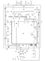
- the sole FIGURE shows a drive device 10 according to the invention for an agricultural utility vehicle, namely a tractor (not shown).
- the drive device 10 comprises an internal combustion engine 12, a radiator 14 of a cooling circuit 16, a generator 18 and a fan 20.
- the internal combustion engine 12, the radiator 14 and the generator 18 are arranged in a dashed line indicated engine compartment 15 of the tractor.
- the cooling circuit 16 conveys coolant of the cooling circuit of the internal combustion engine 12 through the radiator 14. Accordingly, in the schematic illustration with the cooling circuit 16, only the connecting lines are marked.
- the fan 20 air is moved through the radiator 14, which is indicated by the arrows 22. Since the fan 20 is arranged between the radiator 14 and the internal combustion engine 12, the fan 20 sucks in air from the side of the internal combustion engine 12 facing away from the radiator 14.
- the generator 18 is mechanically driven by the crankshaft 24 of the internal combustion engine 12.
- the generator 18 is arranged on the side facing away from the radiator 14 of the internal combustion engine 12.
- the generator 18 is in the form of a crankshaft generator. With the generator 18 electrical energy is generated.
- an electric machine 26 is provided, which can be driven by the electrical energy generated by the generator 18.
- the electric machine 26 in turn drives the fan 20 mechanically.
- the electric machine 26 has an output shaft 28, via which the fan 20 is mechanically drivable.
- the electric machine 26 is arranged in the engine compartment 15 such that the output shaft 28 of the electric machine 26 is arranged in a region of the engine compartment 15 which has a mechanical output 30 of the internal combustion engine 12.
- the mechanical output 30 is a free crankshaft end of the internal combustion engine 12, which has a pulley 32.
- the electric machine 26 is disposed at a location on the engine 12, where usually a conventional alternator is provided.
- a power electronics unit 36 is provided.
- the power electronics unit 36 is supplied to the electric power generated by the generator 18 via the power line 40.
- the power electronics unit 36 is driven by a control device 38.
- the control device 38 in turn controls the power electronics unit 36 in such a way that the direction of rotation and / or the rotational speed and / or the torque of the electric machine 26 can be controlled.
- the electrical current required to operate the electrical machine 26 is conducted via the power line 42.
- a temperature sensor 44 is provided with which the temperature of the coolant of the cooling circuit 16 can be detected.
- the temperature sensor generates electrical signals which are dependent on the detected temperature and which are supplied to the control device 38 via the line 46. It is a driving strategy provided such that the rotational speed of the electric machine 26 in dependence on the coolant temperature of the cooling circuit 16 is controllable.
- the oil cooler 48 is located, through which on the one hand engine oil of the engine 12 is passed.
- coolant in this case, a water-glycerin mixture
- a charge air cooler 50 of the internal combustion engine 12 is provided.
- Both the oil cooler 48 and the intercooler 50 are cooled with coolant of the further cooling circuit 52.
- the further or secondary cooling circuit 52 here only the connecting lines are designated by the reference numeral 52, has an air-coolant heat exchanger 54, which is arranged on the fan 20 remote from the side of the radiator 14.
- the rotational speed of the electric machine is controlled as a function of the oil temperature of the internal combustion engine 12.
- the Oil temperature is detectable with a temperature sensor 56, which also generates an electrical signal that is dependent on the detected temperature and what is supplied via the line 58 of the controller 38.
- the control strategy of the control device 38 also takes into account the instantaneous power requirement of the compressed air compressor 34 when controlling the rotational speed of the electric machine.
- the power electronics unit 36 has a temperature sensor 62 which also generates an electrical signal which is dependent on the detected temperature and transmitted to the control device 38.
- the speed or the torque of the electric machine is also controlled as a function of the temperature of the power electronics 36, in such a way that overheating of the power electronics 36 is excluded.
- the fan 20 and the compressed air compressor 34 are driven by the electric machine 26 via a flexible means 64.
- the flexible means 64 is in the form of a V-belt.
- the fan 20 has a pulley 66.
- the pulley 32 of the mechanical output 30 of the internal combustion engine 12 drives the oil pump 70 via a belt 68.
- the pulley 66 and thus the fan 20 is arranged such that it could also be driven via the pulley 68 of the internal combustion engine 12 by means of a belt, not shown in the figure.
- the generator 18 is in the form of a Welchselstromgenerators.
- the power electronics unit 36 has a DC-DC converter (not shown separately), with which the AC voltage generated by the generator 18 is convertible into DC voltage.
- One of the power electronics unit 36 associated converter (not shown separately) is provided, with which the DC voltage in AC voltage is so convertible that the electric machine 26 is operable at a variable predetermined speed.
- the reference numeral 60 schematically indicates the transmission 12 driven by the internal combustion engine or the traction drive of the commercial vehicle.
- a part of these components, in particular the transmission oil of the transmission 60, could also be connected to a cooling circuit, for example to the further cooling circuit 52, and cooled by these (not shown in the figure).
- Shown only schematically and with the reference numeral 72 is an electrical load of an implement that can be adapted to the tractor.
- This electrical load 72 is also supplied by the power electronics unit 36 via line 74 with electrical power, if the appropriate implement is adapted to the tractor.
- a connector 76 between the vehicle and implement is provided.
Landscapes
- Engineering & Computer Science (AREA)
- Chemical & Material Sciences (AREA)
- Combustion & Propulsion (AREA)
- Mechanical Engineering (AREA)
- General Engineering & Computer Science (AREA)
- Auxiliary Drives, Propulsion Controls, And Safety Devices (AREA)
- Cooling, Air Intake And Gas Exhaust, And Fuel Tank Arrangements In Propulsion Units (AREA)
Applications Claiming Priority (1)
| Application Number | Priority Date | Filing Date | Title |
|---|---|---|---|
| DE102006036589A DE102006036589A1 (de) | 2006-08-04 | 2006-08-04 | Antriebsvorrichtung für ein landwirtschaftliches oder industrielles Nutzfahrzeug und Verfahren zum Betreiben einer Antriebsvorrichtung |
Publications (3)
| Publication Number | Publication Date |
|---|---|
| EP1884635A2 true EP1884635A2 (fr) | 2008-02-06 |
| EP1884635A3 EP1884635A3 (fr) | 2011-08-03 |
| EP1884635B1 EP1884635B1 (fr) | 2018-09-05 |
Family
ID=38662955
Family Applications (1)
| Application Number | Title | Priority Date | Filing Date |
|---|---|---|---|
| EP07113712.9A Active EP1884635B1 (fr) | 2006-08-04 | 2007-08-02 | Dispositif d'entraînement pour un véhicule utilitaire industriel ou agricole et procédé de fonctionnement d'un dispositif d'entraînement |
Country Status (3)
| Country | Link |
|---|---|
| US (1) | US7584722B2 (fr) |
| EP (1) | EP1884635B1 (fr) |
| DE (1) | DE102006036589A1 (fr) |
Families Citing this family (10)
| Publication number | Priority date | Publication date | Assignee | Title |
|---|---|---|---|---|
| JP4702092B2 (ja) * | 2006-02-22 | 2011-06-15 | トヨタ自動車株式会社 | 車両の制御装置および冷却ファンの消費動力推定方法 |
| ITTO20080788A1 (it) | 2008-10-24 | 2010-04-25 | Cnh Italia Spa | Sistema motore |
| US8347994B2 (en) * | 2011-04-13 | 2013-01-08 | Deere & Company | Tractor hood airflow system |
| US10358040B1 (en) * | 2015-06-01 | 2019-07-23 | Hydro-Gear Limited Partnership | Drive assembly and system for utility vehicle |
| US10391854B1 (en) * | 2015-06-15 | 2019-08-27 | Hydro-Gear Limited Partnership | Drive and cooling system for utility vehicle |
| DE102015016725A1 (de) * | 2015-12-22 | 2017-06-22 | Man Diesel & Turbo Se | Steuerungssystem und Verfahren zum Kühlen einer Kraftwerksanlage |
| US10578004B2 (en) * | 2016-08-24 | 2020-03-03 | Denso International America, Inc. | Power booster for engine fans |
| EP4051841A4 (fr) * | 2019-10-31 | 2024-02-21 | Lovis, LLC | Système de pompe motorisée entraînée par prise de force commandée par ordinateur |
| US11685225B2 (en) * | 2019-12-20 | 2023-06-27 | Lovis, Llc | Power takeoff-driven refrigeration |
| US12431764B2 (en) * | 2019-12-20 | 2025-09-30 | Lovis, Llc | Power takeoff-driven refrigeration |
Citations (5)
| Publication number | Priority date | Publication date | Assignee | Title |
|---|---|---|---|---|
| JPS63186910A (ja) | 1987-01-29 | 1988-08-02 | Kubota Ltd | エンジン発電機の冷却装置 |
| US5415134A (en) | 1993-10-29 | 1995-05-16 | Stewart Components | Engine cooling system for cooling a vehicle engine |
| JPH11241368A (ja) | 1998-02-25 | 1999-09-07 | Shin Caterpillar Mitsubishi Ltd | 建設機械の冷却装置 |
| JP2000203274A (ja) | 1999-01-12 | 2000-07-25 | Shin Caterpillar Mitsubishi Ltd | 建設機械の冷却装置 |
| DE102004052023A1 (de) | 2004-10-26 | 2006-04-27 | Deere & Company, Moline | Vorrichtung zum Erzeugen elektrischer Energie für ein landwirtschaftliches oder industrielles Nutzfahrzeug |
Family Cites Families (13)
| Publication number | Priority date | Publication date | Assignee | Title |
|---|---|---|---|---|
| US3853098A (en) * | 1972-10-05 | 1974-12-10 | Nippon Denso Co | Driving system for automobile engine cooling fan |
| JPS6114582Y2 (fr) * | 1979-11-19 | 1986-05-07 | ||
| US6066935A (en) * | 1991-06-03 | 2000-05-23 | Siemens Aktiengesellschaft | Pole-changing asynchronous fan motor with continuously adjustable speed |
| DE19854544B4 (de) * | 1998-11-26 | 2004-06-17 | Mtu Friedrichshafen Gmbh | Kühlsystem für eine aufgeladene Brennkraftmaschine |
| JP3728144B2 (ja) * | 1999-07-01 | 2005-12-21 | デンヨー株式会社 | 防音型エンジン駆動作業機 |
| WO2001084063A2 (fr) * | 2000-05-03 | 2001-11-08 | Horton, Inc. | Systeme de refroidissement pour moteur annulaire a courant continu sans balais |
| DE10041915B4 (de) * | 2000-08-25 | 2016-10-20 | Man Truck & Bus Ag | Kühlsystem für ein Nutzfahrzeug |
| DE10043579B4 (de) * | 2000-09-05 | 2006-04-06 | Mtu Friedrichshafen Gmbh | Brennkraftmaschine mit einer Kühler und Kühlerlüfter enthaltenden Kühlanlage für ein Fahrzeug, insbesondere im Eisenbahnverkehr |
| FR2821895B1 (fr) * | 2001-03-12 | 2003-06-20 | Faurecia Ind | Ensemble de ventilation pour vehicule automobile a variation de puissance continue |
| DE10117245A1 (de) * | 2001-04-06 | 2002-10-17 | Audi Ag | Kühlerlüfter, Kühlsystem und Verfahren zur Steuerung eines Kühlerlüfters |
| DE10320746A1 (de) * | 2003-05-09 | 2004-12-02 | Daimlerchrysler Ag | Erweiterter Lüfternachlauf |
| US7051786B2 (en) | 2003-07-11 | 2006-05-30 | Deere & Company | Vertical airflow engine cooling system |
| JP2006009762A (ja) * | 2004-06-29 | 2006-01-12 | Denyo Co Ltd | エンジン冷却装置 |
-
2006
- 2006-08-04 DE DE102006036589A patent/DE102006036589A1/de not_active Withdrawn
-
2007
- 2007-08-02 EP EP07113712.9A patent/EP1884635B1/fr active Active
- 2007-08-03 US US11/833,467 patent/US7584722B2/en active Active
Patent Citations (5)
| Publication number | Priority date | Publication date | Assignee | Title |
|---|---|---|---|---|
| JPS63186910A (ja) | 1987-01-29 | 1988-08-02 | Kubota Ltd | エンジン発電機の冷却装置 |
| US5415134A (en) | 1993-10-29 | 1995-05-16 | Stewart Components | Engine cooling system for cooling a vehicle engine |
| JPH11241368A (ja) | 1998-02-25 | 1999-09-07 | Shin Caterpillar Mitsubishi Ltd | 建設機械の冷却装置 |
| JP2000203274A (ja) | 1999-01-12 | 2000-07-25 | Shin Caterpillar Mitsubishi Ltd | 建設機械の冷却装置 |
| DE102004052023A1 (de) | 2004-10-26 | 2006-04-27 | Deere & Company, Moline | Vorrichtung zum Erzeugen elektrischer Energie für ein landwirtschaftliches oder industrielles Nutzfahrzeug |
Also Published As
| Publication number | Publication date |
|---|---|
| US20080121195A1 (en) | 2008-05-29 |
| EP1884635B1 (fr) | 2018-09-05 |
| US7584722B2 (en) | 2009-09-08 |
| EP1884635A3 (fr) | 2011-08-03 |
| DE102006036589A1 (de) | 2008-02-07 |
Similar Documents
| Publication | Publication Date | Title |
|---|---|---|
| EP1884635B1 (fr) | Dispositif d'entraînement pour un véhicule utilitaire industriel ou agricole et procédé de fonctionnement d'un dispositif d'entraînement | |
| EP3006245B1 (fr) | Procede de commande de transmission | |
| DE69702806T2 (de) | Hybridantrieb mit Zusatzantrieben | |
| EP3192167B1 (fr) | Procédé et disposition de climatisation de l'intérieur d'un véhicule à entraînement électrique | |
| EP1769144B1 (fr) | Systeme de refroidissement pour un vehicule | |
| DE10153586A1 (de) | System und Verfahren zur Steuerung des Kühlmittelflusses für Fahrzeuge | |
| EP2990610B1 (fr) | Moteur d'avion et procede de fonctionnement d'un moteur d'avion | |
| DE102008006578A1 (de) | Fahrzeugantriebssystem, Leistungssteuerungsvorrichtung und Verfahren zum Steuern von Leistung | |
| EP3390127A1 (fr) | Chaîne cinématique pour un véhicule | |
| DE102019203730A1 (de) | Verfahren zum Betreiben eines Antriebsstrangs für eine Arbeitsmaschine, Antriebsstrang für eine Arbeitsmaschine und Arbeitsmaschine | |
| DE10334501A1 (de) | Fahrzeugverbrennungsmotorkühlsystem mit Wasserpumpe mit variabler Drehzahl | |
| DE10334024A1 (de) | Verbrennungsmotorkühlsystem mit Ventilator mit variabler Drehzahl | |
| DE10016435B4 (de) | Lüftungseinrichtung für ein landwirtschaftliches Fahrzeug | |
| DE102011006350A1 (de) | Lüftungsvorrichtung für ein Kühlmodul insbesondere in einem Fahrzeug, Verfahren zum Betreiben einer Lüftungsvorrichtung und Kühlsystem insbesondere für ein Fahrzeug | |
| DE102004002761A1 (de) | Verfahren zum Betrieb eines Antriebsstrangs eines Kraftfahrzeugs | |
| DE4425387C1 (de) | Landwirtschaftlicher Traktor mit elektromechanischem Getriebe | |
| EP1451457B1 (fr) | Mecanisme d'entrainement pour unites auxiliaires | |
| DE102004052023A1 (de) | Vorrichtung zum Erzeugen elektrischer Energie für ein landwirtschaftliches oder industrielles Nutzfahrzeug | |
| DE102018128650B4 (de) | Hybrid-Antriebssystem für ein elektrisch zumindest teilweise antreibbares Kraftfahrzeug | |
| DE10023508B4 (de) | Kühlanlage eines flüssigkeitsgekühlten Verbrennungsmotors | |
| EP0556477B1 (fr) | Entraînement hydrostatique-mécanique des accessoires d'un véhicule automobile, notamment ventilateur, générateur, pompe à eau | |
| DE102016220847B4 (de) | Verfahren zum Betreiben einer Antriebseinrichtung für ein Kraftfahrzeug mit Nutzung der bei einem Laden eines Energiespeichers anfallenden Wärme zum Aufheizen eines Antriebsaggregats und/oder eines Getriebes sowie entsprechende Antriebseinrichtung | |
| DE102014106253A1 (de) | Wärmetauscheranordnung für eine Antriebseinheit einer landwirschaftlichen Arbeitsmaschine | |
| CH706518A1 (de) | Steuerung für das Antriebssystem einer Arbeitsmaschine. | |
| DE10127893A1 (de) | Modulare Vorrichtung zur Energieerzeugung |
Legal Events
| Date | Code | Title | Description |
|---|---|---|---|
| PUAI | Public reference made under article 153(3) epc to a published international application that has entered the european phase |
Free format text: ORIGINAL CODE: 0009012 |
|
| AK | Designated contracting states |
Kind code of ref document: A2 Designated state(s): AT BE BG CH CY CZ DE DK EE ES FI FR GB GR HU IE IS IT LI LT LU LV MC MT NL PL PT RO SE SI SK TR |
|
| AX | Request for extension of the european patent |
Extension state: AL BA HR MK YU |
|
| PUAL | Search report despatched |
Free format text: ORIGINAL CODE: 0009013 |
|
| RIC1 | Information provided on ipc code assigned before grant |
Ipc: F01P 11/10 20060101ALN20071115BHEP Ipc: F02B 67/08 20060101ALI20110622BHEP Ipc: F01P 7/04 20060101AFI20071115BHEP |
|
| AK | Designated contracting states |
Kind code of ref document: A3 Designated state(s): AT BE BG CH CY CZ DE DK EE ES FI FR GB GR HU IE IS IT LI LT LU LV MC MT NL PL PT RO SE SI SK TR |
|
| AX | Request for extension of the european patent |
Extension state: AL BA HR MK RS |
|
| 17P | Request for examination filed |
Effective date: 20120203 |
|
| AKX | Designation fees paid |
Designated state(s): AT BE BG CH CY CZ DE DK EE ES FI FR GB GR HU IE IS IT LI LT LU LV MC MT NL PL PT RO SE SI SK TR |
|
| STAA | Information on the status of an ep patent application or granted ep patent |
Free format text: STATUS: EXAMINATION IS IN PROGRESS |
|
| 17Q | First examination report despatched |
Effective date: 20161213 |
|
| RIC1 | Information provided on ipc code assigned before grant |
Ipc: F01P 11/10 20060101ALN20180125BHEP Ipc: F01P 7/04 20060101AFI20180125BHEP Ipc: F02B 67/08 20060101ALI20180125BHEP |
|
| GRAP | Despatch of communication of intention to grant a patent |
Free format text: ORIGINAL CODE: EPIDOSNIGR1 |
|
| STAA | Information on the status of an ep patent application or granted ep patent |
Free format text: STATUS: GRANT OF PATENT IS INTENDED |
|
| INTG | Intention to grant announced |
Effective date: 20180320 |
|
| GRAS | Grant fee paid |
Free format text: ORIGINAL CODE: EPIDOSNIGR3 |
|
| GRAA | (expected) grant |
Free format text: ORIGINAL CODE: 0009210 |
|
| STAA | Information on the status of an ep patent application or granted ep patent |
Free format text: STATUS: THE PATENT HAS BEEN GRANTED |
|
| AK | Designated contracting states |
Kind code of ref document: B1 Designated state(s): AT BE BG CH CY CZ DE DK EE ES FI FR GB GR HU IE IS IT LI LT LU LV MC MT NL PL PT RO SE SI SK TR |
|
| REG | Reference to a national code |
Ref country code: GB Ref legal event code: FG4D Free format text: NOT ENGLISH |
|
| REG | Reference to a national code |
Ref country code: CH Ref legal event code: EP |
|
| REG | Reference to a national code |
Ref country code: AT Ref legal event code: REF Ref document number: 1038065 Country of ref document: AT Kind code of ref document: T Effective date: 20180915 |
|
| REG | Reference to a national code |
Ref country code: IE Ref legal event code: FG4D Free format text: LANGUAGE OF EP DOCUMENT: GERMAN |
|
| REG | Reference to a national code |
Ref country code: DE Ref legal event code: R096 Ref document number: 502007016370 Country of ref document: DE |
|
| REG | Reference to a national code |
Ref country code: SE Ref legal event code: TRGR |
|
| REG | Reference to a national code |
Ref country code: NL Ref legal event code: MP Effective date: 20180905 |
|
| REG | Reference to a national code |
Ref country code: LT Ref legal event code: MG4D |
|
| PG25 | Lapsed in a contracting state [announced via postgrant information from national office to epo] |
Ref country code: BG Free format text: LAPSE BECAUSE OF FAILURE TO SUBMIT A TRANSLATION OF THE DESCRIPTION OR TO PAY THE FEE WITHIN THE PRESCRIBED TIME-LIMIT Effective date: 20181205 Ref country code: LT Free format text: LAPSE BECAUSE OF FAILURE TO SUBMIT A TRANSLATION OF THE DESCRIPTION OR TO PAY THE FEE WITHIN THE PRESCRIBED TIME-LIMIT Effective date: 20180905 Ref country code: GR Free format text: LAPSE BECAUSE OF FAILURE TO SUBMIT A TRANSLATION OF THE DESCRIPTION OR TO PAY THE FEE WITHIN THE PRESCRIBED TIME-LIMIT Effective date: 20181206 |
|
| PG25 | Lapsed in a contracting state [announced via postgrant information from national office to epo] |
Ref country code: ES Free format text: LAPSE BECAUSE OF FAILURE TO SUBMIT A TRANSLATION OF THE DESCRIPTION OR TO PAY THE FEE WITHIN THE PRESCRIBED TIME-LIMIT Effective date: 20180905 Ref country code: LV Free format text: LAPSE BECAUSE OF FAILURE TO SUBMIT A TRANSLATION OF THE DESCRIPTION OR TO PAY THE FEE WITHIN THE PRESCRIBED TIME-LIMIT Effective date: 20180905 |
|
| PG25 | Lapsed in a contracting state [announced via postgrant information from national office to epo] |
Ref country code: EE Free format text: LAPSE BECAUSE OF FAILURE TO SUBMIT A TRANSLATION OF THE DESCRIPTION OR TO PAY THE FEE WITHIN THE PRESCRIBED TIME-LIMIT Effective date: 20180905 Ref country code: NL Free format text: LAPSE BECAUSE OF FAILURE TO SUBMIT A TRANSLATION OF THE DESCRIPTION OR TO PAY THE FEE WITHIN THE PRESCRIBED TIME-LIMIT Effective date: 20180905 Ref country code: PL Free format text: LAPSE BECAUSE OF FAILURE TO SUBMIT A TRANSLATION OF THE DESCRIPTION OR TO PAY THE FEE WITHIN THE PRESCRIBED TIME-LIMIT Effective date: 20180905 Ref country code: CZ Free format text: LAPSE BECAUSE OF FAILURE TO SUBMIT A TRANSLATION OF THE DESCRIPTION OR TO PAY THE FEE WITHIN THE PRESCRIBED TIME-LIMIT Effective date: 20180905 Ref country code: IS Free format text: LAPSE BECAUSE OF FAILURE TO SUBMIT A TRANSLATION OF THE DESCRIPTION OR TO PAY THE FEE WITHIN THE PRESCRIBED TIME-LIMIT Effective date: 20190105 Ref country code: RO Free format text: LAPSE BECAUSE OF FAILURE TO SUBMIT A TRANSLATION OF THE DESCRIPTION OR TO PAY THE FEE WITHIN THE PRESCRIBED TIME-LIMIT Effective date: 20180905 |
|
| PG25 | Lapsed in a contracting state [announced via postgrant information from national office to epo] |
Ref country code: SK Free format text: LAPSE BECAUSE OF FAILURE TO SUBMIT A TRANSLATION OF THE DESCRIPTION OR TO PAY THE FEE WITHIN THE PRESCRIBED TIME-LIMIT Effective date: 20180905 Ref country code: PT Free format text: LAPSE BECAUSE OF FAILURE TO SUBMIT A TRANSLATION OF THE DESCRIPTION OR TO PAY THE FEE WITHIN THE PRESCRIBED TIME-LIMIT Effective date: 20190105 |
|
| REG | Reference to a national code |
Ref country code: DE Ref legal event code: R097 Ref document number: 502007016370 Country of ref document: DE |
|
| PLBE | No opposition filed within time limit |
Free format text: ORIGINAL CODE: 0009261 |
|
| STAA | Information on the status of an ep patent application or granted ep patent |
Free format text: STATUS: NO OPPOSITION FILED WITHIN TIME LIMIT |
|
| PG25 | Lapsed in a contracting state [announced via postgrant information from national office to epo] |
Ref country code: DK Free format text: LAPSE BECAUSE OF FAILURE TO SUBMIT A TRANSLATION OF THE DESCRIPTION OR TO PAY THE FEE WITHIN THE PRESCRIBED TIME-LIMIT Effective date: 20180905 |
|
| 26N | No opposition filed |
Effective date: 20190606 |
|
| PG25 | Lapsed in a contracting state [announced via postgrant information from national office to epo] |
Ref country code: SI Free format text: LAPSE BECAUSE OF FAILURE TO SUBMIT A TRANSLATION OF THE DESCRIPTION OR TO PAY THE FEE WITHIN THE PRESCRIBED TIME-LIMIT Effective date: 20180905 |
|
| PG25 | Lapsed in a contracting state [announced via postgrant information from national office to epo] |
Ref country code: TR Free format text: LAPSE BECAUSE OF FAILURE TO SUBMIT A TRANSLATION OF THE DESCRIPTION OR TO PAY THE FEE WITHIN THE PRESCRIBED TIME-LIMIT Effective date: 20180905 |
|
| GBPC | Gb: european patent ceased through non-payment of renewal fee |
Effective date: 20190802 |
|
| PG25 | Lapsed in a contracting state [announced via postgrant information from national office to epo] |
Ref country code: LI Free format text: LAPSE BECAUSE OF NON-PAYMENT OF DUE FEES Effective date: 20190831 Ref country code: CH Free format text: LAPSE BECAUSE OF NON-PAYMENT OF DUE FEES Effective date: 20190831 Ref country code: LU Free format text: LAPSE BECAUSE OF NON-PAYMENT OF DUE FEES Effective date: 20190802 Ref country code: MC Free format text: LAPSE BECAUSE OF FAILURE TO SUBMIT A TRANSLATION OF THE DESCRIPTION OR TO PAY THE FEE WITHIN THE PRESCRIBED TIME-LIMIT Effective date: 20180905 |
|
| REG | Reference to a national code |
Ref country code: BE Ref legal event code: MM Effective date: 20190831 |
|
| PG25 | Lapsed in a contracting state [announced via postgrant information from national office to epo] |
Ref country code: IE Free format text: LAPSE BECAUSE OF NON-PAYMENT OF DUE FEES Effective date: 20190802 |
|
| PG25 | Lapsed in a contracting state [announced via postgrant information from national office to epo] |
Ref country code: BE Free format text: LAPSE BECAUSE OF NON-PAYMENT OF DUE FEES Effective date: 20190831 Ref country code: GB Free format text: LAPSE BECAUSE OF NON-PAYMENT OF DUE FEES Effective date: 20190802 |
|
| PG25 | Lapsed in a contracting state [announced via postgrant information from national office to epo] |
Ref country code: CY Free format text: LAPSE BECAUSE OF FAILURE TO SUBMIT A TRANSLATION OF THE DESCRIPTION OR TO PAY THE FEE WITHIN THE PRESCRIBED TIME-LIMIT Effective date: 20180905 |
|
| PG25 | Lapsed in a contracting state [announced via postgrant information from national office to epo] |
Ref country code: MT Free format text: LAPSE BECAUSE OF FAILURE TO SUBMIT A TRANSLATION OF THE DESCRIPTION OR TO PAY THE FEE WITHIN THE PRESCRIBED TIME-LIMIT Effective date: 20180905 Ref country code: HU Free format text: LAPSE BECAUSE OF FAILURE TO SUBMIT A TRANSLATION OF THE DESCRIPTION OR TO PAY THE FEE WITHIN THE PRESCRIBED TIME-LIMIT; INVALID AB INITIO Effective date: 20070802 |
|
| PGFP | Annual fee paid to national office [announced via postgrant information from national office to epo] |
Ref country code: FI Payment date: 20250825 Year of fee payment: 19 |
|
| PGFP | Annual fee paid to national office [announced via postgrant information from national office to epo] |
Ref country code: DE Payment date: 20250721 Year of fee payment: 19 |
|
| PGFP | Annual fee paid to national office [announced via postgrant information from national office to epo] |
Ref country code: IT Payment date: 20250820 Year of fee payment: 19 |
|
| PGFP | Annual fee paid to national office [announced via postgrant information from national office to epo] |
Ref country code: FR Payment date: 20250825 Year of fee payment: 19 Ref country code: AT Payment date: 20250827 Year of fee payment: 19 |
|
| PGFP | Annual fee paid to national office [announced via postgrant information from national office to epo] |
Ref country code: SE Payment date: 20250827 Year of fee payment: 19 |