EP1884635A2 - Power transmission device for agricultural or industrial vehicles and method for operating such a power transmission device - Google Patents
Power transmission device for agricultural or industrial vehicles and method for operating such a power transmission device Download PDFInfo
- Publication number
- EP1884635A2 EP1884635A2 EP07113712A EP07113712A EP1884635A2 EP 1884635 A2 EP1884635 A2 EP 1884635A2 EP 07113712 A EP07113712 A EP 07113712A EP 07113712 A EP07113712 A EP 07113712A EP 1884635 A2 EP1884635 A2 EP 1884635A2
- Authority
- EP
- European Patent Office
- Prior art keywords
- electric machine
- fan
- drive device
- generator
- internal combustion
- Prior art date
- Legal status (The legal status is an assumption and is not a legal conclusion. Google has not performed a legal analysis and makes no representation as to the accuracy of the status listed.)
- Granted
Links
Images
Classifications
-
- F—MECHANICAL ENGINEERING; LIGHTING; HEATING; WEAPONS; BLASTING
- F01—MACHINES OR ENGINES IN GENERAL; ENGINE PLANTS IN GENERAL; STEAM ENGINES
- F01P—COOLING OF MACHINES OR ENGINES IN GENERAL; COOLING OF INTERNAL-COMBUSTION ENGINES
- F01P7/00—Controlling of coolant flow
- F01P7/02—Controlling of coolant flow the coolant being cooling-air
- F01P7/04—Controlling of coolant flow the coolant being cooling-air by varying pump speed, e.g. by changing pump-drive gear ratio
- F01P7/048—Controlling of coolant flow the coolant being cooling-air by varying pump speed, e.g. by changing pump-drive gear ratio using electrical drives
-
- F—MECHANICAL ENGINEERING; LIGHTING; HEATING; WEAPONS; BLASTING
- F02—COMBUSTION ENGINES; HOT-GAS OR COMBUSTION-PRODUCT ENGINE PLANTS
- F02B—INTERNAL-COMBUSTION PISTON ENGINES; COMBUSTION ENGINES IN GENERAL
- F02B67/00—Engines characterised by the arrangement of auxiliary apparatus not being otherwise provided for, e.g. the apparatus having different functions; Driving auxiliary apparatus from engines, not otherwise provided for
- F02B67/08—Engines characterised by the arrangement of auxiliary apparatus not being otherwise provided for, e.g. the apparatus having different functions; Driving auxiliary apparatus from engines, not otherwise provided for of non-mechanically driven auxiliary apparatus
-
- F—MECHANICAL ENGINEERING; LIGHTING; HEATING; WEAPONS; BLASTING
- F01—MACHINES OR ENGINES IN GENERAL; ENGINE PLANTS IN GENERAL; STEAM ENGINES
- F01P—COOLING OF MACHINES OR ENGINES IN GENERAL; COOLING OF INTERNAL-COMBUSTION ENGINES
- F01P11/00—Component parts, details, or accessories not provided for in, or of interest apart from, groups F01P1/00 - F01P9/00
- F01P11/10—Guiding or ducting cooling-air, to, or from, liquid-to-air heat exchangers
Definitions
- the invention relates to a drive device for an agricultural or industrial utility vehicle.
- the drive device comprises an internal combustion engine, a radiator of a cooling circuit, a generator and a fan. Air can be moved through the radiator with the fan.
- the fan is located adjacent to the radiator.
- the fan, the internal combustion engine and the radiator are arranged in an engine compartment. Accordingly, the fan could be arranged between the radiator and the internal combustion engine or on the side facing away from the engine of the radiator. In the latter case, the fan could be driven by a shaft passing through the radiator at one location.
- the generator is mechanically drivable by the internal combustion engine.
- the generator is mechanically drivable by a side of the internal combustion engine facing the radiator. With the generator electrical energy or electrical power can be generated.
- the present invention relates to a method for operating a drive device.
- Drive devices of the type mentioned are known from the prior art, in particular from the field of passenger vehicles. Furthermore, these drive devices are common in agricultural or industrial commercial vehicles, where, however, high mechanical performance must be applied at low speeds, for example in field work with a tractor or earthworks with construction equipment. Accordingly, it is necessary that with the help of the fan always a sufficient amount of air is moved through the radiator. Therefore, the performance of the fan drive is too high dimensioned so that even at low speeds, the engine is sufficiently cooled.
- radiator fans that is fans for radiators or for air-coolant heat exchangers
- an internal combustion engine usually has a belt drive on a side facing the radiator.
- the drive of the fan via a belt or similar means purely mechanical, the cooler always has a speed due to the direct belt coupling, which is dependent on the speed of the engine.
- An adaptation of the fan speed such that the fan is operable at a speed which is adapted to the current requirements for the cooling capacity of the radiator is not readily possible in this case.
- the present invention is therefore an object of the invention to provide a drive device and a method for operating a drive device of the type mentioned and further, by which the aforementioned problems are overcome.
- the fan should be operable at a speed which is adapted to the current requirements for the cooling capacity of the radiator or the cooling system of the internal combustion engine and thus is independent of the speed of the internal combustion engine adjustable.
- a drive device of the type mentioned above is characterized in that an electric machine is provided, which is drivable with the electrical energy generated by the generator and with which the fan is mechanically driven.
- cooling fans in vehicles serve to generate the air mass flow necessary for heat removal from the radiator or cooler package.
- the design of the systems is based on the so-called worst case, ie the operation of the vehicle under high load at low speeds and ambient temperatures.
- the radiator fans are mechanically driven by a belt drive from the crankshaft of the vehicle.
- viscous coupling that is used an element for temperature-dependent speed position.
- the speed setting can only take place in the direction of "reduction”, i. the speed of the fan is directly dependent on the speed of the internal combustion engine or lower or zero, if the viscous coupling is disengaged. This is based on the functional principle of producing viscous slip.
- Another possibility is the use of electromagnetically actuated clutches.
- Electric fan drives are used in the automotive sector. These are available both in two-point controller version (on / off) and as speed-controlled drives in vehicles with high cooling capacity requirements. Electric fan drives are therefore also an interesting alternative for commercial vehicles.
- the fan drive power required for these vehicles is approx. 5-10% of the nominal rated engine output and has considerable requirements for installation space and costs.
- the direct drive design i.e., the fan motor drives the fan without the intermediate gearbox
- the conventional alternator ie, the conventional electric generator
- the conventional alternator is also driven via a belt drive from the engine output driven pulley, and thus is disposed in a region in the engine compartment which is adjacent to or adjacent to the radiator facing side of the engine is provided.
- the generator for generating the electric current is therefore mechanically driven by a side of the internal combustion engine that faces the radiator. This could for example be in the form of a crankshaft generator, as in the DE 10 2004 052 023 is described. There, the generator is arranged on the side facing the internal combustion engine transmission facing side of the engine.
- the rotor of the generator is driven by the crankshaft of the internal combustion engine, with which also the transmission and the traction drive is driven.
- the crankshaft generator described therein comprises an asynchronous machine which generates three-phase current of a frequency that is dependent on the currently present rotational speed of the internal combustion engine. This three-phase current is converted into direct current by means of an AC / DC converter and fed to a DC intermediate circuit. If an electric machine is to be operated with alternating or three-phase current, a DC / AC converter should be provided between the DC intermediate circuit and the electrical machine with which the direct current can be converted into alternating or three-phase current of predefinable frequency.
- the electric machine With at least a portion of the current generated by the generator then the electric machine can be driven, which in turn mechanically drives the fan.
- the electric machine is arranged at an area in the engine compartment, which is provided on or spatially adjacent to the cooler side facing the engine. Specifically, this could be where the conventional alternator of the vehicle is usually mounted. Further details follow below.
- the electric machine could have an output shaft, via which the fan is mechanically drivable.
- the rotor of the electric machine is rigidly connected to the output shaft.
- the electric machine is arranged in the engine compartment such that the output shaft of the electric machine is arranged in a region of the engine compartment which has a mechanical output of the internal combustion engine.
- a mechanical drive could for example be a free crankshaft end of the internal combustion engine, which could have a pulley.
- the pulley usually drives the radiator fan, a coolant pump, an engine or transmission oil pump, an alternator for generating electrical energy and / or a compressed air compressor.
- the mechanical drive shaft of the fan is arranged in a region of the pulley of the internal combustion engine, but the fan is not driven by the belt directly from the internal combustion engine, the electric machine and its output shaft is expediently also arranged in this region, so that the fan mechanically from the electric machine can be driven.
- the concept according to the invention can be realized while maintaining the usual and proven configuration in the engine compartment. Accordingly, it is not necessary to change the internal combustion engine in terms of additional or modified mechanical output.
- the location of the radiator and the fan as well as the other auxiliary units can remain unchanged.
- the electric machine could be located at a building site on the internal combustion engine, where conventionally a conventional alternator is provided. Since the fan can be driven mechanically by the electric machine and thus the generator mechanically driven there usually is not operated as a mechanical consumer, this space which has become free can be used in the case of the drive device mentioned above for the electric machine. This is also advantageous because - as already mentioned - the basic arrangement of the other components in the engine compartment does not need to be changed.
- further consumers are mechanically drivable with the electric machine, for example a compressed air compressor.
- the electric machine for example a compressed air compressor.
- consumers come into question, which are likewise to be operated depending on the current or currently available power requirement of the vehicle.
- a power electronics unit controlled by a control device which has power electronics components and with which the direction of rotation, speed and / or or the torque of the electric machine is controllable.
- control strategies are described with which the components of the vehicle and In particular, the fan can be controlled or regulated.
- the rotational speed and / or the torque of the electric machine can be controlled as a function of the coolant temperature of the cooling circuit, optionally of a further cooling circuit. If the coolant temperature is higher, the fan speed will increase accordingly. This makes possible an appropriate control and regulation adapted to the currently existing load state of the cooling system of the vehicle.
- the speed and / or the torque of the electric machine could be controllable in dependence on the oil temperature of the internal combustion engine, the drive train and / or a vehicle hydraulic system. This enables a demand-controlled and / or closed-loop control adapted to the currently existing load state of the internal combustion engine and / or the drive train or the components of the vehicle hydraulic system.
- the rotational speed and / or the torque of the electric machine can be controlled as a function of the power requirement of further electrical consumers of the vehicle, for example an air conditioning system.
- a corresponding control of the generator can be included.
- the electric power supplied to the fan could be reduced if another electrical load is to be supplied and the coolant temperature of the cooling circuit permits this.
- a working device coupled to the tractor or utility vehicle could be operated at least partially electrically.
- the or the electric Consumers of the implement could accordingly also be supplied electrically by the generator of the utility vehicle / tractor.
- the rotational speed and / or the torque of the electric machine can be controlled as a function of the power requirement of an electrical load of an implement which can be coupled to the vehicle.
- An example of such a working implement is a drill or seeder.
- the rotational speed and / or the torque of the electric machine could be controllable in dependence on the demand of a pneumatic compressor.
- a control of the rotational speed and / or the torque of the electric machine as a function of the temperature of the coolant of a secondary cooling circuit is conceivable. This is of particular interest when the fan moves air through a cooler of the secondary cooling circuit.
- the rotational speed and / or the torque of the electric machine could be controllable as a function of the temperature of a charge air cooler and / or the coolant temperature of a cooling circuit with which the charge air cooler can be cooled.
- the operating temperature of the power electronics or the power electronics unit could be taken into account, so that the rotational speed and / or the torque of the electric machine in response to the temperature of the power electronics can be controlled.
- At least one temperature sensor is provided, which is arranged such that the temperature of a component or a coolant or an oil is detectable.
- the temperature sensor generates a signal which can be transmitted to a control device.
- the fan is driven by a flexible means of the electric machine.
- the fan could have a pulley and be arranged or fixed spatially in the engine compartment of the vehicle such that the pulley of the fan is arranged such that it also - for example by means of a belt - via a pulley of the crankshaft of the engine by means of a belt - quasi conventional - would be drivable.
- the fan could be mounted unchanged and on the usually provided conventional cultivation location.
- the fan is not driven by a belt via the pulley of the internal combustion engine, but for example via a belt which is driven by a pulley of the electric machine.
- the belt drive of the internal combustion engine for, for example, the water and / or oil pump is to be modified in such a way that the fan is no longer driven by this belt drive.
- the electric machine can be mounted and it is to provide a belt drive to drive the fan, provided that the generator provided for operating the electric machine is mounted at a different location.
- the flexible means could comprise a belt, a V-belt, V-ribs, a toothed belt or a chain.
- the gear ratio could here - as well as in a pure belt drive of the fan of the electric machine with a predetermined ratio - in similar areas as in the alternator, ie about 1: 3 to 1: 4.
- the resulting relatively high speeds lead advantageously to a compact machine design and corresponding to a direct drive reduced costs for the electric motor. Since the rotational speeds and the size of the rotating parts within the machine are approximately equal to those of an alternator, no disadvantage in terms of the life is expected.
- the generator could have an AC generator, in particular an asynchronous machine.
- a DC-DC converter could be provided, with which the AC voltage generated by the generator can be converted into DC voltage.
- the converted DC voltage could be fed to a DC intermediate circuit.
- the power electronics unit associated - be provided with which the DC voltage (eg the DC intermediate circuit) is converted into AC voltage such that the electric machine is operable with a variable predetermined speed. This speed can then be selected such that the expected, generated by the fan air movement through the cooler provides a predetermined, currently required cooling capacity. Finally, the speed of the electric machine can be commanded according to at least one of the above-mentioned drive strategies.
- the inventive method is used to operate a drive device for an agricultural or industrial utility vehicle.
- the drive device comprises an internal combustion engine, a radiator of a cooling circuit, a generator and a fan.
- the fan moves air through the radiator.
- the fan is located adjacent to the radiator.
- the fan, the internal combustion engine and the radiator are arranged in an engine compartment.
- the generator is mechanically driven by the internal combustion engine.
- the generator is mechanically driven by a side other than the radiator facing side of the engine.
- the generator generates electrical energy.
- an electrical machine is provided, which is driven by the electrical energy generated by the generator and with which the fan is mechanically driven.
- the method for operating a drive device according to one of claims 1 to 21 is provided.
- the method could have the appropriate control or regulating steps, as described with the claims 7 to 15 together with the associated description part.
- the inventive method and / or its preferred embodiments includes method steps for operating the Components of claims 1 to 21, wherein the method steps will be apparent to those skilled in the knowledge of the disclosure of the part of the present application relating to the drive device. Therefore, to avoid repetition, reference is made to the preceding part of the description and to the corresponding claims.
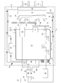
- the sole FIGURE shows a drive device 10 according to the invention for an agricultural utility vehicle, namely a tractor (not shown).
- the drive device 10 comprises an internal combustion engine 12, a radiator 14 of a cooling circuit 16, a generator 18 and a fan 20.
- the internal combustion engine 12, the radiator 14 and the generator 18 are arranged in a dashed line indicated engine compartment 15 of the tractor.
- the cooling circuit 16 conveys coolant of the cooling circuit of the internal combustion engine 12 through the radiator 14. Accordingly, in the schematic illustration with the cooling circuit 16, only the connecting lines are marked.
- the fan 20 air is moved through the radiator 14, which is indicated by the arrows 22. Since the fan 20 is arranged between the radiator 14 and the internal combustion engine 12, the fan 20 sucks in air from the side of the internal combustion engine 12 facing away from the radiator 14.
- the generator 18 is mechanically driven by the crankshaft 24 of the internal combustion engine 12.
- the generator 18 is arranged on the side facing away from the radiator 14 of the internal combustion engine 12.
- the generator 18 is in the form of a crankshaft generator. With the generator 18 electrical energy is generated.
- an electric machine 26 is provided, which can be driven by the electrical energy generated by the generator 18.
- the electric machine 26 in turn drives the fan 20 mechanically.
- the electric machine 26 has an output shaft 28, via which the fan 20 is mechanically drivable.
- the electric machine 26 is arranged in the engine compartment 15 such that the output shaft 28 of the electric machine 26 is arranged in a region of the engine compartment 15 which has a mechanical output 30 of the internal combustion engine 12.
- the mechanical output 30 is a free crankshaft end of the internal combustion engine 12, which has a pulley 32.
- the electric machine 26 is disposed at a location on the engine 12, where usually a conventional alternator is provided.
- a power electronics unit 36 is provided.
- the power electronics unit 36 is supplied to the electric power generated by the generator 18 via the power line 40.
- the power electronics unit 36 is driven by a control device 38.
- the control device 38 in turn controls the power electronics unit 36 in such a way that the direction of rotation and / or the rotational speed and / or the torque of the electric machine 26 can be controlled.
- the electrical current required to operate the electrical machine 26 is conducted via the power line 42.
- a temperature sensor 44 is provided with which the temperature of the coolant of the cooling circuit 16 can be detected.
- the temperature sensor generates electrical signals which are dependent on the detected temperature and which are supplied to the control device 38 via the line 46. It is a driving strategy provided such that the rotational speed of the electric machine 26 in dependence on the coolant temperature of the cooling circuit 16 is controllable.
- the oil cooler 48 is located, through which on the one hand engine oil of the engine 12 is passed.
- coolant in this case, a water-glycerin mixture
- a charge air cooler 50 of the internal combustion engine 12 is provided.
- Both the oil cooler 48 and the intercooler 50 are cooled with coolant of the further cooling circuit 52.
- the further or secondary cooling circuit 52 here only the connecting lines are designated by the reference numeral 52, has an air-coolant heat exchanger 54, which is arranged on the fan 20 remote from the side of the radiator 14.
- the rotational speed of the electric machine is controlled as a function of the oil temperature of the internal combustion engine 12.
- the Oil temperature is detectable with a temperature sensor 56, which also generates an electrical signal that is dependent on the detected temperature and what is supplied via the line 58 of the controller 38.
- the control strategy of the control device 38 also takes into account the instantaneous power requirement of the compressed air compressor 34 when controlling the rotational speed of the electric machine.
- the power electronics unit 36 has a temperature sensor 62 which also generates an electrical signal which is dependent on the detected temperature and transmitted to the control device 38.
- the speed or the torque of the electric machine is also controlled as a function of the temperature of the power electronics 36, in such a way that overheating of the power electronics 36 is excluded.
- the fan 20 and the compressed air compressor 34 are driven by the electric machine 26 via a flexible means 64.
- the flexible means 64 is in the form of a V-belt.
- the fan 20 has a pulley 66.
- the pulley 32 of the mechanical output 30 of the internal combustion engine 12 drives the oil pump 70 via a belt 68.
- the pulley 66 and thus the fan 20 is arranged such that it could also be driven via the pulley 68 of the internal combustion engine 12 by means of a belt, not shown in the figure.
- the generator 18 is in the form of a Welchselstromgenerators.
- the power electronics unit 36 has a DC-DC converter (not shown separately), with which the AC voltage generated by the generator 18 is convertible into DC voltage.
- One of the power electronics unit 36 associated converter (not shown separately) is provided, with which the DC voltage in AC voltage is so convertible that the electric machine 26 is operable at a variable predetermined speed.
- the reference numeral 60 schematically indicates the transmission 12 driven by the internal combustion engine or the traction drive of the commercial vehicle.
- a part of these components, in particular the transmission oil of the transmission 60, could also be connected to a cooling circuit, for example to the further cooling circuit 52, and cooled by these (not shown in the figure).
- Shown only schematically and with the reference numeral 72 is an electrical load of an implement that can be adapted to the tractor.
- This electrical load 72 is also supplied by the power electronics unit 36 via line 74 with electrical power, if the appropriate implement is adapted to the tractor.
- a connector 76 between the vehicle and implement is provided.
Landscapes
- Engineering & Computer Science (AREA)
- Chemical & Material Sciences (AREA)
- Combustion & Propulsion (AREA)
- Mechanical Engineering (AREA)
- General Engineering & Computer Science (AREA)
- Auxiliary Drives, Propulsion Controls, And Safety Devices (AREA)
- Cooling, Air Intake And Gas Exhaust, And Fuel Tank Arrangements In Propulsion Units (AREA)
Abstract
Description
Die Erfindung betrifft eine Antriebsvorrichtung für ein landwirtschaftliches oder industrielles Nutzfahrzeug. Die Antriebsvorrichtung umfasst einen Verbrennungsmotor, einen Kühler eines Kühlkreislaufs, einen Generator und einen Lüfter. Mit dem Lüfter ist Luft durch den Kühler bewegbar. Der Lüfter ist benachbart zum Kühler angeordnet. Der Lüfter, der Verbrennungsmotor und der Kühler sind in einem Motorraum angeordnet. Dementsprechend könnte der Lüfter zwischen dem Kühler und dem Verbrennungsmotor oder auf der dem Verbrennungsmotor abgewandten Seite des Kühlers angeordnet sein. Im letztgenannten Fall könnte der Lüfter über eine Welle angetrieben werden, die an einer Stelle durch den Kühler hindurchgeführt ist. Der Generator ist vom Verbrennungsmotor mechanisch antreibbar. Der Generator ist von einer anderen als der dem Kühler zugewandten Seite des Verbrennungsmotors mechanisch antreibbar. Mit dem Generator ist elektrische Energie bzw. elektrische Leistung erzeugbar. Des Weiteren betrifft die vorliegende Erfindung ein Verfahren zum Betreiben einer Antriebsvorrichtung.The invention relates to a drive device for an agricultural or industrial utility vehicle. The drive device comprises an internal combustion engine, a radiator of a cooling circuit, a generator and a fan. Air can be moved through the radiator with the fan. The fan is located adjacent to the radiator. The fan, the internal combustion engine and the radiator are arranged in an engine compartment. Accordingly, the fan could be arranged between the radiator and the internal combustion engine or on the side facing away from the engine of the radiator. In the latter case, the fan could be driven by a shaft passing through the radiator at one location. The generator is mechanically drivable by the internal combustion engine. The generator is mechanically drivable by a side of the internal combustion engine facing the radiator. With the generator electrical energy or electrical power can be generated. Furthermore, the present invention relates to a method for operating a drive device.
Antriebsvorrichtungen der eingangs genannten Art sind aus dem Stand der Technik, insbesondere aus dem Bereich der Personenkraftfahrzeuge bekannt. Weiterhin sind diese Antriebsvorrichtungen bei landwirtschaftlichen oder industriellen Nutzfahrzeugen üblich, wo allerdings bei geringen Fahrgeschwindigkeiten hohe mechanische Leistungen aufgebracht werden müssen, beispielsweise bei der Feldarbeit mit einem Traktor oder bei Erdarbeiten mit Baumaschinen. Dementsprechend ist es erforderlich, dass mit Hilfe des Lüfters stets eine ausreichende Luftmenge durch den Kühler bewegt wird. Daher ist die Leistung des Lüfterantriebs entsprechend zu hoch dimensionieren, damit auch bei geringen Fahrgeschwindigkeiten der Motor ausreichend gekühlt wird.Drive devices of the type mentioned are known from the prior art, in particular from the field of passenger vehicles. Furthermore, these drive devices are common in agricultural or industrial commercial vehicles, where, however, high mechanical performance must be applied at low speeds, for example in field work with a tractor or earthworks with construction equipment. Accordingly, it is necessary that with the help of the fan always a sufficient amount of air is moved through the radiator. Therefore, the performance of the fan drive is too high dimensioned so that even at low speeds, the engine is sufficiently cooled.
Üblicherweise werden Kühlerlüfter, das heißt Lüfter für Kühler bzw. für Luft-Kühlmittel-Wärmetauscher, über einen Riemenantrieb von der Kurbelwelle des Verbrennungsmotors angetrieben. Dementsprechend weist üblicherweise ein Verbrennungsmotor an einer dem Kühler zugewandten Seite einen Riemenabtrieb auf. Der Antrieb des Lüfters erfolgt über einen Riemen oder vergleichbare Mittel rein mechanisch, wobei der Kühler auf Grund der unmittelbaren Riemenkopplung stets eine Drehzahl aufweist, welche von der Drehzahl des Verbrennungsmotors abhängig ist. Eine Anpassung der Lüfterdrehzahl derart, dass der Lüfter mit einer Drehzahl betreibbar ist, welche den momentanen Anforderungen an die Kühlleistung des Kühlers angepasst ist, ist in diesem Fall nicht ohne weiteres möglich. Denkbar ist, dass ein Riemenverstellgetriebe zum Einsatz kommt, mit welchen die Übersetzung zwischen der Riemenscheibe des Verbrennungsmotors und der Riemenscheibe des Lüfters variierbar ist, wodurch eine Anpassung der Kühlerdrehzahl möglich ist. Eine solche Lösung ist allerdings mit erhöhten Kosten verbunden, nimmt einen erheblichen Bauraum in Anspruch und ist darüber hinaus reparaturanfällig, nicht zuletzt auf Grund der höheren Anzahl von Bauteilen.Usually, radiator fans, that is fans for radiators or for air-coolant heat exchangers, are driven via a belt drive by the crankshaft of the internal combustion engine. Accordingly, an internal combustion engine usually has a belt drive on a side facing the radiator. The drive of the fan via a belt or similar means purely mechanical, the cooler always has a speed due to the direct belt coupling, which is dependent on the speed of the engine. An adaptation of the fan speed such that the fan is operable at a speed which is adapted to the current requirements for the cooling capacity of the radiator is not readily possible in this case. It is conceivable that a Riemenverstellgetriebe is used, with which the ratio between the pulley of the engine and the pulley of the fan is variable, whereby an adjustment of the radiator speed is possible. However, such a solution is associated with increased costs, takes up a considerable amount of space and is also prone to repair, not least because of the higher number of components.
Der vorliegenden Erfindung liegt daher die Aufgabe zugrunde, eine Antriebsvorrichtung und ein Verfahren zum Betreiben einer Antriebsvorrichtung der eingangs genannten Art anzugeben und weiterzubilden, durch welches die vorgenannten Probleme überwunden werden. Insbesondere soll der Lüfter mit einer Drehzahl betreibbar sein, welche den momentanen Anforderungen an die Kühlleistung des Kühlers bzw. des Kühlsystems des Verbrennungsmotors angepasst ist und somit unabhängig von der Drehzahl des Verbrennungsmotors einstellbar ist.The present invention is therefore an object of the invention to provide a drive device and a method for operating a drive device of the type mentioned and further, by which the aforementioned problems are overcome. In particular, the fan should be operable at a speed which is adapted to the current requirements for the cooling capacity of the radiator or the cooling system of the internal combustion engine and thus is independent of the speed of the internal combustion engine adjustable.
Die Aufgabe wird erfindungsgemäß durch die Lehre des Patentanspruchs 1 gelöst. Weitere vorteilhafte Ausgestaltungen und Weiterbildungen der Erfindung gehen aus den Unteransprüchen hervor.The object is achieved by the teaching of claim 1. Further advantageous embodiments and further developments of the invention will become apparent from the dependent claims.
Erfindungsgemäß ist eine Antriebsvorrichtung der eingangs genannten Art dadurch gekennzeichnet, dass eine elektrische Maschine vorgesehen ist, welche mit der von dem Generator erzeugten elektrischen Energie antreibbar ist und mit welcher der Lüfter mechanisch antreibbar ist.According to the invention, a drive device of the type mentioned above is characterized in that an electric machine is provided, which is drivable with the electrical energy generated by the generator and with which the fan is mechanically driven.
Erfindungsgemäß ist zunächst erkannt worden, dass Kühlerlüfter in Fahrzeugen zur Erzeugung des zur Wärmeabfuhr aus dem Kühler bzw. Kühlerpaket notwendigen Luftmassenstroms dienen. Die Auslegung der Systeme erfolgt auf den sogenannten Worst-Case, also den Betrieb des Fahrzeugs unter hoher Last bei geringen Geschwindigkeiten und Umgebungstemperaturen. Wie bereits bemerkt, werden üblicherweise die Kühlerlüfter über einen Riemenantrieb von der Kurbelwelle des Fahrzeugs mechanisch angetrieben. Zur Reduktion der Antriebsleistung wird häufig eine so genannte Visco-Kupplung, also eine Element zur temperaturabhängigen Drehzahlstellung verwendet. Die Drehzahlstellung kann ausschließlich in Richtung "Reduktion" erfolgen, d.h. die Drehzahl des Lüfters ist unmittelbar abhängig von der Drehzahl des Verbrennungsmotors oder geringer bzw. Null, falls die Visco-Kupplung ausgerückt ist. Dies basiert auf dem Funktionsprinzip der Erzeugung von viskosem Schlupf. Eine weitere Möglichkeit besteht im Einsatz von elektromagnetisch betätigbaren Kupplungen.According to the invention, it has first been recognized that cooling fans in vehicles serve to generate the air mass flow necessary for heat removal from the radiator or cooler package. The design of the systems is based on the so-called worst case, ie the operation of the vehicle under high load at low speeds and ambient temperatures. As already noted, usually the radiator fans are mechanically driven by a belt drive from the crankshaft of the vehicle. To reduce the drive power is often a so-called viscous coupling, that is used an element for temperature-dependent speed position. The speed setting can only take place in the direction of "reduction", i. the speed of the fan is directly dependent on the speed of the internal combustion engine or lower or zero, if the viscous coupling is disengaged. This is based on the functional principle of producing viscous slip. Another possibility is the use of electromagnetically actuated clutches.
Allen bisher eingesetzten Verfahren im Bereich der mechanischen Antriebe gemeinsam ist die alleinige Möglichkeit zur Reduktion der Drehzahl gegenüber derselben die sich durch das Übersetzungsverhältnis des Riementriebs ergeben würde. Hydrostatische Antriebe können die Lüfterdrehzahl sowohl reduzieren, als auch steigern. Ihre Regelbarkeit, das Einsatzverhalten bei niedrigen Temperaturen, der geringe Drehzahlstellbereich und unbefriedigende Wirkungsgrade bei höheren Drehzahlen stellen hier die Nachteile dar.All previously used in the field of mechanical drives together is the only way to reduce the speed compared to the same would result from the ratio of the belt drive. Hydrostatic drives can both reduce and increase the fan speed. Their controllability, the low-temperature application behavior, the low Variable speed range and unsatisfactory efficiencies at higher speeds are the disadvantages here.
Im Automobilbereich werden elektrische Lüfterantriebe eingesetzt. Diese gibt es sowohl in Zwei-Punkt-Reglerausführung (an/aus), als auch als drehzahlgeregelte Antriebe bei Fahrzeugen mit hohem Kühlleistungsbedarf. Elektrische Lüfterantriebe stellen daher auch für Nutzfahrzeuge eine interessante Alternative dar. Die bei diesen Fahrzeugen erforderlichen Lüfterantriebsleistungen betragen ca. 5-10% der Verbrennungsmotor-Nennleistung und haben erhebliche Anforderungen an Bauräume und Kosten zur Folge. Insbesondere die Ausführung als Direktantrieb (d.h. der Lüftermotor treibt den Lüfter ohne zwischengeschaltetes Getriebe an) erfordert Bauräume, die in konventionellen Motorräumen nicht vorhanden bzw. vorgesehen sind.In the automotive sector electric fan drives are used. These are available both in two-point controller version (on / off) and as speed-controlled drives in vehicles with high cooling capacity requirements. Electric fan drives are therefore also an interesting alternative for commercial vehicles. The fan drive power required for these vehicles is approx. 5-10% of the nominal rated engine output and has considerable requirements for installation space and costs. In particular, the direct drive design (i.e., the fan motor drives the fan without the intermediate gearbox) requires installation space that is not provided in conventional engine compartments.
Zur Realisierung eines elektrischen Lüfterantriebs in Nutzfahrzeugen ist es erforderlich, die elektrische Maschine an einer möglichst günstigen Position zu platzieren. Das Volumen einer elektrischen Maschine bestimmt sich aus dem von dieser Maschine aufzubringenden mechanischen Drehmoment. Die Leistung erhält die Maschine über die Drehzahl. Von der Leistungsdichte ausgehend erscheint also eine elektrische Maschine mit möglichst hoher Drehzahl günstig zu sein. Konventionell zum Antrieb des Lüfters über einen Riementrieb mechanisch von der Kurbelwelle ausgestaltete Motorräume lassen die Positionierung eines direktantreibenden Elektromotors nicht zu. Eine konstruktive Veränderung des Verbrennungsmotors allein aus diesem Grund kommt nicht in Frage.To realize an electric fan drive in commercial vehicles, it is necessary to place the electric machine in the most favorable position possible. The volume of an electrical machine is determined by the mechanical torque to be applied by this machine. The machine receives the power over the speed. Starting from the power density, therefore, an electric machine with the highest possible speed appears to be favorable. Conventionally for driving the fan via a belt drive mechanically configured by the crankshaft engine compartments do not allow the positioning of a direct-drive electric motor. A constructive change of the internal combustion engine alone for this reason is out of the question.
Üblicherweise wird die herkömmliche Lichtmaschine (d.h. der herkömmliche elektrische Generator) ebenfalls über einen Riementrieb von der Riemenscheibe des Verbrennungsmotorabtriebs angetrieben und wird somit in einem Bereich im Motorraum angeordnet, welcher an oder benachbart zu der dem Kühler zugewandten Seite des Verbrennungsmotors vorgesehen ist. Grund hierfür ist, dass auch der Riemen die für die Lichtmaschine an diesem Bereich angeordnet sein muss, wobei üblicherweise bei herkömmlichen Fahrzeugen mit ein und demselben Riemen der Lüfter und die Lichtmaschine angetrieben werden. In erfindungsgemäßer Weise wird daher der Generator zur Erzeugung des elektrischen Stroms von einer anderen als der dem Kühler zugewandten Seite des Verbrennungsmotors mechanisch angetrieben. Dies könnte beispielsweise in Form eines Kurbelwellengenerators erfolgen, wie er in der
Mit zumindest einem Teil des von dem Generator erzeugten Stroms kann dann die elektrische Maschine angetrieben werden, welche wiederum den Lüfter mechanisch antreibt. Insoweit wird die elektrische Maschine an einem Bereich im Motorraum angeordnet, welcher an oder räumlich benachbart zu der dem Kühler zugewandten Seite des Verbrennungsmotors vorgesehen ist. Im Konkreten könnte dies an der Stelle sein, wo üblicherweise die konventionelle Lichtmaschine des Fahrzeugs angebaut ist. Nähere Ausführungen hierzu folgen weiter unten.With at least a portion of the current generated by the generator then the electric machine can be driven, which in turn mechanically drives the fan. In that regard, the electric machine is arranged at an area in the engine compartment, which is provided on or spatially adjacent to the cooler side facing the engine. Specifically, this could be where the conventional alternator of the vehicle is usually mounted. Further details follow below.
Die elektrische Maschine könnte eine Ausgangswelle aufweisen, über welche der Lüfter mechanisch antreibbar ist. Üblicherweise ist der Rotor der elektrischen Maschine starr mit der Ausgangswelle verbunden. Es wäre jedoch auch denkbar, den Rotor der elektrischen Maschine über ein Zwischengetriebe bzw. eine Getriebezwischenstufe mit der Ausgangswelle zu verbinden. Dies wäre dann vorteilhaft, wenn die elektrische Maschine mit einer sehr hohen Drehzahl betrieben wird, die Ausgangsdrehzahl, mit welcher der Lüfter angetrieben wird, jedoch geringer als die Ausgangsdrehzahl der elektrischen Maschine sein soll.The electric machine could have an output shaft, via which the fan is mechanically drivable. Usually, the rotor of the electric machine is rigidly connected to the output shaft. However, it would also be conceivable to connect the rotor of the electric machine via an intermediate gear or a transmission intermediate stage with the output shaft. This would be advantageous if the electric machine is operated at a very high speed, the output speed at which the fan is driven, but should be less than the output speed of the electric machine.
In einer ganz besonders bevorzugen Ausführungsform ist die elektrische Maschine derart im Motorraum angeordnet, dass die Ausgangswelle der elektrischen Maschine in einem Bereich des Motorraums angeordnet ist, welcher einen mechanischen Abtrieb des Verbrennungsmotors aufweist. Ein solcher mechanischer Antrieb könnte beispielsweise ein freies Kurbelwellenende des Verbrennungsmotors sein, welcher eine Riemenscheibe aufweisen könnte. Mit der Riemenscheibe werden üblicherweise der Kühlerlüfter, eine Kühlmittelpumpe, eine Motor- bzw. Getriebeölpumpe, eine Lichtmaschine zum Erzeugen elektrischer Energie und/oder ein Druckluftkompressor angetrieben. Da üblicherweise die mechanische Antriebswelle des Lüfters in einem Bereich der Riemenscheibe des Verbrennungsmotors angeordnet ist, der Lüfter jedoch nicht von dem Riemen unmittelbar vom Verbrennungsmotor angetrieben wird, wird zweckmäßigerweise die elektrische Maschine und deren Ausgangswelle ebenfalls in diesen Bereich angeordnet, so dass der Lüfter mechanisch von der elektrischen Maschine angetrieben werden kann. Durch eine derartige Konfiguration kann das erfindungsgemäße Konzept bei der Beibehaltung der sonst üblichen und bewährten Konfiguration im Motorraum realisiert werden. Dementsprechend ist es nicht erforderlich, den Verbrennungsmotor hinsichtlich eines zusätzlichen oder modifizierten mechanischen Abtriebs zu verändern. Weiterhin kann der Anbauort des Kühlers und des Lüfters sowie der übrigen Hilfsaggregate unverändert bleiben.In a very particularly preferred embodiment, the electric machine is arranged in the engine compartment such that the output shaft of the electric machine is arranged in a region of the engine compartment which has a mechanical output of the internal combustion engine. Such a mechanical drive could for example be a free crankshaft end of the internal combustion engine, which could have a pulley. The pulley usually drives the radiator fan, a coolant pump, an engine or transmission oil pump, an alternator for generating electrical energy and / or a compressed air compressor. Since usually the mechanical drive shaft of the fan is arranged in a region of the pulley of the internal combustion engine, but the fan is not driven by the belt directly from the internal combustion engine, the electric machine and its output shaft is expediently also arranged in this region, so that the fan mechanically from the electric machine can be driven. By virtue of such a configuration, the concept according to the invention can be realized while maintaining the usual and proven configuration in the engine compartment. Accordingly, it is not necessary to change the internal combustion engine in terms of additional or modified mechanical output. Farther The location of the radiator and the fan as well as the other auxiliary units can remain unchanged.
Daher könnte in einer Ausführungsform der vorliegenden Erfindung die elektrische Maschine an einem Bauort am Verbrennungsmotor angeordnet sein, wo üblicherweise eine herkömmliche Lichtmaschine vorgesehen ist. Da mit der elektrischen Maschine der Lüfter mechanisch antreibbar ist und somit die dort üblicherweise vorgesehene mechanisch anzutreibende Lichtmaschine als mechanischer Verbraucher nicht betrieben wird, kann dieser - frei gewordene - Bauraum bei der eingangs genannten Antriebsvorrichtung für die elektrische Maschine genutzt werden. Dies ist ebenfalls deshalb vorteilhaft, weil - wie schon erwähnt - die grundsätzliche Anordnung der übrigen Komponenten im Motorraum nicht verändert werden muss.Therefore, in one embodiment of the present invention, the electric machine could be located at a building site on the internal combustion engine, where conventionally a conventional alternator is provided. Since the fan can be driven mechanically by the electric machine and thus the generator mechanically driven there usually is not operated as a mechanical consumer, this space which has become free can be used in the case of the drive device mentioned above for the electric machine. This is also advantageous because - as already mentioned - the basic arrangement of the other components in the engine compartment does not need to be changed.
Bevorzugt sind mit der elektrischen Maschine weitere Verbraucher mechanisch antreibbar, beispielsweise ein Druckluftkompressor. Auch hier kommen vor allem Verbraucher in Frage, welche ebenfalls in Abhängigkeit des momentanen bzw. aktuell vorliegenden Leistungsbedarfs des Fahrzeugs zu betreiben sind.Preferably, further consumers are mechanically drivable with the electric machine, for example a compressed air compressor. Here, too, consumers come into question, which are likewise to be operated depending on the current or currently available power requirement of the vehicle.
Damit eine effiziente und eine dem aktuell vorliegenden Lastzustand des Fahrzeugs entsprechende Ansteuerung bzw. Regelung der elektrischen Maschine und/oder des Generators möglich ist, ist eine von einer Steuereinrichtung angesteuerte Leistungselektronikeinheit vorgesehen, welche Leistungselektronik-Komponenten aufweist und mit welcher die Drehrichtung, Drehzahl und/oder das Drehmoment der elektrischen Maschine ansteuerbar ist.In order to enable efficient control and regulation of the electric machine and / or the generator corresponding to the current load state of the vehicle, a power electronics unit controlled by a control device is provided which has power electronics components and with which the direction of rotation, speed and / or or the torque of the electric machine is controllable.
Im Folgenden werden Ansteuer- bzw. Regelstrategien beschrieben, mit welchen die Komponenten des Fahrzeugs und insbesondere der Lüfter angesteuert bzw. geregelt werden können.In the following, control strategies are described with which the components of the vehicle and In particular, the fan can be controlled or regulated.
So ist es beispielsweise denkbar, dass die Drehzahl und/oder das Drehmoment der elektrischen Maschine in Abhängigkeit der Kühlmitteltemperatur des Kühlkreislaufs, gegebenenfalls eines weiteren Kühlkreislaufs, steuerbar ist. Ist die Kühlmitteltemperatur höher, wird die Drehzahl des Lüfters entsprechend erhöht. Dies ermöglicht eine bedarfsgerechte und an dem aktuell vorliegenden Lastzustand des Kühlsystems des Fahrzeugs angepasste Ansteuerung bzw. Regelung.Thus, it is conceivable, for example, that the rotational speed and / or the torque of the electric machine can be controlled as a function of the coolant temperature of the cooling circuit, optionally of a further cooling circuit. If the coolant temperature is higher, the fan speed will increase accordingly. This makes possible an appropriate control and regulation adapted to the currently existing load state of the cooling system of the vehicle.
Zusätzlich oder alternativ könnte die Drehzahl und/oder das Drehmoment der elektrischen Maschine in Abhängigkeit der Öltemperatur des Verbrennungsmotors, des Antriebsstrangs und/oder einer Fahrzeughydraulik steuerbar sein. Dies ermöglicht eine bedarfsgerechte und an dem aktuell vorliegenden Lastzustand des Verbrennungsmotors und/oder des Antriebsstrangs bzw. der Komponenten der Fahrzeughydraulik angepasste Ansteuerung bzw. Regelung.Additionally or alternatively, the speed and / or the torque of the electric machine could be controllable in dependence on the oil temperature of the internal combustion engine, the drive train and / or a vehicle hydraulic system. This enables a demand-controlled and / or closed-loop control adapted to the currently existing load state of the internal combustion engine and / or the drive train or the components of the vehicle hydraulic system.
Weiterhin ist denkbar, dass die Drehzahl und/oder das Drehmoment der elektrischen Maschine in Abhängigkeit des Leistungsbedarfs weiterer elektrischer Verbraucher des Fahrzeugs, beispielsweise einer Klimaanlage, steuerbar ist. Hierbei kann auch eine entsprechende Ansteuerung des Generators einbezogen werden. Im Konkreten könnte die dem Lüfter zur Verfügung gestellte elektrische Leistung reduziert werden, falls ein weiterer elektrischer Verbraucher zu versorgen ist und die Kühlmitteltemperatur des Kühlkreislaufs dies zulässt.Furthermore, it is conceivable that the rotational speed and / or the torque of the electric machine can be controlled as a function of the power requirement of further electrical consumers of the vehicle, for example an air conditioning system. In this case, a corresponding control of the generator can be included. In concrete terms, the electric power supplied to the fan could be reduced if another electrical load is to be supplied and the coolant temperature of the cooling circuit permits this.
Insbesondere im Fall eines landwirtschaftlichen Nutzfahrzeugs, beispielsweise einem Traktor, könnte ein an dem Traktor bzw. Nutzfahrzeug angekoppeltes Arbeitsgerät zumindest teilweise elektrisch betrieben werden. Der oder die elektrischen Verbraucher des Arbeitsgeräts könnten dementsprechend ebenfalls von dem Generator des Nutzfahrzeugs/Traktors elektrisch versorgt werden. Insoweit könnte vorgesehen sein, dass die Drehzahl und/oder das Drehmoment der elektrischen Maschine in Abhängigkeit des Leistungsbedarfs eines elektrischen Verbrauchers eines an das Fahrzeug ankoppelbaren Arbeitsgeräts steuerbar ist. Ein Beispiel für ein solches Arbeitsgerät ist eine Drill- oder Sämaschine.Particularly in the case of an agricultural utility vehicle, for example a tractor, a working device coupled to the tractor or utility vehicle could be operated at least partially electrically. The or the electric Consumers of the implement could accordingly also be supplied electrically by the generator of the utility vehicle / tractor. In that regard, it could be provided that the rotational speed and / or the torque of the electric machine can be controlled as a function of the power requirement of an electrical load of an implement which can be coupled to the vehicle. An example of such a working implement is a drill or seeder.
Weiterhin könnte die Drehzahl und/oder das Drehmoment der elektrischen Maschine in Abhängigkeit des Bedarfs eines Druckluftkompressors ansteuerbar sein. Auch eine Ansteuerung der Drehzahl und/oder des Drehmoments der elektrischen Maschine in Abhängigkeit der Temperatur des Kühlmittels eines Sekundärkühlkreislaufs ist denkbar. Dies ist insbesondere dann von Interesse, wenn mit dem Lüfter Luft durch einen Kühler des Sekundärkühlkreislaufs bewegt wird. In vergleichbarer Weise könnte daher die Drehzahl und/oder das Drehmoment der elektrischen Maschine in Abhängigkeit der Temperatur eines Ladeluftkühlers und/oder der Kühlmitteltemperatur eines Kühlkreislaufs, mit welchem der Ladeluftkühler kühlbar ist, ansteuerbar sein.Furthermore, the rotational speed and / or the torque of the electric machine could be controllable in dependence on the demand of a pneumatic compressor. A control of the rotational speed and / or the torque of the electric machine as a function of the temperature of the coolant of a secondary cooling circuit is conceivable. This is of particular interest when the fan moves air through a cooler of the secondary cooling circuit. In a comparable manner, therefore, the rotational speed and / or the torque of the electric machine could be controllable as a function of the temperature of a charge air cooler and / or the coolant temperature of a cooling circuit with which the charge air cooler can be cooled.
Bei der Steuerung bzw. Regelung könnte auch die Betriebstemperatur der Leistungselektronik bzw. der Leistungselektronikeinheit berücksichtigt werden, so dass die Drehzahl und/oder das Drehmoment der elektrischen Maschine in Abhängigkeit der Temperatur der Leistungselektronik ansteuerbar ist.In the control or regulation, the operating temperature of the power electronics or the power electronics unit could be taken into account, so that the rotational speed and / or the torque of the electric machine in response to the temperature of the power electronics can be controlled.
In einer bevorzugten Ausführungsform ist mindestens ein Temperatursensor vorgesehen, welcher derart angeordnet ist, dass damit die Temperatur einer Komponente oder eines Kühlmittels oder eines Öls detektierbar ist. Der Temperatursensor erzeugt ein Signal, welches einer Steuereinrichtung übermittelbar ist.In a preferred embodiment, at least one temperature sensor is provided, which is arranged such that the temperature of a component or a coolant or an oil is detectable. The temperature sensor generates a signal which can be transmitted to a control device.
Gemäß einer besonders bevorzugten Ausführungsform ist der Lüfter über ein flexibles Mittel von der elektrischen Maschine antreibbar. So könnte der Lüfter eine Riemenscheibe aufweisen und derart räumlich im Motorraum des Fahrzeugs angeordnet bzw. befestigt sein, dass die Riemenscheibe des Lüfters derart angeordnet ist, dass sie auch - zum Beispiel mittels eines Riemens - über eine Riemenscheibe der Kurbelwelle des Verbrennungsmotors mittels eines Riemens - quasi herkömmlich - antreibbar wäre. Mit anderen Worten könnte der Lüfter unverändert und an dem üblicherweise vorgesehenen herkömmlichen Anbauort angebaut sein. Der Lüfter wird allerdings nicht von einem Riemen über die Riemenscheibe des Verbrennungsmotors angetrieben, sondern beispielsweise über einen Riemen, der von einer Riemenscheibe der elektrischen Maschine angetrieben wird. Dementsprechend ist mit dem erfindungsgemäßen Konzept lediglich der Riemenantrieb des Verbrennungsmotors für beispielsweise die Wasser- und/oder Ölpumpe dahingehend zu modifizieren, dass mit diesem Riementrieb nun nicht mehr der Lüfter angetrieben wird. Anstelle der Lichtmaschine kann die elektrische Maschine montiert werden und es ist ein Riementrieb zum Antrieb des Lüfters vorzusehen, vorausgesetzt, der zum Betreiben der elektrischen Maschine vorgesehene Generator ist an einem anderen Anbauort montiert. Hierdurch kann in ganz besonders vorteilhafter Weise eine modularisierte Bauweise der Komponenten im Motorraum realisiert werden, die insbesondere bei der Serienproduktion herkömmlicher Fahrzeuge und Fahrzeuge mit erfindungsgemäß angetriebenem Lüfter wirtschaftlich darstellbar ist, denn dies ist mit einer geringen Anzahl unterschiedlicher Teile möglich.According to a particularly preferred embodiment, the fan is driven by a flexible means of the electric machine. Thus, the fan could have a pulley and be arranged or fixed spatially in the engine compartment of the vehicle such that the pulley of the fan is arranged such that it also - for example by means of a belt - via a pulley of the crankshaft of the engine by means of a belt - quasi conventional - would be drivable. In other words, the fan could be mounted unchanged and on the usually provided conventional cultivation location. However, the fan is not driven by a belt via the pulley of the internal combustion engine, but for example via a belt which is driven by a pulley of the electric machine. Accordingly, with the concept according to the invention, only the belt drive of the internal combustion engine for, for example, the water and / or oil pump is to be modified in such a way that the fan is no longer driven by this belt drive. Instead of the alternator, the electric machine can be mounted and it is to provide a belt drive to drive the fan, provided that the generator provided for operating the electric machine is mounted at a different location. As a result, a modularized design of the components in the engine compartment can be realized in a particularly advantageous manner, which is economically representable in particular in the mass production of conventional vehicles and vehicles with fan driven according to the invention, because this is possible with a small number of different parts.
Das flexible Mittel könnte einen Riemen, einen Keilriemen, Keilrippen, einen Zahnriemen oder eine Kette aufweisen.The flexible means could comprise a belt, a V-belt, V-ribs, a toothed belt or a chain.
In einer weiteren Ausführungsform könnte vorgesehen sein, dass zwischen der elektrischen Maschine und dem Lüfter ein Zwischengetriebe angeordnet ist. Mit einem solchen Zwischengetriebe, mit welchem das Übersetzungsverhältnis der von der elektrischen Maschine erzeugten Drehzahl zu der an den Lüfter abgegebenen Drehzahl entsprechend eingestellt und/oder verändert werden kann, kann die elektrische Maschine bei einer höheren Drehzahl und der Lüfter bei einer geringeren Drehzahl betreiben werden. Da die Kosten einer direktantreibenden, also auf Lüfterdrehzahl laufenden elektrischen Maschine (mit entsprechend geringerer Drehzahl) höher sind, als die einer Maschine gleicher Leistung auf höherem Drehzahlniveau, kann durch die Kombination einer elektrischen Maschine auf hohen Drehzahlniveau in Verbindung mit einem Zwischen- bzw. Übersetzungsgetriebe eine Kostenreduzierung erzielt werden. Das Übersetzungsverhältnis könnte hierbei - wie allerdings auch bei einem reinen Riemenantrieb des Lüfters von der elektrischen Maschine mit vorgegeben Übersetzungsverhältnis - in ähnlichen Bereichen wie bei der Lichtmaschine liegen, d.h. etwa 1:3 bis 1:4. Die sich damit ergebenden relativ hohen Drehzahlen führen in vorteilhafter Weise zu einer kompakten Maschinenbauform und entsprechend gegenüber einem Direktantrieb reduzierten Kosten für den Elektromotor. Da die Drehzahlen und die Größe der innerhalb der Maschine rotierenden Teile in etwa denen einer Lichtmaschine entsprechen, wird kein Nachteil in Bezug auf die Lebensdauer erwartet.In a further embodiment it could be provided that between the electric machine and the fan Intermediate transmission is arranged. With such an intermediate gear, with which the gear ratio of the rotational speed generated by the electric machine to the output to the fan speed adjusted and / or changed, the electric machine can be operated at a higher speed and the fan at a lower speed. Since the cost of a direct-driving, ie on fan speed electric machine (with correspondingly lower speed) are higher than that of a machine of the same power at a higher speed level, can by combining an electric machine at high speed in conjunction with an intermediate or transmission gear a cost reduction can be achieved. The gear ratio could here - as well as in a pure belt drive of the fan of the electric machine with a predetermined ratio - in similar areas as in the alternator, ie about 1: 3 to 1: 4. The resulting relatively high speeds lead advantageously to a compact machine design and corresponding to a direct drive reduced costs for the electric motor. Since the rotational speeds and the size of the rotating parts within the machine are approximately equal to those of an alternator, no disadvantage in terms of the life is expected.
Wie bereits angedeutet, könnte der Generator einen Wechselstromgenerator, insbesondere eine Asynchronmaschine, aufweisen. Ein Gleichspannungswandler könnte vorgesehen sein, mit welchem die von dem Generator erzeugte Wechselspannung in Gleichspannung umwandelbar ist. Die umgewandelte Gleichspannung könnte einem Gleichstromzwischenkreis zugeführt werden.As already indicated, the generator could have an AC generator, in particular an asynchronous machine. A DC-DC converter could be provided, with which the AC voltage generated by the generator can be converted into DC voltage. The converted DC voltage could be fed to a DC intermediate circuit.
Es könnte ein - vorzugsweise der Leistungselektronikeinheit zugeordneter - Umrichter vorgesehen sein, mit welchem die Gleichspannung (z.B. des Gleichstromzwischenkreises) in Wechselspannung derart gewandelt wird, dass die elektrische Maschine mit einer variabel vorgebbaren Drehzahl betreibbar ist. Diese Drehzahl kann dann derart gewählt werden, dass die erwartete, durch den Lüfter erzeugte Luftbewegung durch den Kühler eine vorgebbare, aktuell erforderliche Kühlleistung erbringt. Letztendlich kann die Drehzahl der elektrischen Maschine gemäß mindestens einer der oben genannten Ansteuerstrategien kommandiert werden.It could be a - preferably the power electronics unit associated - be provided with which the DC voltage (eg the DC intermediate circuit) is converted into AC voltage such that the electric machine is operable with a variable predetermined speed. This speed can then be selected such that the expected, generated by the fan air movement through the cooler provides a predetermined, currently required cooling capacity. Finally, the speed of the electric machine can be commanded according to at least one of the above-mentioned drive strategies.
In verfahrensmäßiger Hinsicht wird die eingangs genannte Aufgabe durch die Merkmale des Patentanspruchs 22 gelöst. Demgemäß dient das erfindungsgemäße Verfahren zum Betreiben einer Antriebsvorrichtung für ein landwirtschaftliches oder industrielles Nutzfahrzeug. Die Antriebsvorrichtung weist einen Verbrennungsmotor, einen Kühler eines Kühlkreislaufs, einen Generator und einen Lüfter auf. Mit dem Lüfter wird Luft durch den Kühler bewegt. Der Lüfter ist benachbart zum Kühler angeordnet. Der Lüfter, der Verbrennungsmotor und der Kühler sind in einem Motorraum angeordnet. Der Generator wird vom Verbrennungsmotor mechanisch angetrieben. Der Generator wird von einer anderen als der dem Kühler zugewandten Seite des Verbrennungsmotors mechanisch angetrieben. Mit dem Generator wird elektrische Energie erzeugt. Erfindungsgemäß ist eine elektrische Maschine vorgesehen, welche mit der von dem Generator erzeugten elektrischen Energie angetrieben wird und mit welcher der Lüfter mechanisch angetrieben wird.In procedural terms, the object mentioned above is achieved by the features of
Ganz besonders bevorzugt ist das Verfahren zum Betreiben einer Antriebsvorrichtung nach einem der Ansprüche 1 bis 21 vorgesehen. Im Konkreten könnten das Verfahren die entsprechenden Ansteuer- bzw. Regelschritte aufweisen, wie sie mit den Ansprüchen 7 bis 15 nebst zugehörigem Beschreibungsteil beschrieben sind. Insoweit umfasst das erfindungsgemäße Verfahren und/oder dessen bevorzugte Ausführungsformen Verfahrensschritte zum Betreiben der Komponenten der Ansprüche 1 bis 21, wobei die Verfahrensschritte sich einem Fachmann in Kenntnis des Offenbarungsgehalts des die Antriebsvorrichtung betreffenden Teils der vorliegenden Anmeldung erschließt. Daher wird zur Vermeidung von Wiederholungen auf den vorangegangenen Teil der Beschreibung sowie auf die entsprechenden Ansprüche verwiesen.Most preferably, the method for operating a drive device according to one of claims 1 to 21 is provided. Specifically, the method could have the appropriate control or regulating steps, as described with the claims 7 to 15 together with the associated description part. In that regard, the inventive method and / or its preferred embodiments includes method steps for operating the Components of claims 1 to 21, wherein the method steps will be apparent to those skilled in the knowledge of the disclosure of the part of the present application relating to the drive device. Therefore, to avoid repetition, reference is made to the preceding part of the description and to the corresponding claims.
Es gibt nun verschiedene Möglichkeiten, die Lehre der vorliegenden Erfindung in vorteilhafter Weise auszugestalten und weiterzubilden. Dazu ist einerseits auf die dem Patentanspruch 1 nachgeordneten Patentansprüche und andererseits auf die nachfolgende Erläuterung des bevorzugten Ausführungsbeispiels der Erfindung anhand der Zeichnung zu verweisen. In Verbindung mit der Erläuterung des bevorzugten Ausführungsbeispiels der Erfindung anhand der Zeichnung werden auch im Allgemeinen bevorzugte Ausgestaltungen und Weiterbildungen der Lehre erläutert. In der Zeichnung zeigen in der einzigen
- Fig. eine schematische Darstellung eines Ausführungsbeispiels einer erfindungsgemäßen Antriebsvorrichtung.
- Fig. A schematic representation of an embodiment of a drive device according to the invention.
Die einzige Figur zeigt eine erfindungsgemäße Antriebsvorrichtung 10 für ein landwirtschaftliches Nutzfahrzeug, nämlich einen Traktor (nicht gezeigt). Die Antriebsvorrichtung 10 umfasst einen Verbrennungsmotor 12, einen Kühler 14 eines Kühlkreislaufs 16, einen Generator 18 und einen Lüfter 20. Der Verbrennungsmotor 12, der Kühler 14 und der Generator 18 sind in einem gestrichelt umrandet angedeuteten Motorraum 15 des Traktors angeordnet. Der Kühlkreislauf 16 befördert Kühlmittel des Kühlkreislaufs des Verbrennungsmotors 12 durch den Kühler 14. Dementsprechend sind in der schematischen Darstellung mit dem Kühlkreislauf 16 lediglich die Verbindungsleitungen gekennzeichnet.The sole FIGURE shows a
Mit dem Lüfter 20 wird Luft durch den Kühler 14 bewegt, was mit den Pfeilen 22 angedeutet ist. Da der Lüfter 20 zwischen dem Kühler 14 und dem Verbrennungsmotor 12 angeordnet ist, saugt der Lüfter 20 Luft von der dem Kühler 14 abgewandten Seite des Verbrennungsmotors 12 an.With the
Der Generator 18 wird von der Kurbelwelle 24 des Verbrennungsmotors 12 mechanisch angetrieben. Der Generator 18 ist an der dem Kühler 14 abgewandten Seite des Verbrennungsmotors 12 angeordnet. Im Konkreten ist der Generator 18 in Form eines Kurbelwellengenerators ausgebildet. Mit dem Generator 18 wird elektrische Energie erzeugt.The
Erfindungsgemäß ist eine elektrische Maschine 26 vorgesehen, welche mit der von dem Generator 18 erzeugten elektrischen Energie antreibbar ist. Die elektrische Maschine 26 wiederum treibt den Lüfter 20 mechanisch an. Die elektrische Maschine 26 weist eine Ausgangswelle 28 auf, über welche der Lüfter 20 mechanisch antreibbar ist.According to the invention, an
Die elektrische Maschine 26 ist derart im Motorraum 15 angeordnet, dass die Ausgangswelle 28 der elektrischen Maschine 26 in einem Bereich des Motorraums 15 angeordnet ist, welcher einen mechanischen Abtrieb 30 des Verbrennungsmotors 12 aufweist. Der mechanische Abtrieb 30 ist ein freies Kurbelwellenende des Verbrennungsmotors 12, welcher eine Riemenscheibe 32 aufweist.The
Die elektrische Maschine 26 ist an einem Bauort am Verbrennungsmotor 12 angeordnet, wo üblicherweise eine herkömmliche Lichtmaschine vorgesehen ist.The
Mit der elektrischen Maschine 26 werden neben dem Lüfter 20 auch noch weitere Verbraucher mechanisch angetrieben, wobei in dem in der Fig. gezeigten Ausführungsbeispiel lediglich ein Druckluftkompressor 34 eingezeichnet ist.With the
Weiterhin ist eine Leistungselektronikeinheit 36 vorgesehen. Der Leistungselektronikeinheit 36 wird der von dem Generator 18 erzeugte elektrische Strom über die Stromleitung 40 zugeführt wird. Die Leistungselektronikeinheit 36 wird von einer Steuereinrichtung 38 angesteuert. Die Steuereinrichtung 38 wiederum steuert die Leistungselektronikeinheit 36 derart an, das die Drehrichtung und/oder die Drehzahl und/oder das Drehmoment der elektrischen Maschine 26 ansteuerbar ist. Der zum Betreiben der elektrischen Maschine 26 erforderliche elektrische Strom wird über die Stromleitung 42 geleitet.Furthermore, a
Es ist ein Temperatursensor 44 vorgesehen, mit welchem die Temperatur des Kühlmittels des Kühlkreislaufs 16 detektierbar ist. Der Temperatursensor erzeugt elektrische Signale, die abhängig von der detektierten Temperatur sind und die der Steuereinrichtung 38 über die Leitung 46 zugeführt werden. Es ist eine Ansteuerstrategie derart vorgesehen, dass die Drehzahl der elektrischen Maschine 26 in Abhängigkeit der Kühlmitteltemperatur des Kühlkreislaufs 16 steuerbar ist.A
Lediglich schematisch ist der Ölkühler 48 eingezeichnet, durch welchen einerseits Motoröl des Verbrennungsmotors 12 geleitet wird. Andererseits wird durch den Ölkühler 48 Kühlmittel (in diesem Fall ein Wasser-Glyzerin-Gemisch) geleitet, so dass der Ölkühler 48 in Form eines Öl-Wasser-Wärmetauschers ausgebildet ist. Weiterhin ist ein Ladeluftkühler 50 des Verbrennungsmotors 12 vorgesehen. Sowohl der Ölkühler 48 als auch der Ladeluftkühler 50 werden mit Kühlmittel des weiteren Kühlkreislaufs 52 gekühlt. Der weitere bzw. sekundäre Kühlkreislauf 52, hier sind lediglich dessen Verbindungsleitungen mit dem Bezugszeichen 52 gekennzeichnet, weist einen Luft-Kühlmittel-Wärmetauscher 54 auf, welcher auf der dem Lüfter 20 abgewandten Seite des Kühlers 14 angeordnet ist. In einer weiteren Steuer- bzw. Regelstrategie wird die Drehzahl der elektrischen Maschine in Abhängigkeit der Öltemperatur des Verbrennungsmotors 12 angesteuert. Die Öltemperatur ist mit einem Temperatursensor 56 detektierbar, der ebenfalls ein elektrisches Signal erzeugt, das abhängig von der detektierten Temperatur ist und was über die Leitung 58 der Steuereinrichtung 38 zugeführt wird.Only schematically, the
Die Steuer- bzw. Regelstrategie der Steuereinrichtung 38 berücksichtigt bei der Ansteuerung der Drehzahl der elektrischen Maschine auch den momentanen Leistungsbedarf des Druckluftkompressors 34.The control strategy of the
Die Leistungselektronikeinheit 36 weist einen Temperatursensor 62 auf, der ebenfalls ein elektrisches Signal erzeugt, das abhängig von der detektierten Temperatur ist und der Steuereinrichtung 38 übermittelt. Die Drehzahl bzw. das Drehmoment der elektrischen Maschine wird auch in Abhängigkeit der Temperatur der Leistungselektronik 36 angesteuert, und zwar derart, dass ein Überhitzen der Leistungselektronik 36 ausgeschlossen wird.The
Der Lüfter 20 und der Druckluftkompressor 34 werden über ein flexibles Mittel 64 von der elektrischen Maschine 26 angetrieben. Das flexible Mittel 64 ist in Form eines Keilriemens ausgebildet. Der Lüfter 20 weist eine Riemenscheibe 66 auf. Die Riemenscheibe 32 des mechanischen Abtriebs 30 des Verbrennungsmotors 12 treibt über einen Riemen 68 die Ölpumpe 70 an. Die Riemenscheibe 66 und somit der Lüfter 20 ist derart angeordnet, dass sie auch über die Riemenscheibe 68 des Verbrennungsmotors 12 mittels eines in der Figur nicht gezeigten Riemens antreibbar wäre.The
Der Generator 18 ist in Form eines Welchselstromgenerators ausgebildet. Die Leistungselektronikeinheit 36 weist einen Gleichspannungswandler auf (nicht separat eingezeichnet), mit welchem die von dem Generator 18 erzeugte Wechselspannung in Gleichspannung umwandelbar ist.The
Ein der Leistungselektronikeinheit 36 zugeordneter Umrichter (nicht separat eingezeichnet) ist vorgesehen, mit welchem die Gleichspannung in Wechselspannung derart wandelbar ist, dass die elektrische Maschine 26 mit einer variablen vorgebbaren Drehzahl betreibbar ist.One of the
Mit dem Bezugszeichen 60 ist schematisch das vom Verbrennungsmotor 12 angetriebene Getriebe bzw. der Fahrantrieb des Nutzfahrzeugs gekennzeichnet. Ein Teil dieser Komponenten, insbesondere das Getriebeöl des Getriebes 60, könnte ebenfalls an einen Kühlkreislauf, beispielsweise an den weiteren Kühlkreislauf 52, angeschlossen und von diesen gekühlt werden (in der Fig. nicht gezeigt).The
Lediglich schematisch und mit dem Bezugszeichen 72 eingezeichnet ist ein elektrischer Verbraucher eines an den Traktor adaptierbaren Arbeitsgeräts dargestellt. Dieser elektrische Verbraucher 72 wird ebenfalls von der Leistungselektronikeinheit 36 über die Leitung 74 mit elektrischem Strom versorgt, falls das entsprechende Arbeitsgerät an den Traktor adaptiert ist. Hierzu ist eine Steckverbindung 76 zwischen Fahrzeug und Arbeitsgerät vorgesehen.Shown only schematically and with the
Abschließend sei ganz besonders darauf hingewiesen, dass die voranstehend erörterten Ausführungsbeispiele lediglich zur Beschreibung der beanspruchten Lehre dienen, diese jedoch nicht auf die Ausführungsbeispiele einschränken.Finally, it should be particularly noted that the embodiments discussed above are merely for the purpose of describing the claimed teaching, but do not limit it to the exemplary embodiments.
Claims (22)
Applications Claiming Priority (1)
| Application Number | Priority Date | Filing Date | Title |
|---|---|---|---|
| DE102006036589A DE102006036589A1 (en) | 2006-08-04 | 2006-08-04 | Driving device for an agricultural or industrial utility vehicle and method for operating a drive device |
Publications (3)
| Publication Number | Publication Date |
|---|---|
| EP1884635A2 true EP1884635A2 (en) | 2008-02-06 |
| EP1884635A3 EP1884635A3 (en) | 2011-08-03 |
| EP1884635B1 EP1884635B1 (en) | 2018-09-05 |
Family
ID=38662955
Family Applications (1)
| Application Number | Title | Priority Date | Filing Date |
|---|---|---|---|
| EP07113712.9A Active EP1884635B1 (en) | 2006-08-04 | 2007-08-02 | Power transmission device for agricultural or industrial vehicles and method for operating such a power transmission device |
Country Status (3)
| Country | Link |
|---|---|
| US (1) | US7584722B2 (en) |
| EP (1) | EP1884635B1 (en) |
| DE (1) | DE102006036589A1 (en) |
Families Citing this family (10)
| Publication number | Priority date | Publication date | Assignee | Title |
|---|---|---|---|---|
| JP4702092B2 (en) * | 2006-02-22 | 2011-06-15 | トヨタ自動車株式会社 | Vehicle control apparatus and cooling fan power consumption estimation method |
| ITTO20080788A1 (en) | 2008-10-24 | 2010-04-25 | Cnh Italia Spa | MOTOR SYSTEM |
| US8347994B2 (en) * | 2011-04-13 | 2013-01-08 | Deere & Company | Tractor hood airflow system |
| US10358040B1 (en) * | 2015-06-01 | 2019-07-23 | Hydro-Gear Limited Partnership | Drive assembly and system for utility vehicle |
| US10391854B1 (en) * | 2015-06-15 | 2019-08-27 | Hydro-Gear Limited Partnership | Drive and cooling system for utility vehicle |
| DE102015016725A1 (en) * | 2015-12-22 | 2017-06-22 | Man Diesel & Turbo Se | Control system and method for cooling a power plant |
| US10578004B2 (en) * | 2016-08-24 | 2020-03-03 | Denso International America, Inc. | Power booster for engine fans |
| EP4051841A4 (en) * | 2019-10-31 | 2024-02-21 | Lovis, LLC | COMPUTER CONTROLLED MOTORIZED PUMP SYSTEM WITH PTO |
| US11685225B2 (en) * | 2019-12-20 | 2023-06-27 | Lovis, Llc | Power takeoff-driven refrigeration |
| US12431764B2 (en) * | 2019-12-20 | 2025-09-30 | Lovis, Llc | Power takeoff-driven refrigeration |
Citations (5)
| Publication number | Priority date | Publication date | Assignee | Title |
|---|---|---|---|---|
| JPS63186910A (en) | 1987-01-29 | 1988-08-02 | Kubota Ltd | Engine generator cooling system |
| US5415134A (en) | 1993-10-29 | 1995-05-16 | Stewart Components | Engine cooling system for cooling a vehicle engine |
| JPH11241368A (en) | 1998-02-25 | 1999-09-07 | Shin Caterpillar Mitsubishi Ltd | Cooling device for construction machine |
| JP2000203274A (en) | 1999-01-12 | 2000-07-25 | Shin Caterpillar Mitsubishi Ltd | Cooling system for construction machinery |
| DE102004052023A1 (en) | 2004-10-26 | 2006-04-27 | Deere & Company, Moline | Device for generating electrical energy for an agricultural or industrial utility vehicle |
Family Cites Families (13)
| Publication number | Priority date | Publication date | Assignee | Title |
|---|---|---|---|---|
| US3853098A (en) * | 1972-10-05 | 1974-12-10 | Nippon Denso Co | Driving system for automobile engine cooling fan |
| JPS6114582Y2 (en) * | 1979-11-19 | 1986-05-07 | ||
| US6066935A (en) * | 1991-06-03 | 2000-05-23 | Siemens Aktiengesellschaft | Pole-changing asynchronous fan motor with continuously adjustable speed |
| DE19854544B4 (en) * | 1998-11-26 | 2004-06-17 | Mtu Friedrichshafen Gmbh | Cooling system for a supercharged internal combustion engine |
| JP3728144B2 (en) * | 1999-07-01 | 2005-12-21 | デンヨー株式会社 | Soundproof engine driven work machine |
| WO2001084063A2 (en) * | 2000-05-03 | 2001-11-08 | Horton, Inc. | A cooling system with brushless dc ring motor fan |
| DE10041915B4 (en) * | 2000-08-25 | 2016-10-20 | Man Truck & Bus Ag | Cooling system for a commercial vehicle |
| DE10043579B4 (en) * | 2000-09-05 | 2006-04-06 | Mtu Friedrichshafen Gmbh | Internal combustion engine with a radiator and radiator fan cooling system for a vehicle, especially in rail transport |
| FR2821895B1 (en) * | 2001-03-12 | 2003-06-20 | Faurecia Ind | VENTILATION ASSEMBLY FOR A MOTOR VEHICLE WITH CONTINUOUS POWER VARIATION |
| DE10117245A1 (en) * | 2001-04-06 | 2002-10-17 | Audi Ag | Radiator fan for vehicle engine cooling system has generator that can be changed between operation as generator and motor and vane wheel mounted on rotatably mounted shaft so as to rotate with it |
| DE10320746A1 (en) * | 2003-05-09 | 2004-12-02 | Daimlerchrysler Ag | Extended fan overrun |
| US7051786B2 (en) | 2003-07-11 | 2006-05-30 | Deere & Company | Vertical airflow engine cooling system |
| JP2006009762A (en) * | 2004-06-29 | 2006-01-12 | Denyo Co Ltd | Engine cooling system |
-
2006
- 2006-08-04 DE DE102006036589A patent/DE102006036589A1/en not_active Withdrawn
-
2007
- 2007-08-02 EP EP07113712.9A patent/EP1884635B1/en active Active
- 2007-08-03 US US11/833,467 patent/US7584722B2/en active Active
Patent Citations (5)
| Publication number | Priority date | Publication date | Assignee | Title |
|---|---|---|---|---|
| JPS63186910A (en) | 1987-01-29 | 1988-08-02 | Kubota Ltd | Engine generator cooling system |
| US5415134A (en) | 1993-10-29 | 1995-05-16 | Stewart Components | Engine cooling system for cooling a vehicle engine |
| JPH11241368A (en) | 1998-02-25 | 1999-09-07 | Shin Caterpillar Mitsubishi Ltd | Cooling device for construction machine |
| JP2000203274A (en) | 1999-01-12 | 2000-07-25 | Shin Caterpillar Mitsubishi Ltd | Cooling system for construction machinery |
| DE102004052023A1 (en) | 2004-10-26 | 2006-04-27 | Deere & Company, Moline | Device for generating electrical energy for an agricultural or industrial utility vehicle |
Also Published As
| Publication number | Publication date |
|---|---|
| US20080121195A1 (en) | 2008-05-29 |
| EP1884635B1 (en) | 2018-09-05 |
| US7584722B2 (en) | 2009-09-08 |
| EP1884635A3 (en) | 2011-08-03 |
| DE102006036589A1 (en) | 2008-02-07 |
Similar Documents
| Publication | Publication Date | Title |
|---|---|---|
| EP1884635B1 (en) | Power transmission device for agricultural or industrial vehicles and method for operating such a power transmission device | |
| EP3006245B1 (en) | Method of controlling a transmission | |
| DE69702806T2 (en) | Hybrid drive with additional drives | |
| EP3192167B1 (en) | Method and air conditioning unit for air conditioning an interior of an electrically driven vehicle | |
| EP1769144B1 (en) | Cooling system for a vehicle | |
| DE10153586A1 (en) | Hybrid vehicle drive cooling circuit has temperature sensors on engine cylinder head used to regulate coolant flow pump | |
| EP2990610B1 (en) | Aircraft engine and method for operating an airplane engine | |
| DE102008006578A1 (en) | A vehicle drive system, power control apparatus, and method of controlling power | |
| EP3390127A1 (en) | Drive train for a vehicle | |
| DE102019203730A1 (en) | Method for operating a drive train for a work machine, drive train for a work machine and work machine | |
| DE10334501A1 (en) | Vehicle internal combustion engine cooling system with variable speed water pump | |
| DE10334024A1 (en) | Internal combustion engine cooling system with variable speed fan | |
| DE10016435B4 (en) | Ventilation device for an agricultural vehicle | |
| DE102011006350A1 (en) | Ventilation device for cooling system of e.g. passenger car, has two fans for moving cool air into two different respective air paths through cooling module and arranged in through-holes of shroud, where electromotor drives one of fans | |
| DE102004002761A1 (en) | Method for operating a drive train of a motor vehicle | |
| DE4425387C1 (en) | Agricultural tractor with electromechanical transmission | |
| EP1451457B1 (en) | Driving of ancillary units | |
| DE102004052023A1 (en) | Device for generating electrical energy for an agricultural or industrial utility vehicle | |
| DE102018128650B4 (en) | Hybrid drive system for an at least partially electrically driven motor vehicle | |
| DE10023508B4 (en) | Cooling system of a liquid-cooled internal combustion engine | |
| EP0556477B1 (en) | Hydrostatic-mechanical drive for vehicle accessories, especially ventilator, generator, waterpump | |
| DE102016220847B4 (en) | Method for operating a drive device for a motor vehicle using the heat generated when charging an energy store to heat up a drive unit and / or a transmission, as well as a corresponding drive device | |
| DE102014106253A1 (en) | Heat exchanger assembly for a drive unit of a agricultural machine | |
| CH706518A1 (en) | Control unit for drive system of work machine e.g. cable-operated excavator, sets operating point of engine to determine services and efficiency characteristic fields of components based on fuel consumption map of engine | |
| DE10127893A1 (en) | Modular device for power generation |
Legal Events
| Date | Code | Title | Description |
|---|---|---|---|
| PUAI | Public reference made under article 153(3) epc to a published international application that has entered the european phase |
Free format text: ORIGINAL CODE: 0009012 |
|
| AK | Designated contracting states |
Kind code of ref document: A2 Designated state(s): AT BE BG CH CY CZ DE DK EE ES FI FR GB GR HU IE IS IT LI LT LU LV MC MT NL PL PT RO SE SI SK TR |
|
| AX | Request for extension of the european patent |
Extension state: AL BA HR MK YU |
|
| PUAL | Search report despatched |
Free format text: ORIGINAL CODE: 0009013 |
|
| RIC1 | Information provided on ipc code assigned before grant |
Ipc: F01P 11/10 20060101ALN20071115BHEP Ipc: F02B 67/08 20060101ALI20110622BHEP Ipc: F01P 7/04 20060101AFI20071115BHEP |
|
| AK | Designated contracting states |
Kind code of ref document: A3 Designated state(s): AT BE BG CH CY CZ DE DK EE ES FI FR GB GR HU IE IS IT LI LT LU LV MC MT NL PL PT RO SE SI SK TR |
|
| AX | Request for extension of the european patent |
Extension state: AL BA HR MK RS |
|
| 17P | Request for examination filed |
Effective date: 20120203 |
|
| AKX | Designation fees paid |
Designated state(s): AT BE BG CH CY CZ DE DK EE ES FI FR GB GR HU IE IS IT LI LT LU LV MC MT NL PL PT RO SE SI SK TR |
|
| STAA | Information on the status of an ep patent application or granted ep patent |
Free format text: STATUS: EXAMINATION IS IN PROGRESS |
|
| 17Q | First examination report despatched |
Effective date: 20161213 |
|
| RIC1 | Information provided on ipc code assigned before grant |
Ipc: F01P 11/10 20060101ALN20180125BHEP Ipc: F01P 7/04 20060101AFI20180125BHEP Ipc: F02B 67/08 20060101ALI20180125BHEP |
|
| GRAP | Despatch of communication of intention to grant a patent |
Free format text: ORIGINAL CODE: EPIDOSNIGR1 |
|
| STAA | Information on the status of an ep patent application or granted ep patent |
Free format text: STATUS: GRANT OF PATENT IS INTENDED |
|
| INTG | Intention to grant announced |
Effective date: 20180320 |
|
| GRAS | Grant fee paid |
Free format text: ORIGINAL CODE: EPIDOSNIGR3 |
|
| GRAA | (expected) grant |
Free format text: ORIGINAL CODE: 0009210 |
|
| STAA | Information on the status of an ep patent application or granted ep patent |
Free format text: STATUS: THE PATENT HAS BEEN GRANTED |
|
| AK | Designated contracting states |
Kind code of ref document: B1 Designated state(s): AT BE BG CH CY CZ DE DK EE ES FI FR GB GR HU IE IS IT LI LT LU LV MC MT NL PL PT RO SE SI SK TR |
|
| REG | Reference to a national code |
Ref country code: GB Ref legal event code: FG4D Free format text: NOT ENGLISH |
|
| REG | Reference to a national code |
Ref country code: CH Ref legal event code: EP |
|
| REG | Reference to a national code |
Ref country code: AT Ref legal event code: REF Ref document number: 1038065 Country of ref document: AT Kind code of ref document: T Effective date: 20180915 |
|
| REG | Reference to a national code |
Ref country code: IE Ref legal event code: FG4D Free format text: LANGUAGE OF EP DOCUMENT: GERMAN |
|
| REG | Reference to a national code |
Ref country code: DE Ref legal event code: R096 Ref document number: 502007016370 Country of ref document: DE |
|
| REG | Reference to a national code |
Ref country code: SE Ref legal event code: TRGR |
|
| REG | Reference to a national code |
Ref country code: NL Ref legal event code: MP Effective date: 20180905 |
|
| REG | Reference to a national code |
Ref country code: LT Ref legal event code: MG4D |
|
| PG25 | Lapsed in a contracting state [announced via postgrant information from national office to epo] |
Ref country code: BG Free format text: LAPSE BECAUSE OF FAILURE TO SUBMIT A TRANSLATION OF THE DESCRIPTION OR TO PAY THE FEE WITHIN THE PRESCRIBED TIME-LIMIT Effective date: 20181205 Ref country code: LT Free format text: LAPSE BECAUSE OF FAILURE TO SUBMIT A TRANSLATION OF THE DESCRIPTION OR TO PAY THE FEE WITHIN THE PRESCRIBED TIME-LIMIT Effective date: 20180905 Ref country code: GR Free format text: LAPSE BECAUSE OF FAILURE TO SUBMIT A TRANSLATION OF THE DESCRIPTION OR TO PAY THE FEE WITHIN THE PRESCRIBED TIME-LIMIT Effective date: 20181206 |
|
| PG25 | Lapsed in a contracting state [announced via postgrant information from national office to epo] |
Ref country code: ES Free format text: LAPSE BECAUSE OF FAILURE TO SUBMIT A TRANSLATION OF THE DESCRIPTION OR TO PAY THE FEE WITHIN THE PRESCRIBED TIME-LIMIT Effective date: 20180905 Ref country code: LV Free format text: LAPSE BECAUSE OF FAILURE TO SUBMIT A TRANSLATION OF THE DESCRIPTION OR TO PAY THE FEE WITHIN THE PRESCRIBED TIME-LIMIT Effective date: 20180905 |
|
| PG25 | Lapsed in a contracting state [announced via postgrant information from national office to epo] |
Ref country code: EE Free format text: LAPSE BECAUSE OF FAILURE TO SUBMIT A TRANSLATION OF THE DESCRIPTION OR TO PAY THE FEE WITHIN THE PRESCRIBED TIME-LIMIT Effective date: 20180905 Ref country code: NL Free format text: LAPSE BECAUSE OF FAILURE TO SUBMIT A TRANSLATION OF THE DESCRIPTION OR TO PAY THE FEE WITHIN THE PRESCRIBED TIME-LIMIT Effective date: 20180905 Ref country code: PL Free format text: LAPSE BECAUSE OF FAILURE TO SUBMIT A TRANSLATION OF THE DESCRIPTION OR TO PAY THE FEE WITHIN THE PRESCRIBED TIME-LIMIT Effective date: 20180905 Ref country code: CZ Free format text: LAPSE BECAUSE OF FAILURE TO SUBMIT A TRANSLATION OF THE DESCRIPTION OR TO PAY THE FEE WITHIN THE PRESCRIBED TIME-LIMIT Effective date: 20180905 Ref country code: IS Free format text: LAPSE BECAUSE OF FAILURE TO SUBMIT A TRANSLATION OF THE DESCRIPTION OR TO PAY THE FEE WITHIN THE PRESCRIBED TIME-LIMIT Effective date: 20190105 Ref country code: RO Free format text: LAPSE BECAUSE OF FAILURE TO SUBMIT A TRANSLATION OF THE DESCRIPTION OR TO PAY THE FEE WITHIN THE PRESCRIBED TIME-LIMIT Effective date: 20180905 |
|
| PG25 | Lapsed in a contracting state [announced via postgrant information from national office to epo] |
Ref country code: SK Free format text: LAPSE BECAUSE OF FAILURE TO SUBMIT A TRANSLATION OF THE DESCRIPTION OR TO PAY THE FEE WITHIN THE PRESCRIBED TIME-LIMIT Effective date: 20180905 Ref country code: PT Free format text: LAPSE BECAUSE OF FAILURE TO SUBMIT A TRANSLATION OF THE DESCRIPTION OR TO PAY THE FEE WITHIN THE PRESCRIBED TIME-LIMIT Effective date: 20190105 |
|
| REG | Reference to a national code |
Ref country code: DE Ref legal event code: R097 Ref document number: 502007016370 Country of ref document: DE |
|
| PLBE | No opposition filed within time limit |
Free format text: ORIGINAL CODE: 0009261 |
|
| STAA | Information on the status of an ep patent application or granted ep patent |
Free format text: STATUS: NO OPPOSITION FILED WITHIN TIME LIMIT |
|
| PG25 | Lapsed in a contracting state [announced via postgrant information from national office to epo] |
Ref country code: DK Free format text: LAPSE BECAUSE OF FAILURE TO SUBMIT A TRANSLATION OF THE DESCRIPTION OR TO PAY THE FEE WITHIN THE PRESCRIBED TIME-LIMIT Effective date: 20180905 |
|
| 26N | No opposition filed |
Effective date: 20190606 |
|
| PG25 | Lapsed in a contracting state [announced via postgrant information from national office to epo] |
Ref country code: SI Free format text: LAPSE BECAUSE OF FAILURE TO SUBMIT A TRANSLATION OF THE DESCRIPTION OR TO PAY THE FEE WITHIN THE PRESCRIBED TIME-LIMIT Effective date: 20180905 |
|
| PG25 | Lapsed in a contracting state [announced via postgrant information from national office to epo] |
Ref country code: TR Free format text: LAPSE BECAUSE OF FAILURE TO SUBMIT A TRANSLATION OF THE DESCRIPTION OR TO PAY THE FEE WITHIN THE PRESCRIBED TIME-LIMIT Effective date: 20180905 |
|
| GBPC | Gb: european patent ceased through non-payment of renewal fee |
Effective date: 20190802 |
|
| PG25 | Lapsed in a contracting state [announced via postgrant information from national office to epo] |
Ref country code: LI Free format text: LAPSE BECAUSE OF NON-PAYMENT OF DUE FEES Effective date: 20190831 Ref country code: CH Free format text: LAPSE BECAUSE OF NON-PAYMENT OF DUE FEES Effective date: 20190831 Ref country code: LU Free format text: LAPSE BECAUSE OF NON-PAYMENT OF DUE FEES Effective date: 20190802 Ref country code: MC Free format text: LAPSE BECAUSE OF FAILURE TO SUBMIT A TRANSLATION OF THE DESCRIPTION OR TO PAY THE FEE WITHIN THE PRESCRIBED TIME-LIMIT Effective date: 20180905 |
|
| REG | Reference to a national code |
Ref country code: BE Ref legal event code: MM Effective date: 20190831 |
|
| PG25 | Lapsed in a contracting state [announced via postgrant information from national office to epo] |
Ref country code: IE Free format text: LAPSE BECAUSE OF NON-PAYMENT OF DUE FEES Effective date: 20190802 |
|
| PG25 | Lapsed in a contracting state [announced via postgrant information from national office to epo] |
Ref country code: BE Free format text: LAPSE BECAUSE OF NON-PAYMENT OF DUE FEES Effective date: 20190831 Ref country code: GB Free format text: LAPSE BECAUSE OF NON-PAYMENT OF DUE FEES Effective date: 20190802 |
|
| PG25 | Lapsed in a contracting state [announced via postgrant information from national office to epo] |
Ref country code: CY Free format text: LAPSE BECAUSE OF FAILURE TO SUBMIT A TRANSLATION OF THE DESCRIPTION OR TO PAY THE FEE WITHIN THE PRESCRIBED TIME-LIMIT Effective date: 20180905 |
|
| PG25 | Lapsed in a contracting state [announced via postgrant information from national office to epo] |
Ref country code: MT Free format text: LAPSE BECAUSE OF FAILURE TO SUBMIT A TRANSLATION OF THE DESCRIPTION OR TO PAY THE FEE WITHIN THE PRESCRIBED TIME-LIMIT Effective date: 20180905 Ref country code: HU Free format text: LAPSE BECAUSE OF FAILURE TO SUBMIT A TRANSLATION OF THE DESCRIPTION OR TO PAY THE FEE WITHIN THE PRESCRIBED TIME-LIMIT; INVALID AB INITIO Effective date: 20070802 |
|
| PGFP | Annual fee paid to national office [announced via postgrant information from national office to epo] |
Ref country code: FI Payment date: 20250825 Year of fee payment: 19 |
|
| PGFP | Annual fee paid to national office [announced via postgrant information from national office to epo] |
Ref country code: DE Payment date: 20250721 Year of fee payment: 19 |
|
| PGFP | Annual fee paid to national office [announced via postgrant information from national office to epo] |
Ref country code: IT Payment date: 20250820 Year of fee payment: 19 |
|
| PGFP | Annual fee paid to national office [announced via postgrant information from national office to epo] |
Ref country code: FR Payment date: 20250825 Year of fee payment: 19 Ref country code: AT Payment date: 20250827 Year of fee payment: 19 |
|
| PGFP | Annual fee paid to national office [announced via postgrant information from national office to epo] |
Ref country code: SE Payment date: 20250827 Year of fee payment: 19 |