EP1882394B1 - Illumination control - Google Patents
Illumination control Download PDFInfo
- Publication number
- EP1882394B1 EP1882394B1 EP06727972.9A EP06727972A EP1882394B1 EP 1882394 B1 EP1882394 B1 EP 1882394B1 EP 06727972 A EP06727972 A EP 06727972A EP 1882394 B1 EP1882394 B1 EP 1882394B1
- Authority
- EP
- European Patent Office
- Prior art keywords
- lighting
- modulated light
- light
- source
- sensing device
- Prior art date
- Legal status (The legal status is an assumption and is not a legal conclusion. Google has not performed a legal analysis and makes no representation as to the accuracy of the status listed.)
- Active
Links
Images
Classifications
-
- H—ELECTRICITY
- H05—ELECTRIC TECHNIQUES NOT OTHERWISE PROVIDED FOR
- H05B—ELECTRIC HEATING; ELECTRIC LIGHT SOURCES NOT OTHERWISE PROVIDED FOR; CIRCUIT ARRANGEMENTS FOR ELECTRIC LIGHT SOURCES, IN GENERAL
- H05B47/00—Circuit arrangements for operating light sources in general, i.e. where the type of light source is not relevant
- H05B47/10—Controlling the light source
- H05B47/155—Coordinated control of two or more light sources
-
- H—ELECTRICITY
- H05—ELECTRIC TECHNIQUES NOT OTHERWISE PROVIDED FOR
- H05B—ELECTRIC HEATING; ELECTRIC LIGHT SOURCES NOT OTHERWISE PROVIDED FOR; CIRCUIT ARRANGEMENTS FOR ELECTRIC LIGHT SOURCES, IN GENERAL
- H05B47/00—Circuit arrangements for operating light sources in general, i.e. where the type of light source is not relevant
- H05B47/10—Controlling the light source
- H05B47/165—Controlling the light source following a pre-assigned programmed sequence; Logic control [LC]
-
- H—ELECTRICITY
- H05—ELECTRIC TECHNIQUES NOT OTHERWISE PROVIDED FOR
- H05B—ELECTRIC HEATING; ELECTRIC LIGHT SOURCES NOT OTHERWISE PROVIDED FOR; CIRCUIT ARRANGEMENTS FOR ELECTRIC LIGHT SOURCES, IN GENERAL
- H05B47/00—Circuit arrangements for operating light sources in general, i.e. where the type of light source is not relevant
- H05B47/10—Controlling the light source
- H05B47/175—Controlling the light source by remote control
- H05B47/19—Controlling the light source by remote control via wireless transmission
-
- H—ELECTRICITY
- H05—ELECTRIC TECHNIQUES NOT OTHERWISE PROVIDED FOR
- H05B—ELECTRIC HEATING; ELECTRIC LIGHT SOURCES NOT OTHERWISE PROVIDED FOR; CIRCUIT ARRANGEMENTS FOR ELECTRIC LIGHT SOURCES, IN GENERAL
- H05B47/00—Circuit arrangements for operating light sources in general, i.e. where the type of light source is not relevant
- H05B47/10—Controlling the light source
- H05B47/175—Controlling the light source by remote control
- H05B47/196—Controlling the light source by remote control characterised by user interface arrangements
Definitions
- the invention relates to a method for controlling a lighting system as described in the preamble of claim 1 and to a lighting system according to the preamble claim 10.
- WO 2004/057927 discloses a method for configuration a wireless controlled lighting system.
- the prior art system comprises a central master control device, several local control master devices, which are linked to the central master device, and, associated with each local control master device, one or more lighting units and a portable remote control device.
- Each lighting unit and the portable control device are linked to their associated local control master device by a wireless connection.
- Light emitted by a lighting unit is modulated by an identification code, which was stored in the lighting unit before controlling the lighting unit.
- the portable control device When used, the portable control device must be positioned to receive modulated light from one lighting unit only.
- the portable control device is suitable to derive the identification code of a lighting unit contained in the received modulated light.
- the portable control device has a user interface by which a user can enter additional data, which is sent to its associated local control master device together with the identification code received from a lighting unit.
- Said additional data may contain an indication of a switch or key which the user assigns to the lighting unit to operate the lighting unit from then on, such as for turning on or off. Then, the data is communicated to the central master device for general lighting management.
- WO 2004/057927 also discloses that a lighting unit may be equipped with an additional light source, such as a LED device, for transmitting the modulated light instead of using the light source used for normal lighting.
- an additional light source such as a LED device
- the prior art method and part of the system to carry out such method are related to associate an identification code of a lighting unit or of a group of lighting units with some control means, such as a button or a sequence of buttons, of the remote control device.
- some control means such as a button or a sequence of buttons
- Different identification codes are associated with different control means, such as buttons, of the remote control device.
- the control of lighting units is carried out by forward control only, that is, without any kind of feedback about actual lighting conditions and locations of the lighting units.
- an object can be illuminated by any number of lighting units directly, but also indirectly as a result of reflections.
- the prior art system it is not possible to measure lighting effects seen from any of different standpoints of view towards lighting sources or to an object, which is illuminated by any number of lighting sources and to control lighting units dependent on measured and wanted lighting effects.
- illumination of a specific area or object can be changed without requiring from a user to know which lighting sources are responsible for a present lighting of the area or object and which lighting sources need to be controlled and to what extend for obtaining a wanted lighting for the area or object.
- the invention provides a lighting unit, a light-sensing device, a controller and a remote control device, which are according to claims 18, 21, 23 and 24, respectively, and which are suitable to apply the method according to claim 1 with and to be used in a system according to claim 10.
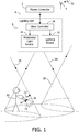
- Fig. 1 shows a first embodiment of a lighting system according to the invention. It comprises a master controller 2, which has a receiver (not shown) for receiving wireless transmissions. To exemplify only, it is assumed here that the receiver is suitable for receiving radio frequency (RF) transmissions. Therefore the receiver is connected to an antenna 4.
- the system further comprises at least one lighting unit 6.
- the master controller 2 is linked to the lighting units 6 by a link 8 for communication of data.
- the link 8 may be of any suitable type, wireless or not.
- a lighting unit 6 comprises a slave controller 10, which is connected to the link 8, a lighting source 12 and a modulated light source 14.
- the lighting source 12 is a light source for normal lighting and it can be controlled by the slave controller 10 to change a lighting property of the emitted light, such as intensity and color.
- the slave controller 10 can be controlled by the master controller 2 to control the lighting source 12 accordingly.
- the modulated light source 14 is, for example, an infrared light (IR) source.
- the modulated light source 14 is suitable to emit light which is different from modulated light emitted by other modulated light sources 14, such as by emitting at different instances (or time division emission), using different identifications to modulate with or using spread spectrum modulation.
- Such emissions of modulated light makes it possible to identify a modulated light source 14 emitting sensed modulated light and thereby the lighting source 12 of the same lighting unit 6.
- the modulated light may be modulated to carry data about the lighting unit 6, possibly in addition to an identification.
- Radiation patterns of the lighting source 12 and of the modulated light source 14 of the same lighting unit 6 are made to coincide substantially.
- the lighting system further comprises a remote control device 16.
- the remote control device 16 has a light-sensing part (or device), which has a light entrance 18 which provides a viewing area, indicated by a cone 19 in Fig. 1 , in which the sensing device can adequately sense modulated light.
- the remote control device 16 is a device which can be held by hand by a user 20.
- the remote control device 16 has wireless transmission means which is suitable for transmitting a signal which can be received by the receiver of the master controller 2, as indicated by arrows 22 near the antenna 4 and the remote control device 16.
- Fig. 1 shows an example of coinciding lighting patterns of the lighting source 12 and the modulated light source 14 of the same lighting unit 6, indicated by a cone 24 of a particular light intensity. Radiation patterns of other lighting units 6 are indicated by cones 26 and 28 of the same particular light intensity.
- an area or an object will be illuminated with different intensities by several lighting sources 12 directly or indirectly by reflection simultaneously. Therefore, if the user 20 points the remote control device 16 with its viewing area 19 to an object, such as a part of a floor or wall, and/or to one or more lighting units 6, a light sensor (not shown) of the remote control device 16 will sense modulated light which is emitted by modulated light sources 14 of different lighting units 6.
- a user 20 who wants to change illumination of an object needs to know which lighting sources 14 may contribute to a wanted illumination of the object and to what extend.
- the user would also need to know which lighting sources 12 are illuminating other areas or objects in order to maintain said illumination of other areas or objects by the same set or any other set of lighting sources 12. Obviously this will be very difficult and very time consuming for the user 20 to do.
- the invention provides a solution for this problem.
- different modulated light sources 14, indicated by L1, L2, L3, ... in fig. 2 may be controlled by the controller 10 or by the controllers 2 and 10 to emit light on different time instances t1, t2, t3, ..., respectively.
- the modulation may be a simple on or off control of the modulated light sources 14 on said instances.
- the modulation may also be carried out by allocating in advance a unique identification to each modulated light source and to on/off control the modulated light sources 14 on said instances in accordance with the identification code of the emitting modulated light source 14. This type of modulation is in accordance with a modulation technique known as "time-division multiplexing/multiplex access" (TDMA).
- TDMA time-division multiplexing/multiplex access
- the remote control device 16 If the user 20 operates the remote control device 16 to receive reflected light from an object, which is illuminated by a lighting unit 6, because of the substantially coinciding radiation patterns, the remote control device 16 will receive light from both the lighting source 12 and the modulated light source 14 of that lighting unit 6.
- the remote control device 16 is suitable to detect a change of intensity of modulated light it received, so that the remote control device or the master controller 2 can identify the modulated light source 14 having emitted the received modulated light with said change of intensity.
- the remote control device 16 is suitable to measure the intensity of modulated light received from any modulated light source 14, that is, with a greater resolution than offered by on/on control.
- the modulated light sources 14 may emit light constantly or during some period dependent on operation of the remote control device 16 by the user 20. At the time a modulated light source 14 generates and emits light the light has a maximum intensity. The modulated light will diverge according to a radiation pattern of the modulated light source 14. So will light emitted by the lighting device of the same lighting unit 6. Because the lighting source 12 and the modulating light source 14 have substantially coinciding radiation patterns for each lighting source 12 a light contribution to illumination of an object with respect to a maximum contribution level by said source 12 can be determined. Data containing values of intensity measurements on sensed modulated light are sent to the master controller 2. Data about a wanted illumination or illumination change indicated by the user 20 by operating the remote control device 16 is also sent to the master controller.
- the master controller 2 may control the lighting sources 12 dependent on data it receives from the remote control device 16 and (or inclusive) identifications of modulated light sources 14 which were responsible for the data about light intensities.
- the master controller 2 may carry out the control also dependent on properties of lighting sources 12, such as about lighting power and aging, acquired in advance or with each emission of light by a modulated light source 14.
- the control may also be made dependent on actual illumination of other areas or objects, so as to maintain such illumination and to achieve the wanted illumination by what ever combinations of lighting sources 12.
- Fig. 1 shows that the modulated light source 14 of a lighting unit 6 is connected to the slave controller 10 of that lighting unit 6. Therefore, the identification code of the lighting unit 6, in fact of its slave controller 10, could be used as identification code for the modulated light source 14 as well.
- the master controller 2 may control the slave controller 10 of different lighting units 6 to emit the modulated light at instances, which are determined by the master controller. In other cases the different modulated light sources 14 will emit modulated light at different, unrelated or random instances. The light must be modulated then with an identification code of the emitting modulated light source 14. Because collision of transmissions of modulated light by different modulated light sources 14 may occur then, the modulated light sources 14 are suitable to repeat their emissions at least once and with a random interval between transmissions and the remote control device 16 and the master controller 2 operate to detect modulated light and to process data there from received during at least a longest possible interval of the random interval between transmissions.
- the lighting system comprises a master controller 2 and apart there from one or more slave controllers 10.
- a master controller (or a controller in general) may be suitable to directly control lighting units 6 without requiring that the lighting units 6 contain a slave controller 10 or that a slave controller is used.
- a master controller (or a controller in general) may be suitable to directly control lighting units 6.
- any lighting source 12 can be of a type which allows modulation of the light emitted by it such that the modulation can not be perceived by humans, such as by very short intervals of on or off switching.
- a lighting source 12 and a modulated light source 14 of the same lighting unit 6 can be the same source, such as a light emitting diode (LED).
- LED light emitting diode
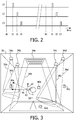
- Fig. 3 illustrates a second embodiment of a lighting system according to the invention.
- Fig. 3 shows a room 30 in which there are arranged lighting units 34a, 34b, 34c, 34d and 34e (34 in general).
- Lighting units 34a to 34d are illustrated to be spot lights, while lighting unit 34e is illustrated as to be a lighting unit for overall lighting of most part of the room (apart from lighting by reflection of light emitted by it).
- the lighting units 34a to 34e operate like the lighting unit 6 shown in Fig. 1 .
- a lighting unit 34 contains a lighting source, which operates as a modulated light source also.
- Light radiation patterns of lighting sources of the lighting units 34a to 34e are indicated by cones 36a to 36e of a particular light intensity, respectively.
- the system of the second embodiment of Fig. 3 further comprises a number of light-sensing devices 40a, 40b, 40c and 40d (40 in general), which are mounted in different locations in the room 30.
- Each light-sensing device 40 has a light sensitive area or a viewing area in which it can sense adequately light of a particular intensity or stronger. For clarity of the drawing the viewing areas of the sensing devices 40 are not shown in Fig. 3 .
- Different sensing devices 40 will sense light emitted by different lighting units 36 with different intensities.
- the system further comprises a remote control device 42 which can be held by hand by a user 20. Different from the first embodiment the remote control 42 does not sense light but, on command of the user, it emits light as a wireless control signal, which contains an activation command.
- a cone 44 indicates an intensity of the wireless control signal having an intensity, which is a minimum intensity to usably be received by a sensing device 40.
- the second lighting system illustrated by Fig. 3 may operate as follows. At some time a common controller switches on the lighting units 34 one by one to emit light with a maximum intensity. Each time a lighting unit 34 is switched on the common controller enables each sensing device 40 to sense if it received light from a lighting unit 34. This is a simple type of light modulation. The common controller may thereby ascertain an identification of a lighting unit 34 from which light is received. The sensing device 40 also measures the intensity of the light it receives and it communicates a value of the measured intensity to the common controller. The common controller stores the data thus acquired.
- the common controller can establish and holding an array containing for each sensing device 40 a sub array of pairs of an identification of each lighting unit 34 and a value of a highest intensity of light which can be sensed by the sensing device 40 from that lighting unit 34.
- the user 20 may direct the transmission cone 44 of the remote control device 42 to a sensing device 40 in an area of which he wants to change the lighting of. Then the user 20 operates the remote control device 42 to emit the wireless control signal containing an activation command.
- the sensing device 40 When the sensing device 40 receives the activation command it is communicated to the common controller, which is then enabled to use the data stored for said sensing device 40 for changing lighting of the area containing the sensing device 40 to a lighting effect wanted by the user, while maintaining lighting effects in areas containing other sensing devices 40.
- the user 20 may transmit commands to change the lighting provided by the lighting units 34 which, according to the stored data, are associated with the activated sensing device 40.
- the sensing devices 40 are always in a condition in which they can receive and process the activation command, so that a user may change between different areas containing different light-sensing devices 40 for selectively changing lighting effects in those areas.
- a light-sensing device 40 may measure intensities of light it receives from different lighting units each time the sensing device 40 receives the activation command. It is necessary then that the lighting sources 34 from which light is received are identified. This can be done in the same way as with the first embodiment of Fig. 1 , except that the sensing device 40 is now one fixed sensing device of several fixed sensing devices 40 instead of a sensing device of a handheld remote control device. Also, just like with the first embodiment, the lighting units 34 may have a lighting source and a modulated light source having substantially coinciding light radiation patterns. Measuring light intensities often than once has the advantage that the common controller may detect malfunction of lighting devices 34. It may even detect a rate of aging of each lighting unit 34. This is not possible with the first embodiment because of the unknown location of the remote control device 16 and therewith of its sensing device, which may sense light from any combination of lighting units and with different intensities on different times.
- Fig. 4 illustrates a third embodiment of a lighting system according to the invention.
- the system of Fig. 4 comprises an array 46 of lighting units 48.
- the array 46 may be suitable to lighten a room or it may be used to display all kinds of messages and images. It is an object to obtain wanted perceptions of light emitted by the array 46 in different locations. Therefore, in each of said locations a light-sensing device 52 is installed.
- Fig. 4 shows two sensing devices 52a and 52b only.
- each lighting unit 48 operates as a lighting source and as a modulated light source with, inherently, substantially coinciding light radiation patterns, which for some lighting units 48a, 48b, 48c, 48e and 48d are indicated by cones 50a, 50b, 50c, 50e 50d having a particular light intensity, respectively.
- Such lighting units 48 may be light emitting diodes (LED's).
- the system of Fig. 4 is applicable for any number and any size of lighting units and with or without separate modulated light sources. Therefore, the technique explained now for the third embodiment can be applied for the first and second embodiments also.
- the lighting units 48 may emit modulated light at the same time and continuously.
- a sensing device 52 senses light and by what intensity
- the modulated light emitted by a lighting unit 48 is modulated by using a spread spectrum technique.
- a spread spectrum technique is known as "code-division multiplexing/multiple access" (CDM or CDMA).
- CDMA code-division multiplexing/multiple access
- a unique code is allocated to each lighting unit 48, or to each group of one or more lighting units 48.
- the codes must be orthogonal. That is, a value of an autocorrelation of a code must be significant higher than a value of a cross-correlation of two different codes.
- a sensing device 52 is then able to discriminate between simultaneously transmissions of modulated light by different lighting units 48, so that the sensing device 52 can identify each of those lighting units 48 and the sensing device 52 can measure the intensity by which it received the modulated light from the identified lighting unit 48.
- the sensing device 52 transfers data containing an identification of the emitting lighting unit 48 and a value of the measured intensity of the modulated light received from the lighting unit 48 to a common controller, such as a controller 2 of the first embodiment. Having acquired such data from all sensing devices 48, the controller is able to control lighting units 48 of concern to change the intensity of their emitted light to thereby meet wanted light effects in areas comprising the sensing devices 48.
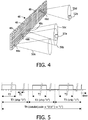
- Fig. 5 shows a time diagram for explaining the spread spectrum modulation technique for modulating light which is to be emitted by a lighting unit 48.
- the lighting units 48 have a maximum frequency by which their emitted light can be modulated.
- the inverse of the maximum frequency defines a minimum modulation interval.
- a clock signal is generated providing pulses having a cycle time which is greater than said minimum modulation interval. It is assumed here that the clock cycle time or period T1 (first interval).
- the intensity of light emitted by a lighting unit 48 on average during some time can be controlled by changing a duration of a second interval T2 during which the lighting unit 48 is switched on inside a constant third interval T3, that is, by controlling a duty cycle defined by a ratio of T2/T3.
- T3 is chosen to be short enough to make the on/off modulation not perceivable by a human.
- the light is modulated by the unique code of the emitting lighting unit 48.
- the code comprises a number of code bits, which in the field of CDMA are called "chips".
- the second interval T2 is located at two different locations inside the interval T3, dependent on which chip value must be presented.
- the interval T2 for representing a chip value "1" is delayed by 2*T1 with respect to the interval T2 for a chip representing a chip value "0".
- the lighting units 48 may, just like the lighting units 6, 34 of the first and second embodiments, transmit data, such as about properties of the lighting units, as well by proper modulation of the emitted light. With the third embodiment this can be done by using two codes per lighting unit 48, one for representing a "0" data bit (or channel bit) and one for representing a "1" data bit. For example, the two codes may be composed of the same chips, but in reversed order.
- a sensing device identifies all lighting units 6, 34, 48 from which the sensing device senses modulated light, it measures an intensity of the modulated light emitted by each identified lighting unit 6, 34, 48 and it communicates data about that to a common controller to let the controller control the lighting units 6, 34, 48, such as to obtain a wanted lighting or lighting effect in an area in which the sensing device is located.
- a lighting unit 6, 34, 48 may comprise a light source for emitting the modulated light, which is different from a light source for emitting not modulated light with a higher intensity for lighting of the area in a way that is perceptible for a human. In that case the lighting unit is made such that radiation patterns of the different light sources substantially coincide, as if the lighting unit comprised only one source.
Landscapes
- Engineering & Computer Science (AREA)
- Computer Networks & Wireless Communication (AREA)
- Circuit Arrangement For Electric Light Sources In General (AREA)
Priority Applications (1)
| Application Number | Priority Date | Filing Date | Title |
|---|---|---|---|
| EP06727972.9A EP1882394B1 (en) | 2005-04-22 | 2006-04-19 | Illumination control |
Applications Claiming Priority (5)
| Application Number | Priority Date | Filing Date | Title |
|---|---|---|---|
| EP05103292 | 2005-04-22 | ||
| EP05103279 | 2005-04-22 | ||
| EP05112561 | 2005-12-21 | ||
| PCT/IB2006/051211 WO2006111930A2 (en) | 2005-04-22 | 2006-04-19 | Illumination control |
| EP06727972.9A EP1882394B1 (en) | 2005-04-22 | 2006-04-19 | Illumination control |
Publications (2)
| Publication Number | Publication Date |
|---|---|
| EP1882394A2 EP1882394A2 (en) | 2008-01-30 |
| EP1882394B1 true EP1882394B1 (en) | 2018-09-19 |
Family
ID=37115543
Family Applications (1)
| Application Number | Title | Priority Date | Filing Date |
|---|---|---|---|
| EP06727972.9A Active EP1882394B1 (en) | 2005-04-22 | 2006-04-19 | Illumination control |
Country Status (5)
| Country | Link |
|---|---|
| US (1) | US7952292B2 (enExample) |
| EP (1) | EP1882394B1 (enExample) |
| JP (1) | JP5091114B2 (enExample) |
| CN (1) | CN101164382B (enExample) |
| WO (1) | WO2006111930A2 (enExample) |
Families Citing this family (103)
| Publication number | Priority date | Publication date | Assignee | Title |
|---|---|---|---|---|
| JP4625023B2 (ja) * | 2004-01-12 | 2011-02-02 | コーニンクレッカ フィリップス エレクトロニクス エヌ ヴィ | 占有検出による照明制御 |
| CN101529980B (zh) * | 2006-10-27 | 2011-04-13 | 皇家飞利浦电子股份有限公司 | 颜色受控光源以及对光源中的颜色生成进行控制的方法 |
| WO2008050293A1 (en) * | 2006-10-27 | 2008-05-02 | Koninklijke Philips Electronics N.V. | A color controlled light source and a method for controlling color generation in a light source |
| EP1931150A1 (en) | 2006-12-04 | 2008-06-11 | Koninklijke Philips Electronics N.V. | Image processing system for processing combined image data and depth data |
| WO2008093266A1 (en) | 2007-02-01 | 2008-08-07 | Koninklijke Philips Electronics N.V. | Controllable lighting system, pointing device therefore and method of lighting control |
| JP5062617B2 (ja) * | 2007-03-29 | 2012-10-31 | 学校法人同志社 | 照明システム |
| ATE541436T1 (de) | 2007-05-09 | 2012-01-15 | Koninkl Philips Electronics Nv | Verfahren und system zur steuerung eines beleuchtungssystems |
| CN101884248B (zh) * | 2007-06-18 | 2018-08-14 | 飞利浦灯具控股公司 | 方向可控的照明单元 |
| WO2009010916A2 (en) * | 2007-07-16 | 2009-01-22 | Koninklijke Philips Electronics N.V. | Driving a light source |
| DE602008003829D1 (de) * | 2007-07-18 | 2011-01-13 | Koninkl Philips Electronics Nv | Verfahren zur verarbeitung von licht in einer struktur und beleuchtungssystem |
| EP2179521B1 (en) | 2007-07-19 | 2016-09-07 | Philips Lighting Holding B.V. | Method, system and device for transmitting lighting device data |
| JP2011501347A (ja) * | 2007-10-12 | 2011-01-06 | コーニンクレッカ フィリップス エレクトロニクス エヌ ヴィ | レトロリフレクタを用いた符号化光の感知方法 |
| US8118447B2 (en) | 2007-12-20 | 2012-02-21 | Altair Engineering, Inc. | LED lighting apparatus with swivel connection |
| EP2277354A2 (en) * | 2008-01-17 | 2011-01-26 | Koninklijke Philips Electronics N.V. | Method and apparatus for light intensity control |
| JP5749932B2 (ja) * | 2008-01-23 | 2015-07-15 | コーニンクレッカ フィリップス エヌ ヴェ | Led型照明設備における一貫性のある色校正 |
| WO2009093161A1 (en) * | 2008-01-24 | 2009-07-30 | Koninklijke Philips Electronics N.V. | Remote control device for lighting systems |
| RU2523789C2 (ru) * | 2008-01-24 | 2014-07-27 | Конинклейке Филипс Электроникс Н.В. | Световая передача данных для конфигурации светочувствительных периферийных устройств |
| TW200950590A (en) | 2008-01-30 | 2009-12-01 | Koninkl Philips Electronics Nv | Lighting system and method for operating a lighting system |
| US8330379B2 (en) | 2008-02-12 | 2012-12-11 | Koninklijke Philips Electronics N.V. | Adaptive modulation and data embedding in light for advanced lighting control |
| EP2274958B1 (en) * | 2008-05-06 | 2017-09-13 | Philips Lighting Holding B.V. | Illumination system and method for processing light |
| US8594510B2 (en) | 2008-05-06 | 2013-11-26 | Koninklijke Philips N.V. | Light module, illumination system and method incorporating data in light emitted |
| JP5739803B2 (ja) | 2008-05-29 | 2015-06-24 | コーニンクレッカ フィリップス エヌ ヴェ | 光のセンサ・デバイス及び光の制御デバイス |
| CN105827332B (zh) * | 2008-06-11 | 2019-09-03 | 飞利浦灯具控股公司 | 用于照明系统的光接收器 |
| KR101644478B1 (ko) | 2008-09-26 | 2016-08-01 | 코닌클리케 필립스 엔.브이. | 복수의 광원의 자동 커미셔닝을 위한 시스템 및 방법 |
| US8324817B2 (en) | 2008-10-24 | 2012-12-04 | Ilumisys, Inc. | Light and light sensor |
| US7938562B2 (en) | 2008-10-24 | 2011-05-10 | Altair Engineering, Inc. | Lighting including integral communication apparatus |
| US8214084B2 (en) | 2008-10-24 | 2012-07-03 | Ilumisys, Inc. | Integration of LED lighting with building controls |
| US8901823B2 (en) | 2008-10-24 | 2014-12-02 | Ilumisys, Inc. | Light and light sensor |
| EP2342948A1 (de) * | 2008-10-29 | 2011-07-13 | Osram Gesellschaft mit beschränkter Haftung | Sensorelement mit einem lichtsensor, sender zur kommunikation mit sensorelement sowie beleuchtungssystem mit sensorelement |
| CN102246600B (zh) | 2008-12-09 | 2015-01-14 | 皇家飞利浦电子股份有限公司 | 用于自动地将设备集成到联网的系统中的系统和方法 |
| US9363855B2 (en) * | 2009-01-06 | 2016-06-07 | Koninklijke Philips N.V. | Control system for controlling one or more controllable devices sources and method for enabling such control |
| EP2417833B1 (en) | 2009-04-08 | 2018-09-05 | Philips Lighting Holding B.V. | Lighting device having status indication by modulated light |
| US8628198B2 (en) * | 2009-04-20 | 2014-01-14 | Lsi Industries, Inc. | Lighting techniques for wirelessly controlling lighting elements |
| CN102415020B (zh) * | 2009-04-28 | 2015-07-08 | 西门子公司 | 数据的光传输方法和装置 |
| TW201043088A (en) * | 2009-05-20 | 2010-12-01 | Pixart Imaging Inc | Light control system and control method thereof |
| ES2548149T3 (es) * | 2009-06-19 | 2015-10-14 | Koninklijke Philips N.V. | Sistema de iluminación y procedimiento con SNR mejorada |
| EP2446427B1 (en) | 2009-06-23 | 2013-05-01 | Koninklijke Philips Electronics N.V. | Method for selecting a controllable device |
| KR20120096923A (ko) * | 2009-06-30 | 2012-08-31 | 코닌클리즈케 필립스 일렉트로닉스 엔.브이. | 램프를 구동하기 위한 방법 및 디바이스 |
| RU2012103598A (ru) * | 2009-07-03 | 2013-08-10 | Конинклейке Филипс Электроникс Н.В. | Способ и система для асинхронной идентификации лампы |
| KR20120055715A (ko) | 2009-08-27 | 2012-05-31 | 코닌클리즈케 필립스 일렉트로닉스 엔.브이. | 광원 제어를 위한 인지 식별자 할당 |
| JP5698751B2 (ja) * | 2009-09-29 | 2015-04-08 | コーニンクレッカ フィリップス エヌ ヴェ | 照明システム及び照明システムを制御する方法 |
| EP2522203B1 (en) | 2010-01-06 | 2020-04-01 | Signify Holding B.V. | Adaptable lighting system |
| CN102792779B (zh) * | 2010-03-19 | 2016-07-13 | 皇家飞利浦电子股份有限公司 | 光源选择 |
| US8540401B2 (en) | 2010-03-26 | 2013-09-24 | Ilumisys, Inc. | LED bulb with internal heat dissipating structures |
| CA2792940A1 (en) | 2010-03-26 | 2011-09-19 | Ilumisys, Inc. | Led light with thermoelectric generator |
| US8523394B2 (en) | 2010-10-29 | 2013-09-03 | Ilumisys, Inc. | Mechanisms for reducing risk of shock during installation of light tube |
| BR112013016413A2 (pt) * | 2010-12-29 | 2019-09-24 | Koninl Philips Electronics Nv | dispositivo de iluminação, sistema de iluminação e método de um sistema de iluminação |
| CN102164436A (zh) * | 2011-02-22 | 2011-08-24 | 华东理工大学 | 基于可见光通信接收机的自适应照明系统 |
| EP2503852A1 (en) * | 2011-03-22 | 2012-09-26 | Koninklijke Philips Electronics N.V. | Light detection system and method |
| EP2700286B1 (en) * | 2011-04-21 | 2015-06-10 | Koninklijke Philips N.V. | An electric light and daylight control system with a dual-mode light sensor |
| US9103540B2 (en) | 2011-04-21 | 2015-08-11 | Optalite Technologies, Inc. | High efficiency LED lighting system with thermal diffusion |
| US9418115B2 (en) | 2011-07-26 | 2016-08-16 | Abl Ip Holding Llc | Location-based mobile services and applications |
| US8416290B2 (en) | 2011-07-26 | 2013-04-09 | ByteLight, Inc. | Method and system for digital pulse recognition demodulation |
| US9287976B2 (en) | 2011-07-26 | 2016-03-15 | Abl Ip Holding Llc | Independent beacon based light position system |
| US8866391B2 (en) | 2011-07-26 | 2014-10-21 | ByteLight, Inc. | Self identifying modulated light source |
| US9787397B2 (en) | 2011-07-26 | 2017-10-10 | Abl Ip Holding Llc | Self identifying modulated light source |
| US9723676B2 (en) | 2011-07-26 | 2017-08-01 | Abl Ip Holding Llc | Method and system for modifying a beacon light source for use in a light based positioning system |
| US8334898B1 (en) | 2011-07-26 | 2012-12-18 | ByteLight, Inc. | Method and system for configuring an imaging device for the reception of digital pulse recognition information |
| US9444547B2 (en) | 2011-07-26 | 2016-09-13 | Abl Ip Holding Llc | Self-identifying one-way authentication method using optical signals |
| WO2013068866A1 (en) | 2011-11-10 | 2013-05-16 | Koninklijke Philips Electronics N.V. | Presence detection using split beam luminaire |
| EP2751519B1 (en) | 2011-11-10 | 2021-04-14 | Signify Holding B.V. | Distance estimation using split beam luminaire |
| JP6087941B2 (ja) * | 2011-11-15 | 2017-03-01 | フィリップス ライティング ホールディング ビー ヴィ | 符号化光の送信及び受信方法 |
| US8842009B2 (en) | 2012-06-07 | 2014-09-23 | Mojo Labs, Inc. | Multiple light sensor multiple light fixture control |
| US8749145B2 (en) * | 2011-12-05 | 2014-06-10 | Mojo Labs, Inc. | Determination of lighting contributions for light fixtures using optical bursts |
| US8749146B2 (en) | 2011-12-05 | 2014-06-10 | Mojo Labs, Inc. | Auto commissioning of light fixture using optical bursts |
| JP2013120623A (ja) | 2011-12-06 | 2013-06-17 | Panasonic Corp | 照明システム |
| CN104041191B (zh) * | 2012-01-17 | 2016-12-07 | 皇家飞利浦有限公司 | 使用远程控制的可见光通信照明设备、远程控制单元、系统及方法 |
| RU2632248C2 (ru) * | 2012-05-15 | 2017-10-03 | Филипс Лайтинг Холдинг Б.В. | Управление устройствами освещения |
| US9271367B2 (en) | 2012-07-09 | 2016-02-23 | Ilumisys, Inc. | System and method for controlling operation of an LED-based light |
| CN102970796B (zh) * | 2012-11-15 | 2015-10-28 | 珠海雷特电子科技有限公司 | 一种led控制器无线分区系统 |
| CN103052209B (zh) * | 2012-11-15 | 2015-11-18 | 珠海雷特电子科技有限公司 | 一种led照明无线同步系统 |
| CN103037581B (zh) * | 2012-12-14 | 2016-02-03 | 北京时代凌宇科技有限公司 | 一种无线灯控系统及灯控方法 |
| US9285084B2 (en) | 2013-03-14 | 2016-03-15 | Ilumisys, Inc. | Diffusers for LED-based lights |
| US8699887B1 (en) | 2013-03-14 | 2014-04-15 | Bret Rothenberg | Methods and systems for encoding and decoding visible light with data and illumination capability |
| US9804024B2 (en) | 2013-03-14 | 2017-10-31 | Mojo Labs, Inc. | Light measurement and/or control translation for daylighting |
| US9705600B1 (en) | 2013-06-05 | 2017-07-11 | Abl Ip Holding Llc | Method and system for optical communication |
| US9496955B2 (en) | 2013-09-19 | 2016-11-15 | eocys, LLC | Devices and methods to produce and receive an encoded light signature |
| EP3053415B1 (en) * | 2013-10-04 | 2021-08-11 | Signify Holding B.V. | Methods and devices for projection of lighting effects carrying information |
| US9267650B2 (en) | 2013-10-09 | 2016-02-23 | Ilumisys, Inc. | Lens for an LED-based light |
| CA2931526C (en) | 2013-11-25 | 2022-04-19 | Abl Ip Holding Llc | System and method for communication with a mobile device via a positioning system including rf communication devices and modulated beacon light sources |
| US20150173154A1 (en) * | 2013-12-17 | 2015-06-18 | Nxp B.V. | Commissioning method and apparatus |
| JP6416915B2 (ja) * | 2014-01-08 | 2018-10-31 | フィリップス ライティング ホールディング ビー ヴィ | 検出された照明の変化に基づいて照明を制御するための方法及び機器 |
| KR20160111975A (ko) | 2014-01-22 | 2016-09-27 | 일루미시스, 인크. | 어드레스된 led들을 갖는 led 기반 조명 |
| DE102014202445A1 (de) * | 2014-02-11 | 2015-08-13 | Zumtobel Lighting Gmbh | Beleuchtungssystem und Verfahren zum Betrieb eines Beleuchtungssystems mit integriertem Sicherheitskonzept |
| US9386667B2 (en) | 2014-02-26 | 2016-07-05 | Blaine Clifford Readler | Encoded light-activated illumination |
| US9510400B2 (en) | 2014-05-13 | 2016-11-29 | Ilumisys, Inc. | User input systems for an LED-based light |
| JP6405820B2 (ja) * | 2014-09-17 | 2018-10-17 | 富士通株式会社 | 信号伝送装置、信号伝送方法および信号伝送プログラム |
| US10070496B2 (en) | 2015-03-30 | 2018-09-04 | Mojo Labs, Inc. | Task to wall color control |
| US10161568B2 (en) | 2015-06-01 | 2018-12-25 | Ilumisys, Inc. | LED-based light with canted outer walls |
| WO2017016822A1 (en) * | 2015-07-27 | 2017-02-02 | Philips Lighting Holding B.V. | Light emitting device for generating light with embedded information |
| US20170139582A1 (en) * | 2015-11-13 | 2017-05-18 | General Electric Company | Method and system for controlling an illumination device and related lighting system |
| US9544957B1 (en) * | 2015-12-02 | 2017-01-10 | Paragon Semiconductor Lighting Technology Co., Ltd. | Illumination device |
| WO2018200685A2 (en) | 2017-04-27 | 2018-11-01 | Ecosense Lighting Inc. | Methods and systems for an automated design, fulfillment, deployment and operation platform for lighting installations |
| CN109479358B (zh) * | 2016-06-27 | 2021-06-22 | 昕诺飞控股有限公司 | 多灯照明器和操作它的方法 |
| CN106228794A (zh) * | 2016-07-18 | 2016-12-14 | 徐承柬 | 一种房间内电源开关控制方法及系统 |
| CN106376153A (zh) * | 2016-08-26 | 2017-02-01 | 苏州亿凌泰克智能科技有限公司 | 一种光照系统 |
| DE102016217594A1 (de) * | 2016-09-15 | 2018-03-15 | Zumtobel Lighting Gmbh | Leuchtensystem |
| US10293746B2 (en) * | 2017-01-03 | 2019-05-21 | HELLA GmbH & Co. KGaA | Method for operating an interior lighting device for a motor vehicle, interior lighting device for a motor vehicle and motor vehicle |
| GB201701209D0 (en) * | 2017-01-24 | 2017-03-08 | Purelifi Ltd | Optical wireless communication system |
| US10916165B2 (en) * | 2017-02-27 | 2021-02-09 | Research Foundation Of The City University Of New York | Cyber-enabled displays for intelligent transportation systems |
| TWI647976B (zh) * | 2017-08-24 | 2019-01-11 | 財團法人工業技術研究院 | 照明控制系統及照明控制方法 |
| CN108966462B (zh) * | 2018-08-14 | 2020-01-14 | 深圳市银河风云网络系统股份有限公司 | 灯具物理位置确定方法及装置 |
| US11175006B2 (en) | 2018-09-04 | 2021-11-16 | Udayan Kanade | Adaptive lighting system for even illumination |
Family Cites Families (14)
| Publication number | Priority date | Publication date | Assignee | Title |
|---|---|---|---|---|
| US4779266A (en) | 1986-03-10 | 1988-10-18 | Bell Communications Research, Inc. | Encoding and decoding for code division multiple access communication systems |
| JPS6430347A (en) * | 1987-07-27 | 1989-02-01 | Nippon Telegraph & Telephone | Light self routing channel |
| CN2211682Y (zh) * | 1994-11-10 | 1995-11-01 | 赵伟庭 | 一种数码电力线载波照明开关 |
| JPH09306673A (ja) * | 1996-05-15 | 1997-11-28 | Matsushita Electric Works Ltd | 照明装置 |
| US6271815B1 (en) | 1998-02-20 | 2001-08-07 | University Of Hong Kong | Handy information display system |
| US6445369B1 (en) | 1998-02-20 | 2002-09-03 | The University Of Hong Kong | Light emitting diode dot matrix display system with audio output |
| JPH11331086A (ja) | 1998-05-20 | 1999-11-30 | Teratec:Kk | 光信号伝送システム |
| JP2000275318A (ja) * | 1999-03-29 | 2000-10-06 | Hitachi Ltd | ホームネットワークシステムおよびその端末装置 |
| US6333605B1 (en) * | 1999-11-02 | 2001-12-25 | Energy Savings, Inc. | Light modulating electronic ballast |
| JP2001176676A (ja) | 1999-12-15 | 2001-06-29 | Matsushita Electric Works Ltd | 照明装置 |
| WO2002013490A2 (en) * | 2000-08-07 | 2002-02-14 | Color Kinetics Incorporated | Automatic configuration systems and methods for lighting and other applications |
| US6655817B2 (en) * | 2001-12-10 | 2003-12-02 | Tom Devlin | Remote controlled lighting apparatus and method |
| JP2004297295A (ja) * | 2003-03-26 | 2004-10-21 | Global Com:Kk | 照明光通信システム及び照明装置、照明光源 |
| ATE357125T1 (de) * | 2002-12-19 | 2007-04-15 | Koninkl Philips Electronics Nv | Konfigurationsverfahren für ein drahtlos gesteuertes beleuchtungssystem |
-
2006
- 2006-04-19 CN CN2006800135549A patent/CN101164382B/zh active Active
- 2006-04-19 WO PCT/IB2006/051211 patent/WO2006111930A2/en not_active Ceased
- 2006-04-19 JP JP2008507248A patent/JP5091114B2/ja active Active
- 2006-04-19 US US11/912,166 patent/US7952292B2/en active Active
- 2006-04-19 EP EP06727972.9A patent/EP1882394B1/en active Active
Non-Patent Citations (1)
| Title |
|---|
| None * |
Also Published As
| Publication number | Publication date |
|---|---|
| WO2006111930A2 (en) | 2006-10-26 |
| CN101164382B (zh) | 2012-12-12 |
| WO2006111930A3 (en) | 2007-04-26 |
| US20080185969A1 (en) | 2008-08-07 |
| JP2008537306A (ja) | 2008-09-11 |
| US7952292B2 (en) | 2011-05-31 |
| EP1882394A2 (en) | 2008-01-30 |
| JP5091114B2 (ja) | 2012-12-05 |
| CN101164382A (zh) | 2008-04-16 |
Similar Documents
| Publication | Publication Date | Title |
|---|---|---|
| EP1882394B1 (en) | Illumination control | |
| US8643286B2 (en) | Illumination system and method for processing light | |
| US8093817B2 (en) | Method and system for lighting control | |
| US8692656B2 (en) | Intrinsic flux sensing | |
| KR101614000B1 (ko) | 코딩 조명 시스템에서의 효율적인 어드레스 할당 | |
| EP2443911B1 (en) | Illumination system and method with improved snr | |
| US8981912B2 (en) | Pushbits for semi-synchronized pointing | |
| CN105827332B (zh) | 用于照明系统的光接收器 | |
| US20080197782A1 (en) | Method and System for Lighting Control | |
| EP1915890B1 (en) | Selective control of lighting devices | |
| US12309896B2 (en) | Lighting system and control method of said system | |
| WO2009060373A1 (en) | A luminaire, a control device and a method for controlling a luminaire |
Legal Events
| Date | Code | Title | Description |
|---|---|---|---|
| PUAI | Public reference made under article 153(3) epc to a published international application that has entered the european phase |
Free format text: ORIGINAL CODE: 0009012 |
|
| 17P | Request for examination filed |
Effective date: 20071122 |
|
| AK | Designated contracting states |
Kind code of ref document: A2 Designated state(s): AT BE BG CH CY CZ DE DK EE ES FI FR GB GR HU IE IS IT LI LT LU LV MC NL PL PT RO SE SI SK TR |
|
| DAX | Request for extension of the european patent (deleted) | ||
| 17Q | First examination report despatched |
Effective date: 20080918 |
|
| RAP1 | Party data changed (applicant data changed or rights of an application transferred) |
Owner name: KONINKLIJKE PHILIPS N.V. |
|
| RAP1 | Party data changed (applicant data changed or rights of an application transferred) |
Owner name: PHILIPS LIGHTING HOLDING B.V. |
|
| GRAP | Despatch of communication of intention to grant a patent |
Free format text: ORIGINAL CODE: EPIDOSNIGR1 |
|
| STAA | Information on the status of an ep patent application or granted ep patent |
Free format text: STATUS: GRANT OF PATENT IS INTENDED |
|
| INTG | Intention to grant announced |
Effective date: 20180412 |
|
| GRAS | Grant fee paid |
Free format text: ORIGINAL CODE: EPIDOSNIGR3 |
|
| GRAA | (expected) grant |
Free format text: ORIGINAL CODE: 0009210 |
|
| STAA | Information on the status of an ep patent application or granted ep patent |
Free format text: STATUS: THE PATENT HAS BEEN GRANTED |
|
| AK | Designated contracting states |
Kind code of ref document: B1 Designated state(s): AT BE BG CH CY CZ DE DK EE ES FI FR GB GR HU IE IS IT LI LT LU LV MC NL PL PT RO SE SI SK TR |
|
| REG | Reference to a national code |
Ref country code: GB Ref legal event code: FG4D |
|
| REG | Reference to a national code |
Ref country code: CH Ref legal event code: EP |
|
| REG | Reference to a national code |
Ref country code: DE Ref legal event code: R096 Ref document number: 602006056367 Country of ref document: DE |
|
| REG | Reference to a national code |
Ref country code: AT Ref legal event code: REF Ref document number: 1044861 Country of ref document: AT Kind code of ref document: T Effective date: 20181015 |
|
| REG | Reference to a national code |
Ref country code: IE Ref legal event code: FG4D |
|
| RAP2 | Party data changed (patent owner data changed or rights of a patent transferred) |
Owner name: PHILIPS LIGHTING HOLDING B.V. |
|
| REG | Reference to a national code |
Ref country code: NL Ref legal event code: MP Effective date: 20180919 |
|
| REG | Reference to a national code |
Ref country code: SE Ref legal event code: TRGR |
|
| PG25 | Lapsed in a contracting state [announced via postgrant information from national office to epo] |
Ref country code: FI Free format text: LAPSE BECAUSE OF FAILURE TO SUBMIT A TRANSLATION OF THE DESCRIPTION OR TO PAY THE FEE WITHIN THE PRESCRIBED TIME-LIMIT Effective date: 20180919 Ref country code: GR Free format text: LAPSE BECAUSE OF FAILURE TO SUBMIT A TRANSLATION OF THE DESCRIPTION OR TO PAY THE FEE WITHIN THE PRESCRIBED TIME-LIMIT Effective date: 20181220 Ref country code: BG Free format text: LAPSE BECAUSE OF FAILURE TO SUBMIT A TRANSLATION OF THE DESCRIPTION OR TO PAY THE FEE WITHIN THE PRESCRIBED TIME-LIMIT Effective date: 20181219 Ref country code: LT Free format text: LAPSE BECAUSE OF FAILURE TO SUBMIT A TRANSLATION OF THE DESCRIPTION OR TO PAY THE FEE WITHIN THE PRESCRIBED TIME-LIMIT Effective date: 20180919 |
|
| REG | Reference to a national code |
Ref country code: LT Ref legal event code: MG4D |
|
| PG25 | Lapsed in a contracting state [announced via postgrant information from national office to epo] |
Ref country code: LV Free format text: LAPSE BECAUSE OF FAILURE TO SUBMIT A TRANSLATION OF THE DESCRIPTION OR TO PAY THE FEE WITHIN THE PRESCRIBED TIME-LIMIT Effective date: 20180919 |
|
| RAP2 | Party data changed (patent owner data changed or rights of a patent transferred) |
Owner name: SIGNIFY HOLDING B.V. |
|
| REG | Reference to a national code |
Ref country code: AT Ref legal event code: MK05 Ref document number: 1044861 Country of ref document: AT Kind code of ref document: T Effective date: 20180919 |
|
| PG25 | Lapsed in a contracting state [announced via postgrant information from national office to epo] |
Ref country code: ES Free format text: LAPSE BECAUSE OF FAILURE TO SUBMIT A TRANSLATION OF THE DESCRIPTION OR TO PAY THE FEE WITHIN THE PRESCRIBED TIME-LIMIT Effective date: 20180919 Ref country code: NL Free format text: LAPSE BECAUSE OF FAILURE TO SUBMIT A TRANSLATION OF THE DESCRIPTION OR TO PAY THE FEE WITHIN THE PRESCRIBED TIME-LIMIT Effective date: 20180919 Ref country code: AT Free format text: LAPSE BECAUSE OF FAILURE TO SUBMIT A TRANSLATION OF THE DESCRIPTION OR TO PAY THE FEE WITHIN THE PRESCRIBED TIME-LIMIT Effective date: 20180919 Ref country code: CZ Free format text: LAPSE BECAUSE OF FAILURE TO SUBMIT A TRANSLATION OF THE DESCRIPTION OR TO PAY THE FEE WITHIN THE PRESCRIBED TIME-LIMIT Effective date: 20180919 Ref country code: EE Free format text: LAPSE BECAUSE OF FAILURE TO SUBMIT A TRANSLATION OF THE DESCRIPTION OR TO PAY THE FEE WITHIN THE PRESCRIBED TIME-LIMIT Effective date: 20180919 Ref country code: RO Free format text: LAPSE BECAUSE OF FAILURE TO SUBMIT A TRANSLATION OF THE DESCRIPTION OR TO PAY THE FEE WITHIN THE PRESCRIBED TIME-LIMIT Effective date: 20180919 Ref country code: PL Free format text: LAPSE BECAUSE OF FAILURE TO SUBMIT A TRANSLATION OF THE DESCRIPTION OR TO PAY THE FEE WITHIN THE PRESCRIBED TIME-LIMIT Effective date: 20180919 Ref country code: IS Free format text: LAPSE BECAUSE OF FAILURE TO SUBMIT A TRANSLATION OF THE DESCRIPTION OR TO PAY THE FEE WITHIN THE PRESCRIBED TIME-LIMIT Effective date: 20190119 |
|
| PG25 | Lapsed in a contracting state [announced via postgrant information from national office to epo] |
Ref country code: PT Free format text: LAPSE BECAUSE OF FAILURE TO SUBMIT A TRANSLATION OF THE DESCRIPTION OR TO PAY THE FEE WITHIN THE PRESCRIBED TIME-LIMIT Effective date: 20190119 Ref country code: SK Free format text: LAPSE BECAUSE OF FAILURE TO SUBMIT A TRANSLATION OF THE DESCRIPTION OR TO PAY THE FEE WITHIN THE PRESCRIBED TIME-LIMIT Effective date: 20180919 |
|
| REG | Reference to a national code |
Ref country code: DE Ref legal event code: R097 Ref document number: 602006056367 Country of ref document: DE |
|
| PLBE | No opposition filed within time limit |
Free format text: ORIGINAL CODE: 0009261 |
|
| STAA | Information on the status of an ep patent application or granted ep patent |
Free format text: STATUS: NO OPPOSITION FILED WITHIN TIME LIMIT |
|
| PG25 | Lapsed in a contracting state [announced via postgrant information from national office to epo] |
Ref country code: DK Free format text: LAPSE BECAUSE OF FAILURE TO SUBMIT A TRANSLATION OF THE DESCRIPTION OR TO PAY THE FEE WITHIN THE PRESCRIBED TIME-LIMIT Effective date: 20180919 |
|
| 26N | No opposition filed |
Effective date: 20190620 |
|
| PG25 | Lapsed in a contracting state [announced via postgrant information from national office to epo] |
Ref country code: SI Free format text: LAPSE BECAUSE OF FAILURE TO SUBMIT A TRANSLATION OF THE DESCRIPTION OR TO PAY THE FEE WITHIN THE PRESCRIBED TIME-LIMIT Effective date: 20180919 |
|
| REG | Reference to a national code |
Ref country code: CH Ref legal event code: PL |
|
| REG | Reference to a national code |
Ref country code: BE Ref legal event code: MM Effective date: 20190430 |
|
| PG25 | Lapsed in a contracting state [announced via postgrant information from national office to epo] |
Ref country code: LU Free format text: LAPSE BECAUSE OF NON-PAYMENT OF DUE FEES Effective date: 20190419 Ref country code: MC Free format text: LAPSE BECAUSE OF FAILURE TO SUBMIT A TRANSLATION OF THE DESCRIPTION OR TO PAY THE FEE WITHIN THE PRESCRIBED TIME-LIMIT Effective date: 20180919 |
|
| PG25 | Lapsed in a contracting state [announced via postgrant information from national office to epo] |
Ref country code: LI Free format text: LAPSE BECAUSE OF NON-PAYMENT OF DUE FEES Effective date: 20190430 Ref country code: CH Free format text: LAPSE BECAUSE OF NON-PAYMENT OF DUE FEES Effective date: 20190430 |
|
| PG25 | Lapsed in a contracting state [announced via postgrant information from national office to epo] |
Ref country code: BE Free format text: LAPSE BECAUSE OF NON-PAYMENT OF DUE FEES Effective date: 20190430 |
|
| PG25 | Lapsed in a contracting state [announced via postgrant information from national office to epo] |
Ref country code: TR Free format text: LAPSE BECAUSE OF FAILURE TO SUBMIT A TRANSLATION OF THE DESCRIPTION OR TO PAY THE FEE WITHIN THE PRESCRIBED TIME-LIMIT Effective date: 20180919 |
|
| PG25 | Lapsed in a contracting state [announced via postgrant information from national office to epo] |
Ref country code: IE Free format text: LAPSE BECAUSE OF NON-PAYMENT OF DUE FEES Effective date: 20190419 |
|
| REG | Reference to a national code |
Ref country code: DE Ref legal event code: R081 Ref document number: 602006056367 Country of ref document: DE Owner name: SIGNIFY HOLDING B.V., NL Free format text: FORMER OWNER: PHILIPS LIGHTING HOLDING B.V., EINDHOVEN, NL |
|
| PG25 | Lapsed in a contracting state [announced via postgrant information from national office to epo] |
Ref country code: CY Free format text: LAPSE BECAUSE OF FAILURE TO SUBMIT A TRANSLATION OF THE DESCRIPTION OR TO PAY THE FEE WITHIN THE PRESCRIBED TIME-LIMIT Effective date: 20180919 |
|
| PG25 | Lapsed in a contracting state [announced via postgrant information from national office to epo] |
Ref country code: HU Free format text: LAPSE BECAUSE OF FAILURE TO SUBMIT A TRANSLATION OF THE DESCRIPTION OR TO PAY THE FEE WITHIN THE PRESCRIBED TIME-LIMIT; INVALID AB INITIO Effective date: 20060419 |
|
| P01 | Opt-out of the competence of the unified patent court (upc) registered |
Effective date: 20230421 |
|
| PGFP | Annual fee paid to national office [announced via postgrant information from national office to epo] |
Ref country code: DE Payment date: 20240627 Year of fee payment: 19 |
|
| PGFP | Annual fee paid to national office [announced via postgrant information from national office to epo] |
Ref country code: GB Payment date: 20250422 Year of fee payment: 20 |
|
| PGFP | Annual fee paid to national office [announced via postgrant information from national office to epo] |
Ref country code: IT Payment date: 20250422 Year of fee payment: 20 |
|
| PGFP | Annual fee paid to national office [announced via postgrant information from national office to epo] |
Ref country code: FR Payment date: 20250424 Year of fee payment: 20 |
|
| PGFP | Annual fee paid to national office [announced via postgrant information from national office to epo] |
Ref country code: SE Payment date: 20250424 Year of fee payment: 20 |
|
| REG | Reference to a national code |
Ref country code: DE Ref legal event code: R119 Ref document number: 602006056367 Country of ref document: DE |
|
| PG25 | Lapsed in a contracting state [announced via postgrant information from national office to epo] |
Ref country code: DE Free format text: LAPSE BECAUSE OF NON-PAYMENT OF DUE FEES Effective date: 20251104 |