EP1882109B1 - Anneau de roulement destine en particulier a des roulements soumis a de fortes contraintes dans des reacteurs d'avions, et procede de realisation - Google Patents
Anneau de roulement destine en particulier a des roulements soumis a de fortes contraintes dans des reacteurs d'avions, et procede de realisation Download PDFInfo
- Publication number
- EP1882109B1 EP1882109B1 EP06722842A EP06722842A EP1882109B1 EP 1882109 B1 EP1882109 B1 EP 1882109B1 EP 06722842 A EP06722842 A EP 06722842A EP 06722842 A EP06722842 A EP 06722842A EP 1882109 B1 EP1882109 B1 EP 1882109B1
- Authority
- EP
- European Patent Office
- Prior art keywords
- bearing ring
- rolling bearing
- steel
- raceway
- rolling
- Prior art date
- Legal status (The legal status is an assumption and is not a legal conclusion. Google has not performed a legal analysis and makes no representation as to the accuracy of the status listed.)
- Expired - Fee Related
Links
Images


Classifications
-
- F—MECHANICAL ENGINEERING; LIGHTING; HEATING; WEAPONS; BLASTING
- F16—ENGINEERING ELEMENTS AND UNITS; GENERAL MEASURES FOR PRODUCING AND MAINTAINING EFFECTIVE FUNCTIONING OF MACHINES OR INSTALLATIONS; THERMAL INSULATION IN GENERAL
- F16C—SHAFTS; FLEXIBLE SHAFTS; ELEMENTS OR CRANKSHAFT MECHANISMS; ROTARY BODIES OTHER THAN GEARING ELEMENTS; BEARINGS
- F16C33/00—Parts of bearings; Special methods for making bearings or parts thereof
- F16C33/30—Parts of ball or roller bearings
- F16C33/58—Raceways; Race rings
- F16C33/64—Special methods of manufacture
-
- F—MECHANICAL ENGINEERING; LIGHTING; HEATING; WEAPONS; BLASTING
- F16—ENGINEERING ELEMENTS AND UNITS; GENERAL MEASURES FOR PRODUCING AND MAINTAINING EFFECTIVE FUNCTIONING OF MACHINES OR INSTALLATIONS; THERMAL INSULATION IN GENERAL
- F16C—SHAFTS; FLEXIBLE SHAFTS; ELEMENTS OR CRANKSHAFT MECHANISMS; ROTARY BODIES OTHER THAN GEARING ELEMENTS; BEARINGS
- F16C33/00—Parts of bearings; Special methods for making bearings or parts thereof
- F16C33/30—Parts of ball or roller bearings
- F16C33/58—Raceways; Race rings
- F16C33/60—Raceways; Race rings divided or split, e.g. comprising two juxtaposed rings
-
- F—MECHANICAL ENGINEERING; LIGHTING; HEATING; WEAPONS; BLASTING
- F16—ENGINEERING ELEMENTS AND UNITS; GENERAL MEASURES FOR PRODUCING AND MAINTAINING EFFECTIVE FUNCTIONING OF MACHINES OR INSTALLATIONS; THERMAL INSULATION IN GENERAL
- F16C—SHAFTS; FLEXIBLE SHAFTS; ELEMENTS OR CRANKSHAFT MECHANISMS; ROTARY BODIES OTHER THAN GEARING ELEMENTS; BEARINGS
- F16C33/00—Parts of bearings; Special methods for making bearings or parts thereof
- F16C33/30—Parts of ball or roller bearings
- F16C33/58—Raceways; Race rings
- F16C33/62—Selection of substances
-
- F—MECHANICAL ENGINEERING; LIGHTING; HEATING; WEAPONS; BLASTING
- F16—ENGINEERING ELEMENTS AND UNITS; GENERAL MEASURES FOR PRODUCING AND MAINTAINING EFFECTIVE FUNCTIONING OF MACHINES OR INSTALLATIONS; THERMAL INSULATION IN GENERAL
- F16C—SHAFTS; FLEXIBLE SHAFTS; ELEMENTS OR CRANKSHAFT MECHANISMS; ROTARY BODIES OTHER THAN GEARING ELEMENTS; BEARINGS
- F16C19/00—Bearings with rolling contact, for exclusively rotary movement
- F16C19/02—Bearings with rolling contact, for exclusively rotary movement with bearing balls essentially of the same size in one or more circular rows
- F16C19/04—Bearings with rolling contact, for exclusively rotary movement with bearing balls essentially of the same size in one or more circular rows for radial load mainly
- F16C19/06—Bearings with rolling contact, for exclusively rotary movement with bearing balls essentially of the same size in one or more circular rows for radial load mainly with a single row or balls
-
- F—MECHANICAL ENGINEERING; LIGHTING; HEATING; WEAPONS; BLASTING
- F16—ENGINEERING ELEMENTS AND UNITS; GENERAL MEASURES FOR PRODUCING AND MAINTAINING EFFECTIVE FUNCTIONING OF MACHINES OR INSTALLATIONS; THERMAL INSULATION IN GENERAL
- F16C—SHAFTS; FLEXIBLE SHAFTS; ELEMENTS OR CRANKSHAFT MECHANISMS; ROTARY BODIES OTHER THAN GEARING ELEMENTS; BEARINGS
- F16C2226/00—Joining parts; Fastening; Assembling or mounting parts
- F16C2226/30—Material joints
- F16C2226/36—Material joints by welding
-
- Y—GENERAL TAGGING OF NEW TECHNOLOGICAL DEVELOPMENTS; GENERAL TAGGING OF CROSS-SECTIONAL TECHNOLOGIES SPANNING OVER SEVERAL SECTIONS OF THE IPC; TECHNICAL SUBJECTS COVERED BY FORMER USPC CROSS-REFERENCE ART COLLECTIONS [XRACs] AND DIGESTS
- Y10—TECHNICAL SUBJECTS COVERED BY FORMER USPC
- Y10T—TECHNICAL SUBJECTS COVERED BY FORMER US CLASSIFICATION
- Y10T29/00—Metal working
- Y10T29/49—Method of mechanical manufacture
- Y10T29/49636—Process for making bearing or component thereof
- Y10T29/49643—Rotary bearing
- Y10T29/49679—Anti-friction bearing or component thereof
- Y10T29/49689—Race making
Definitions
- the invention relates to a rolling bearing ring according to the preamble forming features of claim 1, which is particularly suitable for highly stressed rolling bearings in aircraft engines, and a method for producing such a rolling bearing ring.
- the rolling bearing rings each consist of a solid composite of two layers of different metallic materials, that is, the range of the raceway for the rolling elements of a steel with very high hardness and wear resistance and the core portion of the rolling bearing ring of a steel with high toughness form.
- Such a rolling bearing ring of a Vebundtechnikstoff is for example from the DE 27 45 527 A1 previously known.
- This rolling bearing ring consists of a raceway for the rolling elements forming the first ring of a chromium alloyed bearing steel and a core of the rolling bearing ring forming second ring of a corrosion-resistant steel with a low carbon content.
- These two volumes exactly to each other formed rings are plugged into each other for connection with each other concentrically and radially deformed until filling a chamber corresponding to the dimensions of the bearing ring with simultaneous formation of the raceways for the rolling elements by roll forming.
- the rings are subjected to a thermal treatment and firmly joined together by shrinking and finally finished by over-turning and grinding.
- a disadvantage of this rolling bearing of a composite material is that the two rings of different materials together tangentially, radially and axially deformed by rollers and connected together. From practice, however, it is known that in particular the cold rolling of high-temperature resistant and wear-resistant materials is limited feasible is because these materials usually have a different Aufweitgen. As a result, a permanent connection of the two rings is problematic, so that even with the subsequent shrinking only in exceptional cases, a solid bond between the rings is achieved. Likewise, over the width of the career variable, adapted to the particular application of the rolling bearing thickness of the layers of both materials with the described production method is not feasible.
- a rolling bearing ring made of a composite material is further by the DE 29 38 812 A1 disclosed.
- the rolling bearing ring described in this document consists of the raceway for the rolling elements forming the first ring also made of a chromium alloyed bearing steel, which is made by punching and pulling a corresponding metal strip.
- the second ring forming the core region of the rolling bearing ring consists of a metal powder which, for connection to the first ring, is filled together with the latter into a mold and compacted under pressure and at temperatures between 300 ° C. and 700 ° C. in a press.
- the resulting blank is sintered in an oven at temperatures between 1100 ° C and 1200 ° C and cooled in an oxygen-free atmosphere at 950 ° C to 1000 ° C and finally formed by die forging or rolling the raceway for the rolling elements in the bearing ring.
- the two rings of the composite materials are indeed material by the sintering process connected to each other, but here, too, by the use of a stamped sheet metal part for the track area, the layer thickness of this track is largely constant and can not be varied in their strength in a desirable manner across the width of the track.
- the final joint rolling or forging of the heat-resistant and wear-resistant material for the core region and for the raceway region can only be implemented with great difficulty in terms of manufacturing technology.
- the invention is therefore based on the object to design a rolling bearing ring, in particular for highly stressed rolling bearings in aircraft engines, consisting of a durable composite of two layers of a steel with very high hardness and wear resistance consists of a high-strength steel for its core area and is formed with a largely variable layer thickness of the career over the raceway width and which is characterized by a cost-effective production.
- this object is achieved in a rolling bearing ring according to the preamble of claim 1 such that as a material for the raceway of the rolling elements a powder metallurgy high-speed steel with high content is provided on carbide-forming alloying elements and a high carbon content, while the material for the core portion of the rolling bearing ring made of a hot work steel with a low carbide-forming alloy content and low carbon content compared to the raceway material, and that both materials are bonded together by diffusion bonding.
- the invention is therefore based on the finding that wear-resistant composite materials can be produced with high hot hardness by diffusion welding, which almost perfectly meet the different requirements for the career and the core area of a highly loaded roller bearing.
- a powder-metallurgical high-speed steel as a material for the raceway of the rolling elements has, after suitable heat treatment by the high content of hard phases (carbides) a much better wear resistance compared to the carburized case steel M50 NiL. Because of the very fine homogeneous microstructure, the rollover resistance of the raceway area is very high despite the high carbide content.
- a subsequent compression of the composite is not necessary because materials are produced without residual porosity by the simultaneous action of high temperature and high pressure.
- the hot working steel for the core region of the rolling bearing ring can also be tuned in terms of its composition deviating from the raceway material to high toughness, but must be adjusted in terms of its hardness behavior of the hardening process for the raceway material.
- the material for the raceway of the rolling elements is preferably formed by the high-speed steel S 10-2-5-8 PM having more than 5% alloying components Cr, Mo, W and V, and whose carbon content is greater than 0.8%, while the material for the core portion of the rolling bearing ring is preferably by the hot-work tool steel X40CrMoV5-1 is formed, which has less than 12% alloying components Cr, Mo, W and V and whose carbon content is less than 0.5%.
- the object is also achieved by an inventive method for producing a rolling bearing ring having the described features, which is described below using the example of the production of a roller bearing inner ring or a roller bearing outer ring:
- a rod-shaped steel cylinder of the hot-working steel X40CrMoV5-1 is preferably used as starting material for the core region, while the starting material for the production of rolling bearing outer rings is preferably formed by a thick-walled steel tube made of the same material.
- a thin-walled cylindrical steel capsule of the height of the steel cylinder or of the steel tube is required as an auxiliary tool, in which case the steel tube is used concentrically on the inner side of the steel capsule in the case of the production of rolling bearing inner rings of the steel cylinder centric or in the case of manufacturing Wälzlagerau jointen , Subsequently, the space between the steel cylinder and the inside of the steel capsule or the cavity of the steel pipe is filled with the present in powder form high-speed steel S 10-2-5-8 PM of the career material and compacted manually.
- the thus prepared steel capsule is then closed at its open end and optionally evacuated and simultaneously exposed in a suitable oven to a pressure of about 1000 bar and a temperature of 1000 ° C to 1200 ° C.
- a suitable oven to a pressure of about 1000 bar and a temperature of 1000 ° C to 1200 ° C.
- the composite blank is then provided on a lathe with a central bore and simultaneously machined into individual composite rings.
- the bore is thereby incorporated into the material of the core region, while this is incorporated in the production of rolling bearing outer rings in the material of the raceway.
- a raceway groove is incorporated into the raceway material of the composite ring produced by the machining by rolling between two profile rollers, the rolling in of this raceway channel having the task of creating an optimal layer thickness of the raceway material throughout the entire range of the later raceway or over its entire width.
- the hardening of the rolling bearing ring is preferably carried out at a temperature between 1000 ° C and 1200 ° C, so that the raceway material has a hardness of at least 750 HV and the core material has a hardness of at least 500 HV.
- the rolling bearing ring produced according to the invention and thus designed according to the invention thus has the advantage over the rolling bearing rings known from the prior art that it consists of a durable composite of two layers of a steel with very high hardness and wear resistance for the region of its raceway and of a steel With high toughness for its core area and can be formed by a targeted profile rolling process with a largely variable layer thickness of the track over the track width.
- the powder-metallurgical high-speed steel for the raceway area is sintered by the diffusion welding by means of hot isostatic pressing but also achieved a material connection to the material of the core region, through which the rolling bearing ring produced In any case, meet the high demands on bearings in aircraft engines. Due to relatively inexpensive starting materials, simple auxiliary devices and moderate production costs, the inventively formed according to the rolling bearing ring is characterized in spite of individual machining steps in total by a cost-effective production.
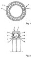
- FIG. 1 indicated that at least the inner roller bearing ring 2 of the rolling bearing 1 consists of a solid composite of two layers of different metallic materials, wherein the region of the raceway 6 for the rolling elements 4 of a steel with very high hardness and wear resistance and the core portion 7 of the rolling bearing ring 2 from a steel with high toughness is formed.
- a material for the raceway 6 of the rolling elements 4 is a powder metallurgy high-speed steel with a high content of carbide-forming Alloy elements and a high carbon content provided, while the material for the core portion 7 of the rolling bearing ring 2 made of a hot-work steel with a low content compared to the raceway material 11 carbide-forming alloying elements and low carbon content.
- both materials are bonded to one another by diffusion bonding, the material for the raceway 6 of the rolling elements 4 being formed by the high-speed steel S 10-2-5-8 PM, which contains more than 5% of the alloying components Cr, Mo, W and V and more as 0.8% carbon content, while the material for the core portion 7 of the rolling bearing ring 2 is formed by the hot work tool X40CrMoV5-1 having less than 12% alloy components Cr, Mo, W and V and less than 0.5% carbon content.
- FIG. 3 It is apparent here that first a steel cylinder 8 made of the material of the core region 7 of the rolling bearing ring 2 is inserted into a thin-walled cylindrical steel capsule 9 and then the cavity 10 between the steel cylinder 8 and the steel capsule 9 is filled with the metal powder of the raceway material 11 and compacted manually. Thereafter, with the thus prepared steel capsule 9, the sintering of the raceway material 11 and the simultaneous material connection of the same with the steel cylinder 8 by diffusion welding by means of hot isostatic pressing.
- the steel capsule 9 is a high, in FIG.
Claims (6)
- Bague de roulement, destinée en particulier à des roulements soumis à de fortes contraintes dans des réacteurs d'avions, qui est constituée d'un composite solide de deux couches en matériaux métalliques différents, dans laquelle la région de la piste de roulement (6) pour les corps de roulement (4) se compose d'un acier présentant une dureté et une résistance à l'usure très élevées et la région de noyau (7) de la bague de roulement (2) se compose d'un acier à haute ductilité, caractérisée en ce qu'il est prévu, comme matériau destiné à la piste de roulement (6) des corps de roulement (4), un acier à coupe rapide obtenu par la métallurgie des poudres et présentant une teneur élevée en éléments d'alliage formateurs de carbures et une haute teneur en carbone, tandis que le matériau destiné à la région de noyau (7) de la bague de roulement (2) se compose d'un acier pour travail à chaud présentant, par comparaison avec le matériau (11) destiné à la piste de roulement, une faible teneur en éléments d'alliage formateurs de carbures et une faible teneur en carbone, et en ce que les deux matériaux sont assemblés l'un à l'autre en complémentarité de matière par un procédé de soudage par diffusion.
- Bague de roulement selon la revendication 1, caractérisé en ce que le matériau destiné à la piste de roulement (6) des corps de roulement (4) est formé de préférence par l'acier à coupe rapide S 10-2-5-8 PM, qui présente plus de 5 % de composants d'alliage Cr, Mo, W et V et dont la teneur en carbone est supérieure à 0,8 %.
- Bague de roulement selon la revendication 1, caractérisée en ce que le matériau destiné à la région de noyau (7) de la bague de roulement (2) est formé de préférence par l'acier pour travail à chaud X40CrMoV5-1, qui présente moins de 12 % de composants d'alliage Cr, Mo, W et V, et dont la teneur en carbone est inférieure à 0,5 %.
- Procédé pour la fabrication d'une bague de roulement présentant les caractéristiques de la revendication 1, caractérisé par les étapes suivantes:a) placement central d'un cylindre en acier (8) ou placement concentrique d'un tube d'acier constitué du matériau destiné à la région de noyau (7) de la bague de roulement (2), dans une enveloppe cylindrique en acier à paroi mince (9);b) remplissage de l'espace creux (10) entre le cylindre en acier (8) et l'enveloppe en acier (9) ou de l'espace creux du tube d'acier avec la poudre métallique du matériau (11) destiné la piste de roulement, et compression de celle-ci;c) frittage du matériau (11) destiné à la piste de roulement et liaison simultanée de celui-ci au cylindre en acier (8) ou au tube d'acier de la région de noyau (7) par soudage par diffusion au moyen d'une opération de compactage isostatique à chaud;d) usinage de l'alésage central (12) dans le matériau destiné à la région de noyau (7) ou dans le matériau destiné à la piste de roulement et coupe de l'ébauche composite en bagues composites individuelles (13);e) usinage d'un canal de roulement (16) dans le matériau (11) destiné à la piste de roulement avec enfoncement simultané de l'épaisseur de couche de celui-ci par laminage de la bague composite (13) entre deux cylindres de profilage (14, 15);f) réalisation du contour extérieur approximatif de la bague de roulement (2) par usinage de la bague composite (13) suivie de durcissement et de meulage aux dimensions définitives de la bague de roulement.
- Procédé pour la fabrication d'une bague de roulement selon la revendication 4, caractérisé en ce que le frittage et le soudage par diffusion simultané des deux matériaux destinés à la piste de roulement (6) et à la région de noyau (7) de la bague de roulement (2) par compactage isostatique à chaud sont effectués de préférence sous une pression d'environ 1000 bars et à une température de 1000°C à 1200°C.
- Procédé pour la fabrication d'une bague de roulement selon la revendication 4, caractérisé en ce que le durcissement final de la bague de roulement (2) est effectué de préférence à une température comprise entre 1000°C et 1200°C, de telle manière que le matériau (11) destiné à la piste de roulement présente une dureté d'au moins 750 HV et le matériau destiné à la région de noyau (7) une dureté d'au moins 500 HV.
Applications Claiming Priority (2)
| Application Number | Priority Date | Filing Date | Title |
|---|---|---|---|
| DE102005022730A DE102005022730A1 (de) | 2005-05-18 | 2005-05-18 | Wälzlagerring,insbesondere für hochbeanspruchte Wälzlager in Flugzeugtriebwerken, sowie Verfahren zu dessen Herstellung |
| PCT/DE2006/000784 WO2006122518A2 (fr) | 2005-05-18 | 2006-05-06 | Anneau de roulement destine en particulier a des roulements soumis a de fortes contraintes dans des reacteurs d'avions, et procede de realisation |
Publications (2)
| Publication Number | Publication Date |
|---|---|
| EP1882109A2 EP1882109A2 (fr) | 2008-01-30 |
| EP1882109B1 true EP1882109B1 (fr) | 2009-04-15 |
Family
ID=37037013
Family Applications (1)
| Application Number | Title | Priority Date | Filing Date |
|---|---|---|---|
| EP06722842A Expired - Fee Related EP1882109B1 (fr) | 2005-05-18 | 2006-05-06 | Anneau de roulement destine en particulier a des roulements soumis a de fortes contraintes dans des reacteurs d'avions, et procede de realisation |
Country Status (6)
| Country | Link |
|---|---|
| US (1) | US7857518B2 (fr) |
| EP (1) | EP1882109B1 (fr) |
| JP (1) | JP2008540982A (fr) |
| CA (1) | CA2615882C (fr) |
| DE (2) | DE102005022730A1 (fr) |
| WO (1) | WO2006122518A2 (fr) |
Cited By (1)
| Publication number | Priority date | Publication date | Assignee | Title |
|---|---|---|---|---|
| US9555501B2 (en) | 2013-04-09 | 2017-01-31 | Aktiebolaget Skf | Process for obtaining a mechanical component |
Families Citing this family (14)
| Publication number | Priority date | Publication date | Assignee | Title |
|---|---|---|---|---|
| JP5429730B2 (ja) * | 2007-11-30 | 2014-02-26 | Ntn株式会社 | 機械部品の製造方法および機械部品 |
| WO2010064145A2 (fr) * | 2008-12-04 | 2010-06-10 | Corts, Jochen | Paliers en acier composite |
| JP5310338B2 (ja) * | 2009-07-15 | 2013-10-09 | 株式会社ジェイテクト | 転がり軸受の取付構造 |
| DE102010014960A1 (de) | 2010-04-14 | 2011-10-20 | Schaeffler Technologies Gmbh & Co. Kg | Wälzkörper insbesondere in Werkzeugmaschinenspindeln und Verfahren zu dessen Herstellung |
| DE102010019587B4 (de) | 2010-05-05 | 2022-02-03 | Schaeffler Technologies AG & Co. KG | Wälzlager |
| WO2013088201A1 (fr) * | 2011-12-14 | 2013-06-20 | AMSC Austria GmbH | Palier, convertisseur d'énergie éolienne et procédé de fabrication d'un palier |
| FR3000149B1 (fr) * | 2012-12-21 | 2015-01-16 | Skf Aerospace France | Procede de fabrication d'un roulement a billes, notamment pour une vanne papillon en environnement aeronautique |
| DE102013100580A1 (de) * | 2013-01-21 | 2014-07-24 | Deutsche Edelstahlwerke Gmbh | Verfahren zum Herstellen eines als metallischer Verbundwerkstoff ausgeführten Flachprodukts, Stahlflachprodukt und Verwendung eines Stahlflachprodukts |
| SE537381C2 (sv) * | 2013-04-09 | 2015-04-14 | Skf Ab | Lagerkomponentsdel, lagerkomponent och process för tillverkning av en lagerkomponent |
| DE112014001875T5 (de) * | 2013-04-09 | 2015-12-24 | Aktiebolaget Skf | Lagerteil und sein Herstellungsverfahren |
| SE536978C2 (sv) * | 2013-04-12 | 2014-11-18 | Skf Ab | Lagerkomponentdel och en metod att forma en lagerkomponent |
| DE102016114895A1 (de) * | 2016-08-11 | 2018-02-15 | Thyssenkrupp Ag | Verfahren zum Härten einer Wälzkörperlaufbahn eines Wälzlagerrings und Wälzlagerring |
| CN106763213B (zh) * | 2017-01-04 | 2018-10-09 | 宁波银球小型轴承有限公司 | 一种高润滑式洗衣机高速电机轴承 |
| DE102019218794A1 (de) * | 2019-12-03 | 2021-06-10 | Thyssenkrupp Ag | Verfahren zur Erhöhung der Tragfähigkeit und Walzvorrichtung zum Hartwalzen einer randschichtgehärteten Wälzlagerlaufbahn |
Family Cites Families (21)
| Publication number | Priority date | Publication date | Assignee | Title |
|---|---|---|---|---|
| DE200923C (fr) * | 1906-08-03 | |||
| US2845311A (en) * | 1954-04-26 | 1958-07-29 | Gen Motors Corp | Antifriction bearing |
| US3409966A (en) * | 1966-04-22 | 1968-11-12 | Bethlehem Steel Corp | Method of producing bi-metal bearing sleeve |
| FR1561481A (fr) * | 1968-02-16 | 1969-03-28 | ||
| US3665585A (en) * | 1970-12-04 | 1972-05-30 | Federal Mogul Corp | Composite heavy-duty mechanism element and method of making the same |
| US3791706A (en) * | 1971-06-09 | 1974-02-12 | Formmet Corp | Forged ring structure of multiple cast metals |
| US3770332A (en) * | 1971-06-14 | 1973-11-06 | Federal Mogul Corp | Composite heavy-duty bushing and method of making the same |
| US3762881A (en) * | 1971-06-14 | 1973-10-02 | Federal Mogul Corp | Composite high strength machine element and method of making the same |
| US3772935A (en) * | 1972-03-20 | 1973-11-20 | W Dunn | Composite heavy-duty sintered powdered machine element |
| FR2372348A1 (fr) * | 1976-10-26 | 1978-06-23 | Roulements Soc Nouvelle | Bague composite pour roulement et son procede de fabrication |
| FR2436642A1 (fr) * | 1978-09-25 | 1980-04-18 | Roulements Soc Nouvelle | Procede de fabrication d'une bague de roulement composite |
| JPS56163821A (en) | 1980-05-19 | 1981-12-16 | Ntn Toyo Bearing Co Ltd | Manufacture of annular material |
| JPS58137621A (ja) * | 1982-02-10 | 1983-08-16 | Fuji Seikou Kk | 軸受 |
| JPS58163821A (ja) * | 1982-03-19 | 1983-09-28 | Fuji Seikou Kk | 軸受 |
| JPS58178804A (ja) * | 1982-04-14 | 1983-10-19 | Hitachi Ltd | 蒸気タ−ビンロ−タシヤフト |
| DE3919199A1 (de) * | 1989-06-13 | 1990-12-20 | Skf Gmbh | Verfahren zur herstellung von waelzlagerelementen |
| JPH0469406A (ja) * | 1990-07-05 | 1992-03-04 | Ube Ind Ltd | ボールベアリング |
| JPH06341443A (ja) * | 1993-06-03 | 1994-12-13 | Nippon Thompson Co Ltd | 非磁性軌道体及びその製造方法 |
| ES2181827T3 (es) * | 1996-06-17 | 2003-03-01 | Hau Hanspeter | Acero polvometalurgico resistente al calor y procedimiento para su fabricacion. |
| US20030019106A1 (en) * | 2001-04-22 | 2003-01-30 | Diamicron, Inc. | Methods for making bearings, races and components thereof having diamond and other superhard surfaces |
| DE10343782A1 (de) * | 2003-09-22 | 2005-04-14 | Mtu Aero Engines Gmbh | Verfahren zur Herstellung von Bauteilen |
-
2005
- 2005-05-18 DE DE102005022730A patent/DE102005022730A1/de not_active Withdrawn
-
2006
- 2006-05-06 EP EP06722842A patent/EP1882109B1/fr not_active Expired - Fee Related
- 2006-05-06 CA CA2615882A patent/CA2615882C/fr not_active Expired - Fee Related
- 2006-05-06 JP JP2008515037A patent/JP2008540982A/ja active Pending
- 2006-05-06 DE DE502006003454T patent/DE502006003454D1/de active Active
- 2006-05-06 US US11/914,616 patent/US7857518B2/en not_active Expired - Fee Related
- 2006-05-06 WO PCT/DE2006/000784 patent/WO2006122518A2/fr active Application Filing
Cited By (1)
| Publication number | Priority date | Publication date | Assignee | Title |
|---|---|---|---|---|
| US9555501B2 (en) | 2013-04-09 | 2017-01-31 | Aktiebolaget Skf | Process for obtaining a mechanical component |
Also Published As
| Publication number | Publication date |
|---|---|
| EP1882109A2 (fr) | 2008-01-30 |
| DE102005022730A1 (de) | 2006-11-23 |
| WO2006122518A2 (fr) | 2006-11-23 |
| JP2008540982A (ja) | 2008-11-20 |
| DE502006003454D1 (de) | 2009-05-28 |
| CA2615882A1 (fr) | 2006-11-23 |
| CA2615882C (fr) | 2014-02-25 |
| US7857518B2 (en) | 2010-12-28 |
| WO2006122518A3 (fr) | 2007-01-04 |
| US20080212911A1 (en) | 2008-09-04 |
Similar Documents
| Publication | Publication Date | Title |
|---|---|---|
| EP1882109B1 (fr) | Anneau de roulement destine en particulier a des roulements soumis a de fortes contraintes dans des reacteurs d'avions, et procede de realisation | |
| DE19630115C2 (de) | Verfahren zum Herstellen eines Kegelrades sowie kombinierte Pressenvorrichtung | |
| WO2001081643A1 (fr) | Composant de roulement | |
| DD151126A5 (de) | Verfahren und vorrichtung zur herstellung von nockenwellen | |
| DE2310536A1 (de) | Verfahren zur herstellung von gegenstaenden aus verbundmetall | |
| DE2352578B2 (de) | Wälzlagerring aus Sintermetall und Verfahren zu dessen Herstellung | |
| DE102005019482A1 (de) | Kegelrollenlager | |
| DE112013001748T5 (de) | Gesintertes Bauteil, Zahnrad für Anlasser, und Produktionsverfahren davon | |
| EP3428300A1 (fr) | Rouleau pour un dispositif moulin et / ou presse, en particulier un rouleau de pressage pour une presse de fabrication de pellets et procédé de fabrication de rouleau | |
| EP3228889B1 (fr) | Élément de chemin de roulement pour un roulement de grande dimension et ensemble de palier | |
| EP2725208B1 (fr) | Came multiple | |
| DE112007003622B4 (de) | Verfahren zum Erhalten eines Zahnrads mit variierender Einsatzhärtetiefe | |
| EP2024654A2 (fr) | Composant de palier à roulement et procédé de fabrication dudit composant | |
| EP1778991B1 (fr) | Palier a roulements comprenant au moins un element realise par emboutissage de precision et dote d'une surface de roulement ou de guidage pour elements de roulement, procede pour fabriquer un element de ce type | |
| DE102016103752A1 (de) | Verfahren zur Herstellung eines Messing oder Bronze aufweisenden Verbundbauteils mittels Sinterpassung | |
| EP2364800A1 (fr) | Corps composite pressé de manière isostatique à chaud, procédé de fabrication et d'utilisation | |
| DE112014001906B4 (de) | Lagerteil und Verfahren zur Herstellung eines Lagerteils | |
| EP1681365B1 (fr) | Procédé de fabrication des composants fortement chargés | |
| AT512939A4 (de) | Verfahren zur Herstellung einer Verbundwalze und damit hergestellte Verbundwalze | |
| DE112005002568T5 (de) | Sinterlegierungen für Nockenbuckel und andere Gegenstände mit hohem Verschleiß | |
| DE4307560A1 (de) | Verfahren zur pulvermetallurgischen Herstellung eines bereichsweise unterschiedlichen Belastungsarten ausgesetzten Maschinenteils | |
| DE102012203110A1 (de) | Verfahren zur Herstellung eines Lagerbauteils | |
| EP1753887B1 (fr) | Composant moteur soumis a des contraintes elevees | |
| DE102023204134A1 (de) | Hochpräzisionswälzlager für hochgeschwindigkeitsanwendungen und hohe anpressdrücke sowie ein entsprechendes verfahren | |
| WO2009143829A2 (fr) | Procédé de fabrication d'un palier à roulement résistant à la corrosion |
Legal Events
| Date | Code | Title | Description |
|---|---|---|---|
| PUAI | Public reference made under article 153(3) epc to a published international application that has entered the european phase |
Free format text: ORIGINAL CODE: 0009012 |
|
| 17P | Request for examination filed |
Effective date: 20071031 |
|
| AK | Designated contracting states |
Kind code of ref document: A2 Designated state(s): DE FR GB IT SE |
|
| RBV | Designated contracting states (corrected) |
Designated state(s): DE FR GB IT SE |
|
| DAX | Request for extension of the european patent (deleted) | ||
| GRAP | Despatch of communication of intention to grant a patent |
Free format text: ORIGINAL CODE: EPIDOSNIGR1 |
|
| GRAP | Despatch of communication of intention to grant a patent |
Free format text: ORIGINAL CODE: EPIDOSNIGR1 |
|
| GRAS | Grant fee paid |
Free format text: ORIGINAL CODE: EPIDOSNIGR3 |
|
| GRAA | (expected) grant |
Free format text: ORIGINAL CODE: 0009210 |
|
| AK | Designated contracting states |
Kind code of ref document: B1 Designated state(s): DE FR GB IT SE |
|
| REG | Reference to a national code |
Ref country code: GB Ref legal event code: FG4D Free format text: NOT ENGLISH |
|
| REF | Corresponds to: |
Ref document number: 502006003454 Country of ref document: DE Date of ref document: 20090528 Kind code of ref document: P |
|
| REG | Reference to a national code |
Ref country code: SE Ref legal event code: TRGR |
|
| PLBE | No opposition filed within time limit |
Free format text: ORIGINAL CODE: 0009261 |
|
| STAA | Information on the status of an ep patent application or granted ep patent |
Free format text: STATUS: NO OPPOSITION FILED WITHIN TIME LIMIT |
|
| 26N | No opposition filed |
Effective date: 20100118 |
|
| REG | Reference to a national code |
Ref country code: GB Ref legal event code: 732E Free format text: REGISTERED BETWEEN 20110407 AND 20110413 |
|
| REG | Reference to a national code |
Ref country code: FR Ref legal event code: PLFP Year of fee payment: 11 |
|
| REG | Reference to a national code |
Ref country code: FR Ref legal event code: PLFP Year of fee payment: 12 |
|
| PGFP | Annual fee paid to national office [announced via postgrant information from national office to epo] |
Ref country code: DE Payment date: 20170731 Year of fee payment: 12 |
|
| REG | Reference to a national code |
Ref country code: FR Ref legal event code: PLFP Year of fee payment: 13 |
|
| PGFP | Annual fee paid to national office [announced via postgrant information from national office to epo] |
Ref country code: IT Payment date: 20180524 Year of fee payment: 13 Ref country code: FR Payment date: 20180525 Year of fee payment: 13 |
|
| PGFP | Annual fee paid to national office [announced via postgrant information from national office to epo] |
Ref country code: SE Payment date: 20180524 Year of fee payment: 13 |
|
| PGFP | Annual fee paid to national office [announced via postgrant information from national office to epo] |
Ref country code: GB Payment date: 20180530 Year of fee payment: 13 |
|
| REG | Reference to a national code |
Ref country code: DE Ref legal event code: R119 Ref document number: 502006003454 Country of ref document: DE |
|
| PG25 | Lapsed in a contracting state [announced via postgrant information from national office to epo] |
Ref country code: DE Free format text: LAPSE BECAUSE OF NON-PAYMENT OF DUE FEES Effective date: 20181201 |
|
| REG | Reference to a national code |
Ref country code: DE Ref legal event code: R081 Ref document number: 502006003454 Country of ref document: DE Owner name: SCHAEFFLER TECHNOLOGIES AG & CO. KG, DE Free format text: FORMER OWNER: SCHAEFFLER KG, 97421 SCHWEINFURT, DE |
|
| GBPC | Gb: european patent ceased through non-payment of renewal fee |
Effective date: 20190506 |
|
| PG25 | Lapsed in a contracting state [announced via postgrant information from national office to epo] |
Ref country code: SE Free format text: LAPSE BECAUSE OF NON-PAYMENT OF DUE FEES Effective date: 20190507 |
|
| PG25 | Lapsed in a contracting state [announced via postgrant information from national office to epo] |
Ref country code: GB Free format text: LAPSE BECAUSE OF NON-PAYMENT OF DUE FEES Effective date: 20190506 Ref country code: IT Free format text: LAPSE BECAUSE OF NON-PAYMENT OF DUE FEES Effective date: 20190506 |
|
| REG | Reference to a national code |
Ref country code: SE Ref legal event code: EUG |
|
| PG25 | Lapsed in a contracting state [announced via postgrant information from national office to epo] |
Ref country code: FR Free format text: LAPSE BECAUSE OF NON-PAYMENT OF DUE FEES Effective date: 20190531 |
|
| P01 | Opt-out of the competence of the unified patent court (upc) registered |
Effective date: 20230523 |