EP1881911B1 - Getriebestufe eines stellantriebs - Google Patents
Getriebestufe eines stellantriebs Download PDFInfo
- Publication number
- EP1881911B1 EP1881911B1 EP06829473A EP06829473A EP1881911B1 EP 1881911 B1 EP1881911 B1 EP 1881911B1 EP 06829473 A EP06829473 A EP 06829473A EP 06829473 A EP06829473 A EP 06829473A EP 1881911 B1 EP1881911 B1 EP 1881911B1
- Authority
- EP
- European Patent Office
- Prior art keywords
- bearing
- gear stage
- stage according
- axis
- oscillatory body
- Prior art date
- Legal status (The legal status is an assumption and is not a legal conclusion. Google has not performed a legal analysis and makes no representation as to the accuracy of the status listed.)
- Not-in-force
Links
Images


Classifications
-
- B—PERFORMING OPERATIONS; TRANSPORTING
- B60—VEHICLES IN GENERAL
- B60N—SEATS SPECIALLY ADAPTED FOR VEHICLES; VEHICLE PASSENGER ACCOMMODATION NOT OTHERWISE PROVIDED FOR
- B60N2/00—Seats specially adapted for vehicles; Arrangement or mounting of seats in vehicles
- B60N2/02—Seats specially adapted for vehicles; Arrangement or mounting of seats in vehicles the seat or part thereof being movable, e.g. adjustable
- B60N2/22—Seats specially adapted for vehicles; Arrangement or mounting of seats in vehicles the seat or part thereof being movable, e.g. adjustable the back-rest being adjustable
- B60N2/225—Seats specially adapted for vehicles; Arrangement or mounting of seats in vehicles the seat or part thereof being movable, e.g. adjustable the back-rest being adjustable by cycloidal or planetary mechanisms
- B60N2/2252—Seats specially adapted for vehicles; Arrangement or mounting of seats in vehicles the seat or part thereof being movable, e.g. adjustable the back-rest being adjustable by cycloidal or planetary mechanisms in which the central axis of the gearing lies inside the periphery of an orbital gear, e.g. one gear without sun gear
-
- B—PERFORMING OPERATIONS; TRANSPORTING
- B60—VEHICLES IN GENERAL
- B60N—SEATS SPECIALLY ADAPTED FOR VEHICLES; VEHICLE PASSENGER ACCOMMODATION NOT OTHERWISE PROVIDED FOR
- B60N2/00—Seats specially adapted for vehicles; Arrangement or mounting of seats in vehicles
- B60N2/02—Seats specially adapted for vehicles; Arrangement or mounting of seats in vehicles the seat or part thereof being movable, e.g. adjustable
- B60N2/0224—Non-manual adjustments, e.g. with electrical operation
- B60N2/02246—Electric motors therefor
-
- B—PERFORMING OPERATIONS; TRANSPORTING
- B60—VEHICLES IN GENERAL
- B60N—SEATS SPECIALLY ADAPTED FOR VEHICLES; VEHICLE PASSENGER ACCOMMODATION NOT OTHERWISE PROVIDED FOR
- B60N2/00—Seats specially adapted for vehicles; Arrangement or mounting of seats in vehicles
- B60N2/90—Details or parts not otherwise provided for
- B60N2/919—Positioning and locking mechanisms
- B60N2/933—Positioning and locking mechanisms rotatable
-
- F—MECHANICAL ENGINEERING; LIGHTING; HEATING; WEAPONS; BLASTING
- F16—ENGINEERING ELEMENTS AND UNITS; GENERAL MEASURES FOR PRODUCING AND MAINTAINING EFFECTIVE FUNCTIONING OF MACHINES OR INSTALLATIONS; THERMAL INSULATION IN GENERAL
- F16H—GEARING
- F16H1/00—Toothed gearings for conveying rotary motion
- F16H1/28—Toothed gearings for conveying rotary motion with gears having orbital motion
- F16H1/32—Toothed gearings for conveying rotary motion with gears having orbital motion in which the central axis of the gearing lies inside the periphery of an orbital gear
- F16H1/321—Toothed gearings for conveying rotary motion with gears having orbital motion in which the central axis of the gearing lies inside the periphery of an orbital gear the orbital gear being nutating
-
- H—ELECTRICITY
- H02—GENERATION; CONVERSION OR DISTRIBUTION OF ELECTRIC POWER
- H02K—DYNAMO-ELECTRIC MACHINES
- H02K41/00—Propulsion systems in which a rigid body is moved along a path due to dynamo-electric interaction between the body and a magnetic field travelling along the path
- H02K41/06—Rolling motors, i.e. motors having the rotor axis parallel to the stator axis and following a circular path as the rotor rolls around the inside or outside of the stator ; Nutating motors, i.e. having the rotor axis parallel to the stator axis inclined with respect to the stator axis and performing a nutational movement as the rotor rolls on the stator
- H02K41/065—Nutating motors
-
- Y—GENERAL TAGGING OF NEW TECHNOLOGICAL DEVELOPMENTS; GENERAL TAGGING OF CROSS-SECTIONAL TECHNOLOGIES SPANNING OVER SEVERAL SECTIONS OF THE IPC; TECHNICAL SUBJECTS COVERED BY FORMER USPC CROSS-REFERENCE ART COLLECTIONS [XRACs] AND DIGESTS
- Y10—TECHNICAL SUBJECTS COVERED BY FORMER USPC
- Y10T—TECHNICAL SUBJECTS COVERED BY FORMER US CLASSIFICATION
- Y10T74/00—Machine element or mechanism
- Y10T74/19—Gearing
- Y10T74/19023—Plural power paths to and/or from gearing
- Y10T74/19042—Friction-type gearing
Definitions
- the invention relates to a gear stage of an actuator with the features of the preamble of claim 1.
- a gear stage of this kind is in the WO 96/05451 A1 disclosed. Similar gear stages show the WO 00/39483 A1 and the WO 9617187 A1 .
- a gear stage which is realized in a fitting with two toothed, meshing joint parts.
- One of the two joint parts forms a fixed bearing, while the other joint part serves as a tumbling body, rests in a single point of contact on the first-mentioned joint part and in the drive case performs a rolling movement, which is a rotational movement about a parallel to the axis of the bearing and this orbiting axis.
- the invention is based on the object to provide an alternative transmission stage of the type mentioned. This object is achieved by a gear stage with the features of claim 1.
- Advantageous embodiments are the subject of the dependent claims.
- the wobble body By the axis of the wobble body is inclined at an angle relative to the axis of the bearing, a different ratio between the loaded in the radial direction and in the axial direction of space can be adjusted.
- the wobble body abuts the bearing in two contact points.
- rotation by 180 ° and axially staggered arrangement significantly fewer components needed.
- the two axes intersect in one point. Further simplifications of the geometric relationships are achieved, for example, in that the wobble body and the bearing-both at least in sections-are cylindrically symmetrical with different diameters. Swash bodies and bearings can interact as a friction gear or by means of a toothing.
- the output is concentric with the axis of the bearing.
- the wobble body on a tapered receptacle for the output wherein as the output preferably a recording contacting shaft is provided.
- the opening angle of the receptacle is selected according to the inclination of the wobble body, so that the output can rotate about the axis of the bearing.
- a provided at the narrowest point of the recording contact circle with a center is then constantly in contact with the output.
- This center point which is preferably at the same time the intersection of the axes of the wobble body and the bearing, may for example be arranged in the middle between the points of contact, which facilitates the formation of symmetrical force relationships.
- the drive of the wobble body can be done for example by means of a Wälzexzenters, which is generated by a rotating Wälzexzenterkugel.
- the spherical shape again allows a compensation of the inclination of the wobble body, whereby a concentric to the axis of the bearing drive is possible.
- a motor of the actuator with the gear stage is so tightly integrated, that the wobble body already carries rotor magnets of the motor, while at the bearing or on a bearing housing a cooperating with the rotor magnet stator is arranged, preferably electronically is commuted.
- the compensation of the effects of the inclination of the wobble body then takes place for example by the locally different, in particular axially different commutation of the stator.
- the actuator provided with the transmission stage according to the invention is preferred in a vehicle seat - with a load-absorbing gear of a fitting combined - used as a backrest tilt adjuster, but could also be used elsewhere in a vehicle seat.
- a gear stage 1 of an actuator 3 in a vehicle seat 4 of a motor vehicle has a fixed (ie connected to the structure of the vehicle seat 4) housing 8 and a wobble body 11, which is at least partially enclosed by the housing 8 and rotatably supported within the same in a bearing 12 is.
- the operating principle of gear stage 1 is off Fig. 1 seen.
- the wobble body 11 is - at least in sections - cylindrically symmetric, the (outer) Diameter d 11 of this cylinder is smaller than the (inner) diameter d 12 of the present case also cylindrically symmetric bearing 12.
- the symmetries of the wobble body 11 and the bearing 12 each define an axis A 11 and A 12th
- the axis A 11 of the wobble body 11 is inclined at a non-zero angle ⁇ relative to the axis A 12 of the bearing 12, that is obliquely thereto.
- the wobble body 11 is driven at a projecting beyond the bearing 12 end by a driving force which acts on the outside of the wobble body 11, whereby the oppositely directed normal or radial forces in the contact points B 1 , B 2 are generated, and a circumferential Direction, whereby the contact points B 1 , B 2 rotate and thus the tumbling body 11 rotates, more precisely, rolls on the bearing 12.
- the axis A 11 of the wobble body 11 thereby moves on a conical surface about the axis A 12 of the bearing 12.
- the tumbling body 11 performs a rolling movement with superimposed wobbling motion, that is, with one rotating eccentricity (d 12 - d 11 / cos ⁇ ) / 2, ie at a small inclination angle ⁇ approximately (d 12 - d 11 ) / 2.
- This eccentricity is small compared to the diameters d 11 and d 12 , preferably at most in the range of less percent ie usually less than 0.5 mm.
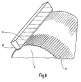
- the material pairings are suitably selected, optionally provided surface coatings and / or realized suitable contact geometries, such as rings in V-shaped Ring grooves or a gearing, as described in detail later Fig. 8 is shown.
- the radial forces in the contact points B 1 , B 2 also increase when the attack area of the driving force in a relation to the length a of the bearing 12 large distance b to the bearing 12 takes place.
- the wobble body 11 is provided with a double-conical inner bore, hereinafter referred to as a receptacle 15, whose opening angle is 2 ⁇ .
- the receptacle has at its narrowest point a cross section in the form of a contact circle 17 with a center M and a diameter d 17 .
- the center M is also the intersection of the axes A 11 , A 12 .
- the wobble body 11 is in Fig. 1 arranged so that the center M comes to lie in the middle between the points of contact B 1 , B 2 , ie along the axis A 12 of the bearing 12 at a / 2, which has the advantage of storage in the center of gravity and thus reducing mass forces.
- a shaft with the contact circle 17 is introduced as a cross section in the tumbling body 11, which then bears against the wall of the receptacle 15 touching and is entrained upon rotation of the tumbling body 11. Since the opening angle of the receptacle 15 compensates for the inclination of the axis A 11 of the wobble body 11 and since the local eccentricity in the center M is zero (and in the plane of the contact circle 17 is very small), the shaft about the axis A 12 of the bearing Turn 12 without wobbling deviations from a rotational movement are noticeable. The ratio between the (small) speed of this shaft and the (large) speed of the driving force is approximately d 12 (d 12 - d 11 ). To improve the contact between the wobble body 11 and the shaft, a special contact geometry, for example a curved tooth profile, may be provided on the contact circle 17.
- a special contact geometry for example a curved tooth profile
- Fig. 5 Exemplary is in Fig. 5 illustrated how the driving force for the transmission stage 1 according to the invention by means of a suitable drive 21 is initiated.
- the bearing 12 is opposite Fig. 1 added to obliquely walled end portions, ie truncated cones on which the wobble body 11 bears touching.
- the wobble body 11 is axially extended at one end with a cylindrical portion of lesser diameter, on which the wobble body 11 an inner bearing ring 23 to the half Bearing a single Wälzexzenterkugel 25 carries, which is also half in an outer bearing ring 27 mounted on the drive 21.
- the drive 21 in turn is mounted in the housing 8, for example by means of a ball bearing.
- the Wälzexzenterkugel 25 forms a Wälzexzenter and braced the wobble body 11 and the drive 21 to each other so that rotation of the drive 21 by means of revolving rolling the Wälzexzenterkugel 25 causes the desired rolling movement of the wobble body 11 on the bearing 12.
- FIG. 6 An actuator 3, in which the transmission stage 1 according to the invention and a motor 31 are integrated, is in Fig. 6 shown, wherein the previously described components of the gear stage 1 including the system of the wobble body 11 are shown only schematically on the bearing 12.
- the wobble body 11 at one end in the circumferential direction uniformly distributed more rotor magnets 33, so represents the rotor, while the housing 8 - in the vicinity of the rotor magnets 33 - a stator 34 is arranged.
- the circumferential radial forces in the contact points B 1 , B 2 and thus the overturning moment for the tumbling body 11 are generated by the motor 31 electromagnetically.
- the cooperating with the rotor magnet 33 stator 34 is commutated electronically in the present case.
- the wobble body 11 now encloses the bearing 12, ie d 11 > d 12 , and is in a hollow cylindrical portion in the contact points B 1 , B 2 touching on the disk-shaped bearing 12 at.
- the wobble body 11 also has aschreibkegelige material invagination, the inside of which forms the receptacle 15 including the contact circle 17, which cooperates with the serving as an output shaft.
- the inner bearing of the wobble body 11 makes it possible to distribute the rotor magnets 33 over the outside of the wobble body 11, whereby the wobble body 11 builds smaller and ultimately the entire actuator 3 axially shorter.
- both in the embodiment and in the modification of the wobble body 11 and the bearing 12 act in the contact points B 1 and B 2 in the simplest case as Reibradgetriebe together, ie with a touching investment smooth surfaces.
- suitable contact geometries are also possible, preferably a toothing between wobble body 11 and bearing 12 Fig. 8 shown, the wobble body 11 has an outer toothing 41 and the - only shown in a small angular range - bearing 12 an internal toothing 42, which mesh with each other.
- Fig. 7 would be in reverse conditions.
- the difference of the rolling circles of external teeth 41 and internal teeth 42 is taken into account. This also results in a minimum eccentricity to ensure sufficient meshing.
- the ratio of the diameter of the rolling circles of external teeth 41 and internal teeth 42 must correspond to the ratio of the integer numbers of teeth of external teeth 41 and internal teeth 42.
- the gear ratio is the ratio of the number of teeth of the external teeth 41 to the difference of the numbers of teeth of internal teeth 42 and external teeth 41, so particularly large when the difference in the number of teeth is one.
- the internal toothing 42 is formed uniformly over the entire length a of the bearing 12, for example, in particular with a constant tooth height.
- the tooth heights are then adapted to the angle of inclination ⁇ .
- the geometric generation of the external teeth 41 is effected by kinematic rolling of the rolling circles of external teeth 41 and internal teeth 42. This movement generates an enveloping body, which serves as a trigger body for the external teeth 41.
- the internal teeth 42 serves as a kind of tool for producing the external teeth 41.
- the diameter of the root circle of the external teeth 41 in both directions of the axis A 11 is getting smaller (and the tip circle larger), ie the tooth height as a difference of head circle and root circle grows.
- the two portions of the external teeth 41 are not formed mirror-symmetrically to each other, but because of the preferred difference of the numbers of teeth of internal teeth 42 and external teeth 41 of one by half a tooth width in the circumferential direction of the axis A 11 offset from one another.
- the two rolling circles of the outer teeth 41 which are each outside the outer teeth 41 (ie have a larger diameter than the tip circle) are inclined relative to the rolling circles of the internal teeth 42, which is why the minimum eccentricity is lower compared to teeth with axially constant tooth heights.
- a comparatively large tooth flank is available, which is why the total radial space required is reduced.
Landscapes
- Engineering & Computer Science (AREA)
- Mechanical Engineering (AREA)
- Aviation & Aerospace Engineering (AREA)
- Transportation (AREA)
- General Engineering & Computer Science (AREA)
- Chemical & Material Sciences (AREA)
- Physics & Mathematics (AREA)
- Combustion & Propulsion (AREA)
- Electromagnetism (AREA)
- Power Engineering (AREA)
- Retarders (AREA)
- Connection Of Motors, Electrical Generators, Mechanical Devices, And The Like (AREA)
- Seats For Vehicles (AREA)
- Chairs For Special Purposes, Such As Reclining Chairs (AREA)
- Gear Transmission (AREA)
Applications Claiming Priority (2)
| Application Number | Priority Date | Filing Date | Title |
|---|---|---|---|
| DE102005061188A DE102005061188B4 (de) | 2005-12-21 | 2005-12-21 | Getriebestufe eines Stellantriebs |
| PCT/EP2006/011881 WO2007079867A1 (de) | 2005-12-21 | 2006-12-09 | Getriebestufe eines stellantriebs |
Publications (2)
| Publication Number | Publication Date |
|---|---|
| EP1881911A1 EP1881911A1 (de) | 2008-01-30 |
| EP1881911B1 true EP1881911B1 (de) | 2009-02-11 |
Family
ID=37734769
Family Applications (1)
| Application Number | Title | Priority Date | Filing Date |
|---|---|---|---|
| EP06829473A Not-in-force EP1881911B1 (de) | 2005-12-21 | 2006-12-09 | Getriebestufe eines stellantriebs |
Country Status (8)
| Country | Link |
|---|---|
| US (1) | US7631578B2 (https=) |
| EP (1) | EP1881911B1 (https=) |
| JP (1) | JP5068766B2 (https=) |
| KR (1) | KR101312658B1 (https=) |
| CN (1) | CN101331033B (https=) |
| DE (2) | DE102005061188B4 (https=) |
| RU (1) | RU2402433C2 (https=) |
| WO (1) | WO2007079867A1 (https=) |
Families Citing this family (4)
| Publication number | Priority date | Publication date | Assignee | Title |
|---|---|---|---|---|
| KR101543115B1 (ko) * | 2013-12-18 | 2015-08-07 | 현대자동차주식회사 | 자동차의 시트 햅틱 장치 |
| JP2015142454A (ja) * | 2014-01-29 | 2015-08-03 | キヤノン株式会社 | アクチュエータ及び多関節ロボットアーム |
| US11451124B2 (en) | 2018-05-23 | 2022-09-20 | Tau Motors, Inc. | Electric motor |
| KR102726818B1 (ko) * | 2020-04-13 | 2024-11-05 | 현대자동차주식회사 | 자동차용 시트의 다방향 조절 장치 |
Family Cites Families (11)
| Publication number | Priority date | Publication date | Assignee | Title |
|---|---|---|---|---|
| SU1236233A1 (ru) * | 1981-12-30 | 1986-06-07 | Завод-Втуз При Производственном Объединении "Ленинградский Металлический Завод" | Коническа планетарна передача |
| DE4436101C5 (de) * | 1993-11-30 | 2008-12-11 | Keiper Gmbh & Co.Kg | Lehneneinstellbeschlag für Sitze mit verstellbarer Rückenlehne, insbesondere Kraftfahrzeugsitze |
| SE9402701L (sv) | 1994-08-12 | 1995-09-18 | Gustav Rennerfelt | Excenterväxel |
| SE503483C2 (sv) * | 1994-11-29 | 1996-06-24 | Scandrive Hallstahammar Ab | Excenterväxel |
| RU9912U1 (ru) * | 1998-01-20 | 1999-05-16 | Евгений Иванович Филипычев | Коническая волновая передача |
| SE513311C2 (sv) * | 1998-12-29 | 2000-08-21 | Gustav Rennerfelt | Excenterväxel |
| JP3568919B2 (ja) * | 2001-07-12 | 2004-09-22 | 正明 山下 | 変速装置 |
| GB2387214B8 (en) * | 2002-04-05 | 2005-11-14 | Arvinmeritor Light Vehicle Sys | A drive transmission |
| SE524817C2 (sv) * | 2003-02-17 | 2004-10-05 | Scandrive Control Ab | Anordning för att påföra oscillerande axialrörelser på en roterbar vals |
| JP4328120B2 (ja) * | 2003-03-31 | 2009-09-09 | 住友重機械工業株式会社 | 揺動内接噛合型遊星歯車装置及びその耐久性向上方法 |
| DE102006005906A1 (de) * | 2005-08-23 | 2007-08-30 | Keiper Gmbh & Co.Kg | Getriebestufe |
-
2005
- 2005-12-21 DE DE102005061188A patent/DE102005061188B4/de not_active Expired - Fee Related
-
2006
- 2006-12-09 EP EP06829473A patent/EP1881911B1/de not_active Not-in-force
- 2006-12-09 CN CN2006800477457A patent/CN101331033B/zh not_active Expired - Fee Related
- 2006-12-09 WO PCT/EP2006/011881 patent/WO2007079867A1/de not_active Ceased
- 2006-12-09 JP JP2008546195A patent/JP5068766B2/ja not_active Expired - Fee Related
- 2006-12-09 DE DE502006002825T patent/DE502006002825D1/de active Active
- 2006-12-09 KR KR1020077029901A patent/KR101312658B1/ko not_active Expired - Fee Related
- 2006-12-09 RU RU2008129365/11A patent/RU2402433C2/ru not_active IP Right Cessation
-
2008
- 2008-06-20 US US12/214,664 patent/US7631578B2/en not_active Expired - Fee Related
Also Published As
| Publication number | Publication date |
|---|---|
| JP2009520533A (ja) | 2009-05-28 |
| KR101312658B1 (ko) | 2013-09-27 |
| CN101331033A (zh) | 2008-12-24 |
| US20090005207A1 (en) | 2009-01-01 |
| DE102005061188A1 (de) | 2007-07-05 |
| EP1881911A1 (de) | 2008-01-30 |
| CN101331033B (zh) | 2011-04-20 |
| WO2007079867A1 (de) | 2007-07-19 |
| DE102005061188B4 (de) | 2007-10-18 |
| JP5068766B2 (ja) | 2012-11-07 |
| KR20080077904A (ko) | 2008-08-26 |
| RU2402433C2 (ru) | 2010-10-27 |
| RU2008129365A (ru) | 2010-01-27 |
| US7631578B2 (en) | 2009-12-15 |
| DE502006002825D1 (de) | 2009-03-26 |
Similar Documents
| Publication | Publication Date | Title |
|---|---|---|
| DE102007061322B4 (de) | Exzentergetriebe und Verfahren zum Übertragen einer Drehkraft durch das Exzentergetriebe | |
| EP1523610B1 (de) | Vorrichtung zur veränderung der steuerzeiten einer brennkraftmaschine | |
| DE102015014087B4 (de) | Getriebe | |
| WO2002095264A1 (de) | Reibrad-umlaufgetriebe zur umformung einer drehenden in eine hin- und hergehende bewegung mit herabgesetzter frequenz | |
| WO2007134705A2 (de) | Getriebestufe für einen stellantrieb | |
| DE102004050152A1 (de) | Getriebebeschlag für einen Fahrzeugsitz | |
| DE10133230A1 (de) | Wellengetriebeeinheit | |
| DE102012210169A1 (de) | Exzentergetriebe | |
| DE102005007297A1 (de) | Fluiddynamisches Luftlagersystem zur Drehlagerung eines Motors | |
| DE102007015289A1 (de) | Oszillierendes innen eingreifendes Planetenradreduktionsgetriebe | |
| WO2005046030A1 (de) | Getriebe-antriebseinheit | |
| DE102016205748B3 (de) | Stellgetriebe | |
| WO2017092740A1 (de) | Umlaufrädergetriebe für eine kraftfahrzeugantriebseinheit | |
| EP1881911B1 (de) | Getriebestufe eines stellantriebs | |
| DE10054798A1 (de) | Elektrisch angetriebene Vorrichtung zur Drehwinkelverstellung einer Welle gegenüber ihrem Antrieb | |
| EP1917157B1 (de) | Getriebestufe | |
| WO2012152727A2 (de) | Planetengetriebeanordnung für einen sitzverstellmechanismus und verfahren zum betrieb einer solchen planetengetriebeanordnung | |
| DE29813978U1 (de) | Motorpumpeneinheit für ein Hochdruckreinigungsgerät | |
| EP2414703B1 (de) | Taumelradwolfromgetriebe | |
| DE102004049994B3 (de) | Getriebestufe für einen Fahrzeugsitz | |
| EP0866238B1 (de) | Reduktionsgetriebe | |
| DE102007009171A1 (de) | Motorischer Stellantrieb für einen Fahrzeugsitz | |
| DE202006014817U1 (de) | Motorischer Stellantrieb für einen Fahrzeugsitz | |
| DE102005039733A1 (de) | Getriebestufe | |
| DE102007038009A1 (de) | Drehzahlüberlagerungseinrichtung |
Legal Events
| Date | Code | Title | Description |
|---|---|---|---|
| PUAI | Public reference made under article 153(3) epc to a published international application that has entered the european phase |
Free format text: ORIGINAL CODE: 0009012 |
|
| 17P | Request for examination filed |
Effective date: 20071123 |
|
| AK | Designated contracting states |
Kind code of ref document: A1 Designated state(s): AT BE BG CH CY CZ DE DK EE ES FI FR GB GR HU IE IS IT LI LT LU LV MC NL PL PT RO SE SI SK TR |
|
| AX | Request for extension of the european patent |
Extension state: AL BA HR MK YU |
|
| DAX | Request for extension of the european patent (deleted) | ||
| GRAP | Despatch of communication of intention to grant a patent |
Free format text: ORIGINAL CODE: EPIDOSNIGR1 |
|
| GRAS | Grant fee paid |
Free format text: ORIGINAL CODE: EPIDOSNIGR3 |
|
| DAX | Request for extension of the european patent (deleted) | ||
| RBV | Designated contracting states (corrected) |
Designated state(s): DE FR |
|
| GRAA | (expected) grant |
Free format text: ORIGINAL CODE: 0009210 |
|
| AK | Designated contracting states |
Kind code of ref document: B1 Designated state(s): DE FR |
|
| REF | Corresponds to: |
Ref document number: 502006002825 Country of ref document: DE Date of ref document: 20090326 Kind code of ref document: P |
|
| PLBE | No opposition filed within time limit |
Free format text: ORIGINAL CODE: 0009261 |
|
| STAA | Information on the status of an ep patent application or granted ep patent |
Free format text: STATUS: NO OPPOSITION FILED WITHIN TIME LIMIT |
|
| 26N | No opposition filed |
Effective date: 20091112 |
|
| REG | Reference to a national code |
Ref country code: DE Ref legal event code: R082 Ref document number: 502006002825 Country of ref document: DE Effective date: 20140710 Representative=s name: HOSENTHIEN-HELD UND DR. HELD, DE Ref country code: DE Ref legal event code: R081 Ref document number: 502006002825 Country of ref document: DE Owner name: JOHNSON CONTROLS COMPONENTS GMBH & CO. KG, DE Free format text: FORMER OWNER: KEIPER GMBH & CO. KG, 67657 KAISERSLAUTERN, DE Effective date: 20140710 Ref country code: DE Ref legal event code: R081 Ref document number: 502006002825 Country of ref document: DE Owner name: ADIENT LUXEMBOURG HOLDING S.A.R.L., LU Free format text: FORMER OWNER: KEIPER GMBH & CO. KG, 67657 KAISERSLAUTERN, DE Effective date: 20140710 Ref country code: DE Ref legal event code: R082 Ref document number: 502006002825 Country of ref document: DE Representative=s name: LIEDHEGENER, RALF, DIPL.-ING., DE Effective date: 20140710 Ref country code: DE Ref legal event code: R081 Ref document number: 502006002825 Country of ref document: DE Owner name: ADIENT LUXEMBOURG HOLDING S.A R.L., LU Free format text: FORMER OWNER: KEIPER GMBH & CO. KG, 67657 KAISERSLAUTERN, DE Effective date: 20140710 |
|
| REG | Reference to a national code |
Ref country code: FR Ref legal event code: PLFP Year of fee payment: 10 |
|
| REG | Reference to a national code |
Ref country code: FR Ref legal event code: PLFP Year of fee payment: 11 |
|
| REG | Reference to a national code |
Ref country code: DE Ref legal event code: R082 Ref document number: 502006002825 Country of ref document: DE Representative=s name: HOSENTHIEN-HELD UND DR. HELD, DE Ref country code: DE Ref legal event code: R081 Ref document number: 502006002825 Country of ref document: DE Owner name: ADIENT LUXEMBOURG HOLDING S.A.R.L., LU Free format text: FORMER OWNER: JOHNSON CONTROLS COMPONENTS GMBH & CO. KG, 67657 KAISERSLAUTERN, DE Ref country code: DE Ref legal event code: R082 Ref document number: 502006002825 Country of ref document: DE Representative=s name: LIEDHEGENER, RALF, DIPL.-ING., DE Ref country code: DE Ref legal event code: R081 Ref document number: 502006002825 Country of ref document: DE Owner name: ADIENT LUXEMBOURG HOLDING S.A R.L., LU Free format text: FORMER OWNER: JOHNSON CONTROLS COMPONENTS GMBH & CO. KG, 67657 KAISERSLAUTERN, DE |
|
| PGFP | Annual fee paid to national office [announced via postgrant information from national office to epo] |
Ref country code: FR Payment date: 20161222 Year of fee payment: 11 |
|
| REG | Reference to a national code |
Representative=s name: LIEDHEGENER, RALF, DIPL.-ING., DE Ref country code: DE Ref legal event code: R082 Ref document number: 502006002825 Country of ref document: DE |
|
| REG | Reference to a national code |
Ref country code: DE Ref legal event code: R082 Ref document number: 502006002825 Country of ref document: DE Representative=s name: LIEDHEGENER, RALF, DIPL.-ING., DE Ref country code: DE Ref legal event code: R081 Ref document number: 502006002825 Country of ref document: DE Owner name: ADIENT LUXEMBOURG HOLDING S.A R.L., LU Free format text: FORMER OWNER: ADIENT LUXEMBOURG HOLDING S.A.R.L., LUXEMBOURG, LU |
|
| PGFP | Annual fee paid to national office [announced via postgrant information from national office to epo] |
Ref country code: DE Payment date: 20171231 Year of fee payment: 12 |
|
| REG | Reference to a national code |
Ref country code: FR Ref legal event code: ST Effective date: 20180831 |
|
| PG25 | Lapsed in a contracting state [announced via postgrant information from national office to epo] |
Ref country code: FR Free format text: LAPSE BECAUSE OF NON-PAYMENT OF DUE FEES Effective date: 20180102 |
|
| REG | Reference to a national code |
Ref country code: DE Ref legal event code: R119 Ref document number: 502006002825 Country of ref document: DE |
|
| PG25 | Lapsed in a contracting state [announced via postgrant information from national office to epo] |
Ref country code: DE Free format text: LAPSE BECAUSE OF NON-PAYMENT OF DUE FEES Effective date: 20190702 |