EP1880902A1 - Befestigungssystem einer Gepäckraumabdeckung eines Kraftfahrzeuges - Google Patents
Befestigungssystem einer Gepäckraumabdeckung eines Kraftfahrzeuges Download PDFInfo
- Publication number
- EP1880902A1 EP1880902A1 EP07381042A EP07381042A EP1880902A1 EP 1880902 A1 EP1880902 A1 EP 1880902A1 EP 07381042 A EP07381042 A EP 07381042A EP 07381042 A EP07381042 A EP 07381042A EP 1880902 A1 EP1880902 A1 EP 1880902A1
- Authority
- EP
- European Patent Office
- Prior art keywords
- tray
- coupling means
- support
- vehicle
- cylindrical
- Prior art date
- Legal status (The legal status is an assumption and is not a legal conclusion. Google has not performed a legal analysis and makes no representation as to the accuracy of the status listed.)
- Granted
Links
- 230000008878 coupling Effects 0.000 claims abstract description 28
- 238000010168 coupling process Methods 0.000 claims abstract description 28
- 238000005859 coupling reaction Methods 0.000 claims abstract description 28
- 238000009434 installation Methods 0.000 claims abstract description 12
- 238000000034 method Methods 0.000 claims abstract description 10
- 230000014759 maintenance of location Effects 0.000 claims description 10
- 238000003780 insertion Methods 0.000 claims description 4
- 230000037431 insertion Effects 0.000 claims description 4
- 239000013536 elastomeric material Substances 0.000 claims description 2
- 230000002035 prolonged effect Effects 0.000 claims description 2
- 238000004519 manufacturing process Methods 0.000 description 5
- 239000000463 material Substances 0.000 description 2
- 230000004308 accommodation Effects 0.000 description 1
- 239000007795 chemical reaction product Substances 0.000 description 1
- 230000000295 complement effect Effects 0.000 description 1
- 238000005516 engineering process Methods 0.000 description 1
- 239000000047 product Substances 0.000 description 1
- 230000000717 retained effect Effects 0.000 description 1
- 238000000926 separation method Methods 0.000 description 1
- 230000000153 supplemental effect Effects 0.000 description 1
Images
Classifications
-
- B—PERFORMING OPERATIONS; TRANSPORTING
- B60—VEHICLES IN GENERAL
- B60R—VEHICLES, VEHICLE FITTINGS, OR VEHICLE PARTS, NOT OTHERWISE PROVIDED FOR
- B60R5/00—Compartments within vehicle body primarily intended or sufficiently spacious for trunks, suit-cases, or the like
- B60R5/04—Compartments within vehicle body primarily intended or sufficiently spacious for trunks, suit-cases, or the like arranged at rear of vehicle
- B60R5/044—Compartments within vehicle body primarily intended or sufficiently spacious for trunks, suit-cases, or the like arranged at rear of vehicle luggage covering means, e.g. parcel shelves
-
- B—PERFORMING OPERATIONS; TRANSPORTING
- B60—VEHICLES IN GENERAL
- B60R—VEHICLES, VEHICLE FITTINGS, OR VEHICLE PARTS, NOT OTHERWISE PROVIDED FOR
- B60R5/00—Compartments within vehicle body primarily intended or sufficiently spacious for trunks, suit-cases, or the like
- B60R5/003—Luggage racks, e.g. for busses
-
- E—FIXED CONSTRUCTIONS
- E05—LOCKS; KEYS; WINDOW OR DOOR FITTINGS; SAFES
- E05D—HINGES OR SUSPENSION DEVICES FOR DOORS, WINDOWS OR WINGS
- E05D7/00—Hinges or pivots of special construction
- E05D7/10—Hinges or pivots of special construction to allow easy separation or connection of the parts at the hinge axis
- E05D7/1061—Hinges or pivots of special construction to allow easy separation or connection of the parts at the hinge axis in a radial direction
- E05D7/1066—Hinges or pivots of special construction to allow easy separation or connection of the parts at the hinge axis in a radial direction requiring a specific angular position
-
- B—PERFORMING OPERATIONS; TRANSPORTING
- B60—VEHICLES IN GENERAL
- B60R—VEHICLES, VEHICLE FITTINGS, OR VEHICLE PARTS, NOT OTHERWISE PROVIDED FOR
- B60R11/00—Arrangements for holding or mounting articles, not otherwise provided for
- B60R2011/0001—Arrangements for holding or mounting articles, not otherwise provided for characterised by position
- B60R2011/0003—Arrangements for holding or mounting articles, not otherwise provided for characterised by position inside the vehicle
- B60R2011/0036—Luggage compartment
-
- B—PERFORMING OPERATIONS; TRANSPORTING
- B60—VEHICLES IN GENERAL
- B60R—VEHICLES, VEHICLE FITTINGS, OR VEHICLE PARTS, NOT OTHERWISE PROVIDED FOR
- B60R11/00—Arrangements for holding or mounting articles, not otherwise provided for
- B60R2011/0042—Arrangements for holding or mounting articles, not otherwise provided for characterised by mounting means
- B60R2011/008—Adjustable or movable supports
- B60R2011/0085—Adjustable or movable supports with adjustment by rotation in their operational position
Definitions
- the present invention refers to vehicle tray coupling means, a tray that makes use of said means and a procedure for the installation of same.
- the invention has its application in motor vehicle trays located in the rear part of same which are intended to separate the inner passenger compartment from the boot area.
- each one of the lateral supports includes a surface on which the lower surface of the tray rests when it is installed in the vehicle, a coupling element that receives the anterior corner of the tray and permits its relative rotation in respect of the supports for its installation and removal in order to prevent its back and forth movement when installed.
- patent EP1452393 The disadvantage presented by patent EP1452393 is that due to the dished configuration of the front area it has to be installed in the vertical position so as to enable this front area to enter its end position. In the tray folding movement, once the front area is inserted, mechanical interference may take place with other vehicle parts, such as the rear pillars for instance, so that this type of configuration could predetermine the design of other parts of the vehicle.
- tray incorporating the pins these are located on the lateral supports.
- a tray type is known that incorporates the pins on these lateral supports located in the vehicle boot, such that by means of recesses provided in the ends located at the rear of the tray, this is engaged and permits its rotation when the vehicle hatchback is opened.
- JP57138446 Japanese patent with publication number JP57138446 "Vehicle rear tray”.
- the tray coupling means that are the object of the invention possess means of rotation that overcome the previous disadvantages by means of dispensing with the pins as an independent reference thus providing easier installation by means of a suitable geometry that does not predetermine the design of other parts located in the boot area and which does not introduce any additional part.
- the coupling also means possess suitable means for retaining the tray both in the direction of forward movement of the vehicle and in the vertical direction, the latter to prevent vibration noise being generated.
- the present invention refers to vehicle tray coupling means, a tray that makes use of said means, and a procedure for the installation of same.
- Trays are elements provided in the rear part of the vehicle in order to separate the boot area from the interior passenger compartment.
- the tray is made up of a mainly flat rigid panel, which rests at its lateral anterior ends on support elements provided on the lateral supports of the boot.
- the tray has to offer the possibility of being raised in order to obtain convenient access to the boot space. For this reason it is normally provided with cords that connect it to the rear hatchback of the vehicle, so that when this is raised, the tray is also lifted permitting access to the load area. In order to bring about this raising, the tray has joints at its anterior part.
- This joint is usually composed of pins built into the anterior ends of its sides. These pins are inserted into recesses provided in the anterior part of the lateral supports, configuring the tray joint.
- the rigid surface area of the tray is usually composed of a sandwich of materials which is produced by means of a heat-forming process.
- the pins are positioned as an insert between the layers forming the surface area of the tray.
- the swivel pins therefore require the use of additional parts, which leads to a considerable increase in the cost of the tray.
- the present invention dispenses with the pins as an additional part of the tray in order to achieve a product with a lower production cost, both by reducing the number of parts and by the application of simpler manufacturing techniques.
- the surface area of the support which essentially follows the path of rotation of the anterior end of the tray limits the possible movement of the cylindrical sector of the recess in the tray in respect of the cylindrical sector of the support swivel pin, thereby stopping the two elements from becoming disengaged during tray rotation.
- Both the cylindrical sector of the support pin and the cylindrical sector of the tray recess are co-axial, while their geometric axis also coincides with their rotation axis, which is also that of the tray assembly.
- the centre of the radius of curvature of the surface area limiting radial movement does not have to have a constant radius of curvature nor have a single centre, without it therefore not being an arc very close geometrically to a cylinder arc, producing thereby areas of varying pressure between the curvature and the anterior end of the tray, thus achieving better retention of same and spatial separation between the tray rotating means and the retaining means and, therefore, the independence of both functions.
- the procedure for installing said tray comprises at least the following steps:
- the tray that makes use of the coupling means that are the object of the invention is characterised in that its thickness is constant along its whole length.
- the fact of its being able to maintain this constancy in thickness is due to the type of material that is used.
- the use of a tray of a constant thickness means that we obtain increased accommodation in the vehicle and more space in the boot, while at the same time its weight is reduced. Furthermore, the manufacture of a constant thickness tray requires shorter production cycles and simpler jigs.
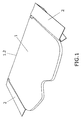
- Figure 1 is a diagrammatic perspective representation of a tray situated between the lateral supports in the horizontal position.
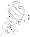
- Figure 2 is a diagrammatic perspective representation of a first specimen tray embodiment.
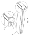
- Figure 3 is a diagrammatic perspective representation of a support intended to receive the tray of the specimen embodiment of figure 2.
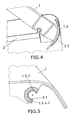
- Figure 4 is a diagrammatic lateral view of a specimen of the invention showing the layout of the tray and its corresponding support.
- Figure 5 is a diagrammatic perspective representation of a third specimen layout of the tray.
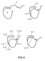
- Figure 6 is a set of diagrammatic sections representing the evolution of the installation linkage of a tray and its associated support in accordance with the specimen embodiment of the invention of figures 2 and 3.
- Figure 1 represents a tray (1) in the horizontal position and its lateral supports (2), both elements (1, 2) being coupled in the anterior area (1.2) of same (1).
- the coupling means of the tray (1) and its associated support (2) may adopt various embodiments.
- Said coupling means comprise in turn means that permit the rotation of the tray (1) and means for retaining its radial and vertical movement.
- radial refers to a movement of the cylindrical sector of the tray in respect of the cylindrical sector of the support in the direction perpendicular to the rotation axis and "vertical" to direction Z according to the orientation of the vehicle. In this way, smooth uninterrupted rotation of the tray (1) is achieved and noise and vibration in same (1) are prevented.
- the tray (1) possesses recesses (1.1), constituted in the cylindrical sectors (1.1.1), which may be greater or smaller than 180°. In the event of the cylindrical sector (1.1.1) being more than 180°, a clipping action will take place between the two elements (1, 2).
- Figures 2, 3, 4 represent cases in which the cylindrical sector (1.1.1) of the recesses (1.1) in the tray (1) is 180° or less; an embodiment is represented in figure 5 in which the cylindrical sector (1.1.1) is greater than 180°.
- said cylindrical sectors (1.1.1) encircle and are secured by clipping to the pins (2.1) of the supports (2).
- FIG 5 besides permitting rotation between tray (1) and support (2), we obtain the vertical retention of the tray (1) on the same axis.
- Figure 2 represents a tray (1) whose means for limitation of movement in the radial direction consist of a surface area (2.2) of the support (2) that essentially follows the path of rotation of the anterior end (1.2) of the tray, specifically of its final end (1.2.1).
- the tray (1) of figure 2 also has vertical retaining means that consist of the presence of at least one horizontal section (1.2.2) at the anterior end (1.2) of the tray (1) which in the operational position of same (1) is situated inferiorly and in contact with another horizontal section (2.3) located on the support (2), see figures 3 and 6.
- Figure 4 represents another embodiment of the vehicle tray coupling means.
- both the radial retention and the vertical retention are effected by way of means formed by the anterior end (1.2) of the tray (1).
- the surface area of said end (1.2) possesses a curvature coinciding essentially with the curvature of the surface (2.2) of the support (2) that limits movement in the radial direction.
- the contact between both surfaces (1.2, 2.2) in the operational position of the tray (1) establishes the retention of same (1).
- the contact between the anterior end (1.2) of the tray (1) and the surface (2.2) of the support (2) is effected at all points of both surfaces, not only at the end edge (1.2.1) of same, thereby achieving not only the radial retention of the tray (1), but also its vertical retention without any need for horizontal bearing sections (1.2.2, 2.3) to perform this function.
- Another embodiment of the coupling means - not shown - corresponds to the case in which the cylindrical sectors (1.1.1) in which the recesses (1.1) in the tray (1) are constituted are equal to 90° ⁇ 10°, the recesses (1.1) being prolonged on the posterior side with a straight section tangent to said cylindrical sector (1.1.1), so that in this way better guiding the tray (1) is obtained during its installation.
- Figure 5 represents an embodiment in which the cylindrical sectors (1.1.1) comprise arcs greater than 180°, although any of the foregoing embodiments may also be constituted with these sectors.
- said cylindrical sector (1.1.1) may be made from an elastomeric material (1.1.1.1) and therefore be deformable.
- the tray (1) that makes use of the coupling means described in the preferred embodiment possesses a thickness of 8 mm or less, thereby achieving greater lightness and reducing the possibility of vibrations and noise.
Landscapes
- Engineering & Computer Science (AREA)
- Mechanical Engineering (AREA)
- Vehicle Step Arrangements And Article Storage (AREA)
- Vehicle Cleaning, Maintenance, Repair, Refitting, And Outriggers (AREA)
Applications Claiming Priority (1)
| Application Number | Priority Date | Filing Date | Title |
|---|---|---|---|
| ES200601922A ES2315111B1 (es) | 2006-07-19 | 2006-07-19 | Medios de acoplamiento para bandeja de vehiculo, bandeja que hace uso de dichos medios y procedimiento de montaje de la misma. |
Publications (2)
| Publication Number | Publication Date |
|---|---|
| EP1880902A1 true EP1880902A1 (de) | 2008-01-23 |
| EP1880902B1 EP1880902B1 (de) | 2013-04-03 |
Family
ID=38542976
Family Applications (1)
| Application Number | Title | Priority Date | Filing Date |
|---|---|---|---|
| EP07381042A Not-in-force EP1880902B1 (de) | 2006-07-19 | 2007-05-18 | Befestigungssystem einer Gepäckraumabdeckung eines Kraftfahrzeuges |
Country Status (4)
| Country | Link |
|---|---|
| EP (1) | EP1880902B1 (de) |
| KR (1) | KR20080008225A (de) |
| CN (1) | CN101108602A (de) |
| ES (1) | ES2315111B1 (de) |
Cited By (4)
| Publication number | Priority date | Publication date | Assignee | Title |
|---|---|---|---|---|
| EP2186683A1 (de) * | 2008-11-14 | 2010-05-19 | Faurecia Automotive Industrie | Laderaumabdeckung für Kraftfahrzeug und entsprechende Eckeinheit |
| FR2951118A1 (fr) * | 2009-10-08 | 2011-04-15 | Cera | Dispositif de montage d'une plaque de recouvrement d'un compartiment a bagages de vehicule automobile |
| FR3037883A1 (fr) * | 2015-06-25 | 2016-12-30 | Cera Aps | Systeme de recouvrement d’un compartiment a bagages de vehicule automobile |
| WO2021089287A1 (de) * | 2019-11-08 | 2021-05-14 | Bayerische Motoren Werke Aktiengesellschaft | Einlegebodeneinheit |
Families Citing this family (4)
| Publication number | Priority date | Publication date | Assignee | Title |
|---|---|---|---|---|
| CN104169129B (zh) * | 2012-02-29 | 2017-08-22 | 大众汽车公司 | 中控台及其组件 |
| CN104149712A (zh) * | 2014-08-22 | 2014-11-19 | 无锡吉兴汽车声学部件科技有限公司 | 机动车辆舱室分隔机构 |
| CN107150634A (zh) * | 2017-04-14 | 2017-09-12 | 浙江零跑科技有限公司 | 一种搁物板及其安装结构 |
| CN114633696B (zh) * | 2022-03-22 | 2024-04-09 | 一汽解放汽车有限公司 | 高架箱定位结构及车辆 |
Citations (7)
| Publication number | Priority date | Publication date | Assignee | Title |
|---|---|---|---|---|
| JPS57138446A (en) | 1981-02-18 | 1982-08-26 | Nissan Motor Co Ltd | Rear baggage shelf for vehicle |
| DE3513577A1 (de) * | 1985-04-16 | 1986-10-16 | ADS-Anker GmbH, 4800 Bielefeld | Gelenkverbindung |
| DE19723838A1 (de) * | 1996-06-18 | 1998-01-02 | Volkswagen Ag | Anordnung mit einer Gepäckraumabdeckung in einem Fahrzeug |
| EP0820390A1 (de) | 1995-04-10 | 1998-01-28 | Etablissements TREVES | Befestigungsanordnung für eine hintere abdeckplatte eines fahrzeugs |
| EP1364834A2 (de) | 1999-06-11 | 2003-11-26 | Sai Automotive Sommer Industrie | Vorrichtung zum Halten und Anlenken einer abnehmbaren Kraftfahrzeugheckplatte |
| EP1452393A1 (de) | 2003-02-25 | 2004-09-01 | Mecaplast S.A.M. | Abnehmbare Hutablage für Fahrzeug und ihre Befestigungsvorrichtung |
| WO2004074044A1 (en) | 2003-02-19 | 2004-09-02 | Nissan Technical Centre Europe Ltd | Parcel shelf support |
Family Cites Families (3)
| Publication number | Priority date | Publication date | Assignee | Title |
|---|---|---|---|---|
| CH677244A5 (de) * | 1988-07-05 | 1991-04-30 | Von Roll Ag | |
| JP3718733B2 (ja) * | 1995-05-16 | 2005-11-24 | 昭和電工株式会社 | ケースにおける蓋の開閉装置 |
| FR2850917B1 (fr) * | 2003-02-12 | 2006-04-28 | Cera | Systeme de montage d'une tablette arriere de vehicule automobile |
-
2006
- 2006-07-19 ES ES200601922A patent/ES2315111B1/es active Active
-
2007
- 2007-05-18 EP EP07381042A patent/EP1880902B1/de not_active Not-in-force
- 2007-07-02 KR KR1020070066176A patent/KR20080008225A/ko not_active Ceased
- 2007-07-16 CN CNA2007101305632A patent/CN101108602A/zh active Pending
Patent Citations (8)
| Publication number | Priority date | Publication date | Assignee | Title |
|---|---|---|---|---|
| JPS57138446A (en) | 1981-02-18 | 1982-08-26 | Nissan Motor Co Ltd | Rear baggage shelf for vehicle |
| DE3513577A1 (de) * | 1985-04-16 | 1986-10-16 | ADS-Anker GmbH, 4800 Bielefeld | Gelenkverbindung |
| EP0820390A1 (de) | 1995-04-10 | 1998-01-28 | Etablissements TREVES | Befestigungsanordnung für eine hintere abdeckplatte eines fahrzeugs |
| EP0820390B1 (de) * | 1995-04-10 | 1999-12-29 | Etablissements TREVES | Befestigungsanordnung für eine hintere abdeckplatte eines fahrzeugs |
| DE19723838A1 (de) * | 1996-06-18 | 1998-01-02 | Volkswagen Ag | Anordnung mit einer Gepäckraumabdeckung in einem Fahrzeug |
| EP1364834A2 (de) | 1999-06-11 | 2003-11-26 | Sai Automotive Sommer Industrie | Vorrichtung zum Halten und Anlenken einer abnehmbaren Kraftfahrzeugheckplatte |
| WO2004074044A1 (en) | 2003-02-19 | 2004-09-02 | Nissan Technical Centre Europe Ltd | Parcel shelf support |
| EP1452393A1 (de) | 2003-02-25 | 2004-09-01 | Mecaplast S.A.M. | Abnehmbare Hutablage für Fahrzeug und ihre Befestigungsvorrichtung |
Cited By (7)
| Publication number | Priority date | Publication date | Assignee | Title |
|---|---|---|---|---|
| EP2186683A1 (de) * | 2008-11-14 | 2010-05-19 | Faurecia Automotive Industrie | Laderaumabdeckung für Kraftfahrzeug und entsprechende Eckeinheit |
| FR2938479A1 (fr) * | 2008-11-14 | 2010-05-21 | Faurecia Automotive Ind | Dispositif de masquage arriere de vehicule automobile et ensemble arriere associe |
| US8287022B2 (en) | 2008-11-14 | 2012-10-16 | Faurecia Automotive Industrie | Rear masking device for a motor vehicle, and associated rear assembly |
| FR2951118A1 (fr) * | 2009-10-08 | 2011-04-15 | Cera | Dispositif de montage d'une plaque de recouvrement d'un compartiment a bagages de vehicule automobile |
| FR3037883A1 (fr) * | 2015-06-25 | 2016-12-30 | Cera Aps | Systeme de recouvrement d’un compartiment a bagages de vehicule automobile |
| WO2021089287A1 (de) * | 2019-11-08 | 2021-05-14 | Bayerische Motoren Werke Aktiengesellschaft | Einlegebodeneinheit |
| US12036950B2 (en) | 2019-11-08 | 2024-07-16 | Bayerische Motoren Werke Aktiengesellschaft | Shelf unit |
Also Published As
| Publication number | Publication date |
|---|---|
| KR20080008225A (ko) | 2008-01-23 |
| ES2315111A1 (es) | 2009-03-16 |
| CN101108602A (zh) | 2008-01-23 |
| ES2315111B1 (es) | 2010-03-01 |
| EP1880902B1 (de) | 2013-04-03 |
Similar Documents
| Publication | Publication Date | Title |
|---|---|---|
| EP1880902A1 (de) | Befestigungssystem einer Gepäckraumabdeckung eines Kraftfahrzeuges | |
| US11554693B2 (en) | Vehicle seat | |
| CN108372817B (zh) | 具有枕垫子组件的座椅组件 | |
| US9321419B2 (en) | Seamless instrument panel passenger air bag door | |
| US10627264B2 (en) | Sensor mounting system for a sensing device having a cover that moves pivotally relative to the sensing device | |
| US9637059B2 (en) | Integrated sliding armrest and hinge assembly subsystem for a console assembly | |
| JP2005280693A (ja) | 車体構造 | |
| JP2003200786A (ja) | 車両用グローブボックス | |
| WO2004024533A2 (en) | Hinge apparatus for vehicle floor systems | |
| US9776538B1 (en) | Armrest hinge with cable pass-through | |
| US11642997B2 (en) | Cup holder | |
| EP4011693A1 (de) | Rückenlehne eines fahrzeugsitzes | |
| US8419105B2 (en) | Sunvisor for vehicle | |
| US11111118B2 (en) | Vehicle jack device | |
| EP3259156B1 (de) | Sitzuntergestellbaugruppe eines fahrzeugs | |
| US20070152544A1 (en) | Stacking column | |
| EP1775155B1 (de) | Neigungsverstellvorrichtung für einen Sitz | |
| CN115916596B (zh) | 用来将电子和/或机械部件固定在车辆的挡风玻璃上的可调节支撑件 | |
| KR102210423B1 (ko) | 커버링 쉘프 힌지댐퍼 및 이를 구비한 커버링 쉘프 | |
| KR20250108986A (ko) | 에어백 슈트 | |
| US10106128B2 (en) | Wiper arm | |
| EP2886398B1 (de) | Airbag-vorrichtung | |
| JP5096415B2 (ja) | 車両の荷室構造 | |
| JP6774608B2 (ja) | 車両の遮蔽構造 | |
| JP2008260323A (ja) | サイドフレーム構造 |
Legal Events
| Date | Code | Title | Description |
|---|---|---|---|
| PUAI | Public reference made under article 153(3) epc to a published international application that has entered the european phase |
Free format text: ORIGINAL CODE: 0009012 |
|
| AK | Designated contracting states |
Kind code of ref document: A1 Designated state(s): AT BE BG CH CY CZ DE DK EE ES FI FR GB GR HU IE IS IT LI LT LU LV MC MT NL PL PT RO SE SI SK TR |
|
| AX | Request for extension of the european patent |
Extension state: AL BA HR MK YU |
|
| 17P | Request for examination filed |
Effective date: 20080410 |
|
| 17Q | First examination report despatched |
Effective date: 20080526 |
|
| AKX | Designation fees paid |
Designated state(s): AT BE BG CH CY CZ DE DK EE ES FI FR GB GR HU IE IS IT LI LT LU LV MC MT NL PL PT RO SE SI SK TR |
|
| GRAP | Despatch of communication of intention to grant a patent |
Free format text: ORIGINAL CODE: EPIDOSNIGR1 |
|
| RIC1 | Information provided on ipc code assigned before grant |
Ipc: E05D 7/10 20060101ALI20121119BHEP Ipc: B60R 5/04 20060101AFI20121119BHEP |
|
| GRAS | Grant fee paid |
Free format text: ORIGINAL CODE: EPIDOSNIGR3 |
|
| GRAA | (expected) grant |
Free format text: ORIGINAL CODE: 0009210 |
|
| AK | Designated contracting states |
Kind code of ref document: B1 Designated state(s): AT BE BG CH CY CZ DE DK EE ES FI FR GB GR HU IE IS IT LI LT LU LV MC MT NL PL PT RO SE SI SK TR |
|
| REG | Reference to a national code |
Ref country code: GB Ref legal event code: FG4D |
|
| REG | Reference to a national code |
Ref country code: AT Ref legal event code: REF Ref document number: 604491 Country of ref document: AT Kind code of ref document: T Effective date: 20130415 Ref country code: CH Ref legal event code: EP |
|
| REG | Reference to a national code |
Ref country code: IE Ref legal event code: FG4D |
|
| REG | Reference to a national code |
Ref country code: DE Ref legal event code: R096 Ref document number: 602007029452 Country of ref document: DE Effective date: 20130529 |
|
| REG | Reference to a national code |
Ref country code: AT Ref legal event code: MK05 Ref document number: 604491 Country of ref document: AT Kind code of ref document: T Effective date: 20130403 |
|
| PG25 | Lapsed in a contracting state [announced via postgrant information from national office to epo] |
Ref country code: SI Free format text: LAPSE BECAUSE OF FAILURE TO SUBMIT A TRANSLATION OF THE DESCRIPTION OR TO PAY THE FEE WITHIN THE PRESCRIBED TIME-LIMIT Effective date: 20130403 |
|
| REG | Reference to a national code |
Ref country code: NL Ref legal event code: VDEP Effective date: 20130403 |
|
| REG | Reference to a national code |
Ref country code: LT Ref legal event code: MG4D |
|
| PG25 | Lapsed in a contracting state [announced via postgrant information from national office to epo] |
Ref country code: AT Free format text: LAPSE BECAUSE OF FAILURE TO SUBMIT A TRANSLATION OF THE DESCRIPTION OR TO PAY THE FEE WITHIN THE PRESCRIBED TIME-LIMIT Effective date: 20130403 Ref country code: PT Free format text: LAPSE BECAUSE OF FAILURE TO SUBMIT A TRANSLATION OF THE DESCRIPTION OR TO PAY THE FEE WITHIN THE PRESCRIBED TIME-LIMIT Effective date: 20130805 Ref country code: NL Free format text: LAPSE BECAUSE OF FAILURE TO SUBMIT A TRANSLATION OF THE DESCRIPTION OR TO PAY THE FEE WITHIN THE PRESCRIBED TIME-LIMIT Effective date: 20130403 Ref country code: GR Free format text: LAPSE BECAUSE OF FAILURE TO SUBMIT A TRANSLATION OF THE DESCRIPTION OR TO PAY THE FEE WITHIN THE PRESCRIBED TIME-LIMIT Effective date: 20130704 Ref country code: FI Free format text: LAPSE BECAUSE OF FAILURE TO SUBMIT A TRANSLATION OF THE DESCRIPTION OR TO PAY THE FEE WITHIN THE PRESCRIBED TIME-LIMIT Effective date: 20130403 Ref country code: SE Free format text: LAPSE BECAUSE OF FAILURE TO SUBMIT A TRANSLATION OF THE DESCRIPTION OR TO PAY THE FEE WITHIN THE PRESCRIBED TIME-LIMIT Effective date: 20130403 Ref country code: BE Free format text: LAPSE BECAUSE OF FAILURE TO SUBMIT A TRANSLATION OF THE DESCRIPTION OR TO PAY THE FEE WITHIN THE PRESCRIBED TIME-LIMIT Effective date: 20130403 Ref country code: LT Free format text: LAPSE BECAUSE OF FAILURE TO SUBMIT A TRANSLATION OF THE DESCRIPTION OR TO PAY THE FEE WITHIN THE PRESCRIBED TIME-LIMIT Effective date: 20130403 Ref country code: ES Free format text: LAPSE BECAUSE OF FAILURE TO SUBMIT A TRANSLATION OF THE DESCRIPTION OR TO PAY THE FEE WITHIN THE PRESCRIBED TIME-LIMIT Effective date: 20130714 Ref country code: IS Free format text: LAPSE BECAUSE OF FAILURE TO SUBMIT A TRANSLATION OF THE DESCRIPTION OR TO PAY THE FEE WITHIN THE PRESCRIBED TIME-LIMIT Effective date: 20130803 |
|
| PG25 | Lapsed in a contracting state [announced via postgrant information from national office to epo] |
Ref country code: CY Free format text: LAPSE BECAUSE OF FAILURE TO SUBMIT A TRANSLATION OF THE DESCRIPTION OR TO PAY THE FEE WITHIN THE PRESCRIBED TIME-LIMIT Effective date: 20130403 Ref country code: LV Free format text: LAPSE BECAUSE OF FAILURE TO SUBMIT A TRANSLATION OF THE DESCRIPTION OR TO PAY THE FEE WITHIN THE PRESCRIBED TIME-LIMIT Effective date: 20130403 Ref country code: PL Free format text: LAPSE BECAUSE OF FAILURE TO SUBMIT A TRANSLATION OF THE DESCRIPTION OR TO PAY THE FEE WITHIN THE PRESCRIBED TIME-LIMIT Effective date: 20130403 Ref country code: BG Free format text: LAPSE BECAUSE OF FAILURE TO SUBMIT A TRANSLATION OF THE DESCRIPTION OR TO PAY THE FEE WITHIN THE PRESCRIBED TIME-LIMIT Effective date: 20130703 |
|
| REG | Reference to a national code |
Ref country code: CH Ref legal event code: PL |
|
| PG25 | Lapsed in a contracting state [announced via postgrant information from national office to epo] |
Ref country code: DK Free format text: LAPSE BECAUSE OF FAILURE TO SUBMIT A TRANSLATION OF THE DESCRIPTION OR TO PAY THE FEE WITHIN THE PRESCRIBED TIME-LIMIT Effective date: 20130403 Ref country code: MC Free format text: LAPSE BECAUSE OF FAILURE TO SUBMIT A TRANSLATION OF THE DESCRIPTION OR TO PAY THE FEE WITHIN THE PRESCRIBED TIME-LIMIT Effective date: 20130403 Ref country code: CZ Free format text: LAPSE BECAUSE OF FAILURE TO SUBMIT A TRANSLATION OF THE DESCRIPTION OR TO PAY THE FEE WITHIN THE PRESCRIBED TIME-LIMIT Effective date: 20130403 Ref country code: LI Free format text: LAPSE BECAUSE OF NON-PAYMENT OF DUE FEES Effective date: 20130531 Ref country code: SK Free format text: LAPSE BECAUSE OF FAILURE TO SUBMIT A TRANSLATION OF THE DESCRIPTION OR TO PAY THE FEE WITHIN THE PRESCRIBED TIME-LIMIT Effective date: 20130403 Ref country code: EE Free format text: LAPSE BECAUSE OF FAILURE TO SUBMIT A TRANSLATION OF THE DESCRIPTION OR TO PAY THE FEE WITHIN THE PRESCRIBED TIME-LIMIT Effective date: 20130403 Ref country code: CH Free format text: LAPSE BECAUSE OF NON-PAYMENT OF DUE FEES Effective date: 20130531 |
|
| PLBE | No opposition filed within time limit |
Free format text: ORIGINAL CODE: 0009261 |
|
| STAA | Information on the status of an ep patent application or granted ep patent |
Free format text: STATUS: NO OPPOSITION FILED WITHIN TIME LIMIT |
|
| REG | Reference to a national code |
Ref country code: IE Ref legal event code: MM4A |
|
| PG25 | Lapsed in a contracting state [announced via postgrant information from national office to epo] |
Ref country code: RO Free format text: LAPSE BECAUSE OF FAILURE TO SUBMIT A TRANSLATION OF THE DESCRIPTION OR TO PAY THE FEE WITHIN THE PRESCRIBED TIME-LIMIT Effective date: 20130403 Ref country code: IT Free format text: LAPSE BECAUSE OF FAILURE TO SUBMIT A TRANSLATION OF THE DESCRIPTION OR TO PAY THE FEE WITHIN THE PRESCRIBED TIME-LIMIT Effective date: 20130403 |
|
| 26N | No opposition filed |
Effective date: 20140106 |
|
| GBPC | Gb: european patent ceased through non-payment of renewal fee |
Effective date: 20130703 |
|
| REG | Reference to a national code |
Ref country code: DE Ref legal event code: R097 Ref document number: 602007029452 Country of ref document: DE Effective date: 20140106 |
|
| PG25 | Lapsed in a contracting state [announced via postgrant information from national office to epo] |
Ref country code: GB Free format text: LAPSE BECAUSE OF NON-PAYMENT OF DUE FEES Effective date: 20130703 Ref country code: IE Free format text: LAPSE BECAUSE OF NON-PAYMENT OF DUE FEES Effective date: 20130518 |
|
| PG25 | Lapsed in a contracting state [announced via postgrant information from national office to epo] |
Ref country code: MT Free format text: LAPSE BECAUSE OF FAILURE TO SUBMIT A TRANSLATION OF THE DESCRIPTION OR TO PAY THE FEE WITHIN THE PRESCRIBED TIME-LIMIT Effective date: 20130403 |
|
| REG | Reference to a national code |
Ref country code: FR Ref legal event code: PLFP Year of fee payment: 9 |
|
| PG25 | Lapsed in a contracting state [announced via postgrant information from national office to epo] |
Ref country code: TR Free format text: LAPSE BECAUSE OF FAILURE TO SUBMIT A TRANSLATION OF THE DESCRIPTION OR TO PAY THE FEE WITHIN THE PRESCRIBED TIME-LIMIT Effective date: 20130403 |
|
| PG25 | Lapsed in a contracting state [announced via postgrant information from national office to epo] |
Ref country code: HU Free format text: LAPSE BECAUSE OF FAILURE TO SUBMIT A TRANSLATION OF THE DESCRIPTION OR TO PAY THE FEE WITHIN THE PRESCRIBED TIME-LIMIT; INVALID AB INITIO Effective date: 20070518 Ref country code: LU Free format text: LAPSE BECAUSE OF NON-PAYMENT OF DUE FEES Effective date: 20130518 |
|
| REG | Reference to a national code |
Ref country code: FR Ref legal event code: PLFP Year of fee payment: 10 |
|
| REG | Reference to a national code |
Ref country code: FR Ref legal event code: PLFP Year of fee payment: 11 |
|
| REG | Reference to a national code |
Ref country code: FR Ref legal event code: PLFP Year of fee payment: 12 |
|
| REG | Reference to a national code |
Ref country code: DE Ref legal event code: R082 Ref document number: 602007029452 Country of ref document: DE Representative=s name: SCHUBERT, KLEMENS, DIPL.-CHEM. DR.RER.NAT., DE |
|
| PGFP | Annual fee paid to national office [announced via postgrant information from national office to epo] |
Ref country code: FR Payment date: 20200417 Year of fee payment: 14 Ref country code: DE Payment date: 20200527 Year of fee payment: 14 |
|
| REG | Reference to a national code |
Ref country code: DE Ref legal event code: R119 Ref document number: 602007029452 Country of ref document: DE |
|
| PG25 | Lapsed in a contracting state [announced via postgrant information from national office to epo] |
Ref country code: DE Free format text: LAPSE BECAUSE OF NON-PAYMENT OF DUE FEES Effective date: 20211201 |
|
| PG25 | Lapsed in a contracting state [announced via postgrant information from national office to epo] |
Ref country code: FR Free format text: LAPSE BECAUSE OF NON-PAYMENT OF DUE FEES Effective date: 20210531 |