EP1880785A2 - Werkzeugaufnahme für ein scheibenförmiges Werkzeug - Google Patents
Werkzeugaufnahme für ein scheibenförmiges Werkzeug Download PDFInfo
- Publication number
- EP1880785A2 EP1880785A2 EP07111806A EP07111806A EP1880785A2 EP 1880785 A2 EP1880785 A2 EP 1880785A2 EP 07111806 A EP07111806 A EP 07111806A EP 07111806 A EP07111806 A EP 07111806A EP 1880785 A2 EP1880785 A2 EP 1880785A2
- Authority
- EP
- European Patent Office
- Prior art keywords
- tool
- receiving means
- tool receiving
- coupling means
- holes
- Prior art date
- Legal status (The legal status is an assumption and is not a legal conclusion. Google has not performed a legal analysis and makes no representation as to the accuracy of the status listed.)
- Granted
Links
Images

Classifications
-
- B—PERFORMING OPERATIONS; TRANSPORTING
- B23—MACHINE TOOLS; METAL-WORKING NOT OTHERWISE PROVIDED FOR
- B23B—TURNING; BORING
- B23B31/00—Chucks; Expansion mandrels; Adaptations thereof for remote control
- B23B31/40—Expansion mandrels
- B23B31/4073—Gripping the work or tool between planes almost perpendicular to the axis
-
- B—PERFORMING OPERATIONS; TRANSPORTING
- B24—GRINDING; POLISHING
- B24B—MACHINES, DEVICES, OR PROCESSES FOR GRINDING OR POLISHING; DRESSING OR CONDITIONING OF ABRADING SURFACES; FEEDING OF GRINDING, POLISHING, OR LAPPING AGENTS
- B24B45/00—Means for securing grinding wheels on rotary arbors
- B24B45/006—Quick mount and release means for disc-like wheels, e.g. on power tools
-
- B—PERFORMING OPERATIONS; TRANSPORTING
- B27—WORKING OR PRESERVING WOOD OR SIMILAR MATERIAL; NAILING OR STAPLING MACHINES IN GENERAL
- B27B—SAWS FOR WOOD OR SIMILAR MATERIAL; COMPONENTS OR ACCESSORIES THEREFOR
- B27B5/00—Sawing machines working with circular or cylindrical saw blades; Components or equipment therefor
- B27B5/29—Details; Component parts; Accessories
- B27B5/30—Details; Component parts; Accessories for mounting or securing saw blades or saw spindles
- B27B5/32—Devices for securing circular saw blades to the saw spindle
-
- Y—GENERAL TAGGING OF NEW TECHNOLOGICAL DEVELOPMENTS; GENERAL TAGGING OF CROSS-SECTIONAL TECHNOLOGIES SPANNING OVER SEVERAL SECTIONS OF THE IPC; TECHNICAL SUBJECTS COVERED BY FORMER USPC CROSS-REFERENCE ART COLLECTIONS [XRACs] AND DIGESTS
- Y10—TECHNICAL SUBJECTS COVERED BY FORMER USPC
- Y10T—TECHNICAL SUBJECTS COVERED BY FORMER US CLASSIFICATION
- Y10T83/00—Cutting
- Y10T83/929—Tool or tool with support
- Y10T83/9372—Rotatable type
- Y10T83/9403—Disc type
Definitions
- the invention relates to a tool holder for a disk-shaped tool, in particular a cutting disc.
- the tool holder has a tool receiving means and a tool receiving counter means, which can be driven by a motor-driven tool unit around a working axis and between which the tool is rotatably attached.
- a central bore and at least two of these spaced through holes, each of which over the bore length have a sudden or continuously changing diameter, such as countersunk or stepped holes provided on the tool.
- the tool receiving means has a central recess, which is penetrated in the attached state of the tool receiving means by a central fixing arrangement for axially fixing the tool receiving means.
- at least one coupling means spaced from the central recess is provided on the tool receiving means. About this coupling means an eccentric rotational drive with one of the through holes of the cutting disc can be produced.
- Such tool holders allow two basic types of attachment of the tool disk.
- the tool disk In the first type of fastening, the tool disk is fixed to the tool receiving means by means of only a single screw of the central locating arrangement.
- the tool disk between the tool receiving means and the tool receiving countermeasure is positively or frictionally clamped.
- This first type of attachment allows easy assembly and disassembly of the tool disc by loosening or tightening the central locking arrangement.
- the tool disk is screwed by means of a plurality of screws on the tooling device facing the receiving means of tool receiving means or tool receiving antidote.
- the heads of these screws are thereby completely absorbed in the distance from the central bore countersunk or stepped holes. In this way, no coupling means protrude in the axial direction of the free side of the tool disc.
- the second method of attachment thus enables the production of a flush cut parallel to a surface, such as a floor, a wall or a ceiling. Furthermore, significantly larger torques can be transmitted or recorded in this type of fastening.
- a fluid-cooled concrete saw known.
- This has a flange-shaped tool receiving means with a central recess and a plurality of spaced-apart coupling means.
- the coupling means have countersunk screws mounted in tapped holes, the countersunk heads of which are laid when setting a tool disk in corresponding countersunk holes, which are embedded in the tool disk.
- an attachment of the tool disk is provided via an outer bearing plate, which is held by a central screw on an output shaft of the concrete saw.
- the tool disc between the tool receiving means and the outer bearing plate is axially fixed, wherein the rotational drive of the tool disk is effected via a pin which protrudes from the tool receiving means and engages in an opening of the tool disk.
- the present invention has for its object to avoid the disadvantages mentioned in a generic tool holder and to ensure a high torque absorption between the tool receiving means and the disc-shaped tool with ease of assembly and disassembly.
- the object is achieved in that the at least one coupling means has a rotation stop for a detachable plug connection with the at least one through-hole, wherein the rotation stop engages axially loosely with respect to the working axis in one of the through holes.
- such a tool holder can be easily assembled or disassembled, for example, to replace a worn tool disk.
- the central locking arrangement which may be formed for example by a single screw, be loosened or tightened.
- the central locking arrangement can be designed either as a mere axial securing of the tool disc or additionally as, for example, frictionally engaged, rotary driving.
- the central locking arrangement is designed so that it ensures the engagement produced by the loose plug connection between the through holes and the coupling means at the moments occurring in the intended operation in the axial direction.
- the at least one coupling means has a solid body which can be fixed or detachable relative to the tool receiving means and which correlates with one of the through bores.
- the connector can be made almost free of play, whereby a maximized torque transmission is made possible on the tool and unnecessary noise is prevented.
- the relevant through holes are completely filled by the correlating shaped body or bodies, which in turn partially eliminates the material weakening caused by the through holes and increases the rigidity of the tool.
- the tool is positioned by the molded body exactly opposite the tool receiving means. This allows optimized with respect to the flow conditions arrangement ofhuiwasserleitschn the tool receiving means relative to the tool.
- the through holes are formed by countersunk holes and the shaped body has at a free end in each case a correlating with the respective counterbore conical section.
- the connector between the tool and the tool receiving means can be made particularly simple, since the shaped bodies center themselves in the countersunk holes due to their conical shape and thereby position the entire tool exactly opposite the tool receiving means.
- the shaped body is formed by a washer, which is fixed by a fastening means on the tool receiving means.
- the moldings can be easily manufactured and, for example, by means of commercially available screws be attached to the tool receiving means, which further reduces the manufacturing cost.
- the at least one coupling means in this case has a threaded bore on which the molded body can be screwed. This makes it possible to use the tool receiving means without or with different moldings. In this way, the tool receiving means can be adapted to different operating modes or to different tool disks.
- At least three, in particular six, coupling means are advantageously provided, whereby a uniform torque transmission from the tool receiving means to the tool is possible around the working axis.
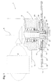
- Fig. 1 shows a device head 2 of a tool device 4 in the form of a hand-held angle grinder.
- the tool device 4 has a spindle-shaped output 6, which can be driven by a motor 8 about a working axis A around.
- a substantially two-part tool holder 10 is held, which has a flange facing away from a housing 12 of the tool unit 4, flange tool receiving means 14 and a housing 12 facing, disc-shaped tool receiving counter-16.
- a disc-shaped tool 18, in particular a cutting disc can be fixed between the tool receiving means 14 and the tool receiving counter-means 16.
- the tool 18, on which, for example, diamond-tipped cutting segments 20 can be provided, has a central bore 22 and six radially spaced-apart through holes 24. These through holes 24 are formed as counterbores, the diameter of which taper continuously in the attached state of the tool 18 shown in the direction of the housing 12. Alternatively, the through holes 24 may be formed as a stepped bore (not shown) with sudden diameter change.
- a generally designated 26 central locking arrangement which is composed essentially of the output 6 of the power tool 4 and a central screw 28.
- the central screw 28 penetrates both a central recess 30 of the tool receiving means 14 and the central bore 22 of the tool 18 and is screwed into a threaded longitudinal bore 32 of the output drive 6.
- a head 34 of the central screw 28 rests against the tool receiving means 14 and pushes this with the interposition of the tool 18 against the tool receiving counter 16.
- coupling means 44 are provided for producing the plug connections 36 on the tool receiving means 14. These each have a formed by a washer molding 38 with a conical peripheral surface 40 and a screwed in a threaded bore 39 screw 42 which holds the molding 38 on the tool receiving means 14, as can be seen in particular from FIG. In this way, the coupling means 44 each form at their free ends a conical portion which tapers away from the tool receiving means 14.
- the conical peripheral surfaces 40 are matched in size and arrangement on the tool receiving means 14 to the size and arrangement of the through holes 28 of the tool 18 and each form a rotation stop. With this rotation stop the coupling means 44 engage in the ready state of the Tool unit 4 in the axial direction loose in the through holes 24 of the tool 18 and form with these in each case an additional eccentric rotational drive.
- the central screw 28 is released from the threaded longitudinal bore 32 and the tool receiving means 14 removed from the output 6. Subsequently, the tool 18 is applied to the tool receiving counter 16.
- an annular shoulder 46 is provided on the tool receiving counter means 16, which has a slightly smaller diameter than the central bore 22 of the tool 18. As a result, the tool 18 can be pushed with the central bore 22 on the annular shoulder 46, by which it is centered with respect to the working axis A.
- the tool receiving means 14 is applied to the tool 18, wherein the coupling means 44 are brought into engagement with the through holes 24.
- the tool receiving means 14 and the tool 18 form the eccentric plug connections 36.
- the circumferential surfaces acting as a rotation stops 40 cooperate in the direction of rotation about the working axis A around the form-fitting with the through holes 24 and thereby allow a high transferable or receivable torque.
- the tool 18 assumes an exactly predetermined position with respect to the tool receiving means 14. In this position, a plurality of groove-shapeddebergleitstoff 48 (see Fig. 3), which are embedded in the radial direction in the tool receiving means 14, arranged so that a flowing in operation along thisdeementleitstoff 48 cooling flow not by contours, such as holes or cutting means of the Tool 18 is disturbed.
- the coupling means 44 only engage loosely in the through-holes.
- the axial securing of the tool 18 and the tool receiving means 14 is therefore carried out only by tightening the central screw 28 on the output. 6
Landscapes
- Engineering & Computer Science (AREA)
- Mechanical Engineering (AREA)
- Life Sciences & Earth Sciences (AREA)
- Wood Science & Technology (AREA)
- Forests & Forestry (AREA)
- Gripping On Spindles (AREA)
- Automatic Tool Replacement In Machine Tools (AREA)
- Constituent Portions Of Griding Lathes, Driving, Sensing And Control (AREA)
- Polishing Bodies And Polishing Tools (AREA)
- Processing Of Stones Or Stones Resemblance Materials (AREA)
Abstract
Description
- Die Erfindung betrifft eine Werkzeugaufnahme für ein scheibenförmiges Werkzeug, wie insbesondere eine Trennscheibe. Die Werkzeugaufnahme weist ein Werkzeugaufnahmemittel und ein Werkzeugaufnahmegegenmittel auf, die von einem motorisch betriebenen Werkzeuggerät um eine Arbeitsachse herum antreibbar sind und zwischen denen das Werkzeug drehfest anbringbar ist. Dabei sind an dem Werkzeug eine Zentralbohrung und wenigstens zwei von dieser beabstandete Durchgangsbohrungen, die jeweils einen sich über die Bohrungslänge sprunghaft oder kontinuierlich verändernden Durchmesser aufweisen, wie Senk- oder Stufenbohrungen, vorgesehen. Zudem weist das Werkzeugaufnahmemittel eine Zentralausnehmung auf, die im angebrachten Zustand des Werkzeugaufnahmemittels von einer zentralen Festlegeanordnung zur axialen Festlegung des Werkzeugaufnahmemittels durchragt wird. Ferner ist am Werkzeugaufnahmemittel wenigstens ein zur Zentralausnehmung beabstandetes Kopplungsmittel vorgesehen. Über dieses Kopplungsmittel ist eine exzentrische Drehmitnahme mit einer der Durchgangsbohrungen der Trennscheibe herstellbar.
- Derartige Werkzeugaufnahmen ermöglichen zwei grundsätzliche Befestigungsarten der Werkzeugscheibe. Bei der ersten Befestigungsart wird die Werkzeugscheibe mittels lediglich einer einzigen Schraube der zentralen Festlegeanordnung an dem Werkzeugaufnahmemittel festgelegt. Hierbei wird die Werkzeugscheibe zwischen dem Werkzeugaufnahmemittel und dem Werkzeugaufnahmegegenmittel form- oder reibschlüssig eingespannt. Diese erste Befestigungsart ermöglicht eine leichte Montage und Demontage der Werkzeugscheibe durch Lösen beziehungsweise Anziehen der zentralen Festlegeanordnung.
- Bei der zweiten Befestigungsart wird die Werkzeugscheibe über mehrere Schrauben an dem dem Werkzeuggerät zugewandten Aufnahmemittel aus Werkzeugaufnahmemittel oder Werkzeugaufnahmegegenmittel festgeschraubt. Die Köpfe dieser Schrauben werden dabei vollständig in den von der Zentralbohrung beabstandeten Senk- oder Stufenbohrungen aufgenommen. Auf diese Weise ragen keine Kopplungsmittel in axialer Richtung an der freien Seite der Werkzeugscheibe ab. Die zweite Befestigungsart ermöglicht somit die Herstellung eines bündigen Schnittes parallel zu einer Fläche, wie beispielsweise einem Boden, einer Wand oder einer Decke. Ferner können bei dieser Befestigungsart wesentlich grössere Drehmomente übertragen beziehungsweise aufgenommen werden.
- Aus der
US 4,870,946 ist eine fluidgekühlte Betonsäge bekannt. Diese weist ein flanschförmiges Werkzeugaufnahmemittel mit einer Zentralausnehmung und mehreren zu dieser beabstandeten Kopplungsmitteln auf. Die Kopplungsmittel weisen in Gewindebohrungen befestigte Senkkopfschrauben auf, deren Senkköpfe beim Festlegen einer Werkzeugscheibe in entsprechende Senkbohrungen verlegt werden, die in die Werkzeugscheibe eingelassen sind. Alternativ hierzu ist eine Befestigung der Werkzeugscheibe über eine äussere Lagerplatte vorgesehen, die über eine Zentralschraube an einem Abtriebsschaft der Betonsäge gehalten wird. Hierdurch wird die Werkzeugscheibe zwischen dem Werkzeugaufnahmemittel und der äusseren Lagerplatte axial festgelegt, wobei die Drehmitnahme der Werkzeugscheibe über einen Stift erfolgt, der vom Werkzeugaufnahmemittel absteht und in eine Öffnung der Werkzeugscheibe greift. - Bei dieser bekannten Werkzeugaufnahme ist für einen normalen Schnittbetrieb neben der hierfür vorgesehenen Befestigung über die Zentralschraube auch eine zusätzliche Befestigung der Werkzeugscheibe über die Kopplungsmittel möglich, um das übertragbare Drehmoment zu erhöhen. Dabei ist jedoch die Anbringung und Entfernung der Werkzeugscheibe wegen der Vielzahl von Schraubverbindungen relativ zeitaufwändig.
- Der vorliegenden Erfindung liegt die Aufgabe zugrunde, bei einer gattungsgemässen Werkzeugaufnahme die genannten Nachteile zu vermeiden und bei einfacher Montierbarkeit beziehungsweise Demontierbarkeit eine hohe Drehmomentaufnahme zwischen dem Werkzeugaufnahmemittel und dem scheibenförmigen Werkzeug zu gewährleisten.
- Erfindungsgemäss wird die Aufgabe dadurch gelöst, dass das wenigstens eine Kopplungsmittel einen Drehanschlag für eine lösbare Steckverbindung mit der wenigstens einen Durchgangsbohrung aufweist, wobei der Drehanschlag hinsichtlich der Arbeitsachse axial lose in eine der Durchgangsbohrungen eingreift. Durch eine derartige axial lösbare Steckverbindung zwischen den Kopplungsmitteln und den Durchgangsbohrungen kann das zwischen dem scheibenförmigen Werkzeug und dem Werkzeugaufnahmemittel aufnehmbare Drehmoment deutlich erhöht werden. Dabei wird durch den Drehanschlag des wenigstens einen Kopplungsmittels ein in Drehrichtung wirksamer Formschluss zwischen dem Werkzeugaufnahmemittel und der Werkzeugscheibe erzeugt. Dieser Formschluss kann wegen des relativ grossen radialen Abstandes zur Arbeitsachse, der als Kraftarm wirkt, ein grosses Drehmoment erzeugen beziehungsweise aufnehmen. Gleichzeitig kann eine derartige Werkzeugaufnahme leicht montiert oder demontiert werden, beispielsweise um eine abgenutzte Werkzeugscheibe auszutauschen. Hierzu muss lediglich die zentrale Festlegeanordnung, die beispielsweise durch eine einzige Schraubverbindung gebildet sein kann, gelöst oder angezogen werden. Die zentrale Festlegeanordnung kann dabei entweder als blosse axiale Sicherung der Werkzeugscheibe oder zusätzlich auch als, beispielsweise reibschlüssige, Drehmitnahme ausgebildet werden. In jedem Fall ist die zentrale Festlegeanordnung so ausgelegt, dass sie den durch die lose Steckverbindung hergestellten Eingriff zwischen den Durchgangsbohrungen und den Kopplungsmitteln bei den im vorgesehenen Betrieb auftretenden Momenten in axialer Richtung sichert.
- In einer besonders bevorzugten Ausführungsform weist das wenigstens eine Kopplungsmittel einen gegenüber dem Werkzeugaufnahmemittel festen oder abnehmbaren Formkörper auf, der mit einer der Durchgangsbohrungen korreliert. Hierdurch kann die Steckverbindung annähernd spielfrei hergestellt werden, wodurch eine maximierte Drehmomentübertragung auf das Werkzeug ermöglicht wird und unnötige Geräuschbildungen verhindert werden. Durch den oder die korrelierenden Formkörper werden dabei zudem die betreffenden Durchgangsbohrungen vollständig ausgefüllt, was wiederum die durch die Durchgangsbohrungen hervorgerufene Materialschwächung teilweise aufhebt und die Steifigkeit des Werkzeuges erhöht. Darüber hinaus wird das Werkzeug durch den Formkörper exakt gegenüber dem Werkzeugaufnahmemittel positioniert. Dies ermöglicht eine hinsichtlich der Strömungsverhältnisse optimierte Anordnung von Kühlwasserleitmitteln des Werkzeugaufnahmemittels gegenüber dem Werkzeug.
- Vorteilhafterweise sind die Durchgangsbohrungen durch Senkbohrungen gebildet und der Formkörper weist an einem freien Ende jeweils einen mit der betreffenden Senkbohrung korrelierenden konischen Abschnitt auf. Hierdurch kann die Steckverbindung zwischen dem Werkzeug und dem Werkzeugaufnahmemittel besonders einfach hergestellt werden, da sich die Formkörper aufgrund ihrer konischen Form in den Senkbohrungen selbst zentrieren und dadurch das gesamte Werkzeug exakt gegenüber dem Werkzeugaufnahmemittel positionieren.
- Bevorzugterweise ist der Formkörper durch eine Unterlegscheibe gebildet, die durch ein Befestigungsmittel am Werkzeugaufnahmemittel festgelegt ist. Hierdurch können die Formkörper einfach hergestellt und beispielsweise mittels handelsüblicher Schrauben an dem Werkzeugaufnahmemittel befestigt werden, was die Herstellungskosten weiter verringert.
- Vorteilhafterweise weist das wenigstens eine Kopplungsmittel hierbei eine Gewindebohrung auf, an der der Formkörper festschraubbar ist. Hierdurch ist es möglich das Werkzeugaufnahmemittel auch ohne oder mit unterschiedlichen Formkörpern zu verwenden. Auf diese Weise kann das Werkzeugaufnahmemittel an verschiedene Betriebsarten beziehungsweise an verschiedene Werkzeugscheiben angepasst werden.
- Ferner sind vorteilhafterweise wenigstens drei, insbesondere sechs, Kopplungsmittel vorgesehen, wodurch um die Arbeitsachse herum eine gleichmässige Drehmomentübertragung vom Werkzeugaufnahmemittel auf das Werkzeug möglich ist.
- Die Erfindung wird nachstehend anhand eines Ausführungsbeispieles näher erläutert. Es zeigen:
- Fig. 1
- einen Schnitt durch einen Gerätekopf eines Werkzeuggerätes mit einer erfindungsgemässen Werkzeugaufnahme,
- Fig. 2
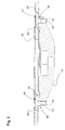
- einen Schnitt durch ein Werkzeugaufnahmemittel der Werkzeugaufnahme nach Fig. 1 und einer mit diesem in Eingriff stehenden Werkzeugscheibe und
- Fig.3
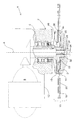
- eine perspektivische Ansicht des Werkzeugaufnahmemittels nach Fig. 2 in Alleinstellung.
- Fig. 1 zeigt einen Gerätekopf 2 eines Werkzeuggerätes 4 in Form eines handgeführten Winkelschleifgerätes. Das Werkzeuggerät 4 weist einen spindelförmigen Abtrieb 6 auf, der von einem Motor 8 um eine Arbeitsachse A herum antreibbar ist. An dem Abtrieb 6 ist dabei eine im Wesentlichen zweiteilige Werkzeugaufnahme 10 gehalten, die ein von einem Gehäuse 12 des Werkzeuggerätes 4 abgewandtes, flanschförmiges Werkzeugaufnahmemittel 14 und ein dem Gehäuse 12 zugewandtes, scheibenförmiges Werkzeugaufnahmegegenmittel 16 aufweist. Zwischen dem Werkzeugaufnahmemittel 14 und dem Werkzeugaufnahmegegenmittel 16 ist dabei, wie dargestellt, ein scheibenförmiges Werkzeug 18, wie insbesondere eine Trennscheibe, festlegbar.
- Das Werkzeug 18, an dem beispielsweise diamantbesetzte Schneidsegmente 20 vorgesehen sein können, weist eine Zentralbohrung 22 sowie sechs gegenüber dieser radial beabstandete Durchgangsbohrungen 24 auf. Diese Durchgangsbohrungen 24 sind als Senkbohrungen ausgebildet, deren Durchmesser sich im gezeigten angebrachten Zustand des Werkzeuges 18 in Richtung des Gehäuses 12 kontinuierlich verjüngen. Alternativ hierzu können die Durchgangsbohrungen 24 auch als Stufenbohrung (nicht dargestellt) mit sprunghafter Durchmesseränderung ausgebildet sein.
- Durch die Zentralbohrung 22 ragt im angebrachten Zustand des Werkzeuges 18 eine insgesamt mit 26 bezeichnete zentrale Festlegeanordnung, die sich im Wesentlichen aus dem Abtrieb 6 des Werkzeuggerätes 4 und einer Zentralschraube 28 zusammensetzt. Die Zentralschraube 28 durchragt dabei sowohl eine Zentralausnehmung 30 des Werkzeugaufnahmemittels 14 als auch die Zentralbohrung 22 des Werkzeuges 18 und ist in eine Gewindelängsbohrung 32 des Abtriebes 6 eingeschraubt. Ein Kopf 34 der Zentralschraube 28 liegt dabei am Werkzeugaufnahmemittel 14 an und drückt dieses unter Zwischenlage des Werkzeuges 18 gegen das Werkzeugaufnahmegegenmittel 16.
- Auf diese Weise wird die axiale Position des Werkzeugaufnahmemittels 14 und des Werkzeuges 18 gesichert und gleichzeitig eine reibschlüssige Drehmitnahme zwischen der Werkzeugscheibe 18 und dem Werkzeugaufnahmemittel 14 und dem Werkzeugaufnahmegegenmittel 16 erzeugt. Zudem wird hierbei an jeder der Durchgangsbohrungen 24 eine hinsichtlich der Arbeitsachse A in axialer Richtung lose Steckverbindung 36 hergestellt.
- Wie insbesondere aus den Fig. 2 und 3 zu entnehmen ist, sind zur Herstellung der Steckverbindungen 36 am Werkzeugaufnahmemittel 14 sechs Kopplungsmittel 44 vorgesehen. Diese weisen jeweils einen durch eine Unterlegscheibe gebildeten Formkörper 38 mit einer konischen Umfangsfläche 40 und eine in einer Gewindebohrung 39 festgeschraubte Schraube 42 auf, die den Formkörper 38 am Werkzeugaufnahmemittel 14 hält, wie insbesondere aus Fig. 2 zu entnehmen ist. Auf diese Weise bilden die Kopplungsmittel 44 an ihren freien Enden jeweils einen konischen Abschnitt aus, der sich von dem Werkzeugaufnahmemittel 14 weg verjüngt.
- Die konischen Umfangsflächen 40 sind in Grösse und Anordnung am Werkzeugaufnahmemittel 14 auf die Grösse und Anordnung der Durchgangsbohrungen 28 des Werkzeuges 18 abgestimmt und bilden jeweils einen Drehanschlag. Mit diesem Drehanschlag greifen die Kopplungsmittel 44 im betriebsbereiten Zustand des Werkzeuggerätes 4 in axialer Richtung lose in die Durchgangsbohrungen 24 des Werkzeuges 18 und bilden mit diesen jeweils eine zusätzliche exzentrische Drehmitnahme.
- Zur Montage des Werkzeuges 18 wird die Zentralschraube 28 von der Gewindelängsbohrung 32 gelöst und das Werkzeugaufnahmemittel 14 vom Abtrieb 6 entfernt. Anschliessend wird das Werkzeug 18 an dem Werkzeugaufnahmegegenmittel 16 angelegt. Um dabei die exakte zentrische Ausrichtung des Werkzeuges 18 zu erleichtern, ist am Werkzeugaufnahmegegenmittel 16 eine Ringschulter 46 vorgesehen, die einen geringfügig kleineren Durchmesser als die Zentralbohrung 22 des Werkzeuges 18 aufweist. Hierdurch kann das Werkzeug 18 mit der Zentralbohrung 22 auf die Ringschulter 46 aufgeschoben werden, durch die sie gegenüber der Arbeitsachse A zentriert wird.
- Sobald das Werkzeug 18 gegenüber der Arbeitsachse A positioniert ist, wird das Werkzeugaufnahmemittel 14 an das Werkzeug 18 angelegt, wobei die Kopplungsmittel 44 mit den Durchgangsbohrungen 24 in Eingriff gebracht werden. Hierdurch bilden das Werkzeugaufnahmemittel 14 und das Werkzeug 18 die exzentrischen Steckverbindungen 36 aus. Die als Drehanschläge fungierenden Umfangsflächen 40 wirken dabei in Drehrichtung um die Arbeitsachse A herum formschlüssig mit den Durchgangsbohrungen 24 zusammen und ermöglichen dadurch ein hohes übertragbares beziehungsweise aufnehmbares Drehmoment. Ferner nimmt das Werkzeug 18 hierbei eine exakt vorbestimmte Position gegenüber dem Werkzeugaufnahmemittel 14 ein. In dieser Position sind mehrere nutförmige Kühlwasserleitmittel 48 (siehe Fig. 3), die in radialer Richtung in das Werkzeugaufnahmemittel 14 eingelassen sind, so angeordnet, dass ein im Betrieb entlang dieser Kühlwasserleitmittel 48 fliessender Kühlstrom nicht durch Konturen, wie beispielsweise Bohrungen oder Schneidmittel, des Werkzeuges 18 gestört wird.
- Entlang der Arbeitsachse A greifen die Kopplungsmittel 44 lediglich lose in die Durchgangsbohrungen ein. Die axiale Sicherung des Werkzeuges 18 und des Werkzeugaufnahmemittels 14 erfolgt daher erst durch Festschrauben der Zentralschraube 28 am Abtrieb 6.
Claims (6)
- Werkzeugaufnahme (10) für ein scheibenförmiges Werkzeug (18)
mit einem Werkzeugaufnahmemittel (14) und einem Werkzeugaufnahmegegenmitte (16),
die um eine Arbeitsachse (A) herum antreibbar sind und zwischen denen das Werkzeug (18) drehfest anbringbar ist,
wobei das Werkzeugaufnahmemittel (14) eine Zentralausnehmung (30), die von einer zentralen Festlegeanordnung (26) durchragbar ist, sowie wenigstens ein zu dieser radial beabstandetes Kopplungsmittel (44) für wenigstens eine Durchgangsbohrung (24) des Werkzeuges (18) aufweist,
dadurch gekennzeichnet, dass das wenigstens eine Kopplungsmittel (44) einen Drehanschlag für eine lösbare Steckverbindung mit der wenigstens einen Durchgangsbohrung (24) aufweist. - Werkzeugaufnahme nach Anspruch 1, dadurch gekennzeichnet, dass das wenigstens eine Kopplungsmittel (44) jeweils einen Formkörper (38) aufweist.
- Werkzeugaufnahme nach Anspruch 2, dadurch gekennzeichnet, dass der Formkörper (38) einen konischen Abschnitt aufweist.
- Werkzeugaufnahme nach Anspruch 2 oder 3, dadurch gekennzeichnet, dass der Formkörper (38) durch eine Unterlegscheibe gebildet ist, die durch ein Befestigungsmittel am Werkzeugaufnahmemittel (14) festgelegt ist.
- Werkzeugaufnahme nach einem der Ansprüche 2 bis 4, dadurch gekennzeichnet, dass das wenigstens eine Kopplungsmittel (44) eine Gewindebohrung (39) aufweist, an der der Formkörper (38) festschraubbar ist
- Werkzeugaufnahme nach einem der Ansprüche 1 bis 5, dadurch gekennzeichnet, dass wenigstens drei Kopplungsmittel (44) vorgesehen sind.
Applications Claiming Priority (1)
| Application Number | Priority Date | Filing Date | Title |
|---|---|---|---|
| DE200610000360 DE102006000360A1 (de) | 2006-07-20 | 2006-07-20 | Werkzeugaufnahme für ein scheibenförmiges Werkzeug |
Publications (3)
| Publication Number | Publication Date |
|---|---|
| EP1880785A2 true EP1880785A2 (de) | 2008-01-23 |
| EP1880785A3 EP1880785A3 (de) | 2011-09-28 |
| EP1880785B1 EP1880785B1 (de) | 2013-04-24 |
Family
ID=38606487
Family Applications (1)
| Application Number | Title | Priority Date | Filing Date |
|---|---|---|---|
| EP20070111806 Active EP1880785B1 (de) | 2006-07-20 | 2007-07-05 | Werkzeugaufnahme für ein scheibenförmiges Werkzeug |
Country Status (5)
| Country | Link |
|---|---|
| US (1) | US7666070B2 (de) |
| EP (1) | EP1880785B1 (de) |
| JP (1) | JP2008023705A (de) |
| CN (1) | CN101108427A (de) |
| DE (1) | DE102006000360A1 (de) |
Cited By (1)
| Publication number | Priority date | Publication date | Assignee | Title |
|---|---|---|---|---|
| EP2929992A1 (de) * | 2014-04-10 | 2015-10-14 | Weber Maschinenbau GmbH Breidenbach | Messer und messeraufnahme für eine schneidemaschine |
Families Citing this family (19)
| Publication number | Priority date | Publication date | Assignee | Title |
|---|---|---|---|---|
| USD623034S1 (en) | 2009-12-18 | 2010-09-07 | Techtronic Power Tools Technology Limited | Tool arbor |
| USD619152S1 (en) | 2009-12-18 | 2010-07-06 | Techtronic Power Tools Technology Limited | Adapter |
| CN101965771B (zh) * | 2010-08-24 | 2012-01-25 | 南京德朔实业有限公司 | 割草机 |
| USD651062S1 (en) | 2010-09-29 | 2011-12-27 | Milwaukee Electric Tool Corporation | Tool interface for an accessory |
| USD653523S1 (en) | 2010-09-29 | 2012-02-07 | Milwaukee Electric Tool Corporation | Adapter for a tool |
| USD646542S1 (en) | 2010-09-29 | 2011-10-11 | Milwaukee Electric Tool Corporation | Accessory interface for a tool |
| CN201931158U (zh) * | 2010-11-30 | 2011-08-17 | 宁波黑松工具有限公司 | 双锯片切割机 |
| CN102423815A (zh) * | 2011-09-08 | 2012-04-25 | 中国人民解放军第四军医大学 | 一种电子专业微型电切锯 |
| US9555554B2 (en) | 2013-05-06 | 2017-01-31 | Milwaukee Electric Tool Corporation | Oscillating multi-tool system |
| CN103722235A (zh) * | 2014-01-22 | 2014-04-16 | 安徽工业大学 | 一种低速金刚石切割机的旋转轴动部件 |
| EP3202533A1 (de) * | 2016-02-02 | 2017-08-09 | HILTI Aktiengesellschaft | Spannvorrichtung |
| CN105772859B (zh) * | 2016-04-25 | 2018-03-06 | 浙江百金机床制造有限公司 | 一种回转式护锯片机构 |
| CN106985033A (zh) * | 2017-04-28 | 2017-07-28 | 中建材(宜兴)新能源有限公司 | 一种用于玻璃深加工生产线磨轮固定装置 |
| CN108131366B (zh) * | 2018-02-08 | 2023-10-13 | 浙江春风动力股份有限公司 | 快拆工具 |
| CN108746830A (zh) * | 2018-06-23 | 2018-11-06 | 汪建文 | 一种自转动式环状剪切装置 |
| CN108942659B (zh) * | 2018-07-27 | 2021-09-03 | 安徽海蚨祥橡胶有限公司 | 包含砂轮夹紧结构的砂轮机 |
| JP7446067B2 (ja) * | 2019-08-22 | 2024-03-08 | 株式会社ディスコ | フランジ機構 |
| JP7688539B2 (ja) * | 2021-08-03 | 2025-06-04 | 株式会社ディスコ | 切削装置 |
| JP7747551B2 (ja) * | 2022-02-25 | 2025-10-01 | 株式会社ディスコ | フランジ、及び、切削方法 |
Family Cites Families (17)
| Publication number | Priority date | Publication date | Assignee | Title |
|---|---|---|---|---|
| US2572042A (en) * | 1948-07-13 | 1951-10-23 | Charles A Martin | Means for mounting cutting blades on shafts |
| FR1147362A (fr) * | 1956-04-14 | 1957-11-22 | Scies circulaires, ou autres outils rotatifs à bois, en plusieurs pièces | |
| US2846826A (en) * | 1957-02-26 | 1958-08-12 | Super Cut | Mounting and truing device for peripheral type circular grinding or cutting wheels |
| FR1421931A (fr) * | 1965-01-22 | 1965-12-17 | Metabowerke K G Closs | Dispositif de serrage, notamment pour scies circulaires à main |
| US3656393A (en) * | 1970-06-19 | 1972-04-18 | Paramount Textile Mach Co | Carbide saw blade locking device |
| US4267759A (en) * | 1979-07-27 | 1981-05-19 | Kimball International, Inc. | Tool safety lock ring |
| US4691685A (en) * | 1985-02-27 | 1987-09-08 | Dempsey Edward J | Sawblade collar assembly |
| US4870946A (en) * | 1987-05-07 | 1989-10-03 | Longco, Inc. | Fluid-cooled apparatus for cutting concrete material and the like |
| US5031364A (en) * | 1989-03-29 | 1991-07-16 | Monogram Industries, Inc. | Fastener pintail shaving tool |
| US6042461A (en) * | 1998-11-10 | 2000-03-28 | Matweld, Inc. | Mounting assembly |
| US6340022B1 (en) * | 1999-10-01 | 2002-01-22 | Daniel J. Schroer | Blade and arbor adaptor for circular saw |
| DE10017457A1 (de) * | 2000-04-07 | 2001-10-11 | Bosch Gmbh Robert | Schleifmaschinenwerkzeugaufnahme |
| DE10017458A1 (de) * | 2000-04-07 | 2001-10-18 | Bosch Gmbh Robert | Schleifmaschinenwerkzeugaufnahme |
| DE10061559A1 (de) * | 2000-12-07 | 2002-06-13 | C & E Fein Gmbh & Co Kg | Aufnahme zur Befestigung eines Werkzeuges an einer Antriebswelle und Adapter hierzu |
| DE10162630A1 (de) * | 2001-12-20 | 2003-07-10 | Hilti Ag | Schleifgerät mit einer Absaughaube |
| US7144315B1 (en) * | 2005-08-05 | 2006-12-05 | Storm Pneumatic Tool Co., Ltd. | Grinding wheel |
| US7186172B1 (en) * | 2006-05-15 | 2007-03-06 | Nao Enterprise, Inc. | Spring force adapter for round blade for a grinder |
-
2006
- 2006-07-20 DE DE200610000360 patent/DE102006000360A1/de not_active Withdrawn
-
2007
- 2007-07-05 EP EP20070111806 patent/EP1880785B1/de active Active
- 2007-07-18 US US11/879,844 patent/US7666070B2/en active Active
- 2007-07-19 JP JP2007188642A patent/JP2008023705A/ja not_active Withdrawn
- 2007-07-19 CN CNA2007101370133A patent/CN101108427A/zh active Pending
Cited By (1)
| Publication number | Priority date | Publication date | Assignee | Title |
|---|---|---|---|---|
| EP2929992A1 (de) * | 2014-04-10 | 2015-10-14 | Weber Maschinenbau GmbH Breidenbach | Messer und messeraufnahme für eine schneidemaschine |
Also Published As
| Publication number | Publication date |
|---|---|
| EP1880785A3 (de) | 2011-09-28 |
| DE102006000360A1 (de) | 2008-01-24 |
| CN101108427A (zh) | 2008-01-23 |
| US7666070B2 (en) | 2010-02-23 |
| US20080017007A1 (en) | 2008-01-24 |
| JP2008023705A (ja) | 2008-02-07 |
| EP1880785B1 (de) | 2013-04-24 |
Similar Documents
| Publication | Publication Date | Title |
|---|---|---|
| EP1880785B1 (de) | Werkzeugaufnahme für ein scheibenförmiges Werkzeug | |
| EP1307313B1 (de) | Handwerkzeugmaschine | |
| DE10038920A1 (de) | Kupplungsvorrichtung für eine Kreissäge | |
| EP2478984B1 (de) | Motorarbeitsgerät mit einer Spanneinrichtung für einen Riemen | |
| EP2826579B1 (de) | Aufnahme für eine Lochsäge und Werkzeuganordnung | |
| EP3411185B1 (de) | Spannvorrichtung | |
| EP0195853A1 (de) | Kupplung für kraftgetriebene Schraubwerkzeuge | |
| DE3913192A1 (de) | Pneumatische oder elektropneumatische starter oder anlasser | |
| DE2106208C3 (de) | ||
| DE102013227216A1 (de) | Verzahntes Bolzensystem zur sichernden Befestigung eines Kreissägeblattes | |
| WO2007087909A1 (de) | Getriebe, insbesondere für elektrohandwerkzeugmaschinen | |
| DE102019112178A1 (de) | Elektrische Servolenkbaugruppe | |
| EP3488971A1 (de) | Elektrisch antreibbare schwenkvorrichtung | |
| DE202018103581U1 (de) | Fräsmaschine, insbesondere Handfräsmaschine zum Fräsen von Fasen und Verrundungen | |
| DE102014014275A1 (de) | Arbeitsgerät | |
| EP0826884B1 (de) | Lüfter | |
| DE688630C (de) | Kupplungsscheibe, insbesondere fuer Kraftfahrzeuge | |
| EP1533091A1 (de) | Spannvorrichtung für ein Werkzeugmaschinen-Bearbeitungselement | |
| DE202013100690U1 (de) | Schneidwerkzeugmaschine | |
| DE102004048916A1 (de) | Zusammengesetzter, beidseitig vorgespannter Bremsring | |
| DE4425961A1 (de) | Planetengetriebe und dessen Verwendung | |
| DE202019103610U1 (de) | Schraubeinheit zum Ausbilden einer reversibel gegen Lösen gesicherten Schraubverbindung | |
| DE3326665C2 (de) | Teilbares Werkzeug für die spanabhebende Bearbeitung | |
| DE102004034119B3 (de) | Webmaschine | |
| DE3830197C1 (en) | Powered screwing tool with a torque-limiting device |
Legal Events
| Date | Code | Title | Description |
|---|---|---|---|
| PUAI | Public reference made under article 153(3) epc to a published international application that has entered the european phase |
Free format text: ORIGINAL CODE: 0009012 |
|
| AK | Designated contracting states |
Kind code of ref document: A2 Designated state(s): AT BE BG CH CY CZ DE DK EE ES FI FR GB GR HU IE IS IT LI LT LU LV MC MT NL PL PT RO SE SI SK TR |
|
| AX | Request for extension of the european patent |
Extension state: AL BA HR MK YU |
|
| PUAL | Search report despatched |
Free format text: ORIGINAL CODE: 0009013 |
|
| AK | Designated contracting states |
Kind code of ref document: A3 Designated state(s): AT BE BG CH CY CZ DE DK EE ES FI FR GB GR HU IE IS IT LI LT LU LV MC MT NL PL PT RO SE SI SK TR |
|
| AX | Request for extension of the european patent |
Extension state: AL BA HR MK RS |
|
| RIC1 | Information provided on ipc code assigned before grant |
Ipc: B27B 5/32 20060101ALI20110819BHEP Ipc: B23B 31/40 20060101AFI20110819BHEP Ipc: B24B 45/00 20060101ALI20110819BHEP |
|
| 17P | Request for examination filed |
Effective date: 20111116 |
|
| AKX | Designation fees paid |
Designated state(s): AT BE BG CH CY CZ DE DK EE ES FI FR GB GR HU IE IS IT LI LT LU LV MC MT NL PL PT RO SE SI SK TR |
|
| 17Q | First examination report despatched |
Effective date: 20120601 |
|
| GRAP | Despatch of communication of intention to grant a patent |
Free format text: ORIGINAL CODE: EPIDOSNIGR1 |
|
| GRAS | Grant fee paid |
Free format text: ORIGINAL CODE: EPIDOSNIGR3 |
|
| GRAA | (expected) grant |
Free format text: ORIGINAL CODE: 0009210 |
|
| AK | Designated contracting states |
Kind code of ref document: B1 Designated state(s): AT BE BG CH CY CZ DE DK EE ES FI FR GB GR HU IE IS IT LI LT LU LV MC MT NL PL PT RO SE SI SK TR |
|
| REG | Reference to a national code |
Ref country code: GB Ref legal event code: FG4D Free format text: NOT ENGLISH |
|
| REG | Reference to a national code |
Ref country code: CH Ref legal event code: EP |
|
| REG | Reference to a national code |
Ref country code: AT Ref legal event code: REF Ref document number: 608290 Country of ref document: AT Kind code of ref document: T Effective date: 20130515 |
|
| REG | Reference to a national code |
Ref country code: IE Ref legal event code: FG4D Free format text: LANGUAGE OF EP DOCUMENT: GERMAN |
|
| REG | Reference to a national code |
Ref country code: DE Ref legal event code: R096 Ref document number: 502007011649 Country of ref document: DE Effective date: 20130620 |
|
| REG | Reference to a national code |
Ref country code: LT Ref legal event code: MG4D |
|
| REG | Reference to a national code |
Ref country code: NL Ref legal event code: VDEP Effective date: 20130424 |
|
| PG25 | Lapsed in a contracting state [announced via postgrant information from national office to epo] |
Ref country code: PT Free format text: LAPSE BECAUSE OF FAILURE TO SUBMIT A TRANSLATION OF THE DESCRIPTION OR TO PAY THE FEE WITHIN THE PRESCRIBED TIME-LIMIT Effective date: 20130826 Ref country code: IS Free format text: LAPSE BECAUSE OF FAILURE TO SUBMIT A TRANSLATION OF THE DESCRIPTION OR TO PAY THE FEE WITHIN THE PRESCRIBED TIME-LIMIT Effective date: 20130824 Ref country code: GR Free format text: LAPSE BECAUSE OF FAILURE TO SUBMIT A TRANSLATION OF THE DESCRIPTION OR TO PAY THE FEE WITHIN THE PRESCRIBED TIME-LIMIT Effective date: 20130725 Ref country code: SI Free format text: LAPSE BECAUSE OF FAILURE TO SUBMIT A TRANSLATION OF THE DESCRIPTION OR TO PAY THE FEE WITHIN THE PRESCRIBED TIME-LIMIT Effective date: 20130424 Ref country code: FI Free format text: LAPSE BECAUSE OF FAILURE TO SUBMIT A TRANSLATION OF THE DESCRIPTION OR TO PAY THE FEE WITHIN THE PRESCRIBED TIME-LIMIT Effective date: 20130424 Ref country code: LT Free format text: LAPSE BECAUSE OF FAILURE TO SUBMIT A TRANSLATION OF THE DESCRIPTION OR TO PAY THE FEE WITHIN THE PRESCRIBED TIME-LIMIT Effective date: 20130424 Ref country code: ES Free format text: LAPSE BECAUSE OF FAILURE TO SUBMIT A TRANSLATION OF THE DESCRIPTION OR TO PAY THE FEE WITHIN THE PRESCRIBED TIME-LIMIT Effective date: 20130804 Ref country code: SE Free format text: LAPSE BECAUSE OF FAILURE TO SUBMIT A TRANSLATION OF THE DESCRIPTION OR TO PAY THE FEE WITHIN THE PRESCRIBED TIME-LIMIT Effective date: 20130424 |
|
| PG25 | Lapsed in a contracting state [announced via postgrant information from national office to epo] |
Ref country code: BG Free format text: LAPSE BECAUSE OF FAILURE TO SUBMIT A TRANSLATION OF THE DESCRIPTION OR TO PAY THE FEE WITHIN THE PRESCRIBED TIME-LIMIT Effective date: 20130724 Ref country code: PL Free format text: LAPSE BECAUSE OF FAILURE TO SUBMIT A TRANSLATION OF THE DESCRIPTION OR TO PAY THE FEE WITHIN THE PRESCRIBED TIME-LIMIT Effective date: 20130424 Ref country code: CY Free format text: LAPSE BECAUSE OF FAILURE TO SUBMIT A TRANSLATION OF THE DESCRIPTION OR TO PAY THE FEE WITHIN THE PRESCRIBED TIME-LIMIT Effective date: 20130424 Ref country code: LV Free format text: LAPSE BECAUSE OF FAILURE TO SUBMIT A TRANSLATION OF THE DESCRIPTION OR TO PAY THE FEE WITHIN THE PRESCRIBED TIME-LIMIT Effective date: 20130424 |
|
| BERE | Be: lapsed |
Owner name: HILTI AKTIENGESELLSCHAFT Effective date: 20130731 |
|
| PG25 | Lapsed in a contracting state [announced via postgrant information from national office to epo] |
Ref country code: CZ Free format text: LAPSE BECAUSE OF FAILURE TO SUBMIT A TRANSLATION OF THE DESCRIPTION OR TO PAY THE FEE WITHIN THE PRESCRIBED TIME-LIMIT Effective date: 20130424 Ref country code: SK Free format text: LAPSE BECAUSE OF FAILURE TO SUBMIT A TRANSLATION OF THE DESCRIPTION OR TO PAY THE FEE WITHIN THE PRESCRIBED TIME-LIMIT Effective date: 20130424 Ref country code: DK Free format text: LAPSE BECAUSE OF FAILURE TO SUBMIT A TRANSLATION OF THE DESCRIPTION OR TO PAY THE FEE WITHIN THE PRESCRIBED TIME-LIMIT Effective date: 20130424 Ref country code: EE Free format text: LAPSE BECAUSE OF FAILURE TO SUBMIT A TRANSLATION OF THE DESCRIPTION OR TO PAY THE FEE WITHIN THE PRESCRIBED TIME-LIMIT Effective date: 20130424 |
|
| PG25 | Lapsed in a contracting state [announced via postgrant information from national office to epo] |
Ref country code: MC Free format text: LAPSE BECAUSE OF FAILURE TO SUBMIT A TRANSLATION OF THE DESCRIPTION OR TO PAY THE FEE WITHIN THE PRESCRIBED TIME-LIMIT Effective date: 20130424 Ref country code: RO Free format text: LAPSE BECAUSE OF FAILURE TO SUBMIT A TRANSLATION OF THE DESCRIPTION OR TO PAY THE FEE WITHIN THE PRESCRIBED TIME-LIMIT Effective date: 20130424 Ref country code: NL Free format text: LAPSE BECAUSE OF FAILURE TO SUBMIT A TRANSLATION OF THE DESCRIPTION OR TO PAY THE FEE WITHIN THE PRESCRIBED TIME-LIMIT Effective date: 20130424 |
|
| PLBE | No opposition filed within time limit |
Free format text: ORIGINAL CODE: 0009261 |
|
| STAA | Information on the status of an ep patent application or granted ep patent |
Free format text: STATUS: NO OPPOSITION FILED WITHIN TIME LIMIT |
|
| 26N | No opposition filed |
Effective date: 20140127 |
|
| REG | Reference to a national code |
Ref country code: IE Ref legal event code: MM4A |
|
| PG25 | Lapsed in a contracting state [announced via postgrant information from national office to epo] |
Ref country code: BE Free format text: LAPSE BECAUSE OF NON-PAYMENT OF DUE FEES Effective date: 20130731 |
|
| REG | Reference to a national code |
Ref country code: DE Ref legal event code: R097 Ref document number: 502007011649 Country of ref document: DE Effective date: 20140127 |
|
| PG25 | Lapsed in a contracting state [announced via postgrant information from national office to epo] |
Ref country code: IE Free format text: LAPSE BECAUSE OF NON-PAYMENT OF DUE FEES Effective date: 20130705 |
|
| REG | Reference to a national code |
Ref country code: AT Ref legal event code: MM01 Ref document number: 608290 Country of ref document: AT Kind code of ref document: T Effective date: 20130705 |
|
| PG25 | Lapsed in a contracting state [announced via postgrant information from national office to epo] |
Ref country code: AT Free format text: LAPSE BECAUSE OF NON-PAYMENT OF DUE FEES Effective date: 20130705 |
|
| PG25 | Lapsed in a contracting state [announced via postgrant information from national office to epo] |
Ref country code: TR Free format text: LAPSE BECAUSE OF FAILURE TO SUBMIT A TRANSLATION OF THE DESCRIPTION OR TO PAY THE FEE WITHIN THE PRESCRIBED TIME-LIMIT Effective date: 20130424 Ref country code: MT Free format text: LAPSE BECAUSE OF FAILURE TO SUBMIT A TRANSLATION OF THE DESCRIPTION OR TO PAY THE FEE WITHIN THE PRESCRIBED TIME-LIMIT Effective date: 20130424 |
|
| PG25 | Lapsed in a contracting state [announced via postgrant information from national office to epo] |
Ref country code: HU Free format text: LAPSE BECAUSE OF FAILURE TO SUBMIT A TRANSLATION OF THE DESCRIPTION OR TO PAY THE FEE WITHIN THE PRESCRIBED TIME-LIMIT; INVALID AB INITIO Effective date: 20070705 Ref country code: LU Free format text: LAPSE BECAUSE OF NON-PAYMENT OF DUE FEES Effective date: 20130705 |
|
| REG | Reference to a national code |
Ref country code: FR Ref legal event code: PLFP Year of fee payment: 10 |
|
| REG | Reference to a national code |
Ref country code: FR Ref legal event code: PLFP Year of fee payment: 11 |
|
| REG | Reference to a national code |
Ref country code: FR Ref legal event code: PLFP Year of fee payment: 12 |
|
| P01 | Opt-out of the competence of the unified patent court (upc) registered |
Effective date: 20230830 |
|
| PGFP | Annual fee paid to national office [announced via postgrant information from national office to epo] |
Ref country code: DE Payment date: 20240719 Year of fee payment: 18 |
|
| PGFP | Annual fee paid to national office [announced via postgrant information from national office to epo] |
Ref country code: GB Payment date: 20240722 Year of fee payment: 18 |
|
| PGFP | Annual fee paid to national office [announced via postgrant information from national office to epo] |
Ref country code: FR Payment date: 20240729 Year of fee payment: 18 |
|
| PGFP | Annual fee paid to national office [announced via postgrant information from national office to epo] |
Ref country code: CH Payment date: 20240801 Year of fee payment: 18 |
|
| PGFP | Annual fee paid to national office [announced via postgrant information from national office to epo] |
Ref country code: IT Payment date: 20240725 Year of fee payment: 18 |
|
| REG | Reference to a national code |
Ref country code: DE Ref legal event code: R119 Ref document number: 502007011649 Country of ref document: DE |
|
| REG | Reference to a national code |
Ref country code: CH Ref legal event code: H13 Free format text: ST27 STATUS EVENT CODE: U-0-0-H10-H13 (AS PROVIDED BY THE NATIONAL OFFICE) Effective date: 20260224 |
|
| GBPC | Gb: european patent ceased through non-payment of renewal fee |
Effective date: 20250705 |
|
| PG25 | Lapsed in a contracting state [announced via postgrant information from national office to epo] |
Ref country code: GB Free format text: LAPSE BECAUSE OF NON-PAYMENT OF DUE FEES Effective date: 20250705 |
|
| PG25 | Lapsed in a contracting state [announced via postgrant information from national office to epo] |
Ref country code: DE Free format text: LAPSE BECAUSE OF NON-PAYMENT OF DUE FEES Effective date: 20260203 |
|
| PG25 | Lapsed in a contracting state [announced via postgrant information from national office to epo] |
Ref country code: FR Free format text: LAPSE BECAUSE OF NON-PAYMENT OF DUE FEES Effective date: 20250731 |
|
| PG25 | Lapsed in a contracting state [announced via postgrant information from national office to epo] |
Ref country code: CH Free format text: LAPSE BECAUSE OF NON-PAYMENT OF DUE FEES Effective date: 20250731 |