EP1879280A1 - A hydroelectric turbine - Google Patents
A hydroelectric turbine Download PDFInfo
- Publication number
- EP1879280A1 EP1879280A1 EP06014667A EP06014667A EP1879280A1 EP 1879280 A1 EP1879280 A1 EP 1879280A1 EP 06014667 A EP06014667 A EP 06014667A EP 06014667 A EP06014667 A EP 06014667A EP 1879280 A1 EP1879280 A1 EP 1879280A1
- Authority
- EP
- European Patent Office
- Prior art keywords
- turbine according
- stator
- coils
- coil
- turbine
- Prior art date
- Legal status (The legal status is an assumption and is not a legal conclusion. Google has not performed a legal analysis and makes no representation as to the accuracy of the status listed.)
- Granted
Links
Images


Classifications
-
- F—MECHANICAL ENGINEERING; LIGHTING; HEATING; WEAPONS; BLASTING
- F03—MACHINES OR ENGINES FOR LIQUIDS; WIND, SPRING, OR WEIGHT MOTORS; PRODUCING MECHANICAL POWER OR A REACTIVE PROPULSIVE THRUST, NOT OTHERWISE PROVIDED FOR
- F03B—MACHINES OR ENGINES FOR LIQUIDS
- F03B13/00—Adaptations of machines or engines for special use; Combinations of machines or engines with driving or driven apparatus; Power stations or aggregates
- F03B13/08—Machine or engine aggregates in dams or the like; Conduits therefor, e.g. diffusors
- F03B13/083—The generator rotor being mounted as turbine rotor rim
-
- H—ELECTRICITY
- H02—GENERATION; CONVERSION OR DISTRIBUTION OF ELECTRIC POWER
- H02K—DYNAMO-ELECTRIC MACHINES
- H02K7/00—Arrangements for handling mechanical energy structurally associated with dynamo-electric machines, e.g. structural association with mechanical driving motors or auxiliary dynamo-electric machines
- H02K7/10—Structural association with clutches, brakes, gears, pulleys or mechanical starters
-
- H—ELECTRICITY
- H02—GENERATION; CONVERSION OR DISTRIBUTION OF ELECTRIC POWER
- H02K—DYNAMO-ELECTRIC MACHINES
- H02K11/00—Structural association of dynamo-electric machines with electric components or with devices for shielding, monitoring or protection
- H02K11/04—Structural association of dynamo-electric machines with electric components or with devices for shielding, monitoring or protection for rectification
- H02K11/049—Rectifiers associated with stationary parts, e.g. stator cores
- H02K11/05—Rectifiers associated with casings, enclosures or brackets
-
- H—ELECTRICITY
- H02—GENERATION; CONVERSION OR DISTRIBUTION OF ELECTRIC POWER
- H02K—DYNAMO-ELECTRIC MACHINES
- H02K3/00—Details of windings
- H02K3/04—Windings characterised by the conductor shape, form or construction, e.g. with bar conductors
- H02K3/28—Layout of windings or of connections between windings
-
- H—ELECTRICITY
- H02—GENERATION; CONVERSION OR DISTRIBUTION OF ELECTRIC POWER
- H02K—DYNAMO-ELECTRIC MACHINES
- H02K3/00—Details of windings
- H02K3/46—Fastening of windings on the stator or rotor structure
- H02K3/47—Air-gap windings, i.e. iron-free windings
-
- H—ELECTRICITY
- H02—GENERATION; CONVERSION OR DISTRIBUTION OF ELECTRIC POWER
- H02K—DYNAMO-ELECTRIC MACHINES
- H02K7/00—Arrangements for handling mechanical energy structurally associated with dynamo-electric machines, e.g. structural association with mechanical driving motors or auxiliary dynamo-electric machines
- H02K7/18—Structural association of electric generators with mechanical driving motors, e.g. with turbines
- H02K7/1807—Rotary generators
- H02K7/1823—Rotary generators structurally associated with turbines or similar engines
-
- F—MECHANICAL ENGINEERING; LIGHTING; HEATING; WEAPONS; BLASTING
- F05—INDEXING SCHEMES RELATING TO ENGINES OR PUMPS IN VARIOUS SUBCLASSES OF CLASSES F01-F04
- F05B—INDEXING SCHEME RELATING TO WIND, SPRING, WEIGHT, INERTIA OR LIKE MOTORS, TO MACHINES OR ENGINES FOR LIQUIDS COVERED BY SUBCLASSES F03B, F03D AND F03G
- F05B2220/00—Application
- F05B2220/70—Application in combination with
- F05B2220/706—Application in combination with an electrical generator
- F05B2220/7064—Application in combination with an electrical generator of the alternating current (A.C.) type
-
- F—MECHANICAL ENGINEERING; LIGHTING; HEATING; WEAPONS; BLASTING
- F05—INDEXING SCHEMES RELATING TO ENGINES OR PUMPS IN VARIOUS SUBCLASSES OF CLASSES F01-F04
- F05B—INDEXING SCHEME RELATING TO WIND, SPRING, WEIGHT, INERTIA OR LIKE MOTORS, TO MACHINES OR ENGINES FOR LIQUIDS COVERED BY SUBCLASSES F03B, F03D AND F03G
- F05B2240/00—Components
- F05B2240/10—Stators
- F05B2240/13—Stators to collect or cause flow towards or away from turbines
- F05B2240/133—Stators to collect or cause flow towards or away from turbines with a convergent-divergent guiding structure, e.g. a Venturi conduit
-
- H—ELECTRICITY
- H02—GENERATION; CONVERSION OR DISTRIBUTION OF ELECTRIC POWER
- H02K—DYNAMO-ELECTRIC MACHINES
- H02K11/00—Structural association of dynamo-electric machines with electric components or with devices for shielding, monitoring or protection
- H02K11/04—Structural association of dynamo-electric machines with electric components or with devices for shielding, monitoring or protection for rectification
- H02K11/049—Rectifiers associated with stationary parts, e.g. stator cores
-
- H—ELECTRICITY
- H02—GENERATION; CONVERSION OR DISTRIBUTION OF ELECTRIC POWER
- H02K—DYNAMO-ELECTRIC MACHINES
- H02K16/00—Machines with more than one rotor or stator
- H02K16/02—Machines with one stator and two or more rotors
-
- H—ELECTRICITY
- H02—GENERATION; CONVERSION OR DISTRIBUTION OF ELECTRIC POWER
- H02K—DYNAMO-ELECTRIC MACHINES
- H02K21/00—Synchronous motors having permanent magnets; Synchronous generators having permanent magnets
- H02K21/12—Synchronous motors having permanent magnets; Synchronous generators having permanent magnets with stationary armatures and rotating magnets
- H02K21/14—Synchronous motors having permanent magnets; Synchronous generators having permanent magnets with stationary armatures and rotating magnets with magnets rotating within the armatures
-
- H—ELECTRICITY
- H02—GENERATION; CONVERSION OR DISTRIBUTION OF ELECTRIC POWER
- H02K—DYNAMO-ELECTRIC MACHINES
- H02K7/00—Arrangements for handling mechanical energy structurally associated with dynamo-electric machines, e.g. structural association with mechanical driving motors or auxiliary dynamo-electric machines
- H02K7/18—Structural association of electric generators with mechanical driving motors, e.g. with turbines
-
- Y—GENERAL TAGGING OF NEW TECHNOLOGICAL DEVELOPMENTS; GENERAL TAGGING OF CROSS-SECTIONAL TECHNOLOGIES SPANNING OVER SEVERAL SECTIONS OF THE IPC; TECHNICAL SUBJECTS COVERED BY FORMER USPC CROSS-REFERENCE ART COLLECTIONS [XRACs] AND DIGESTS
- Y02—TECHNOLOGIES OR APPLICATIONS FOR MITIGATION OR ADAPTATION AGAINST CLIMATE CHANGE
- Y02E—REDUCTION OF GREENHOUSE GAS [GHG] EMISSIONS, RELATED TO ENERGY GENERATION, TRANSMISSION OR DISTRIBUTION
- Y02E10/00—Energy generation through renewable energy sources
- Y02E10/20—Hydro energy
-
- Y—GENERAL TAGGING OF NEW TECHNOLOGICAL DEVELOPMENTS; GENERAL TAGGING OF CROSS-SECTIONAL TECHNOLOGIES SPANNING OVER SEVERAL SECTIONS OF THE IPC; TECHNICAL SUBJECTS COVERED BY FORMER USPC CROSS-REFERENCE ART COLLECTIONS [XRACs] AND DIGESTS
- Y02—TECHNOLOGIES OR APPLICATIONS FOR MITIGATION OR ADAPTATION AGAINST CLIMATE CHANGE
- Y02E—REDUCTION OF GREENHOUSE GAS [GHG] EMISSIONS, RELATED TO ENERGY GENERATION, TRANSMISSION OR DISTRIBUTION
- Y02E10/00—Energy generation through renewable energy sources
- Y02E10/30—Energy from the sea, e.g. using wave energy or salinity gradient
Definitions
- the present invention is concerned with a hydroelectric turbine for the generation of electricity, and in particular to an open-centre hydroelectric turbine adapted to generate electricity from ocean currents and/or tidal streams.
- Power take off from an open-centre hydroelectric turbine is most conveniently arranged by means of an electrical generator of rim construction located at the outer edge of the rotor and inner edge of the stator.
- the generator is a synchronous machine of high pole number.
- the field system may use electrical coils supplied with current or a set of permanent magnets to provide the magneto motive force required to drive magnetic flux through the magnetic circuit. This arrangement gives a large diameter open space in the centre of the stator that accommodates the rotor.
- the rim generator operates at the same rotational speed as the turbine and requires no gearing.
- Directly-Driven (i.e. gearless) Generators with Permanent-Magnet field excitation offer the simplest and potentially most reliable and cost-effective form of power take-off device for renewable energy systems.
- the majority of DDPMG designs employ a magnetic circuit created by a set of magnets on the rotor forming a radial magnetic field within a narrow gap separating the rotor and stator.
- the stator is usually of essentially conventional construction and includes an electrical circuit based on insulated coils intertwined within slots in the bore of a cylindrical laminated iron stator and resembles the stator of an induction or synchronous machine.
- the magnetic circuit is coupled to the electrical circuit by virtue of the location of the rotor within the stator.
- the magnetic circuit normally includes ferromagnetic sections made of iron or steel to provide a path of low reluctance for the passage of magnetic flux. Such sections are usually provided within both the rotor and stator.
- the magnetic field established by the field system passes across the gap that separates the rotor and stator. Relative movement of the rotor, and therefore magnetic field, with respect to the stator, and therefore the stator coils of the electric circuit, causes an electromotive force (EMF) to be induced in the coils. However, the flux linkage with any other circuit within the stator also undergoes changing flux linkage and emf is induced.
- EMF electromotive force
- the core of the stator onto which the coils are wound, from thin sheets of magnetic iron or steel separated by electrical insulation. The sheets are called laminations and are cut to shape by a punching process.
- Insulation is usually provided by a thin coating to one or both sides of the sheet from which the lamination is punched.
- the armature coils are usually attached to the laminated magnetic core by forming slots during the punching process. The coils have to be inserted and secured in the slots and this process stresses the winding insulation, and often means that thicker insulation is needed than would be required simply for electrical isolation.
- the cost of producing the die for punching the laminations can be an important component of the final machine cost and the time taken to make the special die can delay construction.
- the material removed from the centre of the punched lamination is wasted, which represents a considerable cost.
- the present invention has therefore been developed with a view to mitigating the above mentioned problems.
- the present invention therefore provides a hydroelectric turbine comprising a rotor; an array of magnets disposed about an outer rim of the rotor and forming a radial magnetic field; a slotless stator concentrically surrounding the rotor; and a plurality of coils on the stator.
- the stator comprises an annular ferromagnetic wire winding which defines a magnetic flux return path for the magnets.
- the coils are disposed radially inwardly of the wire winding.
- the individual coils are mechanically attached to the stator without being intertwined therewith.
- the coils are not intertwined with one another.
- the coils are arranged side by side to define an annular array concentrically surrounding the array of magnets.
- the induced electromotive force in the coils are not all of the same phase.
- each coil is bonded to the stator.
- each coil is wound along a substantially obround path.
- each coil is provided with a dedicated rectifier.
- the rectifiers are mounted on the stator.
- each rectifier is mounted in close proximity to the respective coil.
- each coil is encased in a fluid tight coating or housing.
- each coil and respective rectifier are encased together in a fluid tight coating or housing.
- the coating or housing is electrically insulating.
- each rectifier comprises a diode bridge or half bridge.
- the rectifiers feed to a common DC output.
- the rectifiers are connected together to form a plurality of groups in each of which the rectifiers are connected in parallel, the plurality of groups being connected together in series.
- the stator winding is formed from non-insulated wire.
- slotless is intended to refer to the configuration of the stator of an electric generator, and in particular the absence of the conventional slots formed about the inner edge of the bore of cylindrical laminated iron core, and through which slots insulated copper coils are conventionally wound.
- a hydroelectric turbine for use in generating electricity, primarily from tidal currents and/or ocean currents, although the turbine 10 may have other applications, for example within a hydroelectric dam (not shown) or the like.
- the turbine 10 embodies a number of distinct benefits over prior art equivalents, in particular improved reliability, lower costs, and a lighter weight construction.
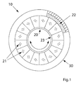
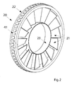
- the turbine 10 comprises a rotor 20 housed for rotation within a stator 30.
- the rotor 20 is of an open centre design, and includes an inner rim 23 which defines said open centre.
- the rotor 20 further comprises an array of generally radially extending blades 21 captured between the inner rim 23 and an outer rim 22.
- the rotor 20 further comprises an array of magnets 41, preferably permanent magnets, disposed about the outer rim 22.
- the magnets 41 are polarised alternately north and south in the circumferential direction.
- the array of magnets 41 are preferably seated on an annular ring (not shown) of ferromagnetic material.
- the stator 30, in cross section, defines a venturi, at the throat of which is provided an annular channel 32 in which, in use, the rotor 20 is seated.
- the venturi cross section of the stator 30 effects acceleration of water flowing through the stator 30, in order to increase the speed of rotation of the rotor 20.
- This venturi cross section is not however essential to the operation of the invention.
- Any suitable form of bearings may be provided between the rotor 20 and the stator 30, in order to facilitate the smooth running of the rotor 20.
- the stator 30 may be formed from any suitable material, and in the preferred embodiment illustrated, is formed substantially from GRP.
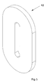
- annular array of individual coils 42 Fixed to the stator 30, within the channel 32, is an annular array of individual coils 42, an example of one of which is illustrated in Figure 5. The configuration and operation of the array of coils 42 will be described in greater detail hereinafter.
- the winding 50 provides, in use, a magnetic flux return path on the stator 30 for the magnetic fields generated by the magnets 41, in addition to preferably providing structural strength to the stator 30. This further facilitates the use of lightweight material in the production of the stator 30.
- the rotor 20 is seated within the channel 32 of the stator 30, and thus the coils 42 concentrically surround the magnets 41, with a relatively narrow gap therebetween.
- this gap is known as the airgap, but during operation the turbine 10 is submersed under water, and thus the gap is filled with water as opposed to air.
- the magnets 41 generate a radially extending magnetic field which crosses the gap between the outer rim 22 and the stator 30, with the winding 50 forming the magnetic flux return path.
- the radially extending magnetic field which preferably alternates between north and south between adjacent magnets 41, will cut through the coils 42, inducing an alternating EMF in each coil 42. It is these induced AC EMF's that provide the electrical power output from the turbine 10, as will be described hereinafter in detail.
- the stator 30 employs a wire winding 50 in place of the conventional slotted and laminated stator arrangement, in order to provide the magnetic flux return path for the magnetic field generated by the magnets 41.
- This arrangement has been found to have a number of beneficial results, which are particularly advantageous when used in hydroelectric applications.
- "Cogging” is a phenomenon experienced in motors/generators having a conventional slotted stator arrangement, whereby the rotor magnets seek alignment with the stator teeth, resulting in the rotor being attracted towards a preferred position.
- stator 30 significantly reduces the cost and complexity of stator 30, while the use of the wire winding 50 is relatively inexpensive and straightforward to produce.
- a further advantage arises from the placement of the winding 50 radially outwardly of the array of coils 42. This configuration creates a larger gap for the magnetic flux to cross from the magnets 41, thus reducing the magnetic flux density across said gap. While this would initially appear as a disadvantage, it does result in a reduced attraction force between the stator 30 and rotor 20. This reduces the required stiffness of the rotor 20 and stator 30 in order to resist said attractive force, and thus resist deformation.
- the rotor 20 and stator 30 can be produced as relatively lightweight components, significantly reducing the cost of same, while simplifying the transport and manoeuvring of same.
- This can be a significant benefit given the overall dimensions of the turbine 10, which may be approximately 10 metres or greater in diameter.
- the use of the iron wire winding 50 further eliminates waste during the production of same, which is a significant factor when producing slotted laminated windings, in particular for large scale machines such as the turbine 10.
- the coils in which EMF is induced are conventionally wound in complex overlapping patterns to form a web surrounding the rotor. These coils are normally configured to provide a three-phase AC output.
- a slotless armature it is conventional practice to provide some form of frame or loom on which to wind the above-mentioned coils.
- the present invention however provides an entirely different and significantly improved configuration for the electrical circuit of the turbine 10. Referring in particular to Figures 3 and 4, it can be seen that the electrical circuit consists of a large number of the coils 42 arranged side by side in an annular array within the channel 24.
- each coil 42 may vary depending on the requirements of the turbine 10.
- each coil 42 is provided with its own rectifier 71, preferably a single phase bridge rectifier 71 (shown only in the Figure 6 circuit diagram), such that the induced AC current in each coil 42 is immediately rectified to DC, with the output from each combined coil 42 and rectifier 71 then being connected to a common DC output for the turbine 10.
- rectifier 71 preferably a single phase bridge rectifier 71 (shown only in the Figure 6 circuit diagram)
- An alternative circuit could use a half bridge rectifier (not shown) for each coil 42.
- each rectifier would comprise a pair of diodes one of which is connected between one terminal of the respective coil and the positive dc output terminal and the other diode connected between the same terminal of the coil and the negative dc output terminal, with the other terminal of the coil being connected to a common point to which all the other coils are connected.
- the coils 42 are preferably of insulated copper wire or rectangular strip wound around an obround or "race track” path, for ease of construction and to provide the necessary length of copper wire in each coil 42 which is perpendicularly cut by the magnetic field of the rotor 20.
- the coils 42 preferably have an electrically insulating core or form (not shown) of generally elongate rectangular shape, onto and around which the copper wire or strip is wound in order to provide the "race track" shape.
- the number of turns in each coil 42 can be selected such that the voltage generated is less than the rating of commercially available, and preferably low cost, rectifiers 71, even if the rotor 20 speeds up to it's maximum due to disconnection of the load (not shown) being supplied by the turbine.
- the use of the simple diode based rectifiers 71 has also been facilitated by recognising that the winding 50 has a significantly lower reactance than a conventional laminated slotted armature, enabling the diode based rectifiers 71 to be used without incurring unacceptable voltage drop in the impedance of the coils 42.
- This arrangement of a dedicated rectifier 71 for each coil 42 positioned alongside or in close proximity to the coil 42, enables the first AC to DC conversion stage of an AC-DC-AC conversion system to be carried out at the turbine 10, with the power then being transmitted as DC to a convenient location for the final conversion back to three phase AC at fixed voltage and frequency for grid connection.
- each of the coils 42 is provided as a physically separate unit, which therefore enables each coil 42 to be produced off site, and thus accurately yet inexpensively.
- the coils 42 can also be coated in electrical insulation (not shown) preferably in the form of a resin in which the coils 42 can be dipped or otherwise coated or housed. This coating or casing preferably provides electrical insulation of the coils 42 from earth or ground.
- the dedicated rectifier 71 for each coil 42 can be electrically connected, in series, to the coil 42, and positioned alongside same, in order to be simultaneously coated in the resin, and thus be effectively physically integrated with the coil 42 as a single unit.
- the coated coil 42 and rectifier 71 then resembles a relatively thin rectangular slab with a simple two wire output (not shown) projecting from same.
- the process for producing a single coil 42 and rectifier 71 unit could be used to produce a group of coils 42 with their associated rectifiers 71 to form a module in the form of a short arc.
- This arrangement has a number of benefits compared with the conventional arrangement in which coils are connected to produce a three phase output which is passed to a separate three phase rectifier circuit, namely:
- each coil 42 is then connected to a common DC output for the turbine 10, as will be described in greater detail below.
- Each coil 42 is preferably mounted such as to be disposed in a plane which is substantially tangential to the point on the channel 32 against which the coil 42 is mounted.
- the electrically insulating coating of each coil 42 and associated rectifier 71 is also preferably adapted to provide a hermetic seal thereabout, enabling the turbine 10 to be submersed under water.
- each coil 42 is simultaneously electrically insulated and hermetically sealed during the offsite manufacture of same, thereby eliminating further sealing once the coils 42 are installed on the stator 30. This again simplifies the assembly of the turbine 10, and reduces the cost of same.
- the precision to which the combined coil 42 and rectifier 71 unit can be manufactured is also greatly increased by this separate manufacturing process. In particular the units can be manufactured under clean conditions, and if necessary utilising vacuum pressure impregnation facilities.
- FIG. 6 there is illustrated a circuit diagram representing the electric circuit of the stator 30 as defined by the plurality of coils 42 and associated rectifiers 71.
- the number of coils 42 included in the circuit diagram of Figure 6 is not necessarily representative of the number of coils 42 which may actually be provided on the stator 30.
- the circuit diagram illustrated is intended only to show a preferred configuration for the connections between the coils 42 and rectifiers 71, and it should be appreciated that any other suitable configuration may be employed. It can be seen that in the preferred embodiment illustrated, the array of coils 42, and thus the respective rectifiers 71, are arranged in four series groups, each group including seven coils 42 connected in parallel to one another.
- the number of coils 42 in each group, and the number of groups chosen, is dictated by the desired voltage and/or current at the common DC output.
- the number of coil / rectifier units 30 in parallel will dictate the total current, while the number of groups in series will dictate the total voltage.
- the arrangement may vary depending on the number of coils 42 forming part of the turbine 10, and the voltage and/or current generated within each coil 42, which will be dependent on a number of factors, not least the magnetic flux density cutting through each coil 42, and the number of turns in each coil 42.
- the desired voltage and current at the common DC output for the turbine 10 may also be varied depending on the application in question.
- the turbine 10 may be provided as part of a tidal farm including a plurality of the turbines 10 whose outputs are connected in parallel, to a common cable 72 for feeding power back to shore or any other desired location.
- a high voltage DC input inverter 73 is preferably provided for the purpose of feeding the power into a utility grid or the like.
- the turbine 10 may be configured to generate a lower voltage DC, for example 1000V to 1500V, and final conversion to AC for grid connection may be by an inverter (not shown) similar to those used in electrical drive applications.
Abstract
Description
- The present invention is concerned with a hydroelectric turbine for the generation of electricity, and in particular to an open-centre hydroelectric turbine adapted to generate electricity from ocean currents and/or tidal streams.
- Power take off from an open-centre hydroelectric turbine is most conveniently arranged by means of an electrical generator of rim construction located at the outer edge of the rotor and inner edge of the stator. In such cases the generator is a synchronous machine of high pole number. The field system may use electrical coils supplied with current or a set of permanent magnets to provide the magneto motive force required to drive magnetic flux through the magnetic circuit. This arrangement gives a large diameter open space in the centre of the stator that accommodates the rotor. The rim generator operates at the same rotational speed as the turbine and requires no gearing.
- Directly-Driven (i.e. gearless) Generators with Permanent-Magnet field excitation (DDPMGs) offer the simplest and potentially most reliable and cost-effective form of power take-off device for renewable energy systems.
- The majority of DDPMG designs employ a magnetic circuit created by a set of magnets on the rotor forming a radial magnetic field within a narrow gap separating the rotor and stator. The stator is usually of essentially conventional construction and includes an electrical circuit based on insulated coils intertwined within slots in the bore of a cylindrical laminated iron stator and resembles the stator of an induction or synchronous machine. The magnetic circuit is coupled to the electrical circuit by virtue of the location of the rotor within the stator. The magnetic circuit normally includes ferromagnetic sections made of iron or steel to provide a path of low reluctance for the passage of magnetic flux. Such sections are usually provided within both the rotor and stator.
- The magnetic field established by the field system passes across the gap that separates the rotor and stator. Relative movement of the rotor, and therefore magnetic field, with respect to the stator, and therefore the stator coils of the electric circuit, causes an electromotive force (EMF) to be induced in the coils. However, the flux linkage with any other circuit within the stator also undergoes changing flux linkage and emf is induced. In order to avoid unwanted current flowing in the magnetic iron or steel of the stator, which results in power loss, it is usual to construct the core of the stator, onto which the coils are wound, from thin sheets of magnetic iron or steel separated by electrical insulation. The sheets are called laminations and are cut to shape by a punching process. Insulation is usually provided by a thin coating to one or both sides of the sheet from which the lamination is punched. The armature coils are usually attached to the laminated magnetic core by forming slots during the punching process. The coils have to be inserted and secured in the slots and this process stresses the winding insulation, and often means that thicker insulation is needed than would be required simply for electrical isolation.
- Where small numbers of machines are required the cost of producing the die for punching the laminations can be an important component of the final machine cost and the time taken to make the special die can delay construction. In addition, the material removed from the centre of the punched lamination is wasted, which represents a considerable cost.
- In hyrdoelectric applications it is desirable to use a large-diameter machine, which can lead to improved efficiency and reduced use of electromagnetically-active material. However, for machines of large diameter it is necessary to construct the laminations as a set of arc segments, because it is not possible to obtain magnetic steel sheet in sufficient size for producing a complete ring. The arcs must be housed in a supporting structure. This adds significant cost to the machine.
- This laminated, slotted stator arrangement results in the formation of teeth which project towards the rotor, thus resulting in the rotor being attracted toward a preferred angular position, an effect known as "cogging", which then requires considerable drive torque to start the rotor. Furthermore, the large radial attraction force between rotor and stator requires a massive stiff supporting structure.
- The present invention has therefore been developed with a view to mitigating the above mentioned problems.
- The present invention therefore provides a hydroelectric turbine comprising a rotor; an array of magnets disposed about an outer rim of the rotor and forming a radial magnetic field; a slotless stator concentrically surrounding the rotor; and a plurality of coils on the stator.
- Preferably, the stator comprises an annular ferromagnetic wire winding which defines a magnetic flux return path for the magnets.
- Preferably, the coils are disposed radially inwardly of the wire winding.
- Preferably, the individual coils are mechanically attached to the stator without being intertwined therewith.
- Preferably, the coils are not intertwined with one another.
- Preferably, the coils are arranged side by side to define an annular array concentrically surrounding the array of magnets.
- Preferably, the induced electromotive force in the coils are not all of the same phase.
- Preferably, each coil is bonded to the stator.
- Preferably, each coil is wound along a substantially obround path.
- Preferably, each coil is provided with a dedicated rectifier.
- Preferably, the rectifiers are mounted on the stator.
- Preferably, each rectifier is mounted in close proximity to the respective coil.
- Preferably, each coil is encased in a fluid tight coating or housing.
- Preferably, each coil and respective rectifier are encased together in a fluid tight coating or housing.
- Preferably, the coating or housing is electrically insulating.
- Preferably, each rectifier comprises a diode bridge or half bridge.
- Preferably, the rectifiers feed to a common DC output.
- Preferably, the rectifiers are connected together to form a plurality of groups in each of which the rectifiers are connected in parallel, the plurality of groups being connected together in series.
- Preferably, the stator winding is formed from non-insulated wire.
- As used herein, the term "slotless" is intended to refer to the configuration of the stator of an electric generator, and in particular the absence of the conventional slots formed about the inner edge of the bore of cylindrical laminated iron core, and through which slots insulated copper coils are conventionally wound.
- The present invention will now be described with reference to the accompanying drawings, in which;
- Figure 1 illustrates a perspective view of a hydroelectric turbine according to a preferred embodiment of the present invention;
- Figure 2 illustrates a perspective view of a rotor forming part of the hydroelectric turbine of the present invention;
- Figure 3 illustrates a perspective view of a stator forming a further part of the hydroelectric turbine of the invention;
- Figure 4 illustrates a sectioned view of the stator of Figure 2;
- Figure 5 illustrates a perspective view of a coil forming part of the turbine of the present invention;
- Figure 6 illustrates a circuit diagram of the array of coils forming part of the turbine of the present invention; and
- Figure 7 illustrates a schematic illustration of a tidal farm containing a plurality of the hydroelectric turbines of the present invention.
- Referring now to the accompanying drawings, there is illustrated a hydroelectric turbine, generally indicated as 10, for use in generating electricity, primarily from tidal currents and/or ocean currents, although the
turbine 10 may have other applications, for example within a hydroelectric dam (not shown) or the like. As will become clear from the following description, theturbine 10 embodies a number of distinct benefits over prior art equivalents, in particular improved reliability, lower costs, and a lighter weight construction. - Referring in particular to Figure 2, the
turbine 10 comprises arotor 20 housed for rotation within astator 30. Therotor 20 is of an open centre design, and includes aninner rim 23 which defines said open centre. Therotor 20 further comprises an array of generally radially extendingblades 21 captured between theinner rim 23 and anouter rim 22. Therotor 20 further comprises an array ofmagnets 41, preferably permanent magnets, disposed about theouter rim 22. Themagnets 41 are polarised alternately north and south in the circumferential direction. The array ofmagnets 41 are preferably seated on an annular ring (not shown) of ferromagnetic material. - Referring now to Figures 3 and 4, it can be seen that the
stator 30, in cross section, defines a venturi, at the throat of which is provided anannular channel 32 in which, in use, therotor 20 is seated. The venturi cross section of thestator 30 effects acceleration of water flowing through thestator 30, in order to increase the speed of rotation of therotor 20. This venturi cross section is not however essential to the operation of the invention. Any suitable form of bearings may be provided between therotor 20 and thestator 30, in order to facilitate the smooth running of therotor 20. As with therotor 20, thestator 30 may be formed from any suitable material, and in the preferred embodiment illustrated, is formed substantially from GRP. - Fixed to the
stator 30, within thechannel 32, is an annular array ofindividual coils 42, an example of one of which is illustrated in Figure 5. The configuration and operation of the array ofcoils 42 will be described in greater detail hereinafter. Wound concentrically about the array ofcoils 42, radially outwardly thereof, is a ferromagnetic winding 50, preferably formed from iron wire. The winding 50 provides, in use, a magnetic flux return path on thestator 30 for the magnetic fields generated by themagnets 41, in addition to preferably providing structural strength to thestator 30. This further facilitates the use of lightweight material in the production of thestator 30. - In use, the
rotor 20 is seated within thechannel 32 of thestator 30, and thus thecoils 42 concentrically surround themagnets 41, with a relatively narrow gap therebetween. In a conventional electric motor/generator, this gap is known as the airgap, but during operation theturbine 10 is submersed under water, and thus the gap is filled with water as opposed to air. Themagnets 41 generate a radially extending magnetic field which crosses the gap between theouter rim 22 and thestator 30, with the winding 50 forming the magnetic flux return path. As water flows through theturbine 10, effecting rotation of therotor 20, the radially extending magnetic field, which preferably alternates between north and south betweenadjacent magnets 41, will cut through thecoils 42, inducing an alternating EMF in eachcoil 42. It is these induced AC EMF's that provide the electrical power output from theturbine 10, as will be described hereinafter in detail. - As mentioned above, the
stator 30 employs a wire winding 50 in place of the conventional slotted and laminated stator arrangement, in order to provide the magnetic flux return path for the magnetic field generated by themagnets 41.
This arrangement has been found to have a number of beneficial results, which are particularly advantageous when used in hydroelectric applications. The absence of a slotted and laminated iron core, or more particularly the inclusion of the unbroken annular winding 50, eliminates "cogging" of therotor 20. "Cogging" is a phenomenon experienced in motors/generators having a conventional slotted stator arrangement, whereby the rotor magnets seek alignment with the stator teeth, resulting in the rotor being attracted towards a preferred position. This phenomenon thus results in an increase in the start-up torque of such conventional motors/generators. By eliminating this "cogging" via the inclusion of the slotless winding 50, therotor 20 has a lowered start-up torque, and is therefore capable of starting in low velocity flows, as would be found in tidal applications, which will not generate much torque in therotor 20. In addition, theturbine 10 can extract power over the full tidal cycle. - Furthermore, the omission of the slotted and laminated stator arrangement significantly reduces the cost and complexity of
stator 30, while the use of the wire winding 50 is relatively inexpensive and straightforward to produce. A further advantage arises from the placement of the winding 50 radially outwardly of the array ofcoils 42. This configuration creates a larger gap for the magnetic flux to cross from themagnets 41, thus reducing the magnetic flux density across said gap. While this would initially appear as a disadvantage, it does result in a reduced attraction force between thestator 30 androtor 20. This reduces the required stiffness of therotor 20 andstator 30 in order to resist said attractive force, and thus resist deformation. As a result, therotor 20 andstator 30 can be produced as relatively lightweight components, significantly reducing the cost of same, while simplifying the transport and manoeuvring of same. This can be a significant benefit given the overall dimensions of theturbine 10, which may be approximately 10 metres or greater in diameter. The use of the iron wire winding 50 further eliminates waste during the production of same, which is a significant factor when producing slotted laminated windings, in particular for large scale machines such as theturbine 10. - Regardless of the type of armature employed in electric generators/motors, the coils in which EMF is induced, and which are generally formed of copper wire, are conventionally wound in complex overlapping patterns to form a web surrounding the rotor. These coils are normally configured to provide a three-phase AC output. In the case of a slotless armature, it is conventional practice to provide some form of frame or loom on which to wind the above-mentioned coils. The present invention however provides an entirely different and significantly improved configuration for the electrical circuit of the
turbine 10. Referring in particular to Figures 3 and 4, it can be seen that the electrical circuit consists of a large number of thecoils 42 arranged side by side in an annular array within the channel 24. The number ofcoils 42 may vary depending on the requirements of theturbine 10. In addition, eachcoil 42 is provided with itsown rectifier 71, preferably a single phase bridge rectifier 71 (shown only in the Figure 6 circuit diagram), such that the induced AC current in eachcoil 42 is immediately rectified to DC, with the output from each combinedcoil 42 andrectifier 71 then being connected to a common DC output for theturbine 10. The above-mentioned features have proven to be significantly advantageous, in particular for hydroelectric applications, the reasons for which are set out hereinafter. An alternative circuit (not shown) could use a half bridge rectifier (not shown) for eachcoil 42. With such an arrangement each rectifier would comprise a pair of diodes one of which is connected between one terminal of the respective coil and the positive dc output terminal and the other diode connected between the same terminal of the coil and the negative dc output terminal, with the other terminal of the coil being connected to a common point to which all the other coils are connected. - The
coils 42 are preferably of insulated copper wire or rectangular strip wound around an obround or "race track" path, for ease of construction and to provide the necessary length of copper wire in eachcoil 42 which is perpendicularly cut by the magnetic field of therotor 20. Thecoils 42 preferably have an electrically insulating core or form (not shown) of generally elongate rectangular shape, onto and around which the copper wire or strip is wound in order to provide the "race track" shape. The number of turns in eachcoil 42 can be selected such that the voltage generated is less than the rating of commercially available, and preferably low cost,rectifiers 71, even if therotor 20 speeds up to it's maximum due to disconnection of the load (not shown) being supplied by the turbine. The use of the simple diode basedrectifiers 71 has also been facilitated by recognising that the winding 50 has a significantly lower reactance than a conventional laminated slotted armature, enabling the diode basedrectifiers 71 to be used without incurring unacceptable voltage drop in the impedance of thecoils 42. This arrangement of adedicated rectifier 71 for eachcoil 42, positioned alongside or in close proximity to thecoil 42, enables the first AC to DC conversion stage of an AC-DC-AC conversion system to be carried out at theturbine 10, with the power then being transmitted as DC to a convenient location for the final conversion back to three phase AC at fixed voltage and frequency for grid connection. - As the
coils 42 are not provided as a complex web intertwined about thestator 30, the cost and complexity of producing the electric circuit of thestator 30 is significantly reduced. In particular, each of thecoils 42 is provided as a physically separate unit, which therefore enables eachcoil 42 to be produced off site, and thus accurately yet inexpensively. During manufacture, thecoils 42 can also be coated in electrical insulation (not shown) preferably in the form of a resin in which thecoils 42 can be dipped or otherwise coated or housed. This coating or casing preferably provides electrical insulation of thecoils 42 from earth or ground. - Further advantageously, during this insulating process, the
dedicated rectifier 71 for eachcoil 42 can be electrically connected, in series, to thecoil 42, and positioned alongside same, in order to be simultaneously coated in the resin, and thus be effectively physically integrated with thecoil 42 as a single unit. Thecoated coil 42 andrectifier 71 then resembles a relatively thin rectangular slab with a simple two wire output (not shown) projecting from same. Similarly the process for producing asingle coil 42 andrectifier 71 unit could be used to produce a group ofcoils 42 with their associatedrectifiers 71 to form a module in the form of a short arc. Again such a module could be produced separately from theoverall turbine 10, and preferably under clean conditions, and if required using vacuum pressure impregnation facilities that would have to be impractically large and expensive if used to produce a full annular array of thecoils 42 for theentire turbine 10. - This arrangement has a number of benefits compared with the conventional arrangement in which coils are connected to produce a three phase output which is passed to a separate three phase rectifier circuit, namely:
- The conventional interconnections between the coils are eliminated
- The
rectifiers 71 isolate anycoil 42 that suffers a fault, allowing the remaininghealthy coils 42 to operate - The cost is lower than a conventional arrangement due to the use of mass produced low cost
single phase rectifiers 71 compared with more highly rated components for a separate single full power three phase rectifier - The single
phase bridge rectifier 71 located alongside eachcoil 42 can be integrated in such a way that it shares in the cooling arrangement provided for thecoils 42 so that separate rectifier cooling provision is unnecessary - Each
coil 42 may be wound with two or more conductors in parallel in order to reduce the size of conductor required so that eddy currents within the conductor and the resulting loss are kept to an acceptable level. In such cases each conductor of thecoil 42 may be given a separate rectifier bridge. In the event of the failure of one conductor or its rectifier, the other conductors of thecoil 42 may continue to operate - Mounting the array of
coils 42 to thestator 30 is then a simple task of adhering the resin-coatedcoils 42 in side by side alignment within thechannel 32, in order to create the annular array illustrated. This is fundamentally different to the conventional configuration of coil windings on a slotted stator, which requires a complex winding pattern to be employed. It will thus be appreciated that unlike in a conventional winding arrangement, theindividual coils 42 are not intertwined with thestator 30, or more particularly the winding 50 providing the magnetic flux return path , nor are they intertwined with one another. This arrangement significantly reduces the complexity of producing thefinished stator 30, thus reducing the time and cost of manufacturing same. - The output from each
coil 42 is then connected to a common DC output for theturbine 10, as will be described in greater detail below. Eachcoil 42 is preferably mounted such as to be disposed in a plane which is substantially tangential to the point on thechannel 32 against which thecoil 42 is mounted. The electrically insulating coating of eachcoil 42 and associatedrectifier 71 is also preferably adapted to provide a hermetic seal thereabout, enabling theturbine 10 to be submersed under water. Thus eachcoil 42 is simultaneously electrically insulated and hermetically sealed during the offsite manufacture of same, thereby eliminating further sealing once thecoils 42 are installed on thestator 30. This again simplifies the assembly of theturbine 10, and reduces the cost of same. The precision to which the combinedcoil 42 andrectifier 71 unit can be manufactured is also greatly increased by this separate manufacturing process. In particular the units can be manufactured under clean conditions, and if necessary utilising vacuum pressure impregnation facilities. - Referring then to Figure 6, there is illustrated a circuit diagram representing the electric circuit of the
stator 30 as defined by the plurality ofcoils 42 and associatedrectifiers 71. It will however be appreciated that the number ofcoils 42 included in the circuit diagram of Figure 6 is not necessarily representative of the number ofcoils 42 which may actually be provided on thestator 30. In addition, the circuit diagram illustrated is intended only to show a preferred configuration for the connections between thecoils 42 andrectifiers 71, and it should be appreciated that any other suitable configuration may be employed. It can be seen that in the preferred embodiment illustrated, the array ofcoils 42, and thus therespective rectifiers 71, are arranged in four series groups, each group including sevencoils 42 connected in parallel to one another. The number ofcoils 42 in each group, and the number of groups chosen, is dictated by the desired voltage and/or current at the common DC output. Thus the number of coil /rectifier units 30 in parallel will dictate the total current, while the number of groups in series will dictate the total voltage. The arrangement may vary depending on the number ofcoils 42 forming part of theturbine 10, and the voltage and/or current generated within eachcoil 42, which will be dependent on a number of factors, not least the magnetic flux density cutting through eachcoil 42, and the number of turns in eachcoil 42. The desired voltage and current at the common DC output for theturbine 10 may also be varied depending on the application in question. For example, if theturbine 10 is located offshore, and must transmit the power generated along a five kilometre stretch of subterranean cable, it is likely that a voltage in the range of 10,000 volts would be required, in order to drive the current along this length of cable in order to avoid unacceptable power loss in a cable of economical cross section. - It will be appreciated from Figure 6 that the use of a large array of
coils 42, connected in the configuration illustrated, ensures a high degree of redundancy of thecoils 42. Thus if aparticular coil 42 or associated rectified 71 was to fail, the overall effect on the power generating capabilities of theturbine 10 would be relatively small, and in any event would not prevent the continuing operation of theturbine 10. Furthermore, the use of a large number of thecoils 42 provides a smooth DC output because the EMF from thecoils 42 are not all of the same phase. - Referring to Figure 7, the
turbine 10 may be provided as part of a tidal farm including a plurality of theturbines 10 whose outputs are connected in parallel, to acommon cable 72 for feeding power back to shore or any other desired location. For the purpose of feeding the power into a utility grid or the like, a high voltageDC input inverter 73 is preferably provided. If the transmission distance is shorter, theturbine 10 may be configured to generate a lower voltage DC, for example 1000V to 1500V, and final conversion to AC for grid connection may be by an inverter (not shown) similar to those used in electrical drive applications.
Claims (19)
- A hydroelectric turbine comprising a rotor; an array of magnets disposed about an outer rim of the rotor and forming a radial magnetic field; a slotless stator concentrically surrounding the rotor; and a plurality of coils on the stator.
- A turbine according to claim 1 in which the stator comprises a ferromagnetic wire winding which defines a magnetic flux return path for the magnets.
- A turbine according to claim 2 in which the coils are disposed radially inwardly of the wire winding.
- A turbine according to any preceding claim in which the individual coils are mechanically attached to the stator without being intertwined therewith.
- A turbine according to any preceding claim in which the coils are not intertwined with one another.
- A turbine according to any preceding claim in which the coils are arranged side by side to define an annular array concentrically surrounding the array of magnets.
- A turbine according to any preceding claim in which the induced electromotive force in the coils are not all of the same phase.
- A turbine according to any preceding claim in which each coil is bonded to the stator.
- A turbine according to any preceding claim in which each coil is wound along a substantially obround path.
- A turbine according to any preceding claim in which each coil is provided with a dedicated rectifier.
- A turbine according to claim 10 in which the rectifiers are mounted on the stator.
- A turbine according to any preceding claim in which each rectifier is mounted in close proximity to the respective coil.
- A turbine according to any preceding claim in which each coil is encased in a fluid tight coating or housing.
- A turbine according to any of claims 10 to 13 in which each coil and respective rectifier are encased together in a fluid tight coating or housing.
- A turbine according to claim 13 or 14 in which the coating or housing is electrically insulating.
- A turbine according to any of claims 10 to 15 in which each rectifier comprises a diode bridge or half bridge.
- A turbine according to any of claims 10 to 16 in which the rectifiers are connected to a common DC output.
- A turbine according to any of claims 10 to 17 in which the rectifiers are connected together to form a plurality of groups in each of which the rectifiers are connected in parallel, the plurality of groups being connected together in series.
- A turbine according to any of claims 2 to 18 in which the stator winding is formed from non-insulated iron wire.
Priority Applications (13)
| Application Number | Priority Date | Filing Date | Title |
|---|---|---|---|
| EP06014667.7A EP1879280B1 (en) | 2006-07-14 | 2006-07-14 | A hydroelectric turbine |
| MYPI20090162 MY150390A (en) | 2006-07-14 | 2007-07-13 | A hydroelectric turbine |
| NZ574053A NZ574053A (en) | 2006-07-14 | 2007-07-13 | A hydroelectric turbine with a rotor housed concentrically within a slotless stator |
| PCT/EP2007/006258 WO2008006614A1 (en) | 2006-07-14 | 2007-07-13 | A hydroelectric turbine |
| JP2009519844A JP5084828B2 (en) | 2006-07-14 | 2007-07-13 | Hydroelectric turbine |
| US12/373,489 US8466595B2 (en) | 2006-07-14 | 2007-07-13 | Hydroelectric turbine |
| AU2007271907A AU2007271907B2 (en) | 2006-07-14 | 2007-07-13 | A hydroelectric turbine |
| CA2658203A CA2658203C (en) | 2006-07-14 | 2007-07-13 | A hydroelectric turbine |
| CN2007800267114A CN101507088B (en) | 2006-07-14 | 2007-07-13 | A hydroelectric turbine |
| KR1020097003016A KR101454008B1 (en) | 2006-07-14 | 2007-07-13 | Hydroelectric turbine |
| RU2009104363/07A RU2009104363A (en) | 2006-07-14 | 2007-07-13 | HYDROELECTRIC TURBINE |
| NO20090687A NO338368B1 (en) | 2006-07-14 | 2009-02-12 | Hydroelectric turbine |
| RU2013117743A RU2621667C2 (en) | 2006-07-14 | 2013-04-18 | Hydroelectric turbine |
Applications Claiming Priority (1)
| Application Number | Priority Date | Filing Date | Title |
|---|---|---|---|
| EP06014667.7A EP1879280B1 (en) | 2006-07-14 | 2006-07-14 | A hydroelectric turbine |
Publications (2)
| Publication Number | Publication Date |
|---|---|
| EP1879280A1 true EP1879280A1 (en) | 2008-01-16 |
| EP1879280B1 EP1879280B1 (en) | 2014-03-05 |
Family
ID=37606863
Family Applications (1)
| Application Number | Title | Priority Date | Filing Date |
|---|---|---|---|
| EP06014667.7A Not-in-force EP1879280B1 (en) | 2006-07-14 | 2006-07-14 | A hydroelectric turbine |
Country Status (12)
| Country | Link |
|---|---|
| US (1) | US8466595B2 (en) |
| EP (1) | EP1879280B1 (en) |
| JP (1) | JP5084828B2 (en) |
| KR (1) | KR101454008B1 (en) |
| CN (1) | CN101507088B (en) |
| AU (1) | AU2007271907B2 (en) |
| CA (1) | CA2658203C (en) |
| MY (1) | MY150390A (en) |
| NO (1) | NO338368B1 (en) |
| NZ (1) | NZ574053A (en) |
| RU (2) | RU2009104363A (en) |
| WO (1) | WO2008006614A1 (en) |
Cited By (16)
| Publication number | Priority date | Publication date | Assignee | Title |
|---|---|---|---|---|
| GB2445822A (en) * | 2006-10-13 | 2008-07-23 | Borealis Tech Ltd | Blade tip driven gas turbine engine starter/generator |
| WO2008081187A3 (en) * | 2007-01-04 | 2008-10-02 | Power Ltd C | Tidal electricity generating apparatus |
| EP2112370A1 (en) | 2008-04-22 | 2009-10-28 | OpenHydro Group Limited | A hydro-electric turbine having a magnetic bearing |
| EP2199599A1 (en) | 2008-12-18 | 2010-06-23 | OpenHydro IP Limited | A hydroelectric turbine with a debris expeller |
| EP2302766A2 (en) * | 2009-09-29 | 2011-03-30 | OpenHydro IP Limited | A hydroelectric turbine with coil cooling |
| EP2302755A1 (en) * | 2009-09-29 | 2011-03-30 | OpenHydro IP Limited | An electrical power conversion system and method |
| US8308422B2 (en) | 2006-07-14 | 2012-11-13 | Openhydro Group Limited | Submerged hydroelectric turbines having buoyancy chambers |
| US8466595B2 (en) | 2006-07-14 | 2013-06-18 | Openhydro Group Limited | Hydroelectric turbine |
| US8596964B2 (en) | 2006-07-14 | 2013-12-03 | Openhydro Group Limited | Turbines having a debris release chute |
| US8659180B2 (en) | 2007-08-24 | 2014-02-25 | Fourivers Power Engineering Pty Ltd. | Power generation apparatus |
| EP2704297A1 (en) * | 2012-08-28 | 2014-03-05 | GE Energy Power Conversion Technology Ltd | DC electrical machines |
| AU2012216624B2 (en) * | 2008-08-22 | 2014-04-17 | 4Rivers Power Engineering Pty Ltd | Power Generation Apparatus |
| GB2513286A (en) * | 2012-10-25 | 2014-10-29 | G A R & D Ltd | Apparatus |
| WO2014199183A2 (en) * | 2013-06-14 | 2014-12-18 | Ve Energy Limited | Generator assembly |
| US9765647B2 (en) | 2010-11-09 | 2017-09-19 | Openhydro Ip Limited | Hydroelectric turbine recovery system and a method therefor |
| US11456643B2 (en) * | 2018-10-02 | 2022-09-27 | Denso Corporation | Rotating electric machine, controller, vehicle system, and maintenance method of rotating electric machine |
Families Citing this family (46)
| Publication number | Priority date | Publication date | Assignee | Title |
|---|---|---|---|---|
| EP1878913B1 (en) | 2006-07-14 | 2013-03-13 | OpenHydro Group Limited | Bi-directional tidal flow hydroelectric turbine |
| DE602007007294D1 (en) | 2007-04-11 | 2010-08-05 | Openhydro Group Ltd | Method for installing hydroelectric turbines |
| ATE480035T1 (en) * | 2007-12-12 | 2010-09-15 | Openhydro Group Ltd | GENERATOR COMPONENT FOR A HYDROELECTRIC TURBINE |
| EP2088311B1 (en) | 2008-02-05 | 2015-10-14 | OpenHydro Group Limited | A hydroelectric turbine with floating rotor |
| EP2110910A1 (en) | 2008-04-17 | 2009-10-21 | OpenHydro Group Limited | An improved turbine installation method |
| WO2010025560A1 (en) | 2008-09-03 | 2010-03-11 | Exro Technologies Inc. | Power conversion system for a multi-stage generator |
| ATE556218T1 (en) | 2008-12-18 | 2012-05-15 | Openhydro Ip Ltd | HYDROELECTRIC TURBINE WITH PASSIVE BRAKE AND METHOD OF OPERATION |
| EP2199603A1 (en) | 2008-12-19 | 2010-06-23 | OpenHydro IP Limited | A method of controlling the output of a hydroelectric turbine generator |
| DE602008002602D1 (en) | 2008-12-19 | 2010-10-28 | Openhydro Ip Ltd | Method for installing a hydroelectric turbine generator |
| EP2200170A1 (en) | 2008-12-19 | 2010-06-23 | OpenHydro IP Limited | A system for braking and isolation of a hydroelectric turbine generator |
| US20120001435A1 (en) * | 2009-03-10 | 2012-01-05 | Colin Richard Pearce | Generator power conditioning |
| ATE548562T1 (en) | 2009-04-17 | 2012-03-15 | Openhydro Ip Ltd | IMPROVED METHOD FOR CONTROLLING THE OUTPUT OF A HYDROELECTRIC TURBINE GENERATOR |
| BR112012004808A2 (en) | 2009-09-03 | 2018-03-13 | Exro Tech Inc | variable coil configuration system, apparatus and method |
| EP2302204A1 (en) * | 2009-09-29 | 2011-03-30 | OpenHydro IP Limited | A hydroelectric turbine system |
| CN102597498A (en) | 2009-10-29 | 2012-07-18 | 海洋能源公司 | Energy conversion systems and methods |
| DE102010018804A1 (en) * | 2010-04-29 | 2011-11-03 | Voith Patent Gmbh | water turbine |
| BR112012027846A2 (en) | 2010-04-30 | 2018-05-15 | Clean Current Lp | unidirectional hydraulic turbine with improved duct, blades and generator |
| EP2403111B1 (en) * | 2010-06-29 | 2017-05-17 | Siemens Aktiengesellschaft | Generator, wind turbine, method of assembling a generator and use of a generator in a wind turbine |
| NO331710B1 (en) * | 2010-07-09 | 2012-03-05 | Smartmotor As | Electric machine for underwater applications and energy conversion system. |
| KR101269880B1 (en) * | 2010-10-26 | 2013-06-07 | 주식회사 이잰 | small hydro power generating apparatus |
| EP2469257B1 (en) | 2010-12-23 | 2014-02-26 | Openhydro IP Limited | A hydroelectric turbine testing method |
| EP2557662B1 (en) * | 2011-08-10 | 2017-05-31 | Openhydro IP Limited | A hydroelectric turbine coil arrangement |
| KR101264872B1 (en) * | 2011-10-14 | 2013-05-30 | (주)파워이에프씨 | Water power generator |
| CN102720626B (en) * | 2012-06-26 | 2015-06-24 | 张珩 | Wave power generation device used in shallow water area |
| CN106163839B (en) * | 2014-03-12 | 2019-03-19 | 哈金森公司 | Hydraulic antivibration device equipped with power generator and the power generator for the vibration abatement |
| GB2524782B (en) * | 2014-04-02 | 2016-04-20 | Verderg Ltd | Turbine assembly |
| EP3149323B1 (en) * | 2014-05-30 | 2022-04-20 | Oceana Energy Company | Hydroelectric turbines, anchoring structures, and related methods of assembly |
| GB201417734D0 (en) * | 2014-10-07 | 2014-11-19 | Tendeka As | Turbine |
| US20160281679A1 (en) * | 2015-01-29 | 2016-09-29 | Donald Wichers | Fluid driven electric power generation system |
| RU2742012C2 (en) * | 2015-02-12 | 2021-02-01 | Хайдроукайнетик Энерджи Корп | Unidirectional hydrokinetic turbine (variants) and enclosure for such a turbine |
| WO2016173602A1 (en) * | 2015-04-27 | 2016-11-03 | Ingenieurbüro Kurt Stähle | Hydroelectric power plant having a free-standing axis of rotation |
| WO2017029869A1 (en) * | 2015-08-20 | 2017-02-23 | 株式会社コベルコ科研 | Subsea buoy |
| KR102384670B1 (en) * | 2015-10-22 | 2022-04-07 | 오세아나 에너지 컴퍼니 | Hydroelectric energy systems and related components and methods |
| KR101638147B1 (en) * | 2015-12-22 | 2016-07-25 | 주식회사 에스에이치지 | Water turbine and waterturbing generator using the same |
| KR101638142B1 (en) * | 2015-12-22 | 2016-07-14 | 주식회사 에스에이치지 | Water turbine and waterturbing generator using the same |
| CN109565232B (en) * | 2016-08-05 | 2021-02-05 | 日本电产株式会社 | Motor |
| US10734912B2 (en) * | 2016-08-24 | 2020-08-04 | Beckhoff Automation Gmbh | Stator device for a linear motor, linear drive system, and method for operating a stator device |
| US11081996B2 (en) | 2017-05-23 | 2021-08-03 | Dpm Technologies Inc. | Variable coil configuration system control, apparatus and method |
| CN111936742B (en) * | 2018-03-28 | 2023-04-04 | 航空电机工程有限公司 | Self-propelled thrust-generating control moment gyroscope |
| BR112021014004A2 (en) | 2019-01-18 | 2021-09-21 | Telesystem Energy Ltd. | PASSIVE MAGNETIC BEARING AND TURBINE FOR IMPLEMENTATION WITHIN AN OPERATING ENVIRONMENT |
| CN113316443A (en) | 2019-01-20 | 2021-08-27 | 航空电机有限责任公司 | Medical stabilizer banding method and apparatus |
| KR20210138680A (en) | 2019-03-14 | 2021-11-19 | 텔레시스템 에너지 리미티드 | Multi-stage cowl for hydrodynamic turbines |
| KR102060701B1 (en) * | 2019-03-18 | 2019-12-30 | 양정환 | A Mocular Ultra-light DC Generator |
| US11722026B2 (en) | 2019-04-23 | 2023-08-08 | Dpm Technologies Inc. | Fault tolerant rotating electric machine |
| EP4315556A1 (en) | 2021-05-04 | 2024-02-07 | Exro Technologies Inc. | Battery control systems and methods |
| WO2022236424A1 (en) | 2021-05-13 | 2022-11-17 | Exro Technologies Inc. | Method and appartus to drive coils of a multiphase electric machine |
Citations (6)
| Publication number | Priority date | Publication date | Assignee | Title |
|---|---|---|---|---|
| GB924347A (en) | 1961-02-23 | 1963-04-24 | Licentia Gmbh | A direct-current miniature motor |
| US4720640A (en) | 1985-09-23 | 1988-01-19 | Turbostar, Inc. | Fluid powered electrical generator |
| WO2002099950A1 (en) | 2001-06-06 | 2002-12-12 | Evolving Generation Limited | Rotor and electrical generator |
| US6957947B2 (en) | 2003-08-05 | 2005-10-25 | Herbert Lehman Williams | Hydroelectric turbine |
| JP2006094645A (en) * | 2004-09-24 | 2006-04-06 | Univ Kansai | Revolving-field type synchronous generator and wind power generation device using permanent magnet |
| EP1876350A1 (en) | 2005-04-11 | 2008-01-09 | Maria Elena Nova Vidal | Electric power generator system using ring-shaped generators |
Family Cites Families (155)
| Publication number | Priority date | Publication date | Assignee | Title |
|---|---|---|---|---|
| US2054142A (en) | 1936-09-15 | Scalable adjustable blade hydraulic | ||
| GB204505A (en) | 1922-09-07 | 1923-10-04 | Thomas Mccormac Adair | Improvements in connection with turbines for utilizing tides or currents for producing electricity and for other purposes |
| CH146935A (en) | 1930-06-28 | 1931-05-15 | Schuetz Alois | Device on turbines and pumps with impellers without an outer ring for removing foreign bodies that are trapped between the housing and the outer edge of the blades. |
| US2563279A (en) | 1946-01-11 | 1951-08-07 | Wallace E Rushing | Wind turbine |
| US2501696A (en) | 1946-01-12 | 1950-03-28 | Wolfgang Kmentt | Stream turbine |
| US2470797A (en) | 1946-04-19 | 1949-05-24 | Percy H Thomas | Aerogenerator |
| CH260699A (en) | 1946-11-14 | 1949-03-31 | Alsthom Cgee | Umbrella type vertical axis hydraulic generator. |
| US2658453A (en) | 1950-07-22 | 1953-11-10 | Pacific Pumps Inc | Nonclogging pumping device |
| US2782321A (en) | 1952-04-30 | 1957-02-19 | Fischer Arno | Turbine for driving a generator |
| US2792505A (en) | 1956-01-27 | 1957-05-14 | Westinghouse Electric Corp | Water wheel generator assembly |
| US3209156A (en) | 1962-04-03 | 1965-09-28 | Jr Arthur D Struble | Underwater generator |
| DK102285C (en) | 1962-11-30 | 1965-08-02 | Morten Lassen-Nielsen | Method for lowering large structures through deep water for laying on the bottom. |
| US3355998A (en) | 1964-07-24 | 1967-12-05 | Allen V Roemisch | Highway marker device |
| US3292023A (en) * | 1964-09-03 | 1966-12-13 | Garrett Corp | Dynamoelectric machine |
| GB1099346A (en) | 1964-10-30 | 1968-01-17 | English Electric Co Ltd | Improvements in or relating to water turbines pumps and reversible pump turbines |
| US3342444A (en) | 1965-07-12 | 1967-09-19 | Allen W Key | Post stabilizer |
| US3384787A (en) | 1965-07-15 | 1968-05-21 | Dole Valve Co | Integrated solenoid coil and rectifier assembly |
| GB1131352A (en) | 1966-04-05 | 1968-10-23 | Clevedon Electronics Ltd | Improvements relating to motor control circuits |
| US3487805A (en) | 1966-12-22 | 1970-01-06 | Satterthwaite James G | Peripheral journal propeller drive |
| NL6908353A (en) | 1968-07-01 | 1970-01-05 | ||
| US3477236A (en) | 1968-11-12 | 1969-11-11 | Combustion Eng | Surface to subsea guidance system |
| DE2163256A1 (en) | 1971-12-20 | 1973-07-26 | Maschf Augsburg Nuernberg Ag | FLOW MACHINE, IN PARTICULAR TURB PUMP, OR FLOW MEASUREMENT DEVICE FOR AN AGGRESSIVE, RADIOACTIVE OR CLEAN FLUID |
| US3986787A (en) | 1974-05-07 | 1976-10-19 | Mouton Jr William J | River turbine |
| US3987638A (en) | 1974-10-09 | 1976-10-26 | Exxon Production Research Company | Subsea structure and method for installing the structure and recovering the structure from the sea floor |
| US4095918A (en) | 1975-10-15 | 1978-06-20 | Mouton Jr William J | Turbine wheel with catenary blades |
| US4163904A (en) | 1976-03-04 | 1979-08-07 | Lawrence Skendrovic | Understream turbine plant |
| US4219303A (en) | 1977-10-27 | 1980-08-26 | Mouton William J Jr | Submarine turbine power plant |
| US4274009A (en) * | 1977-11-25 | 1981-06-16 | Parker Sr George | Submerged hydroelectric power generation |
| US4367413A (en) * | 1980-06-02 | 1983-01-04 | Ramon Nair | Combined turbine and generator |
| US4541367A (en) | 1980-09-25 | 1985-09-17 | Owen, Wickersham & Erickson, P.C. | Combustion and pollution control system |
| DE3116740A1 (en) | 1981-04-28 | 1982-11-11 | Eugen 7000 Stuttgart Gravemeyer | Wave-power generating plant |
| US4523878A (en) | 1981-08-27 | 1985-06-18 | Exxon Production Research Co. | Remotely replaceable guidepost method and apparatus |
| CH655529B (en) | 1981-09-29 | 1986-04-30 | ||
| US4427897A (en) | 1982-01-18 | 1984-01-24 | John Midyette, III | Fixed pitch wind turbine system utilizing aerodynamic stall |
| US4613762A (en) | 1984-12-11 | 1986-09-23 | The United States Of America As Represented By The Secretary Of Agriculture | Output responsive field control for wind-driven alternators and generators |
| US4868970A (en) * | 1985-03-08 | 1989-09-26 | Kolimorgen Corporation | Method of making an electric motor |
| US4740711A (en) | 1985-11-29 | 1988-04-26 | Fuji Electric Co., Ltd. | Pipeline built-in electric power generating set |
| JPS62160047A (en) * | 1985-12-30 | 1987-07-16 | Mitsuba Electric Mfg Co Ltd | Flat motor |
| DE3638129A1 (en) | 1986-11-08 | 1988-05-11 | Licentia Gmbh | Large diameter turbogenerator for generating electrical energy at high power |
| DE3718954A1 (en) | 1987-06-05 | 1988-12-22 | Uwe Gartmann | Propeller arrangement, in particular for ship propulsion plants |
| US4868408A (en) | 1988-09-12 | 1989-09-19 | Frank Hesh | Portable water-powered electric generator |
| US4990810A (en) | 1989-07-18 | 1991-02-05 | Westinghouse Electric Corp. | Coil carrier fixture and field coil carrier assembly |
| US5656880A (en) * | 1993-02-17 | 1997-08-12 | Cadac Limited | Discoidal dynamo-electric machine |
| US5606791A (en) * | 1993-09-17 | 1997-03-04 | Fougere; Richard J. | Method of making a slotless electric motor or transducer |
| US5495221A (en) | 1994-03-09 | 1996-02-27 | The Regents Of The University Of California | Dynamically stable magnetic suspension/bearing system |
| US5592816A (en) | 1995-02-03 | 1997-01-14 | Williams; Herbert L. | Hydroelectric powerplant |
| US6367399B1 (en) | 1995-03-15 | 2002-04-09 | Jon E. Khachaturian | Method and apparatus for modifying new or existing marine platforms |
| US5731645A (en) * | 1996-02-05 | 1998-03-24 | Magnetic Bearing Technologies, Inc. | Integrated motor/generator/flywheel utilizing a solid steel rotor |
| NO302786B1 (en) | 1996-08-14 | 1998-04-20 | Alcatel Kabel Norge As | Böyebegrenser |
| US6300689B1 (en) | 1998-05-04 | 2001-10-09 | Ocean Power Technologies, Inc | Electric power generating system |
| US6242840B1 (en) * | 1998-06-15 | 2001-06-05 | Alliedsignal Inc. | Electrical machine including toothless flux collector made from ferromagnetic wire |
| FR2780220A1 (en) | 1998-06-22 | 1999-12-24 | Sgs Thomson Microelectronics | TRANSMISSION OF DIGITAL DATA ON AN ALTERNATIVE POWER LINE |
| JP2000054978A (en) * | 1998-08-07 | 2000-02-22 | Hitachi Ltd | Rotary fluid machine and its use |
| US6109863A (en) | 1998-11-16 | 2000-08-29 | Milliken; Larry D. | Submersible appartus for generating electricity and associated method |
| GB2344843B (en) | 1998-12-18 | 2002-07-17 | Neven Joseph Sidor | Gravity securing system for offshore generating equipment |
| US6168373B1 (en) | 1999-04-07 | 2001-01-02 | Philippe Vauthier | Dual hydroturbine unit |
| JP3248519B2 (en) | 1999-05-25 | 2002-01-21 | 日本電気株式会社 | Submarine cable discharge circuit |
| US6139255A (en) | 1999-05-26 | 2000-10-31 | Vauthier; Philippe | Bi-directional hydroturbine assembly for tidal deployment |
| US6633106B1 (en) | 1999-09-30 | 2003-10-14 | Dwight W. Swett | Axial gap motor-generator for high speed operation |
| US6806586B2 (en) | 1999-10-06 | 2004-10-19 | Aloys Wobben | Apparatus and method to convert marine current into electrical power |
| DE19948198B4 (en) | 1999-10-06 | 2005-06-30 | Wobben, Aloys, Dipl.-Ing. | Transportable marine power plant |
| US6232681B1 (en) * | 2000-03-23 | 2001-05-15 | Delco Remy International, Inc. | Electromagnetic device with embedded windings and method for its manufacture |
| ES2241812T3 (en) * | 2000-04-19 | 2005-11-01 | Wellington Drive Technologies Limited | METHOD FOR PRODUCING STATOR WINDS. |
| US6445099B1 (en) | 2000-05-09 | 2002-09-03 | Trw, Inc. | Bearing failure detector for electrical generator |
| US6770987B1 (en) * | 2000-07-25 | 2004-08-03 | Nikon Corporation | Brushless electric motors with reduced stray AC magnetic fields |
| US6409466B1 (en) | 2000-08-25 | 2002-06-25 | John S. Lamont | Hydro turbine |
| US6648589B2 (en) | 2000-09-19 | 2003-11-18 | Herbert Lehman Williams | Hydroelectric turbine for producing electricity from a water current |
| DE10101405A1 (en) | 2001-01-13 | 2002-07-18 | Remmer Briese | Offshore wind power unit for supplying energy has a rotor on a tower with a pillar underneath the tower fitted in a steel frame with three legs, leg braces linking the legs and tie-bars between the pillar base and each leg. |
| US6729840B2 (en) | 2001-02-06 | 2004-05-04 | Herbert L. Williams | Hydroelectric powerplant |
| JP2002262531A (en) * | 2001-03-01 | 2002-09-13 | Toshio Takegawa | Dc power generator |
| FR2823177B1 (en) | 2001-04-10 | 2004-01-30 | Technicatome | REFRIGERATION SYSTEM FOR THE UNDERWATER SHIP PROPELLER |
| JP2003021038A (en) * | 2001-07-05 | 2003-01-24 | Nidec Shibaura Corp | Hydraulic power generator |
| CA2352673A1 (en) | 2001-07-05 | 2003-01-05 | Florencio Neto Palma | Inline-pipeline electric motor-generator propeller module |
| US7465153B2 (en) | 2001-08-08 | 2008-12-16 | Addie Graeme R | Diverter for reducing wear in a slurry pump |
| CN1636111B (en) | 2001-09-17 | 2010-05-26 | 净流有限合伙企业 | Hydro turbine generator |
| US6777851B2 (en) * | 2001-10-01 | 2004-08-17 | Wavecrest Laboratories, Llc | Generator having axially aligned stator poles and/or rotor poles |
| GB2408294B (en) | 2001-10-04 | 2006-07-05 | Rotech Holdings Ltd | Power generator and turbine unit |
| US6836028B2 (en) | 2001-10-29 | 2004-12-28 | Frontier Engineer Products | Segmented arc generator |
| EP1318299A1 (en) | 2001-12-07 | 2003-06-11 | VA TECH HYDRO GmbH & Co. | Bulb turbine-generator unit |
| US6727617B2 (en) | 2002-02-20 | 2004-04-27 | Calnetix | Method and apparatus for providing three axis magnetic bearing having permanent magnets mounted on radial pole stack |
| EP1483502B1 (en) | 2002-03-08 | 2009-08-26 | Ocean Wind Energy Systems | Offshore wind turbine |
| DE10217285A1 (en) * | 2002-04-12 | 2003-11-06 | Coreta Gmbh | Electromechanical energy converter |
| US20030218338A1 (en) | 2002-05-23 | 2003-11-27 | O'sullivan George A. | Apparatus and method for extracting maximum power from flowing water |
| US20040021437A1 (en) | 2002-07-31 | 2004-02-05 | Maslov Boris A. | Adaptive electric motors and generators providing improved performance and efficiency |
| NO316980B1 (en) | 2002-08-13 | 2004-07-12 | Hammerfest Strom As | Device for installing modules for a plant for the production of energy from streams in water bodies, an anchoring, as well as a method for installing the device. |
| GB0221896D0 (en) | 2002-09-20 | 2002-10-30 | Soil Machine Dynamics Ltd | Apparatus for generating electrical power from tidal water movement |
| DE10244038A1 (en) | 2002-09-21 | 2004-04-01 | Mtu Aero Engines Gmbh | Inlet lining for axial compressor stage of gas turbine plants is formed by tufts of metal wires combined into brushes with ends engaging in corresponding grooves of stator |
| US7234409B2 (en) | 2003-04-04 | 2007-06-26 | Logima V/Svend Erik Hansen | Vessel for transporting wind turbines, methods of moving a wind turbine, and a wind turbine for an off-shore wind farm |
| JP2004328989A (en) | 2003-04-09 | 2004-11-18 | Kokusan Denki Co Ltd | Flywheel magnet generator and manufacturing method for rotor for flywheel magnet generator |
| US6838865B2 (en) | 2003-05-14 | 2005-01-04 | Northrop Grumman Corporation | Method and apparatus for branching a single wire power distribution system |
| US7382072B2 (en) * | 2003-05-22 | 2008-06-03 | Erfurt & Company | Generator |
| GB0312378D0 (en) | 2003-05-30 | 2003-07-02 | Owen Michael | Electro-mechanical rotary power converter |
| DE20308901U1 (en) | 2003-06-06 | 2003-08-14 | Tuerk & Hillinger Gmbh | Braking resistance for electric motors, consists of resistance wire enclosed by radially compressed insulating material in metal tube embedded in insulating material filling metal housing |
| NO321755B1 (en) | 2003-06-25 | 2006-07-03 | Sinvent As | Method and apparatus for converting energy from / to water under pressure. |
| US20050005592A1 (en) | 2003-07-07 | 2005-01-13 | Fielder William Sheridan | Hollow turbine |
| JP4401703B2 (en) | 2003-08-27 | 2010-01-20 | 三井造船株式会社 | Installation method of offshore wind turbine generator |
| FR2859495B1 (en) | 2003-09-09 | 2005-10-07 | Technip France | METHOD OF INSTALLATION AND CONNECTION OF UPLINK UNDERWATER DRIVING |
| GB0325433D0 (en) | 2003-10-31 | 2003-12-03 | Embley Energy Ltd | A mechanism to increase the efficiency of machines designed to abstract energy from oscillating fluids |
| GB0329589D0 (en) | 2003-12-20 | 2004-01-28 | Marine Current Turbines Ltd | Articulated false sea bed |
| FR2865012B1 (en) | 2004-01-12 | 2006-03-17 | Snecma Moteurs | SEALING DEVICE FOR TURBOMACHINE HIGH-PRESSURE TURBINE |
| EP1711708A4 (en) | 2004-01-21 | 2011-04-13 | Openhydro Group Ltd | A hydroelectric powerplant |
| NO323785B1 (en) | 2004-02-18 | 2007-07-09 | Fmc Kongsberg Subsea As | Power Generation System |
| JP4566583B2 (en) | 2004-03-04 | 2010-10-20 | 株式会社日立産機システム | Generator-integrated water turbine |
| US7258523B2 (en) | 2004-05-25 | 2007-08-21 | Openhydro Group Limited | Means to regulate water velocity through a hydro electric turbine |
| CA2481820C (en) | 2004-09-17 | 2009-09-01 | Clean Current Power Systems Incorporated | Flow enhancement for underwater turbine generator |
| NO321088B1 (en) | 2005-02-11 | 2006-03-13 | Nexans | Underwater umbilical and method of its preparation |
| US7352078B2 (en) | 2005-05-19 | 2008-04-01 | Donald Hollis Gehring | Offshore power generator with current, wave or alternative generators |
| US7190087B2 (en) | 2005-07-20 | 2007-03-13 | Williams Herbert L | Hydroelectric turbine and method for producing electricity from tidal flow |
| US7378750B2 (en) | 2005-07-20 | 2008-05-27 | Openhybro Group, Ltd. | Tidal flow hydroelectric turbine |
| US7604241B2 (en) | 2005-09-22 | 2009-10-20 | General Electric Company | Seals for turbines and turbo machinery |
| US7573170B2 (en) * | 2005-10-05 | 2009-08-11 | Novatorque, Inc. | Motor modules for linear and rotary motors |
| NO20054704D0 (en) | 2005-10-13 | 2005-10-13 | Sway As | Method and method for wind turbines and propulsion systems with magnetically stable main bearing and load control system |
| GB2431628B (en) | 2005-10-31 | 2009-01-28 | Tidal Generation Ltd | A deployment and retrieval apparatus for submerged power generating devices |
| NO323150B1 (en) | 2005-11-08 | 2007-01-08 | Elinova As | Integrated water turbine and generator without hub |
| GB0600942D0 (en) | 2006-01-18 | 2006-02-22 | Marine Current Turbines Ltd | Improvements in gravity foundations for tidal stream turbines |
| JP4788351B2 (en) | 2006-01-19 | 2011-10-05 | 株式会社ジェイテクト | Fuel cell supercharger |
| UA84707C2 (en) | 2006-01-30 | 2008-11-25 | Станислав Иванович Гусак | Electric machine for power unit with medium flow through pipe |
| US20070241566A1 (en) | 2006-02-28 | 2007-10-18 | Kuehnle Manfred R | Submersible turbine apparatus |
| JP2007255614A (en) | 2006-03-24 | 2007-10-04 | Hitachi Engineering & Services Co Ltd | Water lubricating guide bearing device and water turbine mounted with the same |
| JP2007291882A (en) | 2006-04-21 | 2007-11-08 | Toshiba Corp | Hydraulic machine and method for operating hydraulic machine |
| US20090302611A1 (en) | 2006-04-28 | 2009-12-10 | Ian Masters | Turbine |
| US20070262668A1 (en) | 2006-05-11 | 2007-11-15 | General Electric Company | Magnetic Bearings, Armatures for Magnetic Bearings, and Methods for Assembling the Same |
| US7479756B2 (en) | 2006-06-19 | 2009-01-20 | Rockwell Automation Technologies, Inc. | System and method for protecting a motor drive unit from motor back EMF under fault conditions |
| NO325031B1 (en) | 2006-07-04 | 2008-01-21 | Ge Energy Norway As | Hydro Turbine |
| US7348764B2 (en) | 2006-07-13 | 2008-03-25 | Ocean Power Technologies, Inc. | Coil switching of an electric generator |
| DE602006002883D1 (en) | 2006-07-14 | 2008-11-06 | Openhydro Group Ltd | Turbines with a chute for the passage of foreign bodies |
| EP1879280B1 (en) | 2006-07-14 | 2014-03-05 | OpenHydro Group Limited | A hydroelectric turbine |
| ATE538304T1 (en) | 2006-07-14 | 2012-01-15 | Openhydro Group Ltd | UNDERWATER HYDROELECTRIC TURBINES WITH FLOATS |
| EP1878913B1 (en) | 2006-07-14 | 2013-03-13 | OpenHydro Group Limited | Bi-directional tidal flow hydroelectric turbine |
| US7928348B2 (en) * | 2006-07-19 | 2011-04-19 | Encap Technologies Inc. | Electromagnetic device with integrated fluid flow path |
| ATE419671T1 (en) | 2006-07-31 | 2009-01-15 | Fiat Ricerche | ELECTRICAL GENERATOR ACTIVATED BY A FLUID FLOW |
| USD543495S1 (en) | 2006-08-01 | 2007-05-29 | Williams Herbert L | Open center turbine |
| GB0621381D0 (en) | 2006-10-27 | 2006-12-06 | Neptune Renewable Energy Ltd | Tidal power apparatus |
| GB0700128D0 (en) | 2007-01-04 | 2007-02-14 | Power Ltd C | Tidal electricity generating apparatus |
| GB0704897D0 (en) | 2007-03-14 | 2007-04-18 | Rotech Holdings Ltd | Power generator and turbine unit |
| DE102007016380A1 (en) | 2007-04-03 | 2008-10-09 | Voith Patent Gmbh | Diving power plant |
| EP1980670B1 (en) | 2007-04-11 | 2009-07-15 | OpenHydro Group Limited | Method for the deployment of a hydroelectric turbine |
| DE602007007294D1 (en) | 2007-04-11 | 2010-08-05 | Openhydro Group Ltd | Method for installing hydroelectric turbines |
| EP2147209A1 (en) | 2007-04-12 | 2010-01-27 | Sway AS | Turbine rotor and power plant |
| ATE480035T1 (en) | 2007-12-12 | 2010-09-15 | Openhydro Group Ltd | GENERATOR COMPONENT FOR A HYDROELECTRIC TURBINE |
| EP2088311B1 (en) | 2008-02-05 | 2015-10-14 | OpenHydro Group Limited | A hydroelectric turbine with floating rotor |
| EP2110910A1 (en) | 2008-04-17 | 2009-10-21 | OpenHydro Group Limited | An improved turbine installation method |
| EP2112370B1 (en) | 2008-04-22 | 2016-08-31 | OpenHydro Group Limited | A hydro-electric turbine having a magnetic bearing |
| EP2199602A1 (en) | 2008-12-18 | 2010-06-23 | OpenHydro IP Limited | A method of securing a hydroelectric turbine at a deployment site and hydroelectric turbine |
| ATE556218T1 (en) | 2008-12-18 | 2012-05-15 | Openhydro Ip Ltd | HYDROELECTRIC TURBINE WITH PASSIVE BRAKE AND METHOD OF OPERATION |
| EP2199601B1 (en) | 2008-12-18 | 2013-11-06 | OpenHydro IP Limited | A method of deployment of hydroelectric turbine with aligning means |
| EP2199199B1 (en) | 2008-12-18 | 2011-12-07 | OpenHydro IP Limited | A hydroelectric turbine support system |
| EP2199599A1 (en) | 2008-12-18 | 2010-06-23 | OpenHydro IP Limited | A hydroelectric turbine with a debris expeller |
| EP2200170A1 (en) | 2008-12-19 | 2010-06-23 | OpenHydro IP Limited | A system for braking and isolation of a hydroelectric turbine generator |
| EP2199603A1 (en) | 2008-12-19 | 2010-06-23 | OpenHydro IP Limited | A method of controlling the output of a hydroelectric turbine generator |
| DE602008002602D1 (en) | 2008-12-19 | 2010-10-28 | Openhydro Ip Ltd | Method for installing a hydroelectric turbine generator |
| ATE548562T1 (en) | 2009-04-17 | 2012-03-15 | Openhydro Ip Ltd | IMPROVED METHOD FOR CONTROLLING THE OUTPUT OF A HYDROELECTRIC TURBINE GENERATOR |
| EP2302204A1 (en) | 2009-09-29 | 2011-03-30 | OpenHydro IP Limited | A hydroelectric turbine system |
| EP2302755B1 (en) | 2009-09-29 | 2012-11-28 | OpenHydro IP Limited | An electrical power conversion system and method |
| EP2302766B1 (en) | 2009-09-29 | 2013-03-13 | OpenHydro IP Limited | A hydroelectric turbine with coil cooling |
-
2006
- 2006-07-14 EP EP06014667.7A patent/EP1879280B1/en not_active Not-in-force
-
2007
- 2007-07-13 US US12/373,489 patent/US8466595B2/en not_active Expired - Fee Related
- 2007-07-13 WO PCT/EP2007/006258 patent/WO2008006614A1/en active Application Filing
- 2007-07-13 CN CN2007800267114A patent/CN101507088B/en not_active Expired - Fee Related
- 2007-07-13 KR KR1020097003016A patent/KR101454008B1/en not_active IP Right Cessation
- 2007-07-13 NZ NZ574053A patent/NZ574053A/en unknown
- 2007-07-13 AU AU2007271907A patent/AU2007271907B2/en not_active Ceased
- 2007-07-13 JP JP2009519844A patent/JP5084828B2/en not_active Expired - Fee Related
- 2007-07-13 MY MYPI20090162 patent/MY150390A/en unknown
- 2007-07-13 RU RU2009104363/07A patent/RU2009104363A/en unknown
- 2007-07-13 CA CA2658203A patent/CA2658203C/en not_active Expired - Fee Related
-
2009
- 2009-02-12 NO NO20090687A patent/NO338368B1/en not_active IP Right Cessation
-
2013
- 2013-04-18 RU RU2013117743A patent/RU2621667C2/en not_active IP Right Cessation
Patent Citations (6)
| Publication number | Priority date | Publication date | Assignee | Title |
|---|---|---|---|---|
| GB924347A (en) | 1961-02-23 | 1963-04-24 | Licentia Gmbh | A direct-current miniature motor |
| US4720640A (en) | 1985-09-23 | 1988-01-19 | Turbostar, Inc. | Fluid powered electrical generator |
| WO2002099950A1 (en) | 2001-06-06 | 2002-12-12 | Evolving Generation Limited | Rotor and electrical generator |
| US6957947B2 (en) | 2003-08-05 | 2005-10-25 | Herbert Lehman Williams | Hydroelectric turbine |
| JP2006094645A (en) * | 2004-09-24 | 2006-04-06 | Univ Kansai | Revolving-field type synchronous generator and wind power generation device using permanent magnet |
| EP1876350A1 (en) | 2005-04-11 | 2008-01-09 | Maria Elena Nova Vidal | Electric power generator system using ring-shaped generators |
Cited By (34)
| Publication number | Priority date | Publication date | Assignee | Title |
|---|---|---|---|---|
| US8466595B2 (en) | 2006-07-14 | 2013-06-18 | Openhydro Group Limited | Hydroelectric turbine |
| US8308422B2 (en) | 2006-07-14 | 2012-11-13 | Openhydro Group Limited | Submerged hydroelectric turbines having buoyancy chambers |
| US8596964B2 (en) | 2006-07-14 | 2013-12-03 | Openhydro Group Limited | Turbines having a debris release chute |
| GB2445822B (en) * | 2006-10-13 | 2009-09-23 | Borealis Tech Ltd | Turbine starter-generator |
| GB2445822A (en) * | 2006-10-13 | 2008-07-23 | Borealis Tech Ltd | Blade tip driven gas turbine engine starter/generator |
| WO2008081187A3 (en) * | 2007-01-04 | 2008-10-02 | Power Ltd C | Tidal electricity generating apparatus |
| GB2457412A (en) * | 2007-01-04 | 2009-08-19 | Power Ltd C | Tidal electricity generating apparatus |
| GB2457412B (en) * | 2007-01-04 | 2009-10-28 | Power Ltd C | Tidal electricity generating apparatus |
| US8310077B2 (en) | 2007-01-04 | 2012-11-13 | C-Power Limited | Tidal electricity generating apparatus |
| US9239038B2 (en) | 2007-08-24 | 2016-01-19 | Fourivers Power Engineering Pty Ltd | Power generation apparatus |
| US8659180B2 (en) | 2007-08-24 | 2014-02-25 | Fourivers Power Engineering Pty Ltd. | Power generation apparatus |
| EP2112370A1 (en) | 2008-04-22 | 2009-10-28 | OpenHydro Group Limited | A hydro-electric turbine having a magnetic bearing |
| AU2012216624B2 (en) * | 2008-08-22 | 2014-04-17 | 4Rivers Power Engineering Pty Ltd | Power Generation Apparatus |
| EP2199599A1 (en) | 2008-12-18 | 2010-06-23 | OpenHydro IP Limited | A hydroelectric turbine with a debris expeller |
| EP2302755A1 (en) * | 2009-09-29 | 2011-03-30 | OpenHydro IP Limited | An electrical power conversion system and method |
| EP2302766A2 (en) * | 2009-09-29 | 2011-03-30 | OpenHydro IP Limited | A hydroelectric turbine with coil cooling |
| KR20120081170A (en) * | 2009-09-29 | 2012-07-18 | 오픈하이드로 아이피 리미티드 | An electrial power conversion system and method |
| WO2011039267A3 (en) * | 2009-09-29 | 2011-05-26 | Openhydro Ip Limited | A hydroelectric turbine with coil cooling |
| EP2302766A3 (en) * | 2009-09-29 | 2011-04-27 | OpenHydro IP Limited | A hydroelectric turbine with coil cooling |
| KR101686902B1 (en) | 2009-09-29 | 2016-12-15 | 오픈하이드로 아이피 리미티드 | AN ELECTRIAL POWER CONVERSION SYSTEM and METHOD |
| WO2011039249A1 (en) * | 2009-09-29 | 2011-04-07 | Openhydro Ip Limited | An electrical power conversion system and method |
| US9473046B2 (en) | 2009-09-29 | 2016-10-18 | Openhydro Ip Limited | Electrical power conversion system and method |
| JP2013506393A (en) * | 2009-09-29 | 2013-02-21 | オープンハイドロ アイピー リミテッド | Hydroelectric turbine with coil cooling |
| US8933598B2 (en) | 2009-09-29 | 2015-01-13 | Openhydro Ip Limited | Hydroelectric turbine with coil cooling |
| US9765647B2 (en) | 2010-11-09 | 2017-09-19 | Openhydro Ip Limited | Hydroelectric turbine recovery system and a method therefor |
| US9252645B2 (en) | 2012-08-28 | 2016-02-02 | Ge Energy Power Conversion Technology Ltd. | Dc electrical machines |
| CN103683787A (en) * | 2012-08-28 | 2014-03-26 | 通用电气能源能量变换技术有限公司 | DC electrical machines |
| EP2704297A1 (en) * | 2012-08-28 | 2014-03-05 | GE Energy Power Conversion Technology Ltd | DC electrical machines |
| CN103683787B (en) * | 2012-08-28 | 2017-11-17 | 通用电气能源能量变换技术有限公司 | DC motors |
| GB2513286A (en) * | 2012-10-25 | 2014-10-29 | G A R & D Ltd | Apparatus |
| GB2513286B (en) * | 2012-10-25 | 2018-02-28 | G A R & D Ltd | Apparatus |
| WO2014199183A3 (en) * | 2013-06-14 | 2015-03-12 | Ve Energy Limited | Hydroelectric generator assembly |
| WO2014199183A2 (en) * | 2013-06-14 | 2014-12-18 | Ve Energy Limited | Generator assembly |
| US11456643B2 (en) * | 2018-10-02 | 2022-09-27 | Denso Corporation | Rotating electric machine, controller, vehicle system, and maintenance method of rotating electric machine |
Also Published As
| Publication number | Publication date |
|---|---|
| CA2658203A1 (en) | 2008-01-17 |
| MY150390A (en) | 2014-01-15 |
| US20100026002A1 (en) | 2010-02-04 |
| NO20090687L (en) | 2009-02-12 |
| CA2658203C (en) | 2015-12-15 |
| WO2008006614A1 (en) | 2008-01-17 |
| JP2009544265A (en) | 2009-12-10 |
| NO338368B1 (en) | 2016-08-15 |
| CN101507088A (en) | 2009-08-12 |
| EP1879280B1 (en) | 2014-03-05 |
| KR101454008B1 (en) | 2014-10-23 |
| NZ574053A (en) | 2010-10-29 |
| KR20090048594A (en) | 2009-05-14 |
| AU2007271907A1 (en) | 2008-01-17 |
| US8466595B2 (en) | 2013-06-18 |
| RU2009104363A (en) | 2010-08-27 |
| JP5084828B2 (en) | 2012-11-28 |
| CN101507088B (en) | 2012-07-04 |
| RU2013117743A (en) | 2014-10-27 |
| RU2621667C2 (en) | 2017-06-07 |
| AU2007271907B2 (en) | 2010-09-09 |
Similar Documents
| Publication | Publication Date | Title |
|---|---|---|
| CA2658203C (en) | A hydroelectric turbine | |
| KR101269612B1 (en) | Axial air gap machine having stator and rotor discs formed of multiple detachable segments | |
| US7385330B2 (en) | Permanent-magnet switched-flux machine | |
| Lampola | Directly driven, low-speed permanent-magnet generators for wind power applications | |
| EP2403111B1 (en) | Generator, wind turbine, method of assembling a generator and use of a generator in a wind turbine | |
| AU2013341043B2 (en) | An electrical machine | |
| Zhang | A brushless doubly fed machine with separated field and armature windings in dual stators | |
| Moury et al. | A permanent magnet generator with PCB stator for low speed marine current applications | |
| CN209642521U (en) | A kind of multi-phase permanent linear electric generator | |
| Sharma et al. | A Novel Ring Permanent Magnet Flux Reversal Machine for a Direct-Drive Wind Generator |
Legal Events
| Date | Code | Title | Description |
|---|---|---|---|
| PUAI | Public reference made under article 153(3) epc to a published international application that has entered the european phase |
Free format text: ORIGINAL CODE: 0009012 |
|
| 17P | Request for examination filed |
Effective date: 20070814 |
|
| AK | Designated contracting states |
Kind code of ref document: A1 Designated state(s): AT BE BG CH CY CZ DE DK EE ES FI FR GB GR HU IE IS IT LI LT LU LV MC NL PL PT RO SE SI SK TR |
|
| AX | Request for extension of the european patent |
Extension state: AL BA HR MK YU |
|
| TPAC | Observations filed by third parties |
Free format text: ORIGINAL CODE: EPIDOSNTIPA |
|
| AKX | Designation fees paid |
Designated state(s): AT BE BG CH CY CZ DE DK EE ES FI FR GB GR HU IE IS IT LI LT LU LV MC NL PL PT RO SE SI SK TR |
|
| REG | Reference to a national code |
Ref country code: DE Ref legal event code: R079 Ref document number: 602006040460 Country of ref document: DE Free format text: PREVIOUS MAIN CLASS: H02K0007180000 Ipc: H02K0003470000 |
|
| GRAP | Despatch of communication of intention to grant a patent |
Free format text: ORIGINAL CODE: EPIDOSNIGR1 |
|
| RIC1 | Information provided on ipc code assigned before grant |
Ipc: H02K 7/18 20060101ALI20131129BHEP Ipc: F03B 13/08 20060101ALI20131129BHEP Ipc: H02K 3/47 20060101AFI20131129BHEP Ipc: H02K 3/28 20060101ALI20131129BHEP Ipc: H02K 11/04 20060101ALI20131129BHEP Ipc: H02K 16/02 20060101ALN20131129BHEP |
|
| INTG | Intention to grant announced |
Effective date: 20131217 |
|
| GRAS | Grant fee paid |
Free format text: ORIGINAL CODE: EPIDOSNIGR3 |
|
| GRAA | (expected) grant |
Free format text: ORIGINAL CODE: 0009210 |
|
| AK | Designated contracting states |
Kind code of ref document: B1 Designated state(s): AT BE BG CH CY CZ DE DK EE ES FI FR GB GR HU IE IS IT LI LT LU LV MC NL PL PT RO SE SI SK TR |
|
| REG | Reference to a national code |
Ref country code: GB Ref legal event code: FG4D |
|
| REG | Reference to a national code |
Ref country code: CH Ref legal event code: EP |
|
| REG | Reference to a national code |
Ref country code: AT Ref legal event code: REF Ref document number: 655443 Country of ref document: AT Kind code of ref document: T Effective date: 20140315 |
|
| REG | Reference to a national code |
Ref country code: IE Ref legal event code: FG4D |
|
| REG | Reference to a national code |
Ref country code: DE Ref legal event code: R096 Ref document number: 602006040460 Country of ref document: DE Effective date: 20140417 |
|
| REG | Reference to a national code |
Ref country code: AT Ref legal event code: MK05 Ref document number: 655443 Country of ref document: AT Kind code of ref document: T Effective date: 20140305 |
|
| REG | Reference to a national code |
Ref country code: NL Ref legal event code: VDEP Effective date: 20140305 |
|
| PG25 | Lapsed in a contracting state [announced via postgrant information from national office to epo] |
Ref country code: LT Free format text: LAPSE BECAUSE OF FAILURE TO SUBMIT A TRANSLATION OF THE DESCRIPTION OR TO PAY THE FEE WITHIN THE PRESCRIBED TIME-LIMIT Effective date: 20140305 |
|
| REG | Reference to a national code |
Ref country code: LT Ref legal event code: MG4D |
|
| PG25 | Lapsed in a contracting state [announced via postgrant information from national office to epo] |
Ref country code: FI Free format text: LAPSE BECAUSE OF FAILURE TO SUBMIT A TRANSLATION OF THE DESCRIPTION OR TO PAY THE FEE WITHIN THE PRESCRIBED TIME-LIMIT Effective date: 20140305 Ref country code: AT Free format text: LAPSE BECAUSE OF FAILURE TO SUBMIT A TRANSLATION OF THE DESCRIPTION OR TO PAY THE FEE WITHIN THE PRESCRIBED TIME-LIMIT Effective date: 20140305 Ref country code: SE Free format text: LAPSE BECAUSE OF FAILURE TO SUBMIT A TRANSLATION OF THE DESCRIPTION OR TO PAY THE FEE WITHIN THE PRESCRIBED TIME-LIMIT Effective date: 20140305 Ref country code: CY Free format text: LAPSE BECAUSE OF FAILURE TO SUBMIT A TRANSLATION OF THE DESCRIPTION OR TO PAY THE FEE WITHIN THE PRESCRIBED TIME-LIMIT Effective date: 20140305 |
|
| PG25 | Lapsed in a contracting state [announced via postgrant information from national office to epo] |
Ref country code: LV Free format text: LAPSE BECAUSE OF FAILURE TO SUBMIT A TRANSLATION OF THE DESCRIPTION OR TO PAY THE FEE WITHIN THE PRESCRIBED TIME-LIMIT Effective date: 20140305 |
|
| PG25 | Lapsed in a contracting state [announced via postgrant information from national office to epo] |
Ref country code: CZ Free format text: LAPSE BECAUSE OF FAILURE TO SUBMIT A TRANSLATION OF THE DESCRIPTION OR TO PAY THE FEE WITHIN THE PRESCRIBED TIME-LIMIT Effective date: 20140305 Ref country code: NL Free format text: LAPSE BECAUSE OF FAILURE TO SUBMIT A TRANSLATION OF THE DESCRIPTION OR TO PAY THE FEE WITHIN THE PRESCRIBED TIME-LIMIT Effective date: 20140305 Ref country code: EE Free format text: LAPSE BECAUSE OF FAILURE TO SUBMIT A TRANSLATION OF THE DESCRIPTION OR TO PAY THE FEE WITHIN THE PRESCRIBED TIME-LIMIT Effective date: 20140305 Ref country code: BG Free format text: LAPSE BECAUSE OF FAILURE TO SUBMIT A TRANSLATION OF THE DESCRIPTION OR TO PAY THE FEE WITHIN THE PRESCRIBED TIME-LIMIT Effective date: 20140605 Ref country code: IS Free format text: LAPSE BECAUSE OF FAILURE TO SUBMIT A TRANSLATION OF THE DESCRIPTION OR TO PAY THE FEE WITHIN THE PRESCRIBED TIME-LIMIT Effective date: 20140705 Ref country code: RO Free format text: LAPSE BECAUSE OF FAILURE TO SUBMIT A TRANSLATION OF THE DESCRIPTION OR TO PAY THE FEE WITHIN THE PRESCRIBED TIME-LIMIT Effective date: 20140305 Ref country code: BE Free format text: LAPSE BECAUSE OF FAILURE TO SUBMIT A TRANSLATION OF THE DESCRIPTION OR TO PAY THE FEE WITHIN THE PRESCRIBED TIME-LIMIT Effective date: 20140305 |
|
| PG25 | Lapsed in a contracting state [announced via postgrant information from national office to epo] |
Ref country code: ES Free format text: LAPSE BECAUSE OF FAILURE TO SUBMIT A TRANSLATION OF THE DESCRIPTION OR TO PAY THE FEE WITHIN THE PRESCRIBED TIME-LIMIT Effective date: 20140305 Ref country code: SK Free format text: LAPSE BECAUSE OF FAILURE TO SUBMIT A TRANSLATION OF THE DESCRIPTION OR TO PAY THE FEE WITHIN THE PRESCRIBED TIME-LIMIT Effective date: 20140305 Ref country code: PL Free format text: LAPSE BECAUSE OF FAILURE TO SUBMIT A TRANSLATION OF THE DESCRIPTION OR TO PAY THE FEE WITHIN THE PRESCRIBED TIME-LIMIT Effective date: 20140305 |
|
| REG | Reference to a national code |
Ref country code: DE Ref legal event code: R097 Ref document number: 602006040460 Country of ref document: DE |
|
| PG25 | Lapsed in a contracting state [announced via postgrant information from national office to epo] |
Ref country code: PT Free format text: LAPSE BECAUSE OF FAILURE TO SUBMIT A TRANSLATION OF THE DESCRIPTION OR TO PAY THE FEE WITHIN THE PRESCRIBED TIME-LIMIT Effective date: 20140707 |
|
| PLBE | No opposition filed within time limit |
Free format text: ORIGINAL CODE: 0009261 |
|
| STAA | Information on the status of an ep patent application or granted ep patent |
Free format text: STATUS: NO OPPOSITION FILED WITHIN TIME LIMIT |
|
| PG25 | Lapsed in a contracting state [announced via postgrant information from national office to epo] |
Ref country code: DK Free format text: LAPSE BECAUSE OF FAILURE TO SUBMIT A TRANSLATION OF THE DESCRIPTION OR TO PAY THE FEE WITHIN THE PRESCRIBED TIME-LIMIT Effective date: 20140305 |
|
| 26N | No opposition filed |
Effective date: 20141208 |
|
| PG25 | Lapsed in a contracting state [announced via postgrant information from national office to epo] |
Ref country code: LU Free format text: LAPSE BECAUSE OF FAILURE TO SUBMIT A TRANSLATION OF THE DESCRIPTION OR TO PAY THE FEE WITHIN THE PRESCRIBED TIME-LIMIT Effective date: 20140714 |
|
| REG | Reference to a national code |
Ref country code: CH Ref legal event code: PL |
|
| REG | Reference to a national code |
Ref country code: DE Ref legal event code: R097 Ref document number: 602006040460 Country of ref document: DE Effective date: 20141208 |
|
| PG25 | Lapsed in a contracting state [announced via postgrant information from national office to epo] |
Ref country code: IT Free format text: LAPSE BECAUSE OF FAILURE TO SUBMIT A TRANSLATION OF THE DESCRIPTION OR TO PAY THE FEE WITHIN THE PRESCRIBED TIME-LIMIT Effective date: 20140305 |
|
| PG25 | Lapsed in a contracting state [announced via postgrant information from national office to epo] |
Ref country code: CH Free format text: LAPSE BECAUSE OF NON-PAYMENT OF DUE FEES Effective date: 20140731 Ref country code: LI Free format text: LAPSE BECAUSE OF NON-PAYMENT OF DUE FEES Effective date: 20140731 |
|
| PG25 | Lapsed in a contracting state [announced via postgrant information from national office to epo] |
Ref country code: SI Free format text: LAPSE BECAUSE OF FAILURE TO SUBMIT A TRANSLATION OF THE DESCRIPTION OR TO PAY THE FEE WITHIN THE PRESCRIBED TIME-LIMIT Effective date: 20140305 |
|
| PG25 | Lapsed in a contracting state [announced via postgrant information from national office to epo] |
Ref country code: MC Free format text: LAPSE BECAUSE OF FAILURE TO SUBMIT A TRANSLATION OF THE DESCRIPTION OR TO PAY THE FEE WITHIN THE PRESCRIBED TIME-LIMIT Effective date: 20140305 |
|
| PG25 | Lapsed in a contracting state [announced via postgrant information from national office to epo] |
Ref country code: GR Free format text: LAPSE BECAUSE OF FAILURE TO SUBMIT A TRANSLATION OF THE DESCRIPTION OR TO PAY THE FEE WITHIN THE PRESCRIBED TIME-LIMIT Effective date: 20140606 |
|
| REG | Reference to a national code |
Ref country code: FR Ref legal event code: PLFP Year of fee payment: 11 |
|
| PG25 | Lapsed in a contracting state [announced via postgrant information from national office to epo] |
Ref country code: TR Free format text: LAPSE BECAUSE OF FAILURE TO SUBMIT A TRANSLATION OF THE DESCRIPTION OR TO PAY THE FEE WITHIN THE PRESCRIBED TIME-LIMIT Effective date: 20140305 Ref country code: HU Free format text: LAPSE BECAUSE OF FAILURE TO SUBMIT A TRANSLATION OF THE DESCRIPTION OR TO PAY THE FEE WITHIN THE PRESCRIBED TIME-LIMIT; INVALID AB INITIO Effective date: 20060714 |
|
| REG | Reference to a national code |
Ref country code: FR Ref legal event code: PLFP Year of fee payment: 12 |
|
| REG | Reference to a national code |
Ref country code: FR Ref legal event code: PLFP Year of fee payment: 13 |
|
| PGFP | Annual fee paid to national office [announced via postgrant information from national office to epo] |
Ref country code: FR Payment date: 20180723 Year of fee payment: 13 Ref country code: IE Payment date: 20180706 Year of fee payment: 13 Ref country code: DE Payment date: 20180725 Year of fee payment: 13 |
|
| PGFP | Annual fee paid to national office [announced via postgrant information from national office to epo] |
Ref country code: GB Payment date: 20180709 Year of fee payment: 13 |
|
| REG | Reference to a national code |
Ref country code: DE Ref legal event code: R119 Ref document number: 602006040460 Country of ref document: DE |
|
| GBPC | Gb: european patent ceased through non-payment of renewal fee |
Effective date: 20190714 |
|
| PG25 | Lapsed in a contracting state [announced via postgrant information from national office to epo] |
Ref country code: DE Free format text: LAPSE BECAUSE OF NON-PAYMENT OF DUE FEES Effective date: 20200201 Ref country code: GB Free format text: LAPSE BECAUSE OF NON-PAYMENT OF DUE FEES Effective date: 20190714 |
|
| PG25 | Lapsed in a contracting state [announced via postgrant information from national office to epo] |
Ref country code: FR Free format text: LAPSE BECAUSE OF NON-PAYMENT OF DUE FEES Effective date: 20190731 |
|
| PG25 | Lapsed in a contracting state [announced via postgrant information from national office to epo] |
Ref country code: IE Free format text: LAPSE BECAUSE OF NON-PAYMENT OF DUE FEES Effective date: 20190714 |