EP2199601B1 - A method of deployment of hydroelectric turbine with aligning means - Google Patents
A method of deployment of hydroelectric turbine with aligning means Download PDFInfo
- Publication number
- EP2199601B1 EP2199601B1 EP08021993.4A EP08021993A EP2199601B1 EP 2199601 B1 EP2199601 B1 EP 2199601B1 EP 08021993 A EP08021993 A EP 08021993A EP 2199601 B1 EP2199601 B1 EP 2199601B1
- Authority
- EP
- European Patent Office
- Prior art keywords
- tidal flow
- base
- turbine
- flow
- tidal
- Prior art date
- Legal status (The legal status is an assumption and is not a legal conclusion. Google has not performed a legal analysis and makes no representation as to the accuracy of the status listed.)
- Not-in-force
Links
Images
Classifications
-
- F—MECHANICAL ENGINEERING; LIGHTING; HEATING; WEAPONS; BLASTING
- F03—MACHINES OR ENGINES FOR LIQUIDS; WIND, SPRING, OR WEIGHT MOTORS; PRODUCING MECHANICAL POWER OR A REACTIVE PROPULSIVE THRUST, NOT OTHERWISE PROVIDED FOR
- F03B—MACHINES OR ENGINES FOR LIQUIDS
- F03B13/00—Adaptations of machines or engines for special use; Combinations of machines or engines with driving or driven apparatus; Power stations or aggregates
- F03B13/12—Adaptations of machines or engines for special use; Combinations of machines or engines with driving or driven apparatus; Power stations or aggregates characterised by using wave or tide energy
- F03B13/26—Adaptations of machines or engines for special use; Combinations of machines or engines with driving or driven apparatus; Power stations or aggregates characterised by using wave or tide energy using tide energy
- F03B13/264—Adaptations of machines or engines for special use; Combinations of machines or engines with driving or driven apparatus; Power stations or aggregates characterised by using wave or tide energy using tide energy using the horizontal flow of water resulting from tide movement
-
- E—FIXED CONSTRUCTIONS
- E02—HYDRAULIC ENGINEERING; FOUNDATIONS; SOIL SHIFTING
- E02B—HYDRAULIC ENGINEERING
- E02B9/00—Water-power plants; Layout, construction or equipment, methods of, or apparatus for, making same
- E02B9/08—Tide or wave power plants
-
- F—MECHANICAL ENGINEERING; LIGHTING; HEATING; WEAPONS; BLASTING
- F03—MACHINES OR ENGINES FOR LIQUIDS; WIND, SPRING, OR WEIGHT MOTORS; PRODUCING MECHANICAL POWER OR A REACTIVE PROPULSIVE THRUST, NOT OTHERWISE PROVIDED FOR
- F03B—MACHINES OR ENGINES FOR LIQUIDS
- F03B13/00—Adaptations of machines or engines for special use; Combinations of machines or engines with driving or driven apparatus; Power stations or aggregates
- F03B13/10—Submerged units incorporating electric generators or motors
-
- F—MECHANICAL ENGINEERING; LIGHTING; HEATING; WEAPONS; BLASTING
- F03—MACHINES OR ENGINES FOR LIQUIDS; WIND, SPRING, OR WEIGHT MOTORS; PRODUCING MECHANICAL POWER OR A REACTIVE PROPULSIVE THRUST, NOT OTHERWISE PROVIDED FOR
- F03B—MACHINES OR ENGINES FOR LIQUIDS
- F03B17/00—Other machines or engines
- F03B17/06—Other machines or engines using liquid flow with predominantly kinetic energy conversion, e.g. of swinging-flap type, "run-of-river", "ultra-low head"
- F03B17/061—Other machines or engines using liquid flow with predominantly kinetic energy conversion, e.g. of swinging-flap type, "run-of-river", "ultra-low head" with rotation axis substantially in flow direction
-
- F—MECHANICAL ENGINEERING; LIGHTING; HEATING; WEAPONS; BLASTING
- F03—MACHINES OR ENGINES FOR LIQUIDS; WIND, SPRING, OR WEIGHT MOTORS; PRODUCING MECHANICAL POWER OR A REACTIVE PROPULSIVE THRUST, NOT OTHERWISE PROVIDED FOR
- F03B—MACHINES OR ENGINES FOR LIQUIDS
- F03B7/00—Water wheels
-
- F—MECHANICAL ENGINEERING; LIGHTING; HEATING; WEAPONS; BLASTING
- F05—INDEXING SCHEMES RELATING TO ENGINES OR PUMPS IN VARIOUS SUBCLASSES OF CLASSES F01-F04
- F05B—INDEXING SCHEME RELATING TO WIND, SPRING, WEIGHT, INERTIA OR LIKE MOTORS, TO MACHINES OR ENGINES FOR LIQUIDS COVERED BY SUBCLASSES F03B, F03D AND F03G
- F05B2240/00—Components
- F05B2240/90—Mounting on supporting structures or systems
- F05B2240/95—Mounting on supporting structures or systems offshore
-
- F—MECHANICAL ENGINEERING; LIGHTING; HEATING; WEAPONS; BLASTING
- F05—INDEXING SCHEMES RELATING TO ENGINES OR PUMPS IN VARIOUS SUBCLASSES OF CLASSES F01-F04
- F05B—INDEXING SCHEME RELATING TO WIND, SPRING, WEIGHT, INERTIA OR LIKE MOTORS, TO MACHINES OR ENGINES FOR LIQUIDS COVERED BY SUBCLASSES F03B, F03D AND F03G
- F05B2240/00—Components
- F05B2240/90—Mounting on supporting structures or systems
- F05B2240/97—Mounting on supporting structures or systems on a submerged structure
-
- F—MECHANICAL ENGINEERING; LIGHTING; HEATING; WEAPONS; BLASTING
- F05—INDEXING SCHEMES RELATING TO ENGINES OR PUMPS IN VARIOUS SUBCLASSES OF CLASSES F01-F04
- F05B—INDEXING SCHEME RELATING TO WIND, SPRING, WEIGHT, INERTIA OR LIKE MOTORS, TO MACHINES OR ENGINES FOR LIQUIDS COVERED BY SUBCLASSES F03B, F03D AND F03G
- F05B2270/00—Control
-
- Y—GENERAL TAGGING OF NEW TECHNOLOGICAL DEVELOPMENTS; GENERAL TAGGING OF CROSS-SECTIONAL TECHNOLOGIES SPANNING OVER SEVERAL SECTIONS OF THE IPC; TECHNICAL SUBJECTS COVERED BY FORMER USPC CROSS-REFERENCE ART COLLECTIONS [XRACs] AND DIGESTS
- Y02—TECHNOLOGIES OR APPLICATIONS FOR MITIGATION OR ADAPTATION AGAINST CLIMATE CHANGE
- Y02E—REDUCTION OF GREENHOUSE GAS [GHG] EMISSIONS, RELATED TO ENERGY GENERATION, TRANSMISSION OR DISTRIBUTION
- Y02E10/00—Energy generation through renewable energy sources
- Y02E10/20—Hydro energy
-
- Y—GENERAL TAGGING OF NEW TECHNOLOGICAL DEVELOPMENTS; GENERAL TAGGING OF CROSS-SECTIONAL TECHNOLOGIES SPANNING OVER SEVERAL SECTIONS OF THE IPC; TECHNICAL SUBJECTS COVERED BY FORMER USPC CROSS-REFERENCE ART COLLECTIONS [XRACs] AND DIGESTS
- Y02—TECHNOLOGIES OR APPLICATIONS FOR MITIGATION OR ADAPTATION AGAINST CLIMATE CHANGE
- Y02E—REDUCTION OF GREENHOUSE GAS [GHG] EMISSIONS, RELATED TO ENERGY GENERATION, TRANSMISSION OR DISTRIBUTION
- Y02E10/00—Energy generation through renewable energy sources
- Y02E10/30—Energy from the sea, e.g. using wave energy or salinity gradient
Definitions
- the present invention relates to a hydroelectric turbine system, in particular a system comprising a hydroelectric turbine mounted on a base, the system including means to stabilising and/or orient the system while being lowered, during a running tide, towards a deployment site on the seabed.
- harnessing tidal energy does provide its own challenges, in particular with respect to the installation and maintenance of tidal power generators, for example hydroelectric turbines, which by the very nature of the operation of same must be located in relatively fast flowing tidal currents, and more than likely located on the seabed. These conditions are significantly inhospitable, and are not conducive to safe working conditions.
- the installation of a base on which such tidal turbines are mounted has conventionally taken the form of the sinking of a pile into the seabed, on which pile a turbine or secondary frame carrying one or more turbines can then be located.
- the sinking of a pile into the seabed in an area of high tidal flow is considerably problematic and generally a dangerous operation.
- significant drilling and piling equipment must be transported to and operated at the site of installation, significantly increasing the complexity and cost of the operation.
- EP 1980746 A1 discloses a method of installing a hydroelectric turbine, where the orientation in the tidal flow is achieved by a tub or an anchor.
- a method of deploying, in a running tide, a hydroelectric turbine system comprising the steps as claimed in the claim 1, the steps being positioning a deployment vessel and the system above a deployment site; lowering the system from the vessel towards the deployment site; utilising the tidal flow of water past the system to achieve and/or maintain a desired orientation of the system with respect to the tidal flow.
- the method comprises utilising the tidal flow of water past the system to effect and/or maintain stability of the system in the tidal flow.
- the method comprises, in the step of lowering the system, utilising lowering means which permit the system to be displaced into a desired orientation, relative to the direction of the tidal flow, under the influence of the flow of water moving past the system.
- the method comprises allowing the tidal flow to flow past aligning means on the system such as to effect displacement of the system in order to stabilise and/or orient the system with respect to the tidal flow.
- the system comprises a base and a hydroelectric turbine mountable on the base, the method comprising the step of securing the turbine to the base prior to lowering the system towards the seabed.
- the method comprises utilising the tidal flow to orient the system such that the turbine is operatively aligned with the direction of the tidal flow.
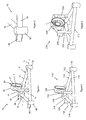
- FIG. 1 of the accompanying drawings there is illustrated a first embodiment of a hydroelectric turbine system according to the present invention, generally indicated as 10, which is designed to be located on the seabed in an area of high tidal flow, in order to effect the hydroelectric generation of electricity.
- the system 10 comprises a base 12 which is adapted to carry a hydroelectric turbine T thereon, which turbine T may then form part of the system 10.
- the base 12 is triangular in plan, although it will be appreciated from the following description of the operation of the system 10 that the shape of the base 12 is not limited to being triangular, and may be of any other suitable form.
- the hydroelectric turbine T to be mounted on the base 12 may be of any suitable form.
- the base 12 comprises a pair of lateral beams 14 extending between which is a rear beam 16, each apex of the base 12 being defined by a foot 18, between which the beams 14, 16 extend.
- the feet 18 may be suitably designed to be fixed to the seabed in any number of arrangements.
- the base 12 may be made of any suitable material or combination of materials, and in the embodiment illustrated is formed primarily of tubular steel.
- the base 12 may be modular in nature in order to allow repair and/or replacement of individual components thereof.
- the system 10 further comprises a mount 20 secured to the base 12, and which is adapted to receive and retain the hydroelectric turbine T therein.
- the mount includes a pair of uprights 22, each of which extends from a respective one of the lateral beams 14, and a split collar 24 supported on the uprights 22.
- the collar 24 is substantially cylindrical in shape, and in use receives the hydroelectric turbine therein, which may be secured to the collar 24 via a stator (not shown) of the turbine.
- the design of the mount 20 is merely one example of a mechanism for securing a turbine to the base 12, and the mount 20 may be of any other suitable form.
- the system 10 is designed such that when mounted on the seabed, a longitudinal axis L of the base 12 should be substantially aligned with the direction of tidal flow at the deployment site.
- the mount 20 is therefore oriented in order to face the hydroelectric turbine directly into the direction of tidal flow, with the base 12 located on the seabed.
- the system 10 is intended to be lowered to the seabed from a barge or similar deployment vessel (not shown), for example using a number of lowering lines connected to the base 12 and lowered via winches from the deployment vessel.
- the areas in which the system 10 will be deployed will be areas of high tidal flow, which embody difficult working conditions both on and below the surface of the sea. Lowering an object from a vessel towards the seabed in such high tidal flows is extremely difficult, and will generally result in undesired movement such as spinning/oscillation of the object.
- the system 10 of the present invention overcomes the above-mentioned problems by providing aligning means in the form of a pair of fins 26 mounted to the base 12, and in particular extending rearwardly from the feet 18 mounted on either of the rear beam 16.
- the fins 26 are substantially aligned with the longitudinal axis L of the base 12. Once lowered into the tidal flow, the fins 26 act as rudders providing stability to the base 12 and also effecting alignment of the base 12 with respect to the tidal flow, forcing rotation of the base 12 until the longitudinal axis L is substantially parallel with the direction of tidal flow.
- the orientation of the fins 26 may be varied in order to achieve a desired orientation of the base 12 with respect to the direction of tidal flow.
- the system 10 is intended to be lowered to the seabed from the deployment vessel with the rear beam 16 defining a trailing edge of the system 10.
- the fins 26 could of course be positioned at any other location, or supplemented with additional fins (not shown) located around the base 12.
- the system 10 of the present invention therefore utilises the kinetic energy of the tidal flow in order to both stabilise and correctly orient the system 10 as it is lowered from a deployment vessel towards the seabed.
- the aligning means in the form of the pair of fins 26, may therefore be passive as they utilise this kinetic energy of the tidal flow as a source of power to provide the above mentioned functionality.
- active aligning means could be utilised, for example in the form of one or more propellers, water jets, etc., in order to effect the stabilisation and orientation of the system 10 when being lowered in a tidal flow.
- the passive fins 26 are a simple yet highly effective aligning means for the system 10.
- FIG. 2 the rear corner of the base 12 is shown, in which the fin 26 is shown mounted in a slightly different position, whereby a gap is left between the upper edge of the fin 26 and the top of the foot 18. This is to prevent the fin 26 from piercing or otherwise damaging the barge or similar deployment vessel (not shown), used to deploy the system 10.
- the system 10 is intended to be towed to a particular deployment site suspended beneath the deployment vessel, and to be then lowered away from the underside of the deployment vessel towards the seabed.
- the system 10 may be lowered unevenly from beneath the barge, which could result in one or more of the fins 26 contacting the underside of the barge.
- FIG. 3 there is illustrated a second embodiment of a hydroelectric turbine system according to the present invention, generally indicated as 110.
- the system 110 comprises a base 112 which is formed from a pair of lateral beams 114 connected between which is a rear beam 116. Each apex of the base 112 is defined by a foot 118.
- the system 110 would be provided with a mount for securing a hydroelectric turbine T to the base 112 to form part of the system 110.
- the system 110 further comprises aligning means in the form of a pair of fins 126 which are mounted on the rear beam 116, and which project upwardly and rearwardly from the rear beam 116.
- aligning means in the form of a pair of fins 126 which are mounted on the rear beam 116, and which project upwardly and rearwardly from the rear beam 116.
- FIG. 4 there is illustrated a third embodiment of a hydroelectric turbine system, generally indicated as 210.
- like components have again been accorded like reference numerals, and unless otherwise stated perform a like function.
- Figure 4 shows only a portion of the alternative embodiment, and in particular shows a mount 220 to which a hydroelectric turbine T is secured, similar to the arrangement of the first embodiment described above.
- the mount 220 comprises a pair of uprights 222 and collar 224 into which the turbine T is seated.
- the system 210 further comprises aligning means in the form of a pair of fins 226 which project from the pair of uprights 222. Again the tidal flow of water past this position of the system 210 may be less turbulent than the flow past and around the base 212 of the system 210.
- the aligning means may be located at any other suitable location, and may be of any other suitable form, once capable of stabilising and/or orienting the system when suspended, or being lowered/raised, in a tidal flow.
- the system 10, 110, 210 of the present invention greatly simplifies the deployment of a hydroelectric turbine onto the seabed. This is achieved by stabilising the system as it is lowered towards the seabed and conversely when the system is being raised from the seabed, for example, for repair or replacement.
- the system and method of the invention avoid tangling of lowering lines, and ensure that the system is correctly oriented when it reaches the seabed, thereby avoiding the need for further positioning at that stage.
- the system and method of the invention are designed to allow deployment during a running tide, as opposed to during slack water, the time allowed for a deployment or recovery of the system is greatly increased.
Landscapes
- Engineering & Computer Science (AREA)
- General Engineering & Computer Science (AREA)
- Mechanical Engineering (AREA)
- Chemical & Material Sciences (AREA)
- Combustion & Propulsion (AREA)
- Power Engineering (AREA)
- Life Sciences & Earth Sciences (AREA)
- General Life Sciences & Earth Sciences (AREA)
- Oceanography (AREA)
- Civil Engineering (AREA)
- Structural Engineering (AREA)
- Other Liquid Machine Or Engine Such As Wave Power Use (AREA)
Description
- The present invention relates to a hydroelectric turbine system, in particular a system comprising a hydroelectric turbine mounted on a base, the system including means to stabilising and/or orient the system while being lowered, during a running tide, towards a deployment site on the seabed.
- Currently, and at a global scale, there is great concern surrounding the damage that the emission of CO2 is causing to our environment, in particular the threat posed by global warming. One of the major sources of CO2 emission is in the production of electricity, on a large scale, through the burning of fossil fuels. Electricity is however a commodity that has become essential to the survival of the human race, and there are thus vast resources currently being expended in seeking alternative means of generating large quantities of electricity without the use of fossil fuel. While nuclear energy is one such alternative, most societies are uncomfortable with the negative aspects of nuclear power and thus other more desirable solutions are required.
- Renewable energy has thus come to the fore in recent years, with many projects being developed around solar energy, wind energy, and tidal power. Of these alternative forms of energy, tidal power is arguably the most attractive, given that tidal flows are entirely predictable and constant, unlike wind or solar energy which are relatively intermittent and therefore less dependable.
- However, harnessing tidal energy does provide its own challenges, in particular with respect to the installation and maintenance of tidal power generators, for example hydroelectric turbines, which by the very nature of the operation of same must be located in relatively fast flowing tidal currents, and more than likely located on the seabed. These conditions are significantly inhospitable, and are not conducive to safe working conditions. The installation of a base on which such tidal turbines are mounted has conventionally taken the form of the sinking of a pile into the seabed, on which pile a turbine or secondary frame carrying one or more turbines can then be located. However, the sinking of a pile into the seabed in an area of high tidal flow is considerably problematic and generally a dangerous operation. In addition, significant drilling and piling equipment must be transported to and operated at the site of installation, significantly increasing the complexity and cost of the operation.
-
EP 1980746 A1 discloses a method of installing a hydroelectric turbine, where the orientation in the tidal flow is achieved by a tub or an anchor. - According to the present invention there is provided a method of deploying, in a running tide, a hydroelectric turbine system, the method comprising the steps as claimed in the claim 1, the steps being
positioning a deployment vessel and the system above a deployment site;
lowering the system from the vessel towards the deployment site;
utilising the tidal flow of water past the system to achieve and/or maintain a desired orientation of the system with respect to the tidal flow. - Preferably, the method comprises utilising the tidal flow of water past the system to effect and/or maintain stability of the system in the tidal flow.
- Preferably, the method comprises, in the step of lowering the system, utilising lowering means which permit the system to be displaced into a desired orientation, relative to the direction of the tidal flow, under the influence of the flow of water moving past the system.
- Preferably, the method comprises allowing the tidal flow to flow past aligning means on the system such as to effect displacement of the system in order to stabilise and/or orient the system with respect to the tidal flow.
- Preferably, the system comprises a base and a hydroelectric turbine mountable on the base, the method comprising the step of securing the turbine to the base prior to lowering the system towards the seabed.
- Preferably, the method comprises utilising the tidal flow to orient the system such that the turbine is operatively aligned with the direction of the tidal flow.
-
-
Figure 1 illustrates a perspective view of a first embodiment of a hydroelectric turbine system according to the present invention; -
Figure 2 illustrates an alternative arrangement of a portion of the hydroelectric turbine system shown inFigure 1 ; -
Figure 3 illustrates a perspective view of a second embodiment of a hydroelectric turbine system according to the present invention; and -
Figure 4 illustrates a perspective view of a portion of a hydroelectric turbine system according to a third embodiment of the invention. - Referring now to
Figure 1 of the accompanying drawings, there is illustrated a first embodiment of a hydroelectric turbine system according to the present invention, generally indicated as 10, which is designed to be located on the seabed in an area of high tidal flow, in order to effect the hydroelectric generation of electricity. Thesystem 10 comprises abase 12 which is adapted to carry a hydroelectric turbine T thereon, which turbine T may then form part of thesystem 10. In the embodiment illustrated thebase 12 is triangular in plan, although it will be appreciated from the following description of the operation of thesystem 10 that the shape of thebase 12 is not limited to being triangular, and may be of any other suitable form. It will also be appreciated that the hydroelectric turbine T to be mounted on thebase 12 may be of any suitable form. - The
base 12 comprises a pair oflateral beams 14 extending between which is arear beam 16, each apex of thebase 12 being defined by afoot 18, between which thebeams feet 18 may be suitably designed to be fixed to the seabed in any number of arrangements. Thebase 12 may be made of any suitable material or combination of materials, and in the embodiment illustrated is formed primarily of tubular steel. Thebase 12 may be modular in nature in order to allow repair and/or replacement of individual components thereof. - The
system 10 further comprises amount 20 secured to thebase 12, and which is adapted to receive and retain the hydroelectric turbine T therein. The mount includes a pair ofuprights 22, each of which extends from a respective one of thelateral beams 14, and asplit collar 24 supported on theuprights 22. Thecollar 24 is substantially cylindrical in shape, and in use receives the hydroelectric turbine therein, which may be secured to thecollar 24 via a stator (not shown) of the turbine. Again it will be appreciated that the design of themount 20 is merely one example of a mechanism for securing a turbine to thebase 12, and themount 20 may be of any other suitable form. In the embodiment illustrated thesystem 10 is designed such that when mounted on the seabed, a longitudinal axis L of thebase 12 should be substantially aligned with the direction of tidal flow at the deployment site. Themount 20 is therefore oriented in order to face the hydroelectric turbine directly into the direction of tidal flow, with thebase 12 located on the seabed. - The
system 10 is intended to be lowered to the seabed from a barge or similar deployment vessel (not shown), for example using a number of lowering lines connected to thebase 12 and lowered via winches from the deployment vessel. As mentioned above, the areas in which thesystem 10 will be deployed will be areas of high tidal flow, which embody difficult working conditions both on and below the surface of the sea. Lowering an object from a vessel towards the seabed in such high tidal flows is extremely difficult, and will generally result in undesired movement such as spinning/oscillation of the object. This can result in tangling of the lines being used to lower the object, and, in the case of a hydroelectric turbine, which must be accurately aligned with the tidal flow, can make it extremely difficult to correctly orient the turbine with respect to the direction of tidal flow, when positioning the turbine onto the seabed. - The
system 10 of the present invention overcomes the above-mentioned problems by providing aligning means in the form of a pair offins 26 mounted to thebase 12, and in particular extending rearwardly from thefeet 18 mounted on either of therear beam 16. In the embodiment illustrated thefins 26 are substantially aligned with the longitudinal axis L of thebase 12. Once lowered into the tidal flow, thefins 26 act as rudders providing stability to thebase 12 and also effecting alignment of thebase 12 with respect to the tidal flow, forcing rotation of thebase 12 until the longitudinal axis L is substantially parallel with the direction of tidal flow. It will of course be understood that the orientation of thefins 26 may be varied in order to achieve a desired orientation of thebase 12 with respect to the direction of tidal flow. - In the embodiment illustrated the
system 10 is intended to be lowered to the seabed from the deployment vessel with therear beam 16 defining a trailing edge of thesystem 10. This means that the forward tip of the triangular plan of thebase 12 points into the tidal flow, with the pair offins 26 trailing from the rear. In this position the pair offins 26 are at their most effective, both in terms of stabilising and orienting thesystem 10 in the tidal flow. Thefins 26 could of course be positioned at any other location, or supplemented with additional fins (not shown) located around thebase 12. - The
system 10 of the present invention therefore utilises the kinetic energy of the tidal flow in order to both stabilise and correctly orient thesystem 10 as it is lowered from a deployment vessel towards the seabed. The aligning means, in the form of the pair offins 26, may therefore be passive as they utilise this kinetic energy of the tidal flow as a source of power to provide the above mentioned functionality. It will be appreciated that active aligning means (not shown) could be utilised, for example in the form of one or more propellers, water jets, etc., in order to effect the stabilisation and orientation of thesystem 10 when being lowered in a tidal flow. However, this would add to both the cost and complexity of thesystem 10, and given the harsh underwater conditions in which thesystem 10 will reside for extended periods, the reliability of such active aligning means could be an issue. Thepassive fins 26 are a simple yet highly effective aligning means for thesystem 10. - Turning now to
Figure 2 , the rear corner of thebase 12 is shown, in which thefin 26 is shown mounted in a slightly different position, whereby a gap is left between the upper edge of thefin 26 and the top of thefoot 18. This is to prevent thefin 26 from piercing or otherwise damaging the barge or similar deployment vessel (not shown), used to deploy thesystem 10. Thesystem 10 is intended to be towed to a particular deployment site suspended beneath the deployment vessel, and to be then lowered away from the underside of the deployment vessel towards the seabed. Thus, in particular given the relatively harsh conditions present at these deployment sites, it is possible that thesystem 10 may be lowered unevenly from beneath the barge, which could result in one or more of thefins 26 contacting the underside of the barge. By lowering thefins 26 slightly beneath the upper edge of thefeet 18, such an occurrence is rendered extremely unlikely. - Referring now to
Figure 3 , there is illustrated a second embodiment of a hydroelectric turbine system according to the present invention, generally indicated as 110. In this second embodiment like components have been accorded like reference numerals, and unless otherwise stated perform a like function. Thesystem 110 comprises a base 112 which is formed from a pair oflateral beams 114 connected between which is arear beam 116. Each apex of thebase 112 is defined by afoot 118. Although not illustrated, in use thesystem 110 would be provided with a mount for securing a hydroelectric turbine T to the base 112 to form part of thesystem 110. - The
system 110 further comprises aligning means in the form of a pair offins 126 which are mounted on therear beam 116, and which project upwardly and rearwardly from therear beam 116. In use the tidal flow of water past thefins 126 will be cleaner or less turbulent than the flow past thefins 26 as positioned on thesystem 10 of the first embodiment. As a result thefins 126 of the second embodiment will be more effective in stabilising and orienting thesystem 110 with respect to the direction of tidal flow. - Referring to
Figure 4 , there is illustrated a third embodiment of a hydroelectric turbine system, generally indicated as 210. In this third embodiment like components have again been accorded like reference numerals, and unless otherwise stated perform a like function.Figure 4 shows only a portion of the alternative embodiment, and in particular shows a mount 220 to which a hydroelectric turbine T is secured, similar to the arrangement of the first embodiment described above. - The mount 220 comprises a pair of
uprights 222 andcollar 224 into which the turbine T is seated. Thesystem 210 further comprises aligning means in the form of a pair offins 226 which project from the pair ofuprights 222. Again the tidal flow of water past this position of thesystem 210 may be less turbulent than the flow past and around thebase 212 of thesystem 210. - It will of course be appreciated that the invention may be implemented by utilising a combination of the above mentioned positions for the aligning means. The aligning means may be located at any other suitable location, and may be of any other suitable form, once capable of stabilising and/or orienting the system when suspended, or being lowered/raised, in a tidal flow.
- It will thus be appreciated that the
system
Claims (5)
- A method of deploying, in a running tide, a hydroelectric turbine system(10), the method comprising the steps of;
positioning a deployment vessel and the system above a deployment site;
lowering the system from the vessel towards the deployment site;
utilising the tidal flow of water past the system to achieve and/or maintain a desired orientation of the system with respect to the tidal flow
characterised by allowing the tidal flow to flow past aligning means in the form of a pair of fins(26) mounted to a base(12) of the system such as to effect displacement of the system in order to orient and/or stabilize the system with respect to the tidal flow. - A method according to claim 1 comprising utilising the tidal flow of water past the system to effect and/or maintain stability of the system in the tidal flow.
- A method according to claim 1 or 2 comprising, in the step of lowering the system, utilising lowering means which permit the system to be displaced into a desired orientation, relative to the direction of the tidal flow, under the influence of the flow of water moving past the system.
- A method according to any of claims 1 to 3 in which the system comprises a hydroelectric turbine (T) mountable on the base, the method comprising the step of securing the turbine to the base prior to lowering the system towards the seabed.
- A method according to claim 4 comprising utilising the tidal flow to orient the system such that the turbine is operatively aligned with the direction of the tidal flow.
Priority Applications (11)
| Application Number | Priority Date | Filing Date | Title |
|---|---|---|---|
| EP08021993.4A EP2199601B1 (en) | 2008-12-18 | 2008-12-18 | A method of deployment of hydroelectric turbine with aligning means |
| MYPI2011002818A MY163960A (en) | 2008-12-18 | 2009-12-14 | A method of deployment of hydroelectric turbine with aligning means |
| CA2746715A CA2746715C (en) | 2008-12-18 | 2009-12-14 | A hydroelectric turbine system with aligning means |
| JP2011541187A JP5588997B2 (en) | 2008-12-18 | 2009-12-14 | Hydroelectric turbine system with direction adjustment means |
| PCT/EP2009/008944 WO2010069539A1 (en) | 2008-12-18 | 2009-12-14 | A hydroelectric turbine with aligning means and method of deployment |
| NZ593256A NZ593256A (en) | 2008-12-18 | 2009-12-14 | A hydroelectric turbine with aligning means and method of deployment |
| KR1020117016318A KR101697679B1 (en) | 2008-12-18 | 2009-12-14 | A hydroelectric turbine with aligning means and method of deployment |
| SG2011040953A SG171971A1 (en) | 2008-12-18 | 2009-12-14 | A hydroelectric turbine with aligning means and method of deployment |
| AU2009328529A AU2009328529B2 (en) | 2008-12-18 | 2009-12-14 | A hydroelectric turbine with aligning means and method of deployment |
| CN200980150942.5A CN102257267B (en) | 2008-12-18 | 2009-12-14 | A hydroelectric turbine with aligning means and method of deployment |
| US13/133,235 US20110291419A1 (en) | 2008-12-18 | 2009-12-14 | hydroelectric turbine with aligning means |
Applications Claiming Priority (1)
| Application Number | Priority Date | Filing Date | Title |
|---|---|---|---|
| EP08021993.4A EP2199601B1 (en) | 2008-12-18 | 2008-12-18 | A method of deployment of hydroelectric turbine with aligning means |
Publications (2)
| Publication Number | Publication Date |
|---|---|
| EP2199601A1 EP2199601A1 (en) | 2010-06-23 |
| EP2199601B1 true EP2199601B1 (en) | 2013-11-06 |
Family
ID=40848386
Family Applications (1)
| Application Number | Title | Priority Date | Filing Date |
|---|---|---|---|
| EP08021993.4A Not-in-force EP2199601B1 (en) | 2008-12-18 | 2008-12-18 | A method of deployment of hydroelectric turbine with aligning means |
Country Status (11)
| Country | Link |
|---|---|
| US (1) | US20110291419A1 (en) |
| EP (1) | EP2199601B1 (en) |
| JP (1) | JP5588997B2 (en) |
| KR (1) | KR101697679B1 (en) |
| CN (1) | CN102257267B (en) |
| AU (1) | AU2009328529B2 (en) |
| CA (1) | CA2746715C (en) |
| MY (1) | MY163960A (en) |
| NZ (1) | NZ593256A (en) |
| SG (1) | SG171971A1 (en) |
| WO (1) | WO2010069539A1 (en) |
Cited By (12)
| Publication number | Priority date | Publication date | Assignee | Title |
|---|---|---|---|---|
| US8596964B2 (en) | 2006-07-14 | 2013-12-03 | Openhydro Group Limited | Turbines having a debris release chute |
| US8690526B2 (en) | 2008-12-18 | 2014-04-08 | Openhydro Ip Limited | Hydroelectric turbine with passive braking |
| US8754540B2 (en) | 2008-02-05 | 2014-06-17 | James Ives | Hydroelectric turbine with floating rotor |
| US8784005B2 (en) | 2008-04-17 | 2014-07-22 | Openhydro Group Limited | Turbine installation method |
| US8864439B2 (en) | 2006-07-14 | 2014-10-21 | Openhydro Ip Limited | Tidal flow hydroelectric turbine |
| US8872371B2 (en) | 2009-04-17 | 2014-10-28 | OpenHydro IP Liminted | Enhanced method of controlling the output of a hydroelectric turbine generator |
| US8933598B2 (en) | 2009-09-29 | 2015-01-13 | Openhydro Ip Limited | Hydroelectric turbine with coil cooling |
| US9054512B2 (en) | 2008-12-19 | 2015-06-09 | Openhydro Ip Limited | Method of installing a hydroelectric turbine generator |
| US9236725B2 (en) | 2009-09-29 | 2016-01-12 | Openhydro Ip Limited | Hydroelectric turbine cabling system |
| US9234492B2 (en) | 2010-12-23 | 2016-01-12 | Openhydro Ip Limited | Hydroelectric turbine testing method |
| US9284709B2 (en) | 2007-04-11 | 2016-03-15 | Openhydro Group Limited | Method of installing a hydroelectric turbine |
| US9473046B2 (en) | 2009-09-29 | 2016-10-18 | Openhydro Ip Limited | Electrical power conversion system and method |
Families Citing this family (17)
| Publication number | Priority date | Publication date | Assignee | Title |
|---|---|---|---|---|
| ATE538304T1 (en) | 2006-07-14 | 2012-01-15 | Openhydro Group Ltd | UNDERWATER HYDROELECTRIC TURBINES WITH FLOATS |
| EP1879280B1 (en) | 2006-07-14 | 2014-03-05 | OpenHydro Group Limited | A hydroelectric turbine |
| EP2450562B1 (en) | 2010-11-09 | 2015-06-24 | Openhydro IP Limited | A hydroelectric turbine recovery system and a method therefore |
| GB201105620D0 (en) * | 2011-04-04 | 2011-05-18 | Qed Naval Ltd | Submersible apparatus and methods of installing anchoring equipment |
| EP2607682B1 (en) * | 2011-12-21 | 2017-08-16 | Openhydro IP Limited | A hydroelectric turbine system |
| CN102536599B (en) * | 2011-12-31 | 2015-03-18 | 李殿海 | Underwater turbine generator |
| AU2012213967B2 (en) * | 2012-04-24 | 2014-11-06 | Anadarko Petroleum Corporation | Subsystems for a water current power generation system |
| CN102678437B (en) * | 2012-05-25 | 2014-12-17 | 施安如 | Tidal current generation device |
| CN102777314B (en) * | 2012-06-26 | 2015-04-22 | 浙江大学宁波理工学院 | Tidal stream energy axial flow power generating device |
| EP2719833B1 (en) * | 2012-10-15 | 2015-08-05 | Openhydro IP Limited | A Hydroelectric Turbine System |
| KR101874213B1 (en) * | 2013-06-12 | 2018-07-03 | 디퍼렌셜 다이나믹스 코포레이션 | Run-of-the-river or ocean current turbine |
| CA2950002C (en) * | 2014-05-30 | 2020-05-26 | Oceana Energy Company | Hydroelectric turbines, anchoring structures, and related methods of assembly |
| EP3037654A1 (en) * | 2014-12-23 | 2016-06-29 | Openhydro IP Limited | Adaptive hydroelectric turbine system |
| US10544775B2 (en) | 2015-10-22 | 2020-01-28 | Oceana Energy Company | Hydroelectric energy systems, and related components and methods |
| US11105367B2 (en) | 2019-01-18 | 2021-08-31 | Telesystem Energy Ltd. | Passive magnetic bearing and rotating machineries integrating said bearing, including energy production turbines |
| KR20210138680A (en) | 2019-03-14 | 2021-11-19 | 텔레시스템 에너지 리미티드 | Multi-stage cowl for hydrodynamic turbines |
| US12085053B2 (en) | 2021-06-22 | 2024-09-10 | Riahmedia Inc. | Systems and methods for power distribution and harnessing of marine hydrokinetic energy |
Family Cites Families (16)
| Publication number | Priority date | Publication date | Assignee | Title |
|---|---|---|---|---|
| GB204505A (en) * | 1922-09-07 | 1923-10-04 | Thomas Mccormac Adair | Improvements in connection with turbines for utilizing tides or currents for producing electricity and for other purposes |
| JPS6355370A (en) * | 1986-08-22 | 1988-03-09 | Akaho Yoshio | Tidal power generating device using daryavaus type turbine |
| US6626638B2 (en) * | 1999-07-29 | 2003-09-30 | Jonathan B. Rosefsky | Ribbon drive power generation for variable flow conditions |
| US20020088222A1 (en) * | 2000-04-06 | 2002-07-11 | Philippe Vauthier | Dual hydroturbine unit with counter-rotating turbines |
| AU2000251235A1 (en) * | 2000-05-26 | 2001-01-02 | Philippe Vauthier | Dual hydroturbine unit |
| US6756695B2 (en) * | 2001-08-09 | 2004-06-29 | Aerovironment Inc. | Method of and apparatus for wave energy conversion using a float with excess buoyancy |
| ITMI20012505A1 (en) * | 2001-11-29 | 2003-05-29 | Roberto Pizzigalli | HYDRODYNAMIC EQUIPMENT FOR THE GENERATION OF ELECTRIC CURRENT |
| GB0220626D0 (en) * | 2002-09-05 | 2002-10-16 | Univ Robert Gordon | Apparatus for controlling the launch, secure positioning and/or recovery of marine based equipment situated in sea or river currents |
| US7234409B2 (en) * | 2003-04-04 | 2007-06-26 | Logima V/Svend Erik Hansen | Vessel for transporting wind turbines, methods of moving a wind turbine, and a wind turbine for an off-shore wind farm |
| US7223137B1 (en) * | 2005-07-15 | 2007-05-29 | Sosnowski Michael J | Floating, water current-driven electrical power generation system |
| CA2544108C (en) * | 2006-04-19 | 2013-06-04 | Metin Ilbay Yaras | Vortex hydraulic turbine |
| GB0704897D0 (en) * | 2007-03-14 | 2007-04-18 | Rotech Holdings Ltd | Power generator and turbine unit |
| EP1980670B1 (en) * | 2007-04-11 | 2009-07-15 | OpenHydro Group Limited | Method for the deployment of a hydroelectric turbine |
| DE602007007294D1 (en) * | 2007-04-11 | 2010-08-05 | Openhydro Group Ltd | Method for installing hydroelectric turbines |
| US8148839B2 (en) * | 2008-07-02 | 2012-04-03 | Rosefsky Jonathan B | Ribbon drive power generation and method of use |
| EP2199602A1 (en) * | 2008-12-18 | 2010-06-23 | OpenHydro IP Limited | A method of securing a hydroelectric turbine at a deployment site and hydroelectric turbine |
-
2008
- 2008-12-18 EP EP08021993.4A patent/EP2199601B1/en not_active Not-in-force
-
2009
- 2009-12-14 MY MYPI2011002818A patent/MY163960A/en unknown
- 2009-12-14 KR KR1020117016318A patent/KR101697679B1/en active IP Right Grant
- 2009-12-14 US US13/133,235 patent/US20110291419A1/en not_active Abandoned
- 2009-12-14 JP JP2011541187A patent/JP5588997B2/en not_active Expired - Fee Related
- 2009-12-14 AU AU2009328529A patent/AU2009328529B2/en not_active Ceased
- 2009-12-14 NZ NZ593256A patent/NZ593256A/en unknown
- 2009-12-14 CN CN200980150942.5A patent/CN102257267B/en not_active Expired - Fee Related
- 2009-12-14 SG SG2011040953A patent/SG171971A1/en unknown
- 2009-12-14 CA CA2746715A patent/CA2746715C/en not_active Expired - Fee Related
- 2009-12-14 WO PCT/EP2009/008944 patent/WO2010069539A1/en active Application Filing
Cited By (12)
| Publication number | Priority date | Publication date | Assignee | Title |
|---|---|---|---|---|
| US8596964B2 (en) | 2006-07-14 | 2013-12-03 | Openhydro Group Limited | Turbines having a debris release chute |
| US8864439B2 (en) | 2006-07-14 | 2014-10-21 | Openhydro Ip Limited | Tidal flow hydroelectric turbine |
| US9284709B2 (en) | 2007-04-11 | 2016-03-15 | Openhydro Group Limited | Method of installing a hydroelectric turbine |
| US8754540B2 (en) | 2008-02-05 | 2014-06-17 | James Ives | Hydroelectric turbine with floating rotor |
| US8784005B2 (en) | 2008-04-17 | 2014-07-22 | Openhydro Group Limited | Turbine installation method |
| US8690526B2 (en) | 2008-12-18 | 2014-04-08 | Openhydro Ip Limited | Hydroelectric turbine with passive braking |
| US9054512B2 (en) | 2008-12-19 | 2015-06-09 | Openhydro Ip Limited | Method of installing a hydroelectric turbine generator |
| US8872371B2 (en) | 2009-04-17 | 2014-10-28 | OpenHydro IP Liminted | Enhanced method of controlling the output of a hydroelectric turbine generator |
| US8933598B2 (en) | 2009-09-29 | 2015-01-13 | Openhydro Ip Limited | Hydroelectric turbine with coil cooling |
| US9236725B2 (en) | 2009-09-29 | 2016-01-12 | Openhydro Ip Limited | Hydroelectric turbine cabling system |
| US9473046B2 (en) | 2009-09-29 | 2016-10-18 | Openhydro Ip Limited | Electrical power conversion system and method |
| US9234492B2 (en) | 2010-12-23 | 2016-01-12 | Openhydro Ip Limited | Hydroelectric turbine testing method |
Also Published As
| Publication number | Publication date |
|---|---|
| EP2199601A1 (en) | 2010-06-23 |
| KR101697679B1 (en) | 2017-01-18 |
| WO2010069539A1 (en) | 2010-06-24 |
| AU2009328529B2 (en) | 2015-09-17 |
| CN102257267A (en) | 2011-11-23 |
| JP2012512355A (en) | 2012-05-31 |
| MY163960A (en) | 2017-11-15 |
| CN102257267B (en) | 2015-05-13 |
| CA2746715C (en) | 2017-04-25 |
| JP5588997B2 (en) | 2014-09-10 |
| SG171971A1 (en) | 2011-07-28 |
| CA2746715A1 (en) | 2010-06-24 |
| NZ593256A (en) | 2013-11-29 |
| US20110291419A1 (en) | 2011-12-01 |
| KR20110113613A (en) | 2011-10-17 |
| AU2009328529A1 (en) | 2011-07-07 |
Similar Documents
| Publication | Publication Date | Title |
|---|---|---|
| EP2199601B1 (en) | A method of deployment of hydroelectric turbine with aligning means | |
| EP1980746B2 (en) | A method of installing a hydroelectric turbine | |
| JP2012512353A (en) | Fixing the hydropower turbine to the location | |
| EP1980670B1 (en) | Method for the deployment of a hydroelectric turbine | |
| US8237304B2 (en) | Multi-point tethering and stability system and control method for underwater current turbine | |
| EP2122160B1 (en) | Underwater power generator | |
| KR101697676B1 (en) | A hydroelectric turbine support system and method | |
| KR20110004389A (en) | An improved turbine installation method | |
| US20170342957A1 (en) | Support structure for tidal energy converter system | |
| US20240209825A1 (en) | Cycloturbine modular river current energy converter and method and apparatus for deploying marine hydrokinetic turbine assembly to harvest riverine and ocean tidal current energy | |
| EP3339630A1 (en) | A method and system of deploying or recovering a hydroelectric turbine | |
| Khodabux et al. | A review of offshore wind turbines and their various classifications | |
| EP2886851A1 (en) | An improved hyrdoelectric turbine system | |
| Coiro et al. | Design, towing tank test and deployment of full scale GEM, a novel tethered system for harnessing tidal energy | |
| Coiro | Development of innovative tidal current energy converters: from research to deployment | |
| NO332202B1 (en) | System for installing a nacelle for an axial turbine on a submerged foundation, a nacelle, and a saddle for installing the nacelle | |
| KR20030024225A (en) | Current Power Generation System | |
| JP2016217151A (en) | Power generation system and control method of power generation system | |
| JP2015135066A (en) | Floating body type wind turbine generator system | |
| Jo et al. | Experimental study on tensioned wire maintenance concept for tidal current turbine | |
| GB2546562A (en) | Underwater power generation system |
Legal Events
| Date | Code | Title | Description |
|---|---|---|---|
| PUAI | Public reference made under article 153(3) epc to a published international application that has entered the european phase |
Free format text: ORIGINAL CODE: 0009012 |
|
| AK | Designated contracting states |
Kind code of ref document: A1 Designated state(s): AT BE BG CH CY CZ DE DK EE ES FI FR GB GR HR HU IE IS IT LI LT LU LV MC MT NL NO PL PT RO SE SI SK TR |
|
| AX | Request for extension of the european patent |
Extension state: AL BA MK RS |
|
| 17P | Request for examination filed |
Effective date: 20101221 |
|
| AKX | Designation fees paid |
Designated state(s): AT BE BG CH CY CZ DE DK EE ES FI FR GB GR HR HU IE IS IT LI LT LU LV MC MT NL NO PL PT RO SE SI SK TR |
|
| 17Q | First examination report despatched |
Effective date: 20110217 |
|
| REG | Reference to a national code |
Ref country code: DE Ref legal event code: R079 Ref document number: 602008028492 Country of ref document: DE Free format text: PREVIOUS MAIN CLASS: F03B0013260000 Ipc: E02B0009080000 |
|
| RIC1 | Information provided on ipc code assigned before grant |
Ipc: F03B 17/06 20060101ALI20130312BHEP Ipc: E02B 9/08 20060101AFI20130312BHEP Ipc: F03B 13/26 20060101ALI20130312BHEP |
|
| GRAP | Despatch of communication of intention to grant a patent |
Free format text: ORIGINAL CODE: EPIDOSNIGR1 |
|
| INTG | Intention to grant announced |
Effective date: 20130515 |
|
| GRAS | Grant fee paid |
Free format text: ORIGINAL CODE: EPIDOSNIGR3 |
|
| GRAA | (expected) grant |
Free format text: ORIGINAL CODE: 0009210 |
|
| AK | Designated contracting states |
Kind code of ref document: B1 Designated state(s): AT BE BG CH CY CZ DE DK EE ES FI FR GB GR HR HU IE IS IT LI LT LU LV MC MT NL NO PL PT RO SE SI SK TR |
|
| REG | Reference to a national code |
Ref country code: GB Ref legal event code: FG4D |
|
| REG | Reference to a national code |
Ref country code: CH Ref legal event code: EP |
|
| REG | Reference to a national code |
Ref country code: AT Ref legal event code: REF Ref document number: 639601 Country of ref document: AT Kind code of ref document: T Effective date: 20131215 |
|
| REG | Reference to a national code |
Ref country code: IE Ref legal event code: FG4D |
|
| REG | Reference to a national code |
Ref country code: DE Ref legal event code: R096 Ref document number: 602008028492 Country of ref document: DE Effective date: 20140102 |
|
| REG | Reference to a national code |
Ref country code: NL Ref legal event code: VDEP Effective date: 20131106 |
|
| REG | Reference to a national code |
Ref country code: AT Ref legal event code: MK05 Ref document number: 639601 Country of ref document: AT Kind code of ref document: T Effective date: 20131106 |
|
| REG | Reference to a national code |
Ref country code: NO Ref legal event code: T2 Effective date: 20131106 |
|
| REG | Reference to a national code |
Ref country code: LT Ref legal event code: MG4D |
|
| PG25 | Lapsed in a contracting state [announced via postgrant information from national office to epo] |
Ref country code: FI Free format text: LAPSE BECAUSE OF FAILURE TO SUBMIT A TRANSLATION OF THE DESCRIPTION OR TO PAY THE FEE WITHIN THE PRESCRIBED TIME-LIMIT Effective date: 20131106 Ref country code: SE Free format text: LAPSE BECAUSE OF FAILURE TO SUBMIT A TRANSLATION OF THE DESCRIPTION OR TO PAY THE FEE WITHIN THE PRESCRIBED TIME-LIMIT Effective date: 20131106 Ref country code: HR Free format text: LAPSE BECAUSE OF FAILURE TO SUBMIT A TRANSLATION OF THE DESCRIPTION OR TO PAY THE FEE WITHIN THE PRESCRIBED TIME-LIMIT Effective date: 20131106 Ref country code: NL Free format text: LAPSE BECAUSE OF FAILURE TO SUBMIT A TRANSLATION OF THE DESCRIPTION OR TO PAY THE FEE WITHIN THE PRESCRIBED TIME-LIMIT Effective date: 20131106 Ref country code: LT Free format text: LAPSE BECAUSE OF FAILURE TO SUBMIT A TRANSLATION OF THE DESCRIPTION OR TO PAY THE FEE WITHIN THE PRESCRIBED TIME-LIMIT Effective date: 20131106 Ref country code: IS Free format text: LAPSE BECAUSE OF FAILURE TO SUBMIT A TRANSLATION OF THE DESCRIPTION OR TO PAY THE FEE WITHIN THE PRESCRIBED TIME-LIMIT Effective date: 20140306 |
|
| PG25 | Lapsed in a contracting state [announced via postgrant information from national office to epo] |
Ref country code: AT Free format text: LAPSE BECAUSE OF FAILURE TO SUBMIT A TRANSLATION OF THE DESCRIPTION OR TO PAY THE FEE WITHIN THE PRESCRIBED TIME-LIMIT Effective date: 20131106 Ref country code: ES Free format text: LAPSE BECAUSE OF FAILURE TO SUBMIT A TRANSLATION OF THE DESCRIPTION OR TO PAY THE FEE WITHIN THE PRESCRIBED TIME-LIMIT Effective date: 20131106 Ref country code: BE Free format text: LAPSE BECAUSE OF FAILURE TO SUBMIT A TRANSLATION OF THE DESCRIPTION OR TO PAY THE FEE WITHIN THE PRESCRIBED TIME-LIMIT Effective date: 20131106 Ref country code: LV Free format text: LAPSE BECAUSE OF FAILURE TO SUBMIT A TRANSLATION OF THE DESCRIPTION OR TO PAY THE FEE WITHIN THE PRESCRIBED TIME-LIMIT Effective date: 20131106 |
|
| PG25 | Lapsed in a contracting state [announced via postgrant information from national office to epo] |
Ref country code: PT Free format text: LAPSE BECAUSE OF FAILURE TO SUBMIT A TRANSLATION OF THE DESCRIPTION OR TO PAY THE FEE WITHIN THE PRESCRIBED TIME-LIMIT Effective date: 20140306 |
|
| PG25 | Lapsed in a contracting state [announced via postgrant information from national office to epo] |
Ref country code: EE Free format text: LAPSE BECAUSE OF FAILURE TO SUBMIT A TRANSLATION OF THE DESCRIPTION OR TO PAY THE FEE WITHIN THE PRESCRIBED TIME-LIMIT Effective date: 20131106 |
|
| REG | Reference to a national code |
Ref country code: CH Ref legal event code: PL |
|
| REG | Reference to a national code |
Ref country code: DE Ref legal event code: R097 Ref document number: 602008028492 Country of ref document: DE |
|
| PG25 | Lapsed in a contracting state [announced via postgrant information from national office to epo] |
Ref country code: SK Free format text: LAPSE BECAUSE OF FAILURE TO SUBMIT A TRANSLATION OF THE DESCRIPTION OR TO PAY THE FEE WITHIN THE PRESCRIBED TIME-LIMIT Effective date: 20131106 Ref country code: PL Free format text: LAPSE BECAUSE OF FAILURE TO SUBMIT A TRANSLATION OF THE DESCRIPTION OR TO PAY THE FEE WITHIN THE PRESCRIBED TIME-LIMIT Effective date: 20131106 Ref country code: IT Free format text: LAPSE BECAUSE OF FAILURE TO SUBMIT A TRANSLATION OF THE DESCRIPTION OR TO PAY THE FEE WITHIN THE PRESCRIBED TIME-LIMIT Effective date: 20131106 Ref country code: CZ Free format text: LAPSE BECAUSE OF FAILURE TO SUBMIT A TRANSLATION OF THE DESCRIPTION OR TO PAY THE FEE WITHIN THE PRESCRIBED TIME-LIMIT Effective date: 20131106 Ref country code: RO Free format text: LAPSE BECAUSE OF FAILURE TO SUBMIT A TRANSLATION OF THE DESCRIPTION OR TO PAY THE FEE WITHIN THE PRESCRIBED TIME-LIMIT Effective date: 20131106 Ref country code: MC Free format text: LAPSE BECAUSE OF FAILURE TO SUBMIT A TRANSLATION OF THE DESCRIPTION OR TO PAY THE FEE WITHIN THE PRESCRIBED TIME-LIMIT Effective date: 20131106 |
|
| PLBE | No opposition filed within time limit |
Free format text: ORIGINAL CODE: 0009261 |
|
| STAA | Information on the status of an ep patent application or granted ep patent |
Free format text: STATUS: NO OPPOSITION FILED WITHIN TIME LIMIT |
|
| PG25 | Lapsed in a contracting state [announced via postgrant information from national office to epo] |
Ref country code: DK Free format text: LAPSE BECAUSE OF FAILURE TO SUBMIT A TRANSLATION OF THE DESCRIPTION OR TO PAY THE FEE WITHIN THE PRESCRIBED TIME-LIMIT Effective date: 20131106 |
|
| 26N | No opposition filed |
Effective date: 20140807 |
|
| PG25 | Lapsed in a contracting state [announced via postgrant information from national office to epo] |
Ref country code: CH Free format text: LAPSE BECAUSE OF NON-PAYMENT OF DUE FEES Effective date: 20131231 Ref country code: LI Free format text: LAPSE BECAUSE OF NON-PAYMENT OF DUE FEES Effective date: 20131231 |
|
| REG | Reference to a national code |
Ref country code: DE Ref legal event code: R097 Ref document number: 602008028492 Country of ref document: DE Effective date: 20140807 |
|
| PG25 | Lapsed in a contracting state [announced via postgrant information from national office to epo] |
Ref country code: SI Free format text: LAPSE BECAUSE OF FAILURE TO SUBMIT A TRANSLATION OF THE DESCRIPTION OR TO PAY THE FEE WITHIN THE PRESCRIBED TIME-LIMIT Effective date: 20131106 |
|
| PG25 | Lapsed in a contracting state [announced via postgrant information from national office to epo] |
Ref country code: TR Free format text: LAPSE BECAUSE OF FAILURE TO SUBMIT A TRANSLATION OF THE DESCRIPTION OR TO PAY THE FEE WITHIN THE PRESCRIBED TIME-LIMIT Effective date: 20131106 Ref country code: CY Free format text: LAPSE BECAUSE OF FAILURE TO SUBMIT A TRANSLATION OF THE DESCRIPTION OR TO PAY THE FEE WITHIN THE PRESCRIBED TIME-LIMIT Effective date: 20131106 |
|
| PG25 | Lapsed in a contracting state [announced via postgrant information from national office to epo] |
Ref country code: LU Free format text: LAPSE BECAUSE OF NON-PAYMENT OF DUE FEES Effective date: 20131218 Ref country code: BG Free format text: LAPSE BECAUSE OF FAILURE TO SUBMIT A TRANSLATION OF THE DESCRIPTION OR TO PAY THE FEE WITHIN THE PRESCRIBED TIME-LIMIT Effective date: 20131106 Ref country code: HU Free format text: LAPSE BECAUSE OF FAILURE TO SUBMIT A TRANSLATION OF THE DESCRIPTION OR TO PAY THE FEE WITHIN THE PRESCRIBED TIME-LIMIT; INVALID AB INITIO Effective date: 20081218 |
|
| PG25 | Lapsed in a contracting state [announced via postgrant information from national office to epo] |
Ref country code: GR Free format text: LAPSE BECAUSE OF NON-PAYMENT OF DUE FEES Effective date: 20131106 Ref country code: MT Free format text: LAPSE BECAUSE OF FAILURE TO SUBMIT A TRANSLATION OF THE DESCRIPTION OR TO PAY THE FEE WITHIN THE PRESCRIBED TIME-LIMIT Effective date: 20131106 |
|
| REG | Reference to a national code |
Ref country code: FR Ref legal event code: PLFP Year of fee payment: 8 |
|
| PG25 | Lapsed in a contracting state [announced via postgrant information from national office to epo] |
Ref country code: GR Free format text: LAPSE BECAUSE OF FAILURE TO SUBMIT A TRANSLATION OF THE DESCRIPTION OR TO PAY THE FEE WITHIN THE PRESCRIBED TIME-LIMIT Effective date: 20140207 |
|
| REG | Reference to a national code |
Ref country code: FR Ref legal event code: PLFP Year of fee payment: 9 |
|
| REG | Reference to a national code |
Ref country code: FR Ref legal event code: PLFP Year of fee payment: 10 |
|
| PGFP | Annual fee paid to national office [announced via postgrant information from national office to epo] |
Ref country code: NO Payment date: 20171219 Year of fee payment: 10 Ref country code: FR Payment date: 20171219 Year of fee payment: 10 |
|
| PGFP | Annual fee paid to national office [announced via postgrant information from national office to epo] |
Ref country code: GB Payment date: 20171204 Year of fee payment: 10 Ref country code: IE Payment date: 20171207 Year of fee payment: 10 |
|
| PGFP | Annual fee paid to national office [announced via postgrant information from national office to epo] |
Ref country code: DE Payment date: 20171219 Year of fee payment: 10 |
|
| REG | Reference to a national code |
Ref country code: DE Ref legal event code: R119 Ref document number: 602008028492 Country of ref document: DE |
|
| REG | Reference to a national code |
Ref country code: NO Ref legal event code: MMEP |
|
| GBPC | Gb: european patent ceased through non-payment of renewal fee |
Effective date: 20181218 |
|
| REG | Reference to a national code |
Ref country code: IE Ref legal event code: MM4A |
|
| PG25 | Lapsed in a contracting state [announced via postgrant information from national office to epo] |
Ref country code: DE Free format text: LAPSE BECAUSE OF NON-PAYMENT OF DUE FEES Effective date: 20190702 Ref country code: IE Free format text: LAPSE BECAUSE OF NON-PAYMENT OF DUE FEES Effective date: 20181218 Ref country code: FR Free format text: LAPSE BECAUSE OF NON-PAYMENT OF DUE FEES Effective date: 20181231 Ref country code: NO Free format text: LAPSE BECAUSE OF NON-PAYMENT OF DUE FEES Effective date: 20181231 |
|
| PG25 | Lapsed in a contracting state [announced via postgrant information from national office to epo] |
Ref country code: GB Free format text: LAPSE BECAUSE OF NON-PAYMENT OF DUE FEES Effective date: 20181218 |