The hydraulic turbine generator device
Technical field
The method that present invention relates in general to the fluid dynamic power generation turbine and use and arrange.Especially the pipeline rim motor, the bi-directional turbine that are used for producing power of various setting types have been disclosed by tidal flow.
Background technique
Tidal energy has been utilized several centuries.The power from ocean tides grain mill is positioned at coastal estuary, can be collected in the weir by sluice at high water time at this place's seawater, discharges by the waterwheel wheel in the time of low water.This waterwheel wheel is an example of preliminary water turbine.
Lack the energy and promoted research activities, be included in the more modern turbine design of French Normandy and Canadian Nova Scotia utilization and build important pilot project in the zone of tidal power generation.The fondational structure and the damming of the tidal estuary that the sharp requirement of engineering of Normandy and Nova Scotia is important.All these engineerings are with the tidal dynamics interference and the marine biology ecosystem in the intertidal zone after destroying the dam to the influence of ocean inlet and damming.
Although the pilot project of Normandy and Nova Scotia profit is still being carried out, do not prove that these engineerings are economical, and along with the growth of grobal environment consciousness, this exploration is out of favour.Nearer work concentrates on " free stream " machine, and this machine is cheap and destroy tidal dynamics and affected marine ecosystems hardly.This cellular array can comprise that single or multiple rows' the mode with the wind-force field laterally and/or linearly is configured in the free stream machine in the inlet of ocean.In fact term " turbine airport " has been used to describe this configuration.
In nineteen twenties, the U. S. Patent 1,493,154 of authorizing Harza has disclosed the water turbine of the generally horizontal axis of the draft tube that is used for low head dam, and wherein stator coil is around the impeller or the wheel rim that hold turbine blade.The Harza suggestion seals water between impeller and stator.The integrity that keeps the water-stop in the water turbine is unusual difficulty, because water turbine is subjected to owing to the vibrations of the high level that the density of water and speed produce, corrode and reverse under water.
The U. S. Patent 3,986,787 of authorizing Mouton disclosed have the dihedral vane that also has Longitudinal Warping folk prescription to water turbine.The patent of Mouton has been instructed in the korneforos method for arranging on the top of generator at barge under the barge water turbine being installed.The patent of Mouton has also disclosed the trash rack of being made up of the cable of countersunk arrangement by in the water turbine front.The same with the traditional water turbine of majority, the patent of Mouton has also been used the hub base power generation system with impulse blades, and wherein blade tilts with respect to water (flow) direction.The trash rack of the patent of Mouton only protect water turbine an end and can not self-cleaning, need continuous periodic maintenance.
The U. S. Patent 4,163,904 of authorizing Skendrovic has disclosed turbine equipment under a kind of current, and this equipment needs a large amount of fondational structure and seals to water turbine around the single folk prescription with hub formula (hub) generator.
By the research and utilization wave motion, Wells has obtained U. S. Patent 4,221,538, this Patent publish folk prescription to the aerofoil turbo machine, the vibration water column that this turbo machine is produced by the wave motion that is enclosed in the flotation chamber acts on air by turbo machine and is pushed.The Patent publish of Wells have a single rotor of hub base generator.
The 1980s, Heuss and Miller be at U. S. Patent 4,421, disclosed morning and evening tides power plant in 990, wherein has the folk prescription that the comprises dihedral vane fixing concrete dykes and dams to impulse turbine machine and wheel rim base generator.The patent of Huss needs a large amount of fondational structure, comprises dam, liquid pipe and Generators.Stator is contained in dam or holds in the basis at outer rim place of rolling wheel of turbine blade and need water-stop.
The U. S. Patent 4,313,711 of authorizing Lee has disclosed fixing stator vane, this stator vane with air-flow or a plurality of Wells type of flow direction-changing aerofoil cross section blade to produce effective rotation.The patent utilization of Lee wave motion or wave drive air to produce electric power.Guide vane is fixed and rotor rotates with same speed with same direction.
Nineteen nineties, Curran and Gato have tested a series of different Wells formula air turbines and at article: " the transformation of energy performance of the Wells type turbine design of several types " (Proc.Inst.Mech.Engrs.Vol.211PartA (1997)) have delivered test result.Test comprises the single motor device that has or do not have guide vane, and has the double rotor device with the rotor of equidirectional rotation and reverse rotation.Although Curran and Gato do not have research to have the effect of the counter-rotating rotor of guide vane, but they have drawn this conclusion, promptly two rotors are more effective than one, counter-rotating rotor than folk prescription to rotor to higher damping ratio and improved back delay performance are provided, and compare the kinetic energy rejection that the entrance and exit guide vane provides the tangent direction of reduction with those unit that do not have blade.
The feasibility study that following paper also relates to vertical axis turbine and generated electricity in the seabed by tidal flow.
Davis, Barry V. (1997) Nova Energy Ltd. " main energy sources of world ocean " IECEC-97 meeting, 7,31,1997, Honolulu.
Davis, Barry V. (1980) .Nova Energy Ltd. " water turbine test " report No.NEL 002.DSS contract No.OSX-00043.
At U. S. Patent 6,168,373B1,6,406,251, and among the 2002/0088222A1 Vauthier disclosed a kind of floating type, folk prescription that is applicable to that morning and evening tides or river arrange to the lightweight twin flue formula turbo machine hub formula generator unit of twocouese.Two folk prescriptions that rotate side by side freely swing with current to turbo machine.Therefore, it must be flapped toward water (flow) direction when turbo machine is only accepted folk prescription to current.Though the twocouese unit hitches at two ends and thus water (flow) direction how all to remain in the flow circuits.Additional feature comprises the stabilizer fin on the shell, and at the reinforcement ring of shell downstream with outside flow direction-changing, produce the Venturi tube effect at the drain opening place of shell thus and can quicken current speculatively by water turbine.Turbine blade is a tilting, traditional and do not use guide vane.
In autumn calendar year 2001, Zelanian Vortec Energy Limited has published " placement memorandum ", has wherein disclosed to utilize the wind turbine of diffuse ring with the area of low pressure that is created in the turbine rotor downstream.The preferred embodiment of Vortec unit is to be arranged on the bank or the huge 50m diameter of offshore and bigger wind turbine.Barge, bar and pier (block) that the unit, seabed is installed are considered, but research does not realize.The Vortec memorandum has also proposed the possibility of wheel rim generating, so that do not need big centerbody structure and hub mechanism.In open WO01/06122A1 such as the PCT that belongs to Vortec that authorizes Fox etc., disclosed the advantage of the wing plate cross section blade that cracks in the turbo machine.
Because the complexity of a large amount of individual moving element in corrosive saltwater environment and manufacturing, installation and maintenance turbo machine, the current technology that is used for water turbine is also unsatisfactory.
Therefore need effective water turbine generator unit, this generator unit can utilize tidal energy with the environmetal impact of minimum.Need a kind of turbo machine, this turbo machine has minimum moving element, make energy-conservation optimum and can not need manufacturing under a large amount of Infrastructure condition of cost, installation and maintenance by friction and flow losses are minimized, and need not have moving member so that maintenance needs minimum simple generator.The invention provides a kind of pipeline submerged rim generator and bi-directional turbine, this turbo machine has two or more coaxial counter-rotating rotors with reinforcement cover, thereby has overcome the shortcoming of prior art.
Summary of the invention
The objective of the invention is to implement a kind of device that is used for hydraulic turbine generator that overcomes some shortcomings of prior art.
Other purpose comprises provides a kind of device, this device to have the hub that is parallel to current, a plurality of blade, cylinder-like shell and a plurality of guide vane, and this guide vane is crooked and that be rectangle and the guiding current impact blade with best angle.Blade can be the hydrofoil along the cross section symmetry.
Each blade can be fixed or can overturn between first and second positions, and primary importance is suitable for making becoming a mandarin and changes direction and the second place is suitable for using stream and changes direction, so that the downstream loss in efficiency is minimized.
Another object of the present invention provides a kind of bi-directional turbine with the rotatable rotor disk of biconjugate, to produce stabilizing effective turbine generation unit, to minimize eddy current loss.
Another object of the present invention provides a kind of marine organisms and fragment of preventing and invades the aperture plate of turbine unit.
Another object of the present invention provides water can be from the vertical hole of wherein flowing through that is arranged in hub.
Further purpose of the present invention provides a kind of reinforcement cover, and this reinforcement cover minimizes the Betz effect and be suitable for rotating guide vane when the variation current owing to morning and evening tides change direction.
Further purpose of the present invention provides a kind of wheel rim generating water turbine, and wherein generator is flooded by ambient fluid.
Another purpose of the present invention provide a kind of have comprise rotor disk so that safeguard to be easy to the turbogenerator of the removable unit of module.
Another purpose of the present invention provides a kind of hydraulic turbine generator, this generator can be single or be arranged with any amount of unit, and can be arranged on the support, under the raft, be tied to the seabed and float in the dam, perhaps pass in the arrangement of seabed, depression or the lowest point along morning and evening tides by the buoyant structure effluent water of one.
According to an aspect of the present invention, it provides a kind of hydraulic turbine generator device that is used for being produced by current electric power, and described device comprises hub and at least one generator that is parallel to current in fact, it is characterized in that:
At least one rotor disk, it comprises and is pivotally connected to described hub and from the radially-protruding a plurality of hydrofoil blade of described hub;
Limit the columned shell that is generally of pipe, described pipe is connected to described hub from described hub diameter to the guide vane that extends near the terminal of described blade and by a plurality of; And
Wherein said at least one generator is packing less generator, and is flooded by peripheral working liquid body.
According to a further aspect in the invention, it provides a kind of device that is used for fluid turbine, comprises axle and at least one generator, it is characterized in that comprising:
A plurality of from the rotatable blade of the described diameter of axle to extension;
A plurality of in described turbine upstream and downstream from the described diameter of axle to the adjustable guide vane that extends; And
Wherein said at least one generator is packing less generator, and is flooded by peripheral working liquid body.
In accordance with a further aspect of the present invention, it provides a kind of water turbine that is used for being produced by tidal flow electric power, has hub and at least one generator, and its improvement is characterised in that and comprises:
A plurality of around described hub diameter to and the symmetrical hydrofoil blade that is provided with rotationally;
Be connected to the shell of described hub around described blade setting and by at least one guide vane, described shell comprise with described hub one so that described turbogenerator floats over the buoyant device of the predetermined submerged degree of depth; And
Wherein said at least one generator is packing less generator, and is flooded by peripheral working liquid body.
Further advantage of the present invention will become clearer when considering accompanying drawing in conjunction with detailed explanation.
Description of drawings
Apparatus and method of the present invention are described below with reference to the accompanying drawings.
Fig. 1 is the cross section and perspective according to two in-line arrangement groups of the counter-rotating rotor dish with shell and guide vane of the present invention.
Fig. 2 is according to single rotor dish and the generator of comprising of the present invention, the stereogram of half of the turbo machine of conduit and guide vane.
Fig. 3 has the front view that extends to turbine rotor, blade and the rim component of end blade with curved surface.
Fig. 4 is the front view that has turbine rotor, blade and the rim component of wide end blade according to of the present invention.
Fig. 5 is the front view that has turbine rotor, blade and the rim component of vertical offset distance blade according to of the present invention.
Fig. 6 is the front view that has turbine rotor, blade and the rim component of vertical vane according to of the present invention.
Fig. 7 is the front view that has turbine rotor, blade and the rim component in vertical offset distance blade and marine organisms tunnel according to of the present invention.
Fig. 8 is the sectional view according to turbine bucket structure of the present invention.
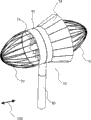
Fig. 9 is the stereogram according to hydraulic turbine generator of the present invention unit.
Figure 10 is the stereogram according to the flexible reinforcement cover of supravasal hydraulic turbine generator of the present invention.
Figure 11 is the stereogram of the hinged reinforcement cover of supravasal hydraulic turbine generator according to the present invention.
Figure 12 is the vector diagram that passes according to the fluid stream of the symmetrical fin of prior art.
Figure 13 is the flow graph that passes according to two contrarotating blade-sections of the two in-line arrangement turbine components of the conduct of prior art.
Figure 14 is the flow graph that passes according to four contrarotating blade-sections of the right parts of the cascade of the two in-line arrangement turbo machines of conduct of the present invention.
Figure 15 passes rotor blade part and by the flow graph according to the alternate position entrance and exit guide vane of the parts as turbo machine of the present invention.
Figure 16 passes two waterpower contrarotating blade-sections and by the flow graph according to the entrance and exit guide vane of the parts of the two in-line arrangement turbo machines of conduct of the present invention.
Figure 17 is the stereogram that is installed in the turbine generator unit on the extension type support according to of the present invention.
Figure 18 is the side view that is installed in the turbine generator unit on the extension type support according to of the present invention.
Figure 19 is the side view according to the turbine generator unit that hitches of the present invention.
Figure 20 is the sectional view of the edge of Figure 19 according to the I-I of single turbogenerator of the present invention.
Figure 21 is the sectional view of the edge of Figure 19 according to the II-II of single rotor dish turbogenerator of the present invention.
Figure 22 is the sectional view along the I-I of double rotor dish turbogenerator of Figure 19.
Figure 23 is the sectional view of the edge of Figure 19 according to the II-II of double rotor dish turbogenerator of the present invention.
Figure 24 is the side view that is installed in the turbine generator unit under the barge according to of the present invention.
Figure 25 is the planimetric map that is installed in the turbine generator unit in the minor dam according to of the present invention.
Figure 26 is the front view according to morning and evening tides fence of the present invention.
Figure 27 is the front view according to morning and evening tides fence of the present invention.
Figure 28 is the front view of the single turbogenerator in morning and evening tides fence according to the present invention.
Figure 29 is the sectional view of 3 turbogenerators that pile up in morning and evening tides fence or caisson among Figure 27.
Figure 30 illustrates the sectional view that utilizes the top door frame in orbit that is positioned at caisson to shift out the ability of maintenance of turbine generator unit with boxlike.
Embodiment
See also Fig. 1, there is shown the cut away view of the preferred embodiment of the present invention.Module conduits formula turbine generator unit 10 can be used as 10 uses of single turbine generator unit or uses with a plurality of turbine generator unit 10, typically be arranged in the tidal region, seabed, but this design can be used in other environment such as river, tailrace or wind energy unit.The purpose of turbine generator unit 10 is that the environmetal impact with minimum utilizes morning and evening tides to produce electric power effectively.The preferred embodiment is intended to arrange for the seabed.Clearly, the invention provides a kind of effective generator unit with minimum moving element.
Turbine generator unit 10 has two ends around center line and symmetry.Axis is in substantially parallel relationship to the hub 20 of direction of current 100 along the central shaft setting of turbogenerator 10.Hub 20 has hub head 21 at each end, and favourable mode is that the hub head can form with any fluid dynamic shape.Hub head 21 can be cusped arch shape or the lid with cusped arch shape, so that make the resistance minimum that enters and flow out pipe 40.
Root with a plurality of hydrofoil blade 30 of symmetrical section is connected to center hub 26, and the circumference of a plurality of hydrofoil blade 30 or end are connected to the permanent magnet seat ring that also is called rotor wheel rim 54 and comprise rotor disk 50 together.The first rotor dish 50 and second rotor disk 52 is coaxial installs with the front and back structure in a preferred embodiment.Rotor disk 50 and 52 only rotates along a direction owing to the hydrofoil shape of blade 30.Thrust-bearing 29 freely rotates between center hub 26 that is used for each rotor disk 50 and 52 and hub head 21 and butts up against both.Bearing preferred water lubricating low-friction thrust-bearing 29.Center hub or bearing spacer 28 rotatable and be arranged between the center hub 26 of two rotor disks 50 and 52 coaxially and separately rotor disk 50 and 52 to prevent that it from contacting with each other.Rotor disk 50 and 52 freely rotates around cage ring 28.
When the upstream rotor dish when the direction of current 100 is watched 50 will be all the time along a direction (clockwise or counterclockwise) rotation, and downstream rotor 52 is all the time along opposite direction rotation.When the directional steering of morning and evening tides and current 100, second rotor 52 will be the upstream, and because the hydrofoil shape continues edge and in the past identical direction rotation.Thereby, be two-way for current 100 turbine generator unit 10, and each rotor disk 50 and 52 rotates along same direction all the time.When turbine generator unit 10 had single rotor dish 50, it also rotated along single direction.
Blade 30 is from aerofoil profile or the hydrofoil of hub 26 with 90 ° of radially-protruding symmetries of cardinal principle.Blade 30 has top and lower surface and leading edge and trailing edge.The top of blade 30 and lower surface are usually perpendicular to current 100.Blade 30 can be provided with at the angle of inclination, for example is used to the blade structure that recedes.The quantity of blade 30 depends on the size of turbo machine.The aerofoil profile and/or the hydrofoil shape that can use liquid speed that each side of blade 30 is flow through in generation known in the art to change produce optimum lift and resistance thus.
Pipe 40 is arranged on around the axis of rotor 50 cylinder with the hollow that forms pipe, and holds rotor 50.Pipe 40 can be the cylinder of constant inner diameter, or inwall can converge so that increase the speed of the water that flows through pipe 40.In a preferred embodiment, the inwall of pipe 40 converges in core, produces Venturi effect thus when current 100 pass through pipe 40.Rotor wheel rim 54 allows a plurality of hermetically enclosed permanent magnets 56 to be connected to the outer rim of rotor disk 50 and 52.Rotor disk wheel rim permanent magnet seat ring is arranged in the recess of outside tube 40, and this recess holds hermetically enclosed stator coil 60.Second rotor 52 rotates along the direction opposite with the first rotor 50, so that reduce because the fluid momentum loss that eddy current produces, and makes turbine generator unit 10 more effective thus.Fixed stator coils 60 is installed in the pipe 40 of the external margin that is close to the rotor disk 50 that holds magnet 56.
Randomly, for gang operated and opposing lateral load, the magnet bearing arrangement can be used in rotor wheel rim 54, and this is well known in the art.Rotor wheel rim 54 is arranged in the magnet race in the pipe 40 or in the rotor wheel rim chamber 55 rotationally; the low friction of water lubrication skid plate (not shown) can be installed in the outside of rotor wheel rim 54; with protection stator coil 60, avoid the excessive deflection of rotor disk 50 and 52.
A plurality of bendings, normally the guide vane 24 of rectangle also supports as hub, extends to rotor case or pipe 40 with stable of forming that rotor disk 50 and 52 rotates thereon from hub 20.Guide vane 24 has general sharp keen leading edge, sharp keen trailing edge and two sides.Guide vane 24 provides the initial angle of the export orientation blade 24 of the afterbody that impacts upstream rotor dish 50 and downstream rotor dish 52, with the minimize fluid power eddy current loss of momentum.The surface of guide vane is with arc-shaped bend, so that the water of impact blades 24 changed direction with predetermined angle of attack degree before impact blades 30 in preferred enforcement.Blade 30 has the zero degree angle of attack with respect to rotor disk 50, and has the cross section of symmetry.
Turbine generator unit 10 is maintained fixed in position, and when morning and evening tides turned to and current 100 turn to thus, rotor began to rotate along its direction separately.Counter-rotating rotor dish 50 and 52 and the layout of guide vane 24 high efficiency electricity output is provided, stream 100 any directions from the rotor disk axle enter pipe 40 and make moving mechanical part minimum, have reduced maintenance expensive in the ocean environment thus.
Seeing also Fig. 2 below, is the detailed view after half of turbine assembly removed among the figure, wherein shows rotor disk hub 26, blade 30, permanent magnet rotor wheel rim 54, permanent magnet 56, stator coil 60, guide vane 24 and pipe 40.
Rotor disk moment by enter pipe 40, produce by passing the current 100 that guide vane that blade 30 produces lift provides the initial angle of attack, begin the rotation of the first rotor 50 thus.When leaving the first rotor 50, current 100 are with favourable angle of attack swirling flow and clash into second rotor 52, rotate second rotor 52 (referring to Fig. 1) along the direction opposite with the first rotor 50 thus.When the magnet in the rotor disk wheel rim 54 56 during through the fixed stator 60 in the conduits 40, according to Faraday's law, as well known in the art, the number of turn that the voltage of induction equals stator coil multiply by the variance ratio of magnetic flux.Then, can obtain electric current by manner known in the art by the cable (not shown).This generator 90 comprises rotor 50, magnet 56 and stator 60, can go between to produce direct current (d.c.) or threephase AC, as known in the art.Gap between magnet 56 and the stator 60 is full of peripheral working fluid, expensive thus and do not use aeroseal practically, this sealing is general uses inefficacy under water or needs higher maintenance, because higher fluid dynamic load is applied on the turbine generator unit.
Fig. 3 shows the front view of rotor disk 50, and rotor disk 50 has the prismatic blade 30 of wing chord size or the constant dimension from the root to the end.Blade 30 is to arrange with 20 1/4th strings in line of hub.All blades 30 all are cross section symmetry hydrofoils.Blade 30 can be from two to a plurality of n.
Fig. 4 is the front view of rotor disk 50, and the curved vane 30 of rotor disk 50 are narrower and broad endways at the hub place.Alternatively, can use 30 (not shown)s of the curved vane with narrow end at hub 20 place's broads.All blades 30 are cross section symmetry hydrofoils.The sweepback direction of blade 30 is rear portions of turbine generator unit hub 20 or towards the center of turbine generator unit hub 20, but sweepforward also is a kind of selection mode.Blade 30 can be two to more n.
Fig. 5 is the front view of turbomachine rotor disc 50, blade 30 and rotor wheel rim 54, wherein has the prismatic blade 30 with the constant chord size of 20 center lines in line of hub.Blade 30 can be two to more n.
Fig. 6 is the front view of rotor disk 50, rotor disk 50 have at hub 20 places narrower and endways broad prismatic blade 30.Alternatively, can use 30 (not shown)s of the prismatic blade with narrow end at hub 20 place's broads.All blades 30 are cross section symmetry hydrofoils.Blade 30 can be two to more n.
Fig. 7 is the front view of rotor disk 50, blade 30 and rotor wheel rim 54 (referring to Fig. 1), wherein has vertical offset distance blade and marine organisms bypass tube 32.Marine organisms bypass tube 32 is the vertical holes by the central shaft of hub 20, can pass through if enter turbine generator unit 10 by this hole such as fish and mammiferous marine organisms.Bypass tube 32 is possible, because rim turbine generator unit 10 makes hub 20 only be used as the rotor disk 50 of back shaft and not hold generator 90 as a small construction.
Fig. 8 is the sectional view of layout with the turbomachine rotor disc on the curved surface that is used for rotor disk 50 rather than plane.This layout can be used with the blade 30 of constant thickness or thickening degree.This layout can be used with single or multiple rotor disks and with any layout of the rotor blade 30 of earlier drawings.
Fig. 9 is the stereogram of the preferred embodiment of the present invention.Turbine generator unit 10 can be by general elliptoid filter screen 70 encapsulation that are connected to tube end 40.Filter screen 70 can by a plurality of from pipe 40 vertically stretch out and before two hub 20 ends, on, the next door or under the bar that intersects of point form.The effect of filter screen 70 is to make halobiontic intrusion minimum and be used to prevent that sea grass, fragment and marine life from entering the guard shield of turbine generator unit 10, otherwise they can block or damage turbine bucket 30 and guide vane 24.Because the shape of filter screen and morning and evening tides and current 100 change direction, filter screen 70 can self-cleaning.Reinforcement cover 74 comprises the hinged panel 36 that has around the hinge 37 (not shown among Fig. 9) of vertical midplane of the circumference of turbine generator unit 10.
Referring again to Fig. 7, when filter screen 70 is used in combination with marine organisms bypass tube 32, filter screen 70 stops and extends to the leading edge of pipe 40 at the external margin of bypass tube 32 mouths, thus, when fragment is attached in the filter screen 70, marine organisms can pass through turbine generator unit, reduce the influence of generating to environment thus.
Refer again to Fig. 9, the turbine assembly of being made up of rotor disk 50 (and 52 (if applicable)) (not shown at this) and generator can be used as a unit and inserts or take out so that be convenient to safeguard, and pipe 40 and inking device stay in position.Rotor disk 50 and generator 90 (not shown at this) can be the self-contained core units that has bump or hook on top surface.Be provided as the pipe edge isolation sheet 44 of the flexible core of pipe 40, so that can remove turbine assembly.In case remove pipe edge isolation sheet 44, turbine assembly 48 can rise to the surface, to safeguard or to change.
Figure 10 shows the pipe 40 of the flexible reinforcement cover 74 with the mid point that is connected turbogenerator 10.By such as Spectra
TMThe cover 74 that the durable flexible material of braided fiber is made so forms, and promptly flows 100 kinetic pressure and will force cover 74 to suitable position, covers the outlet of 74 flared ends at pipe 40.Cover 74 can have embedding stiffening ring (not shown) wherein, but will necessarily have rigidity shroud ring 75 in its maximum and end diameter place, and the bigger kinetic pressure that is subjected to tidal flow 100 with box lunch is made the suitable shape of time spent maintenance.Cover 74 can be made up of durable composite material or metal hinging par such as " Spectra braided fabric ".Cover 74 has bigger circumference at trailing edge, thereby it opens from pipe 40.Cover 74 produces the area of low pressure in the outlet of turbine generator unit 10, makes thus because the turbine efficiency loss that the Betz effect produces is minimum.Such fixedly booster increases the flow by turbo machine, and has characteristics known in the art.Flexible fabric and hinged metal covering 74 are all moved to and fro by the power of tidal flow when morning and evening tides changes direction, stretch out backward on the outlet of the outlet of pipe 40 or pipe 40 all the time thereby cover 74.This is the reinforcement cover 74 of two-way independent location, and this reinforcement cover 74 is hinged or fixing around the middle part of turbo machine pipe 40 circumference.Cover can be installed around whole circumference, if or concrete the installation need, can install around the part of circumference just, or install around a plurality of unit.
Figure 11 shows has the pipe 40 of hinged reinforcement cover 74 that is connected the mid point of turbine unit 10 by hinge 37.Cover 74 is made of durable rigid panel 36 and is located by the kinetic pressure of stream 100, and stream 100 will force cover 74 to suitable position, and the end of cover expansion partly is positioned at the outlet of pipe 40.Turbine generator unit 10 is made of pipe 40 structure and materials, and the buoyancy that is beneficial to layout and housekeeping operation is provided thus.
Turbine generator unit is made of durable corrosion-resistant material.In a preferred embodiment, overall structure is that the inner concrete of strengthening the ocean grade of gathering materials of the lightweight that comprises abundant ratio of positive buoyancy is used for rotor 50 and axle and other critical piece that pipe 40 and anti-corrosion and high strength material are used to constitute turbo machine 10.Can use composite material, concrete and steel such as the advanced person.As known in the art, turbine generator unit 10 coating silica glass products, minimum to reduce the water conservancy loss and marine organisms are adhered to the fouling that causes.
The silica glass product that pipe 40 coating is new and preferably being formed by the floaty concrete of lightweight makes turbine generator unit 10 can be dragged to the building site layout, hitches the predetermined depth under water surface 16 so that turbine generator unit 10 is floated then.Turbine generator unit 10 is reduced to the desired locations in river or seabed.In a preferred embodiment, turbine generator unit is used the tide generating forces generating.
Figure 12 is the vector diagram of air-flow that passes the symmetrical wing of prior art, wherein at U. S. Patent 4,221, Wells illustrates the driving vector in the hydrofoil cross section of passing blade 30 in 538, wherein V is the relative velocity of the stream opposite with the direction of blade 30, I1 and I2 are resultant current voxel vector approach stream velocities, and U1 and U2 represent bimodal current 100, and L1 and L2 represent the normal component of lift.The lift that passes hydrofoil blade 30 is with effective and strong mode accelerating rotor 50.
Figure 13 is the flow graph of two waterpower contrarotating blade 30 parts that passes as the parts of the turbine generator unit with two coaxial rotor dishes 50.The system of the prior art has reduced effectively because the downstream energy loss that eddy current causes and increased operating efficiency on the bigger velocity range.
Figure 14 is the right flow graph of cascade that passes coaxial rotor 50 turbine generator unit.Use a plurality of cascades to make for very high-speed scope and pass multiunit pressure decline minimum.The right quantity of the cascade of contrarotating dish is two or more n.
Figure 15 passes single rotor dish 50 with hydrofoil blade 30 and the flow graph that passes through alternate position entrance and exit guide vane 24.Blade 24 is flexible and by the connecting rod control with hinged cap.The kinetic pressure of stream 100 is regulated cover, thus guide vane is moved to suitable position.The upstream guide vane will provide high incidence and the downstream guide vane will reduce the momentum eddy current loss.When current 100 turn to, rotor 50 rotates with identical direction, but blade 24 occupies the position shown in the dotted line 25 by articulation steering or upset.In this variation, the leading edge of blade 24 is rigidly fixed to the internal surface of hub 20 structures and pipe 40.
Figure 16 passes two waterpower contrarotating blade 30 parts and by the flow graph as the entrance and exit guide vane 24 of the parts of two in-line arrangement rotor 50 turbine generator unit.In a preferred embodiment, guide vane 24 is with illustrated structure permanent fixation.
Figure 17 is mounted in the stereogram of the turbine generator unit 10 on the extension type support 80.In a preferred embodiment, turbine generator unit 10 is installed on the support 80, and support 80 can be telescopic, highly regulates so that can realize the remote control of turbine generator unit 10, comprises turbine generator unit 10 is elevated on the water surface 16, so that safeguard.
Figure 18 is mounted in river or the tidal flow front view of the turbine generator unit under water a plurality of extension type supports 80.By rising or reducing telescoping shoring column 80 to have made things convenient for installation, dismounting and maintenance near turbine generator unit.Can use two coaxial rotor dishes 50 and 52, and the turbine generator unit 10 on 80 groups on the other same support is set.Can use any known cable system to obtain electric power and control turbine generator unit 10.
Figure 19 is the side view that ties up to the turbine generator unit of 14 groups on two or more anchors on ocean or the riverbed 15 by outside bump and cable 13.Anchor can be comprising of any kind of a zinc-plated steel ship anchor or concrete block.Cable 13 is connected to each end of turbine generator unit 10, and turbogenerator 10 keeps in position thus.Because rotor 50 and 52 is two-way, turbine generator unit can remain on fixing position.
Figure 20 is the sectional view along the I-I of single rotor 50 turbogenerators of Figure 19.
Figure 21 is the sectional view along the II-II of single turbine generator unit of Figure 19.
Turbine generator unit 10 can be single or be used with the group of two or more turbine generator unit 10.
Figure 22 is the sectional view along I-I of Figure 19, wherein shows two variation of turbine generator unit 10 side by side of the present invention.
Figure 23 is two end view of Figure 19 of the variation of turbine generator unit 10 side by side.The pipe 40 of two turbine generator unit 10 can welding, bolt or is suitable for bearing hydrokinetic device by any other and links together.
Have at least five kinds of possible expections to be used for the method for arranging of turbine generator unit 10.These methods are:
● shown in Figure 17 and 18, be installed on one or more jack columns 80
● under barge 120, float or be connected to barge 120
● on rubber dam 130 next doors of the collapsible of the side in river
● floating as shown in figure 19 ties up under the surface, and
● be shown in the morning and evening tides fence that passes bay, ocean or air route as Figure 26-30
Figure 24 is the side view that is installed in the turbine generator unit 10 under the barge 120 according to of the present invention.
Figure 25 is the planimetric map that is installed in the turbine generator unit 10 in the minor dam 130 according to of the present invention.
Figure 26 is the front view of whole morning and evening tides fence 140, there is shown according to a few row's turbine generator unit 10 of the present invention.
Figure 27 is the close-up view of the part of morning and evening tides fence 140, there is shown according to nine turbine generator unit that stack 10 of the present invention.
Figure 28 is the front view of the single turbine generator unit 10 in morning and evening tides fence 140 according to the present invention.
Figure 29 is the sectional view of 3 turbine generator unit of piling up 10 in the structure of morning and evening tides fence 140.Morning and evening tides fence 140 according to the present invention has tee girder structure 141, and electricity and monitor big canoe and relevant roadbed 142 is 147 that assist by vertical support column, comprise tee girder 143, access cover 144, and the column deck structure of rail line 145 and 146.Morning and evening tides fence 140 comprises ripple shunt 148 and removable anti-cavitation platform 149, gravity fondational structure 150 and corresponding supporting network 151 and support 152 and 153 in addition.The a plurality of turbine generator unit 10 of this support structure.
Figure 30 shows that the door frame on the guide rail that utilizes the top that is positioned at morning and evening tides fence 140 structures shifts out the sectional view of the ability of maintenance of turbine generator unit with boxlike.
Above preferred embodiment is not detailed or scope of the present invention is limited in disclosed form accurately.Select and these embodiments are described so as to illustrate best principle of the present invention with and use and actual the use, make other personnel of related domain understand this instruction.
Under the situation that does not depart from the spirit or scope of the present invention, those of ordinary skill in the art can carry out many changes and modification according to the content of above-mentioned disclosure in practice of the present invention.Therefore, scope of the present invention limits according to the content that claim limits.