EP1878571A2 - Unité d'impression d'une presse rotative - Google Patents
Unité d'impression d'une presse rotative Download PDFInfo
- Publication number
- EP1878571A2 EP1878571A2 EP07110296A EP07110296A EP1878571A2 EP 1878571 A2 EP1878571 A2 EP 1878571A2 EP 07110296 A EP07110296 A EP 07110296A EP 07110296 A EP07110296 A EP 07110296A EP 1878571 A2 EP1878571 A2 EP 1878571A2
- Authority
- EP
- European Patent Office
- Prior art keywords
- printing
- printing unit
- forme
- unit
- handling device
- Prior art date
- Legal status (The legal status is an assumption and is not a legal conclusion. Google has not performed a legal analysis and makes no representation as to the accuracy of the status listed.)
- Granted
Links
Images


Classifications
-
- B—PERFORMING OPERATIONS; TRANSPORTING
- B41—PRINTING; LINING MACHINES; TYPEWRITERS; STAMPS
- B41F—PRINTING MACHINES OR PRESSES
- B41F27/00—Devices for attaching printing elements or formes to supports
- B41F27/12—Devices for attaching printing elements or formes to supports for attaching flexible printing formes
- B41F27/1206—Feeding to or removing from the forme cylinder
-
- B—PERFORMING OPERATIONS; TRANSPORTING
- B41—PRINTING; LINING MACHINES; TYPEWRITERS; STAMPS
- B41P—INDEXING SCHEME RELATING TO PRINTING, LINING MACHINES, TYPEWRITERS, AND TO STAMPS
- B41P2227/00—Mounting or handling printing plates; Forming printing surfaces in situ
- B41P2227/50—Devices for storing printing plates
-
- B—PERFORMING OPERATIONS; TRANSPORTING
- B41—PRINTING; LINING MACHINES; TYPEWRITERS; STAMPS
- B41P—INDEXING SCHEME RELATING TO PRINTING, LINING MACHINES, TYPEWRITERS, AND TO STAMPS
- B41P2227/00—Mounting or handling printing plates; Forming printing surfaces in situ
- B41P2227/60—Devices for transferring printing plates
Definitions
- the invention relates to a printing unit of a rotary printing press according to the preamble of claim 1.
- DE 44 42 265 A1 is a transport system for transporting printing forms known, with printing forms z. B. between their Bereciungsstation and printing units of a printing machine and can be transported hert, each printing plate z on the respective belonging to one of the printing units form cylinder. B. is changed with a respective printing unit associated handling device.
- the DE 44 42 574 A1 relates to a method and apparatus for providing a printing plate, wherein a robot serially populates printing plate memory with printing plates, wherein in a pivotal movement all printing plates stored in the printing plate memory are moved together to a waiting position close to a plate cylinder. An assembly of the printing plate storage, in which the printing plate storage a plurality of printing plates are supplied simultaneously, is not provided.
- the invention has for its object to provide a printing unit of a rotary printing press on which a fast and reliable change of printing forms is executable, the printing unit for the operator of the rotary printing machine remains easily accessible.
- the achievable with the present invention consist in particular that printing form magazines a printing unit can be charged quickly and reliably with printing plates.
- the feeding of printing forme magazines is carried out program-controlled independently of a running production process, without the need for manual intervention on an operating side of the rotary printing press.
- the handling device used for feeding the printing forme magazines is designed such that, due to its only temporary presence, ie. H. their relatively short residence time at the relevant operating side of the printing unit does not adversely restrict access to their printing units and neither endangers nor hampers operating personnel of the rotary printing press in their respective working area.
- all printing form magazines of the rotary printing press can be equipped with new printing forms simultaneously, so that z. B.
- the proposed solution contributes to the reduction of set-up times by automating operations on a rotary printing press, while still ensuring a high degree of flexibility in terms of the printing forms to be executed in the printing process.
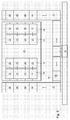
- Fig. 1 shows an example as a tower, in particular designed as an eight-tower, z. B. in a frame 24 enclosed printing unit 01 a preferably used for colored newspaper printing rotary printing machine, wherein the printing unit 01 is designed in a very compact design, ie in particular with a low overall height.
- a pressure unit 01 designed as a 16-tower two such four-high towers can also be arranged.
- each printing unit 03 is also equipped with a plurality of rollers preferably zoneless inking unit 07, z. B. with an anilox roller having a short inking unit 07, wherein the rollers of the inking 07 formed from a color reservoir ink to form a thin ink film and this color film in its layer thickness uniform and transport to each forme cylinder 06 order order on at least one arranged on the forme 06 printing form.
- the respective forme cylinder 06 of each printing unit 03 has an axial Length in the range z. B.
- the rotary printing press shown by way of example in FIG. 1 preferably prints in a dry offset printing process, ie in an offset process without using a dampening solution, which is why the printing couples 03 shown in FIG. 1 each have no dampening unit.
- each of the printing units 03 of the printing unit 01 has in each case a printing forme magazine 08, wherein the respective printing forme magazine 08 is in each case associated with the forme cylinder 06 of the respective printing unit 03.
- Each printing forme magazine 08 has at least one storage position for storing at least one printing form, wherein the respective storage position can be preferably realized in each case in a shaft or through a shaft, said shaft preferably a z.
- Each printing forme magazine 08 preferably also has a shaft with a likewise preferably remote-controlled conveyor for discharging at least one used printing forme from the forme cylinder 06.
- each slot of the printing forme magazine 08 each has a plurality of storage positions for receiving a plurality of the forme cylinder 06 to be fed pressure forms and / or in the respective printing forme magazine 08 also several storage positions for the forme cylinder 06 discharged Printing forms are provided.
- the printing forms to be recorded at several storage positions of the respective shaft, ie the new or the used printing plates can be stored in the respective slot in each case in a batch process, wherein the respective forme cylinder 06 z. B. fed sequentially or be discharged sequentially from this forme cylinder 06.
- the respective printing forme magazines 08 may be fixedly mounted in the printing unit 01 fixed or they are by a preferably remotely controllable movement, for. B. brought by a pivoting movement from a rest position into a working position with that forme cylinder 06, to which they are respectively assigned, if necessary, in an operative connection to perform the process of supplying or discharging of at least one printing plate.
- the operative connection between the printing forme magazine 08 and the associated forme cylinder 06 can, for. B. be prepared that the respective printing forme magazine 08 with its longitudinal extent (Fig. 1 and 2) is preferably made tangential to the respective forme cylinder 06, wherein the longitudinal extent of the respective printing forme magazine 08 preferably substantially horizontally, ie with a tolerance of z. B.
- the operative connection between the printing forme magazine 08 and the associated forme cylinder 06 is z. B. thereby repealed that the respective printing forme magazine 08 is turned off by the respective forme cylinder 06 such that the change of a printing form from the printing forme magazine 08 to the respective forme cylinder 06 z. B. is not executable because of too large a distance between the printing forme magazine 08 and the respective forme cylinder 06 or an inappropriate alignment between them.
- the operative connection between the printing forme magazine 08 and the forme cylinder 06 assigned to it there is either a touch contact or a mouth region of the printing forme magazine 08 located at a distance of only a few millimeters from the lateral surface of the relevant forme cylinder 06.
- the operative connection between the printing forme magazine 08 and the associated forme cylinder 06 can, for. B. also be made or canceled by a control unit that respective printing forme magazine 08 releases in his on the change of a printing form related function or locks, wherein the respective printing forme magazine 08 preferably not changed in its spatial arrangement to the respective forme cylinder 06.
- the respective printing forme magazines 08 have z. B. at its side facing away from the forme cylinder 06, that is, at the opposite end of its mouth region in each case at least one z. B. slot-shaped opening through which at least one new printing form their respective storage position in the printing forme magazine 08 can be fed, wherein at a slot-shaped opening whose parallel to the axial direction of the forme 06 extending slot width a multiple, z. B. is at least threefold of their orthogonal slot height.
- the respective printing forme magazine 08 can have a corresponding number of memory positions arranged next to one another.
- a plurality of printing forme magazines 08 of the type described above are arranged next to one another in the case of a plurality of pressure molds arranged side by side in the axial direction of the respective forme cylinder 06 in the axial direction of the respective forme 06.
- 6/2-forme cylinder 06 each equipped with printing plates, wherein one in its axial direction at six juxtaposed mounting locations and in its circumferential direction at two consecutively arranged mounting locations each with a printing plate assignable forme cylinder 06 is referred to as 6/2 forme cylinder 06.
- a printing unit 01 printing on both sides of the printing material 02 with four printing inks is referred to as a 4/4 printing unit.
- the printing plates are each arranged by means of a respective form cylinder 06 preferably arranged remotely operable holding device, for. B. a clamping device, attached to the respective form cylinder 06.
- the holding device is z. B. pneumatically actuated and arranged in a channel of the respective forme cylinder 06, wherein this channel extends in the axial direction of the respective forme cylinder 06.
- the handling device 09 is designed as a controlled, automatically reacting movement device, ie as a controlled, preferably program-controlled automaton 09, the handling device 09 arranged on the same operating side of the printing unit 01 in different levels Druckformmagazine 08 in an automated sequence each with the at least one Fed printing form.
- the handling device 09 by its controlled movement on the same operating side of the printing unit 01 arranged in different levels Druckformmagazines 08 each at least one of her gripped, ie held printing form a particular storage position of the respective printing forme magazine 08 pinpoint, the handling device 09 preferably each printing plate each with their respect to the production direction of the female cylinder receiving 06 leading end of the respective printing forme magazine 08 feeds.
- the handling device 09 thus preferably guides each printing plate in each case with its leading end with respect to the direction of production of the female cylinder 06 receiving end through the opening of the respective printing forme magazine 08 in the storage position provided in this printing forme magazine 08.
- the handling device 09 is positioned on or in front of the corresponding operating side of the printing unit 01.
- Each operating side of the printing unit 01 comprises at least the working area or handling area of the operating personnel on this printing unit 01, the operating side Operating personnel Access to the respective forming cylinders 06 and printing forme magazines 08 allows to perform work on the forme 06 and printing forme magazines 08.
- the respective handling device 09 feeds z. B. several arranged on the same operating side of the printing unit 01 in different preferably horizontally extending planes of this printing unit 01 Druckformmagazine 08 simultaneously with at least one new printing plate. Additionally or alternatively it can be provided that with the respective handling device 09 more, preferably all storage positions of the same forme cylinder 06 associated printing plate magazine 08 are each loaded simultaneously with a new printing plate and are loaded accordingly, so z. B. on a 6/2-form cylinder several, preferably all of the twelve mounting locations corresponding memory positions of this form cylinder 06 associated printing forme magazine 08 are each loaded simultaneously with a new printing form.
- the handling device 09 is preferably only temporarily present on or in front of the relevant operating side of the printing unit 01, namely only for carrying out the charging process or for discharging printing forms that are no longer required.
- the handling device 09 preferably has in each case one at least one printing form vertically transporting lifting device, each of the printing forms to be transported is preferably transported in each case with an at least vertically movable platform 11 to that preferably horizontal plane on which the printing forme magazine 08 to be loaded at least with its at least is located a new printing form receiving storage position.
- the movable at least one printing plate movable platform 11 is guided in its vertical movement, preferably based on z. B. laterally on the platform 11 arranged rails 12, z. B. of at least two rails 12 which are arranged parallel to each other, extend vertically and are preferably mounted in each case in or on the frame 24 of the printing unit 01 stationary.
- a lifting means for the execution of Lifting movement of the at least one platform 11 of the lifting device can, for. B. at least one chain, a toothed belt, a belt or a spindle gear can be provided, wherein the lifting means is preferably formed as at least one pair of the aforementioned means.
- a platform 11 assigned to a specific assembly site on one of the forme cylinders 06 can receive and transport several, in particular two, printing forms, these printing forms being moved vertically by the same platform 11 preferably being provided for mounting on the same forme cylinder 06 in its circumferential direction, wherein printing forms conveyed by the same platform 11 are transferred sequentially or simultaneously to the printing forme magazine 08 assigned to the forme cylinder 06 for feeding its storage positions.
- Several printing forms stored in the same printing forme magazine 08 at different storage positions, which are provided for mounting at the same axial position of the forme magazine 08 assigned to this printing forme magazine 08, are fed sequentially to this forme cylinder 06 from the respective storage position of the printing forme magazine 08 and thus also sequentially in the circumferential direction of the relevant forme cylinder 06 mounted.
- a handling device 09 is provided on both operating sides of the printing unit 01, the printing unit 01 having on each of its operating sides a plurality of printing units 03, each arranged in different preferably horizontal planes, wherein in each of these planes at least one printing forme magazine to be charged in each case with at least one printing forme 08 is provided.
- Each of these handling devices 09 can each have at least one movable platform 11 guided in its vertical movement, preferably several of these platforms 11.
- an electric motor or a pneumatic drive is preferably remotely operable.
- the at least one Platforms 11 for transporting the same handling device 09 are stacked one above the other in the respective handling device 09 and can be moved individually only in their entirety, ie in a rigid composite as a package (FIG. 1) or in a stack-fanning manner (FIG. 2) , Wherein, in the case of their mobility in a rigid composite, the at least one to be loaded printing forme magazine 08 having horizontal levels one after the other, ie sequentially approached by the drive simultaneously moving platforms 11 and wherein in the case of their individual mobility of these platforms 11 moves sequentially and each of these platforms 11 of the respective handling device 09 is assigned to a single specific horizontal plane, in such a way that z. B.
- the respective platforms 11 of the respective handling device 09 After an executed change of at least one printing plate at a arranged in the respective horizontal plane of the printing unit 01 printing forme magazine 08, the respective platforms 11 of the respective handling device 09 from the respective drive back to their original position in a range z. B. driven above the printing unit 01, where the respective platforms 11 are stacked again stacked in the form of an assembled package.
- the starting position for the lifting movement of the platforms 11 of the handling device 09 in an area above the printing unit 01 can also be provided that the starting position for the lifting movement of the platforms 11 of the handling device 09 below z. B.
- a memory 13 which is also vertically movable by the handling device 09 can be provided for receiving used printing forms, this memory 13 receiving printing forms taken from the respective forme cylinders 06 and stored in the associated respective printing form magazines 08 and these from the printing units 03 of the printing unit 01 transported away.
- the used printing form receiving memory 13 is preferably formed as a collecting memory 13, because for used printing plates in terms of their inclusion in the memory 13, the observance and compliance with a particular order is not required.
- the used printing plates from all preferably horizontal planes of the printing unit 01 receiving accumulator 13 is in the handling device 09 z. B. arranged below the bottom platform 11.
- the handling device 09, the conveyors of the respective printing forme magazines 08 and preferably also the respective Holding devices of the forme cylinder 06 are z. B. from one of the printing unit 01 associated (not shown) control unit or operating unit, for. B. controllable from a control station of the rotary printing press or operable.
- Fig. 3 shows schematically in a simplified representation of the printing unit 01 of Fig. 1 or 2 in a plan view, said printing unit 01 is incorporated into a transport system for her to be supplied or discharged from her printing forms.
- An imaged in an imaging system (not shown), d. H. provided with afor printing plate is in preparation for their subsequent attachment to one of the printing unit 01 associated with the forme cylinder 06 preferably at two of its opposite ends z.
- B. rail-bound preferably remotely controllable conveyor 14 of the transport system to the printing unit 01 transported, wherein the transport of the printing plate preferably horizontally, d. H. in its lying state.
- the printing plates required in the printing unit 01 are transported in this way with the conveyor 14 of the transport system sequentially to the printing unit 01.
- the transport system may have at least one buffer store in which imprinted printing plates in the imaging system can be stored until they are transported to the printing unit 01.
- imaged printing forms belonging to a plurality of different editions can be stored until the production of the respective edition on the printing unit 01 is pending for execution.
- the use of a buffer eliminates the need to transport imaged printing plates in each case directly from the imaging system to the printing unit 01.
- Each of the printing forms to be transported to the printing unit 01 with the conveying device 14 of the transport system is in each case provided with an encoding (not shown) so that it is addressed and assigned to a specific installation location in the Pressure unit 01 is uniquely assigned.
- a code reader detects the encoding of the printing form and an identification system (not shown) using this code reader has identified a printing unit transported to the printing unit 01 as belonging to this printing unit 01
- the printing form conveyed by the conveying device 14 becomes the area of the printing unit 01 taken and there automatically guided by a transport device depending on their addressing to one of the operating pages of the printing unit 01, ie to the right or left side of the operation shown in Fig. 3 in its plan view printing unit 01.
- each of these printing plates has a respective leading end in its direction of production and a trailing end in its direction of production. Since each printing plate is to be supplied with its leading end a printing forme magazine 08 and then their respective forme cylinder 06, which transported with the conveyor 14 of the transport system to the printing unit 01 transported printing form on its transport to one of the two operating sides of the printing unit 01 to a perpendicular to the Working surface of the printing plate standing axis are turned by 180 °, which is arranged with a transport path in the printing forme, z. B. as a turntable 16 formed turning device 16 is done.
- Parallel to the axial direction of the forme cylinder 06 are preferably on both sides of the printing unit 01 preferably in a region outside of the respective operating side of the printing unit 01 working area of the operator of the rotary printing machine a distributor 17 for distributing the printing unit 01 transported printing forms on the printing units 03 this Pressure unit 01 is provided, wherein the distribution device 17 on each of the two operating sides of the printing unit 01 each transported to the printing unit 01 printing form according to their respective addressing in each case an axial mounting positions with respect to this printing form later receiving cylinder 06 assigns, the distribution device 17 in the axial direction of the respective forme cylinder 06th so many subjects 18 next to each other arranged, as are provided with respect to these forme cylinder 06 axial mounting positions, said subjects 18 are successively filled with the conveyer 14 brought about pressure forms.
- each printing form held in one of the compartments 18 is preferably transferred under program control to a platform 11 of the handling device 09 corresponding to the axial mounting position.
- all printing forms held in the respective compartments 18 by one of the distributing devices 17 are simultaneously transferred to the platforms 11 of the handling device 09 corresponding to the respective axial assembly position.
- the transfer of the in the respective compartments 18 held by one of the distributing devices 17 printing forms to the respective with respect to the axial mounting position corresponding platforms 11 of the handling device 09 may, for. B. by the use of one or more of the respective distribution device 17 from acting, preferably remotely operated slide. Since the transfer of the in the respective compartments 18 held by one of the distributing devices 17 printing forms to the respective corresponding to the axial mounting position platforms 11 of the handling device 09 regardless of the operation of the printing units 03 this printing unit 01, this transfer can easily during an ongoing production the rotary printing machine done.
- the transfer of the held in the respective compartments 18 of one of the distributing devices 17 printing forms to the respective with respect to the axial mounting position corresponding platforms 11 of the handling device 09 is z. B. during an ongoing production of the printing unit 01.
- the respective transport direction of the printing plates is indicated in Fig. 3 in each case by directional arrows.
- the change of at least one held in one of the platforms 11 of the handling device 09 printing forms with one of the printing forme magazines 08 of the printing unit 01 can be carried out automatically during the current production of the rotary printing press, without manual intervention of the rotary press operating operator is required. In the same way, but with opposite direction of movement can be removed in the printing unit 01 no longer used printing plates using the respective handling device 09 and distributor 17 from the printing unit 01 and finally transported away with the conveyor 14 of the transport system.
- Access to the printing units 03 of the printing unit 01 is to be shut off only for the period against the access of operating personnel using this rotary printing press, in which the respective handling device 09 positions at least one of their respective platforms 11 in the horizontal plane of one of the printing forme magazines 08 of this printing unit 01, wherein this period may be very short due to a preferably fully automated sequence of the change of at least one printing plate between the platform 11 of the handling device 09 and the respective printing forme magazine 08 and z. B. may be in the lower single-digit minute range.
- the respective handling device 09 can also simultaneously exchange all printing forms deposited on their respective platforms 11 with the respective corresponding printing forme magazines 08, whereby this parallel loading process of the printing forme magazines 08 understandably requires less time than a sequential, mechanically or manually executed charging of the printing forme magazines 08.
- the respective handling devices 09 can be brought simultaneously on both sides of the printing unit 01 used, which further accelerates the process of loading the printing forme magazines 08 of this printing unit 01.
- a memory 19 acting as a waste memory 19 for receiving at least one printing forme provided this memory 19 also like the same handling device 09 belonging distribution device 17 in the axial direction of the respective forme cylinder 06 preferably has a plurality of juxtaposed compartments 21.
- the memory 19 serves to receive at least one printing forme, which is replaced with respect to an axial mounting position of at least one forme cylinder 06 by another, more recent, provided for this mounting position printing form.
- the the Updating printing form is preferably transported as well as the other on at least one of the forme 06 of this printing unit 01 to be mounted printing forms by means of the conveyor 14 of the transport system to the printing unit 01 and then fed via the distributor 17 of the respective handling device 09.
- a printing form serving for updating is preferably transported with a high priority, ie primarily to the respective handling device 09 and then further to the respective printing forme magazine 08, where it is recorded in the printing process.
Applications Claiming Priority (1)
| Application Number | Priority Date | Filing Date | Title |
|---|---|---|---|
| DE200610032199 DE102006032199A1 (de) | 2006-07-12 | 2006-07-12 | Druckeinheit einer Rotationsdruckmaschine |
Publications (3)
| Publication Number | Publication Date |
|---|---|
| EP1878571A2 true EP1878571A2 (fr) | 2008-01-16 |
| EP1878571A3 EP1878571A3 (fr) | 2010-06-30 |
| EP1878571B1 EP1878571B1 (fr) | 2012-12-19 |
Family
ID=38606596
Family Applications (1)
| Application Number | Title | Priority Date | Filing Date |
|---|---|---|---|
| EP20070110296 Not-in-force EP1878571B1 (fr) | 2006-07-12 | 2007-06-14 | Unité d'impression d'une presse rotative |
Country Status (2)
| Country | Link |
|---|---|
| EP (1) | EP1878571B1 (fr) |
| DE (1) | DE102006032199A1 (fr) |
Cited By (2)
| Publication number | Priority date | Publication date | Assignee | Title |
|---|---|---|---|---|
| EP1987953A2 (fr) * | 2007-05-02 | 2008-11-05 | manroland AG | Procédé de manipulation de plaques d'impressions et presse rotative |
| EP2153994A2 (fr) * | 2008-08-01 | 2010-02-17 | manroland AG | Machine d'impression rotative |
Families Citing this family (6)
| Publication number | Priority date | Publication date | Assignee | Title |
|---|---|---|---|---|
| DE102008045679A1 (de) * | 2008-04-29 | 2009-11-05 | Manroland Ag | Rollendruckmaschine, Verfahren zur Handhabung von Druckplatten an einer Rollendruckmaschine und Verfahren zum Betreiben einer Rollendruckmaschine |
| DE102008044228B4 (de) | 2008-12-01 | 2012-11-08 | Koenig & Bauer Aktiengesellschaft | Druckeinheit mit mindestens einem an ihrer mindestens einen Bedienseite angeordneten Druckformmagazin mit einem diesem Druckformmagazin zugeordneten Formzylinder |
| DE102009000750B4 (de) | 2009-02-10 | 2011-07-21 | KOENIG & BAUER Aktiengesellschaft, 97080 | Druckformzuführung und ein Verfahren zum Transport zumindest einer Druckform |
| DE102010000994B4 (de) | 2010-01-19 | 2014-05-22 | Koenig & Bauer Aktiengesellschaft | Verfahren zum Zuführen und/oder Abführen von Material einer Druckmaschine |
| DE102010042100A1 (de) * | 2010-10-07 | 2012-04-12 | Koenig & Bauer Aktiengesellschaft | Transportsystem in einer Druckeinheit für den Transport mindestens einer neu auf einem Formzylinder der Druckeinheit aufzubringenden Druckform sowie Druckeinheit mit einem Transportsystem |
| EP2552697B1 (fr) | 2010-10-07 | 2014-03-19 | Koenig & Bauer AG | Unité d'impression avec un système de transport et système logistique dans une imprimerie |
Citations (4)
| Publication number | Priority date | Publication date | Assignee | Title |
|---|---|---|---|---|
| DE3630876A1 (de) | 1985-09-12 | 1987-03-19 | Tokyo Kikai Seisakusho Ltd | Produktionsprozesssteuersystem fuer eine zeitungsdruckvorrichtung |
| US4727807A (en) | 1985-09-30 | 1988-03-01 | Tokyo Kikai Seisakusho | Apparatus for automatically mounting and removing printing plates in rotary printing press |
| DE4442265A1 (de) | 1994-11-28 | 1996-05-30 | Roland Man Druckmasch | Transportsystem zum Transport von Druckformen |
| DE4442574A1 (de) | 1994-11-30 | 1996-06-05 | Koenig & Bauer Albert Ag | Verfahren und Vorrichtung zur Bereitstellung einer Druckplatte |
Family Cites Families (3)
| Publication number | Priority date | Publication date | Assignee | Title |
|---|---|---|---|---|
| JP2724668B2 (ja) * | 1993-09-24 | 1998-03-09 | 株式会社東京機械製作所 | 刷版配送装置 |
| DE10314344B3 (de) * | 2003-03-28 | 2004-08-26 | Koenig & Bauer Ag | Vorrichtung zum Speichern eines einem Zylinder einer Druckmaschine zuzuführenden Aufzugs |
| DE102004052020B8 (de) * | 2004-10-26 | 2013-07-04 | Wifag Maschinenfabrik Ag | Druckformmanipulator |
-
2006
- 2006-07-12 DE DE200610032199 patent/DE102006032199A1/de not_active Withdrawn
-
2007
- 2007-06-14 EP EP20070110296 patent/EP1878571B1/fr not_active Not-in-force
Patent Citations (4)
| Publication number | Priority date | Publication date | Assignee | Title |
|---|---|---|---|---|
| DE3630876A1 (de) | 1985-09-12 | 1987-03-19 | Tokyo Kikai Seisakusho Ltd | Produktionsprozesssteuersystem fuer eine zeitungsdruckvorrichtung |
| US4727807A (en) | 1985-09-30 | 1988-03-01 | Tokyo Kikai Seisakusho | Apparatus for automatically mounting and removing printing plates in rotary printing press |
| DE4442265A1 (de) | 1994-11-28 | 1996-05-30 | Roland Man Druckmasch | Transportsystem zum Transport von Druckformen |
| DE4442574A1 (de) | 1994-11-30 | 1996-06-05 | Koenig & Bauer Albert Ag | Verfahren und Vorrichtung zur Bereitstellung einer Druckplatte |
Cited By (4)
| Publication number | Priority date | Publication date | Assignee | Title |
|---|---|---|---|---|
| EP1987953A2 (fr) * | 2007-05-02 | 2008-11-05 | manroland AG | Procédé de manipulation de plaques d'impressions et presse rotative |
| EP1987953A3 (fr) * | 2007-05-02 | 2012-01-18 | manroland AG | Procédé de manipulation de plaques d'impressions et presse rotative |
| EP2153994A2 (fr) * | 2008-08-01 | 2010-02-17 | manroland AG | Machine d'impression rotative |
| EP2153994A3 (fr) * | 2008-08-01 | 2012-01-11 | manroland AG | Machine d'impression rotative |
Also Published As
| Publication number | Publication date |
|---|---|
| EP1878571B1 (fr) | 2012-12-19 |
| DE102006032199A1 (de) | 2008-01-24 |
| EP1878571A3 (fr) | 2010-06-30 |
Similar Documents
| Publication | Publication Date | Title |
|---|---|---|
| EP1878570B1 (fr) | Unité d'impression d'une presse rotative | |
| DE102006032204B3 (de) | Verfahren zur Bereitstellung mindestens einer Druckform an ihrem Montageort auf einem Formzylinder einer Rotationsdruckmaschine | |
| EP1878571B1 (fr) | Unité d'impression d'une presse rotative | |
| DE102006051220B4 (de) | Druckeinheit und Druckturm mit mehreren Druckwerken | |
| DE102008044228B4 (de) | Druckeinheit mit mindestens einem an ihrer mindestens einen Bedienseite angeordneten Druckformmagazin mit einem diesem Druckformmagazin zugeordneten Formzylinder | |
| EP0441141A2 (fr) | Alimentation automatique de plaques | |
| DE19745313A1 (de) | Vorrichtung und Verfahren zum Dekorieren von Objekten | |
| WO1992021599A1 (fr) | Procede et dispositif d'empilement | |
| EP2017081A2 (fr) | Dispositif de manipulation d'une presse d' impression | |
| DE2457241A1 (de) | Verfahren und einrichtung zum herstellen von gliederketten | |
| EP3851279B1 (fr) | Dispositif de manipulation des plaques d'impression sur une machine d'impression | |
| EP2025631B1 (fr) | Cabine d'empilage dépilage | |
| WO2008064960A1 (fr) | Procédé d'exploitation d'une unité d'impression dotée d'au moins un mécanisme d'impression et mécanisme d'impression destiné à la mise en œuvre du procédé | |
| WO2015024681A2 (fr) | Procédé de transport de clichés lors du changement de clichés, et imprimante pourvue d'une tour d'impression et d'un dispositif de stockage à mobilité verticale | |
| EP3036106A1 (fr) | Procédé de changement de clichés et presses à imprimer dotées d'une tour d'impression et d'un dispositif de stockage à mobilité verticale | |
| DE102009000750A1 (de) | Druckformzuführung und ein Verfahren zum Transport zumindest einer Druckform | |
| CH672642A5 (fr) | ||
| EP1927474A2 (fr) | Dispositif de manipulation pour une presse | |
| EP2179950B1 (fr) | Dispositif de stockage pour plaques d'impression. | |
| DE102008044227B4 (de) | Verfahren und Vorrichtung zur Übergabe mindestens einer Druckform von einer ersten Speichereinrichtung an eine zweite Speichereinrichtung | |
| EP0890880B1 (fr) | Appareil pour le traitement de plaques d'impression | |
| DE102018119543B4 (de) | Spinnzylinderschleifmaschine | |
| DE102009046987B4 (de) | Auslage einer bogenverarbeitenden Maschine mit einem Bogen aufnehmenden Auslagestapel und ein Verfahren zum Stapelwechsel | |
| DE2220846A1 (de) | Verfahren und vorrichtung zum zerlegen von ziegelstapeln |
Legal Events
| Date | Code | Title | Description |
|---|---|---|---|
| PUAI | Public reference made under article 153(3) epc to a published international application that has entered the european phase |
Free format text: ORIGINAL CODE: 0009012 |
|
| AK | Designated contracting states |
Kind code of ref document: A2 Designated state(s): AT BE BG CH CY CZ DE DK EE ES FI FR GB GR HU IE IS IT LI LT LU LV MC MT NL PL PT RO SE SI SK TR |
|
| AX | Request for extension of the european patent |
Extension state: AL BA HR MK YU |
|
| PUAL | Search report despatched |
Free format text: ORIGINAL CODE: 0009013 |
|
| AK | Designated contracting states |
Kind code of ref document: A3 Designated state(s): AT BE BG CH CY CZ DE DK EE ES FI FR GB GR HU IE IS IT LI LT LU LV MC MT NL PL PT RO SE SI SK TR |
|
| AX | Request for extension of the european patent |
Extension state: AL BA HR MK RS |
|
| 17P | Request for examination filed |
Effective date: 20100624 |
|
| AKX | Designation fees paid |
Designated state(s): AT BE BG CH CY CZ DE DK EE ES FI FR GB GR HU IE IS IT LI LT LU LV MC MT NL PL PT RO SE SI SK TR |
|
| GRAP | Despatch of communication of intention to grant a patent |
Free format text: ORIGINAL CODE: EPIDOSNIGR1 |
|
| GRAS | Grant fee paid |
Free format text: ORIGINAL CODE: EPIDOSNIGR3 |
|
| GRAA | (expected) grant |
Free format text: ORIGINAL CODE: 0009210 |
|
| AK | Designated contracting states |
Kind code of ref document: B1 Designated state(s): AT BE BG CH CY CZ DE DK EE ES FI FR GB GR HU IE IS IT LI LT LU LV MC MT NL PL PT RO SE SI SK TR |
|
| REG | Reference to a national code |
Ref country code: GB Ref legal event code: FG4D Free format text: NOT ENGLISH |
|
| REG | Reference to a national code |
Ref country code: CH Ref legal event code: EP |
|
| REG | Reference to a national code |
Ref country code: AT Ref legal event code: REF Ref document number: 589156 Country of ref document: AT Kind code of ref document: T Effective date: 20130115 |
|
| REG | Reference to a national code |
Ref country code: DE Ref legal event code: R096 Ref document number: 502007011061 Country of ref document: DE Effective date: 20130207 |
|
| PG25 | Lapsed in a contracting state [announced via postgrant information from national office to epo] |
Ref country code: FI Free format text: LAPSE BECAUSE OF FAILURE TO SUBMIT A TRANSLATION OF THE DESCRIPTION OR TO PAY THE FEE WITHIN THE PRESCRIBED TIME-LIMIT Effective date: 20121219 Ref country code: SE Free format text: LAPSE BECAUSE OF FAILURE TO SUBMIT A TRANSLATION OF THE DESCRIPTION OR TO PAY THE FEE WITHIN THE PRESCRIBED TIME-LIMIT Effective date: 20121219 Ref country code: ES Free format text: LAPSE BECAUSE OF FAILURE TO SUBMIT A TRANSLATION OF THE DESCRIPTION OR TO PAY THE FEE WITHIN THE PRESCRIBED TIME-LIMIT Effective date: 20130330 Ref country code: LT Free format text: LAPSE BECAUSE OF FAILURE TO SUBMIT A TRANSLATION OF THE DESCRIPTION OR TO PAY THE FEE WITHIN THE PRESCRIBED TIME-LIMIT Effective date: 20121219 |
|
| REG | Reference to a national code |
Ref country code: NL Ref legal event code: VDEP Effective date: 20121219 |
|
| REG | Reference to a national code |
Ref country code: LT Ref legal event code: MG4D |
|
| PG25 | Lapsed in a contracting state [announced via postgrant information from national office to epo] |
Ref country code: GR Free format text: LAPSE BECAUSE OF FAILURE TO SUBMIT A TRANSLATION OF THE DESCRIPTION OR TO PAY THE FEE WITHIN THE PRESCRIBED TIME-LIMIT Effective date: 20130320 Ref country code: SI Free format text: LAPSE BECAUSE OF FAILURE TO SUBMIT A TRANSLATION OF THE DESCRIPTION OR TO PAY THE FEE WITHIN THE PRESCRIBED TIME-LIMIT Effective date: 20121219 Ref country code: LV Free format text: LAPSE BECAUSE OF FAILURE TO SUBMIT A TRANSLATION OF THE DESCRIPTION OR TO PAY THE FEE WITHIN THE PRESCRIBED TIME-LIMIT Effective date: 20121219 |
|
| PG25 | Lapsed in a contracting state [announced via postgrant information from national office to epo] |
Ref country code: BG Free format text: LAPSE BECAUSE OF FAILURE TO SUBMIT A TRANSLATION OF THE DESCRIPTION OR TO PAY THE FEE WITHIN THE PRESCRIBED TIME-LIMIT Effective date: 20130319 Ref country code: SK Free format text: LAPSE BECAUSE OF FAILURE TO SUBMIT A TRANSLATION OF THE DESCRIPTION OR TO PAY THE FEE WITHIN THE PRESCRIBED TIME-LIMIT Effective date: 20121219 Ref country code: CY Free format text: LAPSE BECAUSE OF FAILURE TO SUBMIT A TRANSLATION OF THE DESCRIPTION OR TO PAY THE FEE WITHIN THE PRESCRIBED TIME-LIMIT Effective date: 20121219 Ref country code: IS Free format text: LAPSE BECAUSE OF FAILURE TO SUBMIT A TRANSLATION OF THE DESCRIPTION OR TO PAY THE FEE WITHIN THE PRESCRIBED TIME-LIMIT Effective date: 20130419 Ref country code: EE Free format text: LAPSE BECAUSE OF FAILURE TO SUBMIT A TRANSLATION OF THE DESCRIPTION OR TO PAY THE FEE WITHIN THE PRESCRIBED TIME-LIMIT Effective date: 20121219 Ref country code: CZ Free format text: LAPSE BECAUSE OF FAILURE TO SUBMIT A TRANSLATION OF THE DESCRIPTION OR TO PAY THE FEE WITHIN THE PRESCRIBED TIME-LIMIT Effective date: 20121219 |
|
| PG25 | Lapsed in a contracting state [announced via postgrant information from national office to epo] |
Ref country code: RO Free format text: LAPSE BECAUSE OF FAILURE TO SUBMIT A TRANSLATION OF THE DESCRIPTION OR TO PAY THE FEE WITHIN THE PRESCRIBED TIME-LIMIT Effective date: 20121219 Ref country code: PL Free format text: LAPSE BECAUSE OF FAILURE TO SUBMIT A TRANSLATION OF THE DESCRIPTION OR TO PAY THE FEE WITHIN THE PRESCRIBED TIME-LIMIT Effective date: 20121219 Ref country code: NL Free format text: LAPSE BECAUSE OF FAILURE TO SUBMIT A TRANSLATION OF THE DESCRIPTION OR TO PAY THE FEE WITHIN THE PRESCRIBED TIME-LIMIT Effective date: 20121219 Ref country code: PT Free format text: LAPSE BECAUSE OF FAILURE TO SUBMIT A TRANSLATION OF THE DESCRIPTION OR TO PAY THE FEE WITHIN THE PRESCRIBED TIME-LIMIT Effective date: 20130419 |
|
| PLBE | No opposition filed within time limit |
Free format text: ORIGINAL CODE: 0009261 |
|
| STAA | Information on the status of an ep patent application or granted ep patent |
Free format text: STATUS: NO OPPOSITION FILED WITHIN TIME LIMIT |
|
| PG25 | Lapsed in a contracting state [announced via postgrant information from national office to epo] |
Ref country code: DK Free format text: LAPSE BECAUSE OF FAILURE TO SUBMIT A TRANSLATION OF THE DESCRIPTION OR TO PAY THE FEE WITHIN THE PRESCRIBED TIME-LIMIT Effective date: 20121219 |
|
| 26N | No opposition filed |
Effective date: 20130920 |
|
| BERE | Be: lapsed |
Owner name: KOENIG & BAUER A.G. Effective date: 20130630 |
|
| PG25 | Lapsed in a contracting state [announced via postgrant information from national office to epo] |
Ref country code: IT Free format text: LAPSE BECAUSE OF FAILURE TO SUBMIT A TRANSLATION OF THE DESCRIPTION OR TO PAY THE FEE WITHIN THE PRESCRIBED TIME-LIMIT Effective date: 20121219 |
|
| REG | Reference to a national code |
Ref country code: DE Ref legal event code: R097 Ref document number: 502007011061 Country of ref document: DE Effective date: 20130920 |
|
| PG25 | Lapsed in a contracting state [announced via postgrant information from national office to epo] |
Ref country code: MC Free format text: LAPSE BECAUSE OF FAILURE TO SUBMIT A TRANSLATION OF THE DESCRIPTION OR TO PAY THE FEE WITHIN THE PRESCRIBED TIME-LIMIT Effective date: 20121219 |
|
| REG | Reference to a national code |
Ref country code: CH Ref legal event code: PL |
|
| REG | Reference to a national code |
Ref country code: IE Ref legal event code: MM4A |
|
| PG25 | Lapsed in a contracting state [announced via postgrant information from national office to epo] |
Ref country code: BE Free format text: LAPSE BECAUSE OF NON-PAYMENT OF DUE FEES Effective date: 20130630 |
|
| PG25 | Lapsed in a contracting state [announced via postgrant information from national office to epo] |
Ref country code: LI Free format text: LAPSE BECAUSE OF NON-PAYMENT OF DUE FEES Effective date: 20130630 Ref country code: IE Free format text: LAPSE BECAUSE OF NON-PAYMENT OF DUE FEES Effective date: 20130614 Ref country code: CH Free format text: LAPSE BECAUSE OF NON-PAYMENT OF DUE FEES Effective date: 20130630 |
|
| REG | Reference to a national code |
Ref country code: AT Ref legal event code: MM01 Ref document number: 589156 Country of ref document: AT Kind code of ref document: T Effective date: 20130614 |
|
| PG25 | Lapsed in a contracting state [announced via postgrant information from national office to epo] |
Ref country code: AT Free format text: LAPSE BECAUSE OF NON-PAYMENT OF DUE FEES Effective date: 20130614 |
|
| PG25 | Lapsed in a contracting state [announced via postgrant information from national office to epo] |
Ref country code: MT Free format text: LAPSE BECAUSE OF FAILURE TO SUBMIT A TRANSLATION OF THE DESCRIPTION OR TO PAY THE FEE WITHIN THE PRESCRIBED TIME-LIMIT Effective date: 20121219 |
|
| PG25 | Lapsed in a contracting state [announced via postgrant information from national office to epo] |
Ref country code: TR Free format text: LAPSE BECAUSE OF FAILURE TO SUBMIT A TRANSLATION OF THE DESCRIPTION OR TO PAY THE FEE WITHIN THE PRESCRIBED TIME-LIMIT Effective date: 20121219 |
|
| PG25 | Lapsed in a contracting state [announced via postgrant information from national office to epo] |
Ref country code: LU Free format text: LAPSE BECAUSE OF NON-PAYMENT OF DUE FEES Effective date: 20130614 Ref country code: HU Free format text: LAPSE BECAUSE OF FAILURE TO SUBMIT A TRANSLATION OF THE DESCRIPTION OR TO PAY THE FEE WITHIN THE PRESCRIBED TIME-LIMIT; INVALID AB INITIO Effective date: 20070614 |
|
| REG | Reference to a national code |
Ref country code: FR Ref legal event code: PLFP Year of fee payment: 10 |
|
| REG | Reference to a national code |
Ref country code: FR Ref legal event code: PLFP Year of fee payment: 11 |
|
| REG | Reference to a national code |
Ref country code: FR Ref legal event code: PLFP Year of fee payment: 12 |
|
| PGFP | Annual fee paid to national office [announced via postgrant information from national office to epo] |
Ref country code: DE Payment date: 20180612 Year of fee payment: 12 |
|
| PGFP | Annual fee paid to national office [announced via postgrant information from national office to epo] |
Ref country code: FR Payment date: 20180622 Year of fee payment: 12 |
|
| PGFP | Annual fee paid to national office [announced via postgrant information from national office to epo] |
Ref country code: GB Payment date: 20180403 Year of fee payment: 12 |
|
| REG | Reference to a national code |
Ref country code: DE Ref legal event code: R119 Ref document number: 502007011061 Country of ref document: DE |
|
| GBPC | Gb: european patent ceased through non-payment of renewal fee |
Effective date: 20190614 |
|
| PG25 | Lapsed in a contracting state [announced via postgrant information from national office to epo] |
Ref country code: GB Free format text: LAPSE BECAUSE OF NON-PAYMENT OF DUE FEES Effective date: 20190614 Ref country code: DE Free format text: LAPSE BECAUSE OF NON-PAYMENT OF DUE FEES Effective date: 20200101 |
|
| PG25 | Lapsed in a contracting state [announced via postgrant information from national office to epo] |
Ref country code: FR Free format text: LAPSE BECAUSE OF NON-PAYMENT OF DUE FEES Effective date: 20190630 |