EP1878570B1 - Unité d'impression d'une presse rotative - Google Patents
Unité d'impression d'une presse rotative Download PDFInfo
- Publication number
- EP1878570B1 EP1878570B1 EP07110278A EP07110278A EP1878570B1 EP 1878570 B1 EP1878570 B1 EP 1878570B1 EP 07110278 A EP07110278 A EP 07110278A EP 07110278 A EP07110278 A EP 07110278A EP 1878570 B1 EP1878570 B1 EP 1878570B1
- Authority
- EP
- European Patent Office
- Prior art keywords
- printing
- forme
- press unit
- handling device
- case
- Prior art date
- Legal status (The legal status is an assumption and is not a legal conclusion. Google has not performed a legal analysis and makes no representation as to the accuracy of the status listed.)
- Not-in-force
Links
Images

Classifications
-
- B—PERFORMING OPERATIONS; TRANSPORTING
- B41—PRINTING; LINING MACHINES; TYPEWRITERS; STAMPS
- B41F—PRINTING MACHINES OR PRESSES
- B41F27/00—Devices for attaching printing elements or formes to supports
- B41F27/12—Devices for attaching printing elements or formes to supports for attaching flexible printing formes
- B41F27/1206—Feeding to or removing from the forme cylinder
-
- B—PERFORMING OPERATIONS; TRANSPORTING
- B41—PRINTING; LINING MACHINES; TYPEWRITERS; STAMPS
- B41P—INDEXING SCHEME RELATING TO PRINTING, LINING MACHINES, TYPEWRITERS, AND TO STAMPS
- B41P2227/00—Mounting or handling printing plates; Forming printing surfaces in situ
- B41P2227/60—Devices for transferring printing plates
Definitions
- the invention relates to a printing unit of a rotary printing press according to the preamble of claim 1.
- DE 44 42 265 A1 is a transport system for transporting printing forms known, with printing forms z. B. between their Bereciungsstation and printing units of a printing machine and can be transported hert, each printing plate z on the respective belonging to one of the printing units form cylinder. B. is changed with a respective printing unit associated handling device.
- a printing tower of a rotary printing press with two printing units arranged one above the other is known, each of these printing units having two forme cylinders, wherein these forme cylinders are arranged on the same operating side of the respective printing unit in different planes and can each be assigned at least one printing form, wherein a controlled handling device is provided, with which arranged on the same operating side of the printing tower in different printing units forme cylinder are each assignable to a printing plate, wherein the handling device in each of these two printing units at the same time each occupies only a single of their respective form cylinder with a printing plate, the handling device a memory for receiving has on the form cylinders no longer required printing plates.
- US 5 595 119 A is a printing unit of a rotary printing machine with two cylinders form, these are each assigned to a printing plate form cylinder arranged in different horizontal planes, the two cylinders each form a printing forme magazine is associated, each in each printing forme magazine interchangeable between this printing forme magazine and the associated form cylinder printing form can be stored, wherein in association with each printing forme magazine in the axial direction of the forme cylinder manually displaceable, a new printing form is provided in each case on two horizontal rods carrying insertion, with which the new printing form is inserted laterally into the respective printing forme magazine.
- a printing unit of a rotary printing machine with a plurality of cylinders is known, these are each arranged with at least one printing plate form cylinder on the same side of the printing unit in different horizontal planes, the cylinders each having two axially juxtaposed Druckformmagazine are assigned, each in each printing forme magazine between the respective printing forme magazine and the associated form cylinder changeable printing form can be stored, wherein a conveyor is provided which sequentially supplies the respective printing forme magazines a printing form.
- the invention has for its object to provide a printing unit of a rotary printing press on which a fast and reliable loading of printing forme magazines with printing plates is executable.
- the achievable with the present invention consist in particular that printing form magazines a printing unit can be charged quickly and reliably with printing plates.
- the feeding of printing forme magazines is carried out program-controlled independently of a running production process, without the need for manual intervention on an operating side of the rotary printing press.
- the handling device used to load the printing forme magazines is designed in such a way that it does not disadvantageously restrict access to its printing units due to its only temporary presence, ie its relatively short residence time at the relevant operating side of the printing unit, and neither does the operating staff of the rotary printing press in their respective working area endangered still disabled.
- all printing form magazines of the rotary printing press can be equipped with new printing forms simultaneously, so that z. B.
- the proposed solution contributes to the reduction of set-up times by automating operations on a rotary printing press, while still ensuring a high degree of flexibility in terms of the printing forms to be executed in the printing process.
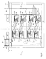
- Fig. 1 shows an example as a tower, in particular designed as an eight-tower, z. B. in a frame 24 enclosed printing unit 01 a preferably used for colored newspaper printing rotary printing machine, wherein the printing unit 01 is designed in a very compact design, ie in particular with a low overall height.
- a pressure unit 01 designed as a 16-tower two such four-high towers can also be arranged.
- As a paper web 02 is preferably guided substantially vertically through the printing unit 01.
- each printing unit 03 is also equipped with a plurality of rollers preferably zoneless inking unit 07, z. B. with an anilox roller having a short inking unit 07, wherein the rollers of the inking 07 formed from a color reservoir ink to form a thin ink film and this color film in its layer thickness uniform and transport to each forme cylinder 06 order order on at least one arranged on the forme 06 printing form.
- the respective forme cylinder 06 of each printing unit 03 has an axial length in the range z. B.
- the in the Fig. 1 Rotary printing machine illustrated by way of example preferably prints in a dry offset printing process, ie in an offset process without using a dampening solution, which is why the in the Fig. 1 illustrated printing units 03 each have no dampening unit.
- each of the printing units 03 of the printing unit 01 has in each case a printing forme magazine 08, wherein the respective printing forme magazine 08 is in each case associated with the forme cylinder 06 of the respective printing unit 03.
- Each printing forme magazine 08 has at least one storage position for storing at least one printing form, wherein the respective storage position can be preferably realized in each case in a shaft or through a shaft, said shaft preferably a z.
- Each printing forme magazine 08 preferably also has one Shaft with a likewise preferably remote-controlled conveyor for discharging at least one used printing forme from the forme cylinder 06.
- each slot of the printing forme magazine 08 each has a plurality of storage positions for receiving a plurality of the forme cylinder 06 to be fed pressure forms and / or in the respective printing forme magazine 08 also several storage positions for the forme cylinder 06 discharged Printing forms are provided.
- the printing forms to be recorded at several storage positions of the respective shaft, d. H. the new or used printing plates can be stored in the respective slot each in a batch process, wherein the respective forme cylinder 06 z. B. fed sequentially or be discharged sequentially from this forme cylinder 06.
- the respective printing forme magazines 08 may be fixedly mounted in the printing unit 01 fixed or they are by a preferably remotely controllable movement, for. B. brought by a pivoting movement from a rest position into a working position with that forme cylinder 06, to which they are respectively assigned, if necessary, in an operative connection to perform the process of supplying or discharging of at least one printing plate.
- the operative connection between the printing forme magazine 08 and the associated forme cylinder 06 can, for. B. be prepared by the fact that the respective printing forme magazine 08 with its longitudinal extent ( Fig. 1 and 2 ) is preferably made tangential to the respective forme cylinder 06, wherein the longitudinal extent of the respective printing forme magazine 08 preferably substantially horizontally, ie with a tolerance of z. B.
- the operative connection between the printing forme magazine 08 and the associated forme cylinder 06 is z. B. thereby repealed that the respective printing forme magazine 08 is turned off by the respective forme cylinder 06 such that the change of a printing form from the printing forme magazine 08 to the respective forme cylinder 06 z. B. is not executable because of too large a distance between the printing forme magazine 08 and the respective forme cylinder 06 or an inappropriate alignment between them.
- the operative connection between the printing forme magazine 08 and the forme cylinder 06 assigned to it there is either a touch contact or a mouth region of the printing forme magazine 08 located at a distance of only a few millimeters from the lateral surface of the relevant forme cylinder 06.
- the operative connection between the printing forme magazine 08 and the associated forme cylinder 06 can, for. B. also be prepared or repealed that a control unit releases the respective printing forme magazine 08 in its related to the change of a printing form function or locks, wherein the respective printing forme magazine 08 preferably not changed in its spatial arrangement to the respective forme cylinder 06.
- the respective printing forme magazines 08 have z. B. at its side facing away from the forme cylinder 06, that is, at the opposite end of its mouth region in each case at least one z. B. slot-shaped opening through which at least one new printing form their respective storage position in the printing forme magazine 08 can be fed, wherein at a slot-shaped opening whose parallel to the axial direction of the forme 06 extending slot width a multiple, z. B. is at least threefold of their orthogonal slot height.
- slot-shaped opening ie the width of this side of the printing plate and at least extending in the axial direction of the forme 06 extension of the opening of the printing forme magazine 08 are in their spatial arrangement, ie in their respective Position and orientation adapted to each other and thereby rectified.
- the corresponding slot z. B. also removed at least one used printing form.
- the respective printing forme magazine 08 can have a corresponding number of memory positions arranged next to one another.
- a plurality of printing forme magazines 08 of the type described above are arranged next to one another in the case of a plurality of pressure molds arranged side by side in the axial direction of the respective forme cylinder 06 in the axial direction of the respective forme 06.
- a plurality of pressure molds arranged side by side in the axial direction of the respective forme cylinder 06 in the axial direction of the respective forme 06.
- 6/2-forme cylinders 06 each equipped with printing plates, one in its axial direction at six juxtaposed mounting locations and in its circumferential direction at two consecutively arranged mounting locations each with a printing plate assignable forme cylinder 06 as 6/2-forme cylinder 06 is designated.
- a printing unit 01 printing on both sides of the printing material 02 with four printing inks is referred to as a 4/4 printing unit.
- the printing plates are each arranged by means of a respective form cylinder 06 preferably arranged remotely operable holding device, for. B. a clamping device, attached to the respective form cylinder 06.
- the holding device is z. B. pneumatically actuated and arranged in a channel of the respective forme cylinder 06, wherein this channel extends in the axial direction of the respective forme cylinder 06.
- the handling device 09 is designed as a controlled, automatically reacting movement device, ie as a controlled, preferably program-controlled automaton 09, the handling device 09 arranged on the same operating side of the printing unit 01 in different levels Druckformmagazine 08 in an automated sequence each with the at least one Fed printing form.
- the handling device 09 by its controlled movement on the same operating side of the printing unit 01 arranged in different levels Druckformmagazines 08 each at least one of her gripped, ie held printing form a particular storage position of the respective printing forme magazine 08 pinpoint, the handling device 09 preferably each printing plate each with their regarding the production direction of them receiving mold cylinder 06 leading end of the respective printing forme magazine 08 feeds.
- the handling device 09 thus preferably guides each printing plate in each case with its leading end with respect to the direction of production of the female cylinder 06 receiving end through the opening of the respective printing forme magazine 08 in the storage position provided in this printing forme magazine 08.
- the handling device 09 is positioned on or in front of the corresponding operating side of the printing unit 01.
- Each operating side of the printing unit 01 comprises at least the working area or handling area of the operating personnel on this printing unit 01, the operating side Operating personnel access to the respective form cylinders 06 and printing forme magazines 08 allows to perform work on the forme 06 and printing forme magazines 08.
- the respective handling device 09 feeds z. B. several arranged on the same operating side of the printing unit 01 in different preferably horizontally extending planes of this printing unit 01 Druckformmagazine 08 simultaneously with at least one new printing plate. Additionally or alternatively it can be provided that with the respective handling device 09 more, preferably all storage positions of the same forme cylinder 06 associated printing plate magazine 08 are each loaded simultaneously with a new printing plate and are loaded accordingly, so z. B. on a 6/2-form cylinder several, preferably all of the twelve mounting locations corresponding memory positions of this form cylinder 06 associated printing forme magazine 08 are each loaded simultaneously with a new printing form.
- the handling device 09 is preferably only temporarily present on or in front of the relevant operating side of the printing unit 01, namely only for carrying out the charging process or for discharging printing forms that are no longer required.
- the handling device 09 preferably has in each case one at least one printing form vertically transporting lifting device, each of the printing forms to be transported is preferably transported in each case with an at least vertically movable platform 11 to that preferably horizontal plane on which the printing forme magazine 08 to be loaded at least with its at least is located a new printing form receiving storage position.
- the movable at least one printing plate movable platform 11 is guided in its vertical movement, preferably based on z. B. laterally on the platform 11 arranged rails 12, z. B. of at least two rails 12 which are arranged parallel to each other, extend vertically and are preferably mounted in each case in or on the frame 24 of the printing unit 01 stationary.
- a lifting means for carrying out the lifting movement of the at least one platform 11 of the lifting device can, for. B. at least one chain, a toothed belt, a belt or a spindle gear can be provided, wherein the lifting means is preferably formed as at least one pair of the aforementioned means.
- a platform 11 assigned to a specific assembly site on one of the forme cylinders 06 can receive and transport several, in particular two, printing forms, these printing forms being moved vertically by the same platform 11 preferably being provided for mounting on the same forme cylinder 06 in its circumferential direction, wherein printing forms conveyed by the same platform 11 are transferred sequentially or simultaneously to the printing forme magazine 08 assigned to the forme cylinder 06 for feeding its storage positions.
- Several printing forms stored in the same printing forme magazine 08 at different storage positions, which are provided for mounting at the same axial position of the forme magazine 08 assigned to this printing forme magazine 08, are fed sequentially to this forme cylinder 06 from the respective storage position of the printing forme magazine 08 and thus also sequentially in the circumferential direction of the relevant forme cylinder 06 mounted.
- a handling device 09 is provided on both operating sides of the printing unit 01, the printing unit 01 having on each of its operating sides a plurality of printing units 03, each arranged in different preferably horizontal planes, wherein in each of these planes at least one printing forme magazine to be charged in each case with at least one printing forme 08 is provided.
- Each of these handling devices 09 can each have at least one movable platform 11 guided in its vertical movement, preferably several of these platforms 11.
- an electric motor or a pneumatic drive is preferably remotely operable.
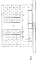
- the at least one printing plate transporting platforms 11 of the same handling device 09 are stacked in the respective handling device 09 and can either only in their entirety, ie in a rigid composite as a package ( Fig. 1 ) or in a stacking manner individually ( Fig. 2 ), in the case of their mobility in a rigid composite, the at least one to be loaded printing forme magazine 08 having horizontal levels one after the other, ie sequentially approached by the drive simultaneously moving platforms 11 and wherein in the case of their individual mobility these platforms 11 are sequentially moved and each of these platforms 11 of the respective handling device 09 is associated with exactly a single specific horizontal plane, in such a way that z. B.
- the respective platforms 11 of the respective handling device 09 After an executed change of at least one printing plate at a arranged in the respective horizontal plane of the printing unit 01 printing forme magazine 08, the respective platforms 11 of the respective handling device 09 from the respective drive back to their original position in a range z. B. driven above the printing unit 01, where the respective platforms 11 are stacked again stacked in the form of an assembled package.
- the starting position for the lifting movement of the platforms 11 of the handling device 09 in an area above the printing unit 01 can also be provided that the starting position for the lifting movement of the platforms 11 of the handling device 09 below z. B.
- a memory 13 which is also vertically movable by the handling device 09 can be provided for receiving used printing forms, this memory 13 receiving printing forms taken from the respective forme cylinders 06 and stored in the associated respective printing form magazines 08 and these from the printing units 03 of the printing unit 01 transported away.
- the used printing form receiving memory 13 is preferably formed as a collecting memory 13, because for used printing plates in terms of their inclusion in the memory 13, the observance and compliance with a particular order is not required.
- the used printing plates from all preferably horizontal planes of the printing unit 01 receiving accumulator 13 is in the handling device 09 z. B. arranged below the bottom platform 11.
- the Fig. 1 and 2 differ only in the mobility of the platforms 11 the same handling device 09.
- the handling device 09, the conveyors of the respective printing forme magazines 08 and preferably also the respective holding devices of the forme cylinder 06 are z. B. from one of the printing unit 01 associated (not shown) control unit or operating unit, for. B. controllable from a control station of the rotary printing press or operable.
- Fig. 3 shows schematically in a simplified representation, the printing unit 01 of Fig. 1 or 2 in a plan view, this printing unit 01 is integrated into a transport system for her to be supplied or discharged from her printing forms.
- An imaged in an (not shown) imaging system, ie provided with a subject printing plate is in preparation for their subsequent attachment to one of the printing unit 01 associated with the forme cylinder 06 preferably at two of its opposite ends z.
- B. rail-mounted preferably remotely controllable conveyor 14 of the transport system transported to the printing unit 01, wherein the transport of the printing form is preferably horizontal, that is, in its lying state.
- the printing plates required in the printing unit 01 are transported in this way with the conveyor 14 of the transport system sequentially to the printing unit 01.
- the transport system can have at least one buffer, in which imprinted in the imaging system printing forms can be stored until their transport to the printing unit 01.
- imaged printing forms belonging to a plurality of different editions can be stored until the production of the respective edition on the printing unit 01 is pending for execution.
- the use of a buffer eliminates the need to transport imaged printing plates in each case directly from the imaging system to the printing unit 01.
- Each of the printing forms to be transported to the printing unit 01 with the conveying device 14 of the transport system is preferably each provided with a coding (not shown) so that it is addressed and assigned unambiguously to a specific installation location in the printing unit 01.
- a code reader detects the encoding of the printing form and an identification system (not shown) using this code reader has identified a printing unit transported to the printing unit 01 as belonging to this printing unit 01
- the printing form conveyed by the conveying device 14 becomes the area of the printing unit 01 taken over there and of a transport device depending on their addressing automatically to one of the operating pages of the printing unit 01, ie the right or left side of the operating in the Fig. 3 shown in its plan view printing unit 01.
- each of these printing plates has a respective leading end in its direction of production and a trailing end in its direction of production. Since each printing plate is to be supplied with its leading end a printing forme magazine 08 and then their respective forme cylinder 06, which transported with the conveyor 14 of the transport system to the printing unit 01 transported printing form on its transport to one of the two operating sides of the printing unit 01 to a perpendicular to the Working surface of the printing plate standing axis are turned by 180 °, which is arranged with a transport path in the printing forme, z. B. as a turntable 16 formed turning device 16 is done.
- Parallel to the axial direction of the forme cylinder 06 are preferably on both sides of the printing unit 01 preferably in a region outside of the respective operating side of the printing unit 01 working area of the operator of the rotary printing machine a distributor 17 for distributing the printing unit 01 transported printing forms on the printing units 03 this Pressure unit 01 is provided, wherein the distribution device 17 on each of the two operating sides of the printing unit 01 each transported to the printing unit 01 printing form according to their respective addressing in each case an axial mounting positions with respect to this printing form later receiving cylinder 06 assigns, the distribution device 17 in the axial direction of the respective forme cylinder 06th as many subjects 18 has arranged side by side, as are provided with respect to these forme cylinder 06 axial mounting positions, these subjects 18 successively with the Förd Be filled 14 brought-in printing forms.
- each printing form held in one of the compartments 18 is preferably transferred under program control to a platform 11 of the handling device 09 corresponding to the axial mounting position.
- all printing forms held in the respective compartments 18 by one of the distributing devices 17 are simultaneously transferred to the platforms 11 of the handling device 09 corresponding to the respective axial assembly position.
- the transfer of the in the respective compartments 18 held by one of the distributing devices 17 printing forms to the respective with respect to the axial mounting position corresponding platforms 11 of the handling device 09 may, for. B. by the use of one or more of the respective distribution device 17 from acting, preferably remotely operated slide. Since the transfer of the in the respective compartments 18 of one of the distribution devices 17 reproached printing forms to the respective axial mounting position corresponding platforms 11 of the handling device 09 regardless of the operation of the printing units 03 this printing unit 01 takes place, this transfer can be carried out readily during an ongoing production of rotary printing machine.
- the transfer of the held in the respective compartments 18 of one of the distributing devices 17 printing forms to the respective with respect to the axial mounting position corresponding platforms 11 of the handling device 09 is z. B. during an ongoing production of the printing unit 01.
- the respective transport direction of the printing plates is in the Fig. 3 each indicated by directional arrows.
- the change of at least one held in one of the platforms 11 of the handling device 09 printing forms with one of the printing forme magazines 08 of the printing unit 01 can be carried out automatically during the current production of the rotary printing press, without manual intervention of the rotary press operating operator is required. In the same way, but with opposite direction of movement can be removed in the printing unit 01 no longer used printing plates using the respective handling device 09 and distributor 17 from the printing unit 01 and finally transported away with the conveyor 14 of the transport system.
- Access to the printing units 03 of the printing unit 01 is to be shut off only for the period against the access of operating personnel using this rotary printing press, in which the respective handling device 09 positions at least one of their respective platforms 11 in the horizontal plane of one of the printing forme magazines 08 of this printing unit 01, wherein this period may be very short due to a preferably fully automated sequence of the change of at least one printing plate between the platform 11 of the handling device 09 and the respective printing forme magazine 08 and z. B. may be in the lower single-digit minute range.
- the respective Handling device 09 also all on their respective platforms 11 stored printing forms with the respective corresponding printing forme magazines 08 can exchange simultaneously, this parallel loading process of the printing forme magazines 08 understandably less time than a sequential, machine or manually running feeding the printing forme magazines 08.
- the respective Handling devices 09 are brought on both sides of the printing unit 01 simultaneously used, which further accelerates the process of loading the printing forme magazines 08 of this printing unit 01.
- a memory 19 acting as a waste storage 19 for receiving at least one printing forme provided this memory 19 also like the belonging to the same handling device 09 distribution device 17 in the axial direction of the respective forme cylinder 06 preferably a plurality of juxtaposed Compartment 21 has.
- the memory 19 serves to receive at least one printing forme, which is replaced with respect to an axial mounting position of at least one forme cylinder 06 by another, more recent, provided for this mounting position printing form.
- the printing form serving for the update is preferably transported to the printing unit 01 by the conveying device 14 of the transport system, as well as the other printing forms to be mounted on at least one of the forme cylinders 06 of this printing unit 01, and then fed to the respective handling device 09 via the distributor device 17.
- a printing form serving for updating is preferably transported with a high priority, ie primarily to the respective handling device 09 and then further to the respective printing forme magazine 08, where it is recorded in the printing process.
Landscapes
- Rotary Presses (AREA)
- Printers Characterized By Their Purpose (AREA)
- Inking, Control Or Cleaning Of Printing Machines (AREA)
- Ultra Sonic Daignosis Equipment (AREA)
Claims (56)
- Unité d'impression (01) d'une machine à imprimer rotative, avec au moins deux cylindres de forme (06), ces cylindres de forme étant disposés dans différents plans, du même côté de desserte de l'unité d'impression (01), et étant susceptibles d'être chacune garnie d'au moins une forme d'impression, un magasin à formes d'impression (08) avec plusieurs positions de stockage étant chaque fois associé aux au moins deux cylindres de forme (06), dans chacun de ces magasins à formes d'impression (08) étant susceptible d'être stockée chaque fois au moins une forme d'impression, pouvant être changée entre le magasin à formes d'impression (08) concerné et le cylindre de forme (06) associé, caractérisée en ce que, sur le côté de desserte concerné de l'unité d'impression (01) est prévu un dispositif de manutention (09) commandé, à l'aide duquel les magasins à formes d'impression (08) disposés dans différents plans, du même côté de desserte de l'unité d'impression (01), sont simultanément susceptibles d'être chargés avec au moins une forme d'impression, le dispositif de manutention (09), au moyen de son déplacement commandé, amenant chaque fois la au moins une forme d'impression d'une position de stockage déterminée du magasin à formes d'impression (08) respectif aux magasins à formes d'impression (08) disposés dans différents plans, du même côté de desserte de l'unité d'impression (01), les positions de stockage du magasin à formes d'impression (08) correspondant à des emplacements de montage sur le cylindre de forme (06) associé à ce magasin à formes d'impression (08), le dispositif de manutention (09) introduisant chaque forme d'impression, chaque fois par son extrémité avant, du point de vue du sens de production du cylindre de forme (06) la recevant, dans la position de stockage prévue du magasin à formes d'impression (08) concerné.
- Unité d'impression (01) selon la revendication 1, caractérisée en ce que le dispositif de manutention (09) n'est présent au côté de desserte concerné de l'unité d'impression (01) que pour accomplir le processus de chargement ou pour procéder à l'évacuation d'au moins une forme d'impression qui n'est plus nécessaire.
- Unité d'impression (01) selon la revendication 1, caractérisée en ce que le dispositif de manutention (09) est réalisé sous forme d'appareil automatique.
- Unité d'impression (01) selon la revendication 1, caractérisée en ce que le dispositif de manutention (09) charge chaque fois avec la au moins une forme d'impression les magasins à formes d'impression (08) disposés dans différents plans, du même côté de desserte de l'unité d'impression (01), en suivant un déroulement opératoire automatisé.
- Unité d'impression (01) selon la revendication 1, caractérisée en ce que les plans, dans lesquels les cylindres de forme (06) et/ou les magasins à formes d'impression (08) leur étant associés sont chaque fois disposés du même côté de desserte de l'unité d'impression (01), s'étendant chacun horizontalement.
- Unité d'impression (01) selon la revendication 1, caractérisée en ce que le dispositif de manutention (09), positionné sur ou devant le côté de desserte de l'unité d'impression (01), effectue un mouvement vertical.
- Unité d'impression (01) selon la revendication 1, caractérisée en ce que le dispositif de manutention (09) présente un dispositif de levage transportant verticalement au moins une forme d'impression.
- Unité d'impression (01) selon la revendication 1, caractérisée en ce que le dispositif de manutention (09) amène chaque forme d'impression au magasin à formes d'impression (08) concerné, chaque fois avec son extrémité avant, du point de vue du sens de production du cylindre de forme (06) la recevant.
- Unité d'impression (01) selon la revendication 1, caractérisée en ce que le dispositif de manutention (09) transporte chacune des formes d'impression à transporter, chaque fois avec une plateforme (11) mobile au moins verticalement, au plant dans lequel le magasin à formes d'impression (08) doit être garni de la forme d'impression transportée.
- Unité d'impression (01) selon la revendication 9, caractérisée en ce que le dispositif de manutention (09) positionne la plateforme (11) dans le plan d'un des magasins à formes d'impression (08) de cette unité d'impression (01).
- Unité d'impression (01) selon la revendication 9, caractérisée en ce que la plateforme (11) transportant la au moins une forme d'impression est guidée dans son mouvement vertical.
- Unité d'impression (01) selon la revendication 9, caractérisée en ce que plusieurs plateformes (11), transportant chacune au moins une forme d'impression, sont prévues dans le dispositif de manutention (09).
- Unité d'impression (01) selon la revendication 12, caractérisée en ce que la pluralité de plateformes (11), transportant chacune au moins une forme d'impression, sont disposées en empilement les unes au-dessus des autres dans le dispositif de manutention (09).
- Unité d'impression (01) selon la revendication 9, caractérisée en ce que, pour chaque plan, qui présente au moins un magasin à formes d'impression (08) à garnir d'au moins une forme d'impression, est prévu chaque fois une plateforme (11) mobile.
- Unité d'impression (01) selon la revendication 9, caractérisée en ce qu'au moins une chaîne, une courroie dentée, une bande ou une transmission à vis est prévue en tant que moyen de levage pour accomplir le mouvement de levage de la au moins une plateforme (11) du dispositif de levage.
- Unité d'impression (01) selon la revendication 9, caractérisée en ce qu'un entraînement, pour le déplacement de la au moins une plateforme (11) du dispositif de manutention (09), est susceptible d'être télécommandé.
- Unité d'impression (01) selon la revendication 12, caractérisée en ce que les plateformes (11), transportant chacune au moins une forme d'impression, du dispositif de manutention (09) ne sont déplaçables en un ensemble rigide que dans leur totalité.
- Unité d'impression (01) selon la revendication 17, caractérisée en ce que les plateformes (11), déplacées en un ensemble rigide, approchent séquentiellement les plans, présentant chaque fois au moins un magasin à formes d'impression (08) devant être garni, de l'unité d'impression (10).
- Unité d'impression (01) selon la revendication 12, caractérisée en ce que les plateformes (11), transportant chacune au moins une forme d'impression, du dispositif de manutention (09) sont déplaçables individuellement.
- Unité d'impression (01) selon la revendication 19, caractérisée en ce que les plateformes (11) déplacées individuellement sont chacune précisément associées à un plan déterminé unique.
- Unité d'impression (01) selon la revendication 20, caractérisée en ce que les plateformes (11) déplacées individuellement passent chacune simultanément en une liaison fonctionnelle avec les magasins à formes d'impression (08) devant chacun être garni d'au moins une forme d'impression, leur étant associés dans les différents plans.
- Unité d'impression (01) selon la revendication 20, caractérisée en ce que la plateforme (11), disposée à la position la plus basse dans le dispositif de manutention (09), arrive au plan le plus bas et la plateforme (11), disposée à la position la plus haute dans le dispositif de manutention (09), arrive au plan le plus haut, et les plateformes (11), disposées entre celle située le plus bas et celle située le plus haut, dans le dispositif de manutention (09) arrivent aux plans, leur correspondant, de cette unité d'impression (01).
- Unité d'impression (01) selon la revendication 9, caractérisée en ce que le dispositif de manutention (09) déplace sa au moins une plateforme (11), d'une zone située à l'extérieur d'une zone de travail se trouvant du côté de desserte de l'unité d'impression (01), du personnel opérateur de la machine à imprimer rotative, aux plans respectifs de cette unité d'impression (01).
- Unité d'impression (01) selon la revendication 12, caractérisée en ce que le dispositif de manutention (09), chaque fois après avoir opéré le changement d'au moins une forme d'impression avec un magasin à formes d'impression (08) disposé dans le plan respectif, ramène chacune de ses plateformes (11) à sa position initiale, dans la zone située à l'extérieur de la zone de travail se trouvant du côté de desserte de l'unité d'impression (01), du personnel opérateur de la machine à imprimer rotative.
- Unité d'impression (01) selon la revendication 9, caractérisée en ce qu'une plate forme (11), associée à un emplacement de montage déterminé, fixé par l'un des cylindres de forme (06) dans sa direction axiale, transporte simultanément plusieurs formes d'impression.
- Unité d'impression (01) selon la revendication 25, caractérisée en ce que les formes d'impression, déplacées verticalement par la même plateforme (11), sont prévues pour le montage sur le même cylindre de forme (06) dans sa direction périphérique.
- Unité d'impression (01) selon la revendication 25, caractérisée en ce que le dispositif de manutention (09) transfère des formes d'impression, transportées par la même plateforme (11), séquentiellement ou simultanément, aux positions de stockage du magasin à formes d'impression (08) associé au cylindre de forme (06) respectif.
- Unité d'impression (01) selon la revendication 1, caractérisée en ce que le magasin à formes d'impression (08) respectif amène des formes d'impression, stockées en lui à différentes positions de stockage, prévues pour montage à la même position axiale du cylindre de forme (06) associé à ce magasin à formes d'impression (08), séquentiellement, à partir des positions de stockage respectives, à son cylindre de forme (06) chaque fois associé.
- Unité d'impression (01) selon la revendication 1, caractérisée en ce que le dispositif de manutention (09) présente un accumulateur (13), pour recevoir des formes d'impression qui ne sont plus nécessaires aux cylindres de forme (06).
- Unité d'impression (01) selon la revendication 29, caractérisée en ce que l'accumulateur (13) est déplaçable verticalement par le dispositif de manutention (09).
- Unité d'impression (01) selon la revendication 29, caractérisée en ce que l'accumulateur (13) reçoit des formes d'impression, prélevées des cylindres de forme (06) respectifs et déposés dans les magasins à formes d'impression (08) respectifs afférents, et procède à un transport d'évacuation de ces formes d'impression à l'écart des groupes d'impression (03) de l'unité d'impression (01).
- Unité d'impression (01) selon la revendication 29, caractérisée en ce que l'accumulateur (13) est réalisé sous forme d'accumulateur collecteur (13).
- Unité d'impression (01) selon la revendication 29, caractérisée en ce que l'accumulateur (13) est disposé au-dessous de la position la plus basse du dispositif de manutention (09).
- Unité d'impression (01) selon la revendication 1, caractérisée en ce que chaque forme d'impression, transportée à l'unité d'impression (01) avec un dispositif de transport (14) d'un système de transport, est chaque fois munie d'un codage, pour son affectation univoque à un emplacement de montage déterminé dans l'unité d'impression (01).
- Unité d'impression (01) selon la revendication 34, caractérisée en ce qu'un système d'identification appréhende, avec un lecteur de code, le codage respectif de chaque forme d'impression transportée à l'unité d'impression (01).
- Unité d'impression (01) selon la revendication 34, caractérisée en ce qu'un dispositif de transport prend en charge une forme d'impression, identifiée par le système d'identification comme appartenant à l'unité d'impression (01), par le dispositif de transport (14) du système de transport, et amène cette forme d'impression, de manière correspondante à son adressage, au côté de desserte respectif de l'unité d'impression (01).
- Unité d'impression (01) selon la revendication 36, caractérisée en ce que le dispositif de transport, aux deux côtés de desserte de l'unité d'impression (01), amène à un magasin à formes d'impression (08) chaque forme d'impression, chaque fois par son extrémité avant, du point de vue du sens de production du cylindre de forme (06) la recevant.
- Unité d'impression (01) selon la revendication 36, caractérisée en ce que le dispositif de transport présente au moins un dispositif de retournement (16), le dispositif de retournement retournant de 180° autour d'un axe vertical situé sur la surface de travail de la forme d'impression, une forme d'impression sur son chemin de transport à l'un des deux côtés de desserte de l'unité d'impression (01).
- Unité d'impression (01) selon la revendication 1, caractérisée en ce qu'un dispositif répartiteur (17), pour répartir sur les groupes d'impression (03), sur ce côté de desserte de l'unité d'impression (01), les formes d'impression transportées à un côté de desserte de l'unité d'impression (01), est prévu, parallèlement à la direction axiale des cylindres de forme (06).
- Unité d'impression (01) selon la revendication 39, caractérisée en ce que chaque fois un dispositif répartiteur (17) est prévu sur les deux côtés de desserte de l'unité d'impression (01), parallèlement à la direction axiale des cylindres de forme (06).
- Unité d'impression (01) selon la revendication 39, caractérisée en ce que le dispositif répartiteur (17) est disposé dans une zone située à l'extérieur de la zone de travail, se trouvant du côté de desserte de l'unité d'impression (01), du personnel opérateur de la machine à imprimer rotative.
- Unité d'impression (01) selon la revendication 39, caractérisée en ce que le dispositif répartiteur (17) affecte chaque forme d'impression, transportée à l'unité d'impression (01), selon son adressage respectif, chaque fois à l'une des positions de montage axiale, eu égard au cylindre de forme (06) recevant ultérieurement cette forme d'impression.
- Unité d'impression (01) selon la revendication 39, caractérisée en ce que le dispositif répartiteur (17) présente, en direction axiale des cylindre de forme (06) respectifs, des compartiments (18), disposés les uns à côté des autres, en nombre égal au nombre de positions de montage axiales prévues, eu égard à ces cylindres de forme (06).
- Unité d'impression (01) selon la revendication 39, caractérisée en ce que le dispositif répartiteur (17) transfère chaque forme d'impression, stockée dans l'un de ses compartiments (18), à une plateforme (11) du dispositif de manutention (09).
- Unité d'impression (01) selon la revendication 44, caractérisée en ce que la plateforme (11) du dispositif de manutention (09), à laquelle le dispositif répartiteur (17) transfère une forme d'impression stockée dans l'un de ses compartiments (18), correspond à la position de montage axiale de cette forme d'impression sur le cylindre de forme (06) concerné.
- Unité d'impression (01) selon la revendication 39, caractérisée en ce que le dispositif répartiteur (17) transfère simultanément toutes les formes d'impression stockées dans ses compartiments (18) aux plateformes (11) du dispositif de manutention (09).
- Unité d'impression (01) selon la revendication 1 ou 39, caractérisée en ce qu'un accumulateur (19) est prévu pour recevoir au moins une forme d'impression, cet accumulateur recevant une forme d'impression, à remplacer par une forme d'impression plus actuelle, stockée dans le dispositif de manutention (09) ou dans le dispositif répartiteur (17), pour une position de montage déterminée sur l'un des cylindres de forme (06).
- Unité d'impression (01) selon la revendication 47, caractérisée en ce que l'accumulateur (19) est disposé dans la zone située à l'extérieur de la zone de travail, se trouvant du côté desserte de l'unité d'impression (01), du personnel opérateur de la machine à imprimer rotative.
- Unité d'impression (01) selon la revendication 47, caractérisée en ce que l'accumulateur (19) présente plusieurs compartiments (21), disposés les uns à côté des autres, dans la direction axiale des cylindres de forme (06).
- Unité d'impression (01) selon la revendication 1, caractérisée en ce que les magasins à formes d'impression (08) respectifs sont accostés, avec leur étendue longitudinale, tangentiellement au cylindre de forme (06) respectif.
- Unité d'impression (01) selon la revendication 50, caractérisée en ce que l'étendue longitudinale du magasin à formes d'impression (08) respectif est orientée sensiblement horizontalement.
- Unité d'impression (01) selon la revendication 1, caractérisée en ce que les magasins à formes d'impression (08) présentent chacun, sur leur face frontale opposée au cylindre de forme (06), au moins une ouverture, à travers laquelle la au moins une nouvelle forme d'impression peut être amenée à sa position de stockage respective, dans le du magasin à formes d'impression (08) respectif.
- Unité d'impression (01) selon la revendication 52, caractérisée en ce que l'ouverture du magasin à formes d'impression (08) respectif est chaque fois réalisée en forme de fente.
- Unité d'impression (01) selon la revendication 52, caractérisée en ce que l'ouverture du magasin à formes d'impression (08) respectif s'étend chaque fois dans la direction axiale du cylindre de forme (06).
- Unité d'impression (01) selon la revendication 52, caractérisée en ce que la largeur du côté de chaque forme d'impression à introduire dans le magasin à formes d'impression (08) respectif, et l'étendue, s'étendant dans la direction axiale du cylindre de forme (06), du magasin à formes d'impression (08) sont mutuellement adaptées, quant à leur position et orientation respectives.
- Unité d'impression (01) selon la revendication 1, caractérisée en ce qu'une unité de commande déclenche ou bloque le magasin à formes d'impression (08) respectif, dans sa fonction concernant le changement d'une forme d'impression avec le cylindre de frome (06) associé.
Applications Claiming Priority (1)
| Application Number | Priority Date | Filing Date | Title |
|---|---|---|---|
| DE102006032200A DE102006032200A1 (de) | 2006-07-12 | 2006-07-12 | Druckeinheit einer Rotationsdruckmaschine |
Publications (3)
| Publication Number | Publication Date |
|---|---|
| EP1878570A2 EP1878570A2 (fr) | 2008-01-16 |
| EP1878570A3 EP1878570A3 (fr) | 2008-07-30 |
| EP1878570B1 true EP1878570B1 (fr) | 2011-05-04 |
Family
ID=38617950
Family Applications (1)
| Application Number | Title | Priority Date | Filing Date |
|---|---|---|---|
| EP07110278A Not-in-force EP1878570B1 (fr) | 2006-07-12 | 2007-06-14 | Unité d'impression d'une presse rotative |
Country Status (3)
| Country | Link |
|---|---|
| EP (1) | EP1878570B1 (fr) |
| AT (1) | ATE507971T1 (fr) |
| DE (2) | DE102006032200A1 (fr) |
Families Citing this family (10)
| Publication number | Priority date | Publication date | Assignee | Title |
|---|---|---|---|---|
| DE102008036053A1 (de) * | 2008-08-01 | 2010-02-04 | Manroland Ag | Rollenrotationsdruckmaschine |
| DE102009045402B4 (de) | 2009-01-20 | 2020-04-16 | Koenig & Bauer Ag | Druckformmagazin einer Druckeinheit |
| EP2346690B1 (fr) * | 2008-10-24 | 2012-09-12 | Koenig & Bauer AG | Procédé pour mettre à disposition des formes imprimantes sur des positions de montage sur l'un de plusieurs cylindres porte-clichés disposés dans une machine à imprimer |
| DE102008043160A1 (de) | 2008-10-24 | 2010-04-29 | Koenig & Bauer Aktiengesellschaft | Verfahren zum Wechseln von in einer Druckmaschine verwendeten Druckformen |
| DE102009000217B4 (de) | 2009-01-14 | 2013-01-10 | Koenig & Bauer Aktiengesellschaft | Verfahren zum Wechseln von in einer Druckmaschine verwendeten Druckformen |
| DE102009052144A1 (de) * | 2008-11-21 | 2010-05-27 | Heidelberger Druckmaschinen Ag | Transportvorrichtung für Druckplatten |
| DE102008044227B4 (de) * | 2008-12-01 | 2011-02-03 | Koenig & Bauer Aktiengesellschaft | Verfahren und Vorrichtung zur Übergabe mindestens einer Druckform von einer ersten Speichereinrichtung an eine zweite Speichereinrichtung |
| US8322283B2 (en) | 2009-01-14 | 2012-12-04 | Koenig & Bauer Aktiengesellschaft | Method for providing printing formes at installation positions on one of a plurality of forme cylinders disposed in a printing press |
| US8316767B2 (en) | 2009-01-20 | 2012-11-27 | Koenig & Bauer Aktiengesellschaft | Transport system for providing printing formes to a printing unit |
| DE102009039050A1 (de) * | 2009-08-28 | 2011-03-10 | Manroland Ag | Rollenrotationsdruckmaschine |
Family Cites Families (7)
| Publication number | Priority date | Publication date | Assignee | Title |
|---|---|---|---|---|
| JPS6262762A (ja) * | 1985-09-12 | 1987-03-19 | Tokyo Kikai Seisakusho:Kk | 新聞印刷における生産工程管理方式 |
| US4727807A (en) * | 1985-09-30 | 1988-03-01 | Tokyo Kikai Seisakusho | Apparatus for automatically mounting and removing printing plates in rotary printing press |
| JP2724668B2 (ja) * | 1993-09-24 | 1998-03-09 | 株式会社東京機械製作所 | 刷版配送装置 |
| JP3592760B2 (ja) * | 1994-10-12 | 2004-11-24 | 株式会社小森コーポレーション | 輪転印刷機の自動版替方法およびその装置 |
| DE4442265A1 (de) * | 1994-11-28 | 1996-05-30 | Roland Man Druckmasch | Transportsystem zum Transport von Druckformen |
| EP0823663A1 (fr) * | 1996-08-07 | 1998-02-11 | Bayer Corporation | Procédé et appareil pour un traiteur automatique de plaques ayant un ascenseur et un mécanisme de table-support |
| GB2413530A (en) * | 2004-04-29 | 2005-11-02 | Goss Graphic Systems Ltd | Printing plate module and printing press |
-
2006
- 2006-07-12 DE DE102006032200A patent/DE102006032200A1/de not_active Withdrawn
-
2007
- 2007-06-14 DE DE502007007102T patent/DE502007007102D1/de active Active
- 2007-06-14 AT AT07110278T patent/ATE507971T1/de active
- 2007-06-14 EP EP07110278A patent/EP1878570B1/fr not_active Not-in-force
Also Published As
| Publication number | Publication date |
|---|---|
| DE502007007102D1 (de) | 2011-06-16 |
| EP1878570A2 (fr) | 2008-01-16 |
| DE102006032200A1 (de) | 2008-01-17 |
| ATE507971T1 (de) | 2011-05-15 |
| EP1878570A3 (fr) | 2008-07-30 |
Similar Documents
| Publication | Publication Date | Title |
|---|---|---|
| EP1878570B1 (fr) | Unité d'impression d'une presse rotative | |
| DE102006032204B3 (de) | Verfahren zur Bereitstellung mindestens einer Druckform an ihrem Montageort auf einem Formzylinder einer Rotationsdruckmaschine | |
| EP2028007B1 (fr) | Unité d'impression comprenant plusieurs groupe d'impression | |
| EP1878571B1 (fr) | Unité d'impression d'une presse rotative | |
| DE102008044228B4 (de) | Druckeinheit mit mindestens einem an ihrer mindestens einen Bedienseite angeordneten Druckformmagazin mit einem diesem Druckformmagazin zugeordneten Formzylinder | |
| DE202004021890U1 (de) | Druckmaschine mit mindestens einem Formzylinder und mit einem Druckformmagazin | |
| EP1777071A2 (fr) | Dispositif de stockage d'un habillage à remplacer sur un cylindre d'une machine à imprimer | |
| EP2029362B1 (fr) | Procede pour faire fonctionner une unité d'impression satellite a neuf cylindres | |
| DE10314343B4 (de) | Vorrichtung zum Speichern eines an einem Zylinder einer Druckmaschine auszutauschenden Aufzugs | |
| DE10314342B3 (de) | Vorrichtung zum Speichern eines einem Zylinder einer Druckmaschine zuzuführenden Aufzugs und ein Verfahren zum Zuführen eines Aufzugs zu einem Zylinder einer Druckmaschine | |
| DE102008044227B4 (de) | Verfahren und Vorrichtung zur Übergabe mindestens einer Druckform von einer ersten Speichereinrichtung an eine zweite Speichereinrichtung | |
| EP1927475B1 (fr) | Unité d'imprimante satéllite et tour d'impression | |
| DE102006056830B4 (de) | Verfahren zum Betreiben einer Neun-Zylinder-Satellitendruckeinheit | |
| DE102006056827B4 (de) | Neun-Zylinder-Satellitendruckeinheit und ein Verfahren zum Betrieb einer Neun-Zylinder-Satellitendruckeinheit | |
| DE102006056828B4 (de) | Satellitendruckeinheit und ein Druckturm | |
| DE102007028955B3 (de) | Verfahren zum Betreiben einer Druckeinheit mit mindestens einem Druckwerk | |
| EP1938985A2 (fr) | Plaque d'impression pour un cylindre à plaque ou plaques d'impression pour cylindres à plaques |
Legal Events
| Date | Code | Title | Description |
|---|---|---|---|
| PUAI | Public reference made under article 153(3) epc to a published international application that has entered the european phase |
Free format text: ORIGINAL CODE: 0009012 |
|
| AK | Designated contracting states |
Kind code of ref document: A2 Designated state(s): AT BE BG CH CY CZ DE DK EE ES FI FR GB GR HU IE IS IT LI LT LU LV MC MT NL PL PT RO SE SI SK TR |
|
| AX | Request for extension of the european patent |
Extension state: AL BA HR MK YU |
|
| PUAL | Search report despatched |
Free format text: ORIGINAL CODE: 0009013 |
|
| AK | Designated contracting states |
Kind code of ref document: A3 Designated state(s): AT BE BG CH CY CZ DE DK EE ES FI FR GB GR HU IE IS IT LI LT LU LV MC MT NL PL PT RO SE SI SK TR |
|
| AX | Request for extension of the european patent |
Extension state: AL BA HR MK RS |
|
| 17P | Request for examination filed |
Effective date: 20080731 |
|
| AKX | Designation fees paid |
Designated state(s): AT BE BG CH CY CZ DE DK EE ES FI FR GB GR HU IE IS IT LI LT LU LV MC MT NL PL PT RO SE SI SK TR |
|
| GRAP | Despatch of communication of intention to grant a patent |
Free format text: ORIGINAL CODE: EPIDOSNIGR1 |
|
| GRAJ | Information related to disapproval of communication of intention to grant by the applicant or resumption of examination proceedings by the epo deleted |
Free format text: ORIGINAL CODE: EPIDOSDIGR1 |
|
| GRAP | Despatch of communication of intention to grant a patent |
Free format text: ORIGINAL CODE: EPIDOSNIGR1 |
|
| GRAS | Grant fee paid |
Free format text: ORIGINAL CODE: EPIDOSNIGR3 |
|
| GRAA | (expected) grant |
Free format text: ORIGINAL CODE: 0009210 |
|
| AK | Designated contracting states |
Kind code of ref document: B1 Designated state(s): AT BE BG CH CY CZ DE DK EE ES FI FR GB GR HU IE IS IT LI LT LU LV MC MT NL PL PT RO SE SI SK TR |
|
| REG | Reference to a national code |
Ref country code: GB Ref legal event code: FG4D Free format text: NOT ENGLISH |
|
| REG | Reference to a national code |
Ref country code: CH Ref legal event code: EP |
|
| REG | Reference to a national code |
Ref country code: IE Ref legal event code: FG4D Free format text: LANGUAGE OF EP DOCUMENT: GERMAN |
|
| REF | Corresponds to: |
Ref document number: 502007007102 Country of ref document: DE Date of ref document: 20110616 Kind code of ref document: P |
|
| REG | Reference to a national code |
Ref country code: DE Ref legal event code: R096 Ref document number: 502007007102 Country of ref document: DE Effective date: 20110616 |
|
| REG | Reference to a national code |
Ref country code: NL Ref legal event code: VDEP Effective date: 20110504 |
|
| PGFP | Annual fee paid to national office [announced via postgrant information from national office to epo] |
Ref country code: GB Payment date: 20110616 Year of fee payment: 5 |
|
| PG25 | Lapsed in a contracting state [announced via postgrant information from national office to epo] |
Ref country code: PT Free format text: LAPSE BECAUSE OF FAILURE TO SUBMIT A TRANSLATION OF THE DESCRIPTION OR TO PAY THE FEE WITHIN THE PRESCRIBED TIME-LIMIT Effective date: 20110905 Ref country code: SE Free format text: LAPSE BECAUSE OF FAILURE TO SUBMIT A TRANSLATION OF THE DESCRIPTION OR TO PAY THE FEE WITHIN THE PRESCRIBED TIME-LIMIT Effective date: 20110504 Ref country code: LT Free format text: LAPSE BECAUSE OF FAILURE TO SUBMIT A TRANSLATION OF THE DESCRIPTION OR TO PAY THE FEE WITHIN THE PRESCRIBED TIME-LIMIT Effective date: 20110504 |
|
| PGFP | Annual fee paid to national office [announced via postgrant information from national office to epo] |
Ref country code: FR Payment date: 20110711 Year of fee payment: 5 |
|
| PG25 | Lapsed in a contracting state [announced via postgrant information from national office to epo] |
Ref country code: GR Free format text: LAPSE BECAUSE OF FAILURE TO SUBMIT A TRANSLATION OF THE DESCRIPTION OR TO PAY THE FEE WITHIN THE PRESCRIBED TIME-LIMIT Effective date: 20110805 Ref country code: FI Free format text: LAPSE BECAUSE OF FAILURE TO SUBMIT A TRANSLATION OF THE DESCRIPTION OR TO PAY THE FEE WITHIN THE PRESCRIBED TIME-LIMIT Effective date: 20110504 Ref country code: LV Free format text: LAPSE BECAUSE OF FAILURE TO SUBMIT A TRANSLATION OF THE DESCRIPTION OR TO PAY THE FEE WITHIN THE PRESCRIBED TIME-LIMIT Effective date: 20110504 Ref country code: IS Free format text: LAPSE BECAUSE OF FAILURE TO SUBMIT A TRANSLATION OF THE DESCRIPTION OR TO PAY THE FEE WITHIN THE PRESCRIBED TIME-LIMIT Effective date: 20110904 Ref country code: SI Free format text: LAPSE BECAUSE OF FAILURE TO SUBMIT A TRANSLATION OF THE DESCRIPTION OR TO PAY THE FEE WITHIN THE PRESCRIBED TIME-LIMIT Effective date: 20110504 Ref country code: ES Free format text: LAPSE BECAUSE OF FAILURE TO SUBMIT A TRANSLATION OF THE DESCRIPTION OR TO PAY THE FEE WITHIN THE PRESCRIBED TIME-LIMIT Effective date: 20110815 Ref country code: CY Free format text: LAPSE BECAUSE OF FAILURE TO SUBMIT A TRANSLATION OF THE DESCRIPTION OR TO PAY THE FEE WITHIN THE PRESCRIBED TIME-LIMIT Effective date: 20110504 |
|
| PGFP | Annual fee paid to national office [announced via postgrant information from national office to epo] |
Ref country code: DE Payment date: 20110623 Year of fee payment: 5 |
|
| REG | Reference to a national code |
Ref country code: IE Ref legal event code: FD4D |
|
| PG25 | Lapsed in a contracting state [announced via postgrant information from national office to epo] |
Ref country code: MT Free format text: LAPSE BECAUSE OF FAILURE TO SUBMIT A TRANSLATION OF THE DESCRIPTION OR TO PAY THE FEE WITHIN THE PRESCRIBED TIME-LIMIT Effective date: 20110504 Ref country code: NL Free format text: LAPSE BECAUSE OF FAILURE TO SUBMIT A TRANSLATION OF THE DESCRIPTION OR TO PAY THE FEE WITHIN THE PRESCRIBED TIME-LIMIT Effective date: 20110504 |
|
| BERE | Be: lapsed |
Owner name: KOENIG & BAUER A.G. Effective date: 20110630 |
|
| PG25 | Lapsed in a contracting state [announced via postgrant information from national office to epo] |
Ref country code: IE Free format text: LAPSE BECAUSE OF FAILURE TO SUBMIT A TRANSLATION OF THE DESCRIPTION OR TO PAY THE FEE WITHIN THE PRESCRIBED TIME-LIMIT Effective date: 20110504 Ref country code: CZ Free format text: LAPSE BECAUSE OF FAILURE TO SUBMIT A TRANSLATION OF THE DESCRIPTION OR TO PAY THE FEE WITHIN THE PRESCRIBED TIME-LIMIT Effective date: 20110504 Ref country code: EE Free format text: LAPSE BECAUSE OF FAILURE TO SUBMIT A TRANSLATION OF THE DESCRIPTION OR TO PAY THE FEE WITHIN THE PRESCRIBED TIME-LIMIT Effective date: 20110504 |
|
| REG | Reference to a national code |
Ref country code: CH Ref legal event code: PL |
|
| PG25 | Lapsed in a contracting state [announced via postgrant information from national office to epo] |
Ref country code: PL Free format text: LAPSE BECAUSE OF FAILURE TO SUBMIT A TRANSLATION OF THE DESCRIPTION OR TO PAY THE FEE WITHIN THE PRESCRIBED TIME-LIMIT Effective date: 20110504 Ref country code: SK Free format text: LAPSE BECAUSE OF FAILURE TO SUBMIT A TRANSLATION OF THE DESCRIPTION OR TO PAY THE FEE WITHIN THE PRESCRIBED TIME-LIMIT Effective date: 20110504 Ref country code: RO Free format text: LAPSE BECAUSE OF FAILURE TO SUBMIT A TRANSLATION OF THE DESCRIPTION OR TO PAY THE FEE WITHIN THE PRESCRIBED TIME-LIMIT Effective date: 20110504 Ref country code: DK Free format text: LAPSE BECAUSE OF FAILURE TO SUBMIT A TRANSLATION OF THE DESCRIPTION OR TO PAY THE FEE WITHIN THE PRESCRIBED TIME-LIMIT Effective date: 20110504 |
|
| PLBE | No opposition filed within time limit |
Free format text: ORIGINAL CODE: 0009261 |
|
| STAA | Information on the status of an ep patent application or granted ep patent |
Free format text: STATUS: NO OPPOSITION FILED WITHIN TIME LIMIT |
|
| PG25 | Lapsed in a contracting state [announced via postgrant information from national office to epo] |
Ref country code: BE Free format text: LAPSE BECAUSE OF NON-PAYMENT OF DUE FEES Effective date: 20110630 |
|
| 26N | No opposition filed |
Effective date: 20120207 |
|
| PG25 | Lapsed in a contracting state [announced via postgrant information from national office to epo] |
Ref country code: CH Free format text: LAPSE BECAUSE OF NON-PAYMENT OF DUE FEES Effective date: 20110630 Ref country code: LI Free format text: LAPSE BECAUSE OF NON-PAYMENT OF DUE FEES Effective date: 20110630 |
|
| PG25 | Lapsed in a contracting state [announced via postgrant information from national office to epo] |
Ref country code: IT Free format text: LAPSE BECAUSE OF FAILURE TO SUBMIT A TRANSLATION OF THE DESCRIPTION OR TO PAY THE FEE WITHIN THE PRESCRIBED TIME-LIMIT Effective date: 20110504 |
|
| REG | Reference to a national code |
Ref country code: DE Ref legal event code: R097 Ref document number: 502007007102 Country of ref document: DE Effective date: 20120207 |
|
| GBPC | Gb: european patent ceased through non-payment of renewal fee |
Effective date: 20120614 |
|
| REG | Reference to a national code |
Ref country code: FR Ref legal event code: ST Effective date: 20130228 |
|
| REG | Reference to a national code |
Ref country code: DE Ref legal event code: R119 Ref document number: 502007007102 Country of ref document: DE Effective date: 20130101 |
|
| PG25 | Lapsed in a contracting state [announced via postgrant information from national office to epo] |
Ref country code: FR Free format text: LAPSE BECAUSE OF NON-PAYMENT OF DUE FEES Effective date: 20120702 Ref country code: DE Free format text: LAPSE BECAUSE OF NON-PAYMENT OF DUE FEES Effective date: 20130101 Ref country code: MC Free format text: LAPSE BECAUSE OF NON-PAYMENT OF DUE FEES Effective date: 20110630 Ref country code: GB Free format text: LAPSE BECAUSE OF NON-PAYMENT OF DUE FEES Effective date: 20120614 |
|
| PG25 | Lapsed in a contracting state [announced via postgrant information from national office to epo] |
Ref country code: LU Free format text: LAPSE BECAUSE OF NON-PAYMENT OF DUE FEES Effective date: 20110614 |
|
| PG25 | Lapsed in a contracting state [announced via postgrant information from national office to epo] |
Ref country code: BG Free format text: LAPSE BECAUSE OF FAILURE TO SUBMIT A TRANSLATION OF THE DESCRIPTION OR TO PAY THE FEE WITHIN THE PRESCRIBED TIME-LIMIT Effective date: 20110804 |
|
| REG | Reference to a national code |
Ref country code: AT Ref legal event code: MM01 Ref document number: 507971 Country of ref document: AT Kind code of ref document: T Effective date: 20120614 |
|
| PG25 | Lapsed in a contracting state [announced via postgrant information from national office to epo] |
Ref country code: TR Free format text: LAPSE BECAUSE OF FAILURE TO SUBMIT A TRANSLATION OF THE DESCRIPTION OR TO PAY THE FEE WITHIN THE PRESCRIBED TIME-LIMIT Effective date: 20110504 |
|
| PG25 | Lapsed in a contracting state [announced via postgrant information from national office to epo] |
Ref country code: HU Free format text: LAPSE BECAUSE OF FAILURE TO SUBMIT A TRANSLATION OF THE DESCRIPTION OR TO PAY THE FEE WITHIN THE PRESCRIBED TIME-LIMIT Effective date: 20110504 Ref country code: AT Free format text: LAPSE BECAUSE OF NON-PAYMENT OF DUE FEES Effective date: 20120614 |